EP2846200A1 - Reinigungsvorrichtung, Bilderzeugungsvorrichtung und Tonerbrechelement - Google Patents
Reinigungsvorrichtung, Bilderzeugungsvorrichtung und Tonerbrechelement Download PDFInfo
- Publication number
- EP2846200A1 EP2846200A1 EP14183516.5A EP14183516A EP2846200A1 EP 2846200 A1 EP2846200 A1 EP 2846200A1 EP 14183516 A EP14183516 A EP 14183516A EP 2846200 A1 EP2846200 A1 EP 2846200A1
- Authority
- EP
- European Patent Office
- Prior art keywords
- screw
- toner
- photoreceptor drum
- crushing member
- blade
- Prior art date
- Legal status (The legal status is an assumption and is not a legal conclusion. Google has not performed a legal analysis and makes no representation as to the accuracy of the status listed.)
- Granted
Links
Images


Classifications
-
- G—PHYSICS
- G03—PHOTOGRAPHY; CINEMATOGRAPHY; ANALOGOUS TECHNIQUES USING WAVES OTHER THAN OPTICAL WAVES; ELECTROGRAPHY; HOLOGRAPHY
- G03G—ELECTROGRAPHY; ELECTROPHOTOGRAPHY; MAGNETOGRAPHY
- G03G21/00—Arrangements not provided for by groups G03G13/00 - G03G19/00, e.g. cleaning, elimination of residual charge
- G03G21/0005—Arrangements not provided for by groups G03G13/00 - G03G19/00, e.g. cleaning, elimination of residual charge for removing solid developer or debris from the electrographic recording medium
- G03G21/0011—Arrangements not provided for by groups G03G13/00 - G03G19/00, e.g. cleaning, elimination of residual charge for removing solid developer or debris from the electrographic recording medium using a blade; Details of cleaning blades, e.g. blade shape, layer forming
- G03G21/0029—Details relating to the blade support
-
- G—PHYSICS
- G03—PHOTOGRAPHY; CINEMATOGRAPHY; ANALOGOUS TECHNIQUES USING WAVES OTHER THAN OPTICAL WAVES; ELECTROGRAPHY; HOLOGRAPHY
- G03G—ELECTROGRAPHY; ELECTROPHOTOGRAPHY; MAGNETOGRAPHY
- G03G21/00—Arrangements not provided for by groups G03G13/00 - G03G19/00, e.g. cleaning, elimination of residual charge
- G03G21/0005—Arrangements not provided for by groups G03G13/00 - G03G19/00, e.g. cleaning, elimination of residual charge for removing solid developer or debris from the electrographic recording medium
- G03G21/0011—Arrangements not provided for by groups G03G13/00 - G03G19/00, e.g. cleaning, elimination of residual charge for removing solid developer or debris from the electrographic recording medium using a blade; Details of cleaning blades, e.g. blade shape, layer forming
-
- G—PHYSICS
- G03—PHOTOGRAPHY; CINEMATOGRAPHY; ANALOGOUS TECHNIQUES USING WAVES OTHER THAN OPTICAL WAVES; ELECTROGRAPHY; HOLOGRAPHY
- G03G—ELECTROGRAPHY; ELECTROPHOTOGRAPHY; MAGNETOGRAPHY
- G03G21/00—Arrangements not provided for by groups G03G13/00 - G03G19/00, e.g. cleaning, elimination of residual charge
- G03G21/0005—Arrangements not provided for by groups G03G13/00 - G03G19/00, e.g. cleaning, elimination of residual charge for removing solid developer or debris from the electrographic recording medium
- G03G21/0035—Arrangements not provided for by groups G03G13/00 - G03G19/00, e.g. cleaning, elimination of residual charge for removing solid developer or debris from the electrographic recording medium using a brush; Details of cleaning brushes, e.g. fibre density
-
- G—PHYSICS
- G03—PHOTOGRAPHY; CINEMATOGRAPHY; ANALOGOUS TECHNIQUES USING WAVES OTHER THAN OPTICAL WAVES; ELECTROGRAPHY; HOLOGRAPHY
- G03G—ELECTROGRAPHY; ELECTROPHOTOGRAPHY; MAGNETOGRAPHY
- G03G21/00—Arrangements not provided for by groups G03G13/00 - G03G19/00, e.g. cleaning, elimination of residual charge
- G03G21/10—Collecting or recycling waste developer
- G03G21/105—Arrangements for conveying toner waste
Definitions
- an image forming apparatus such as a laser printer and a multi-functional peripheral, includes a cleaning apparatus that removes remaining toner from an outer peripheral surface of a photoreceptor drum.
- a cleaning apparatus that includes a blade, a screw, and a casing.
- the blade is slidably in contact with the outer peripheral surface of the photoreceptor drum in contact with the brush and separates the remaining toner from the outer peripheral surface of the photoreceptor drum.
- the screw conveys the toner separated from the photoreceptor drum.
- the casing houses the screw.
- the blade and the screw are arranged separated from one another. Therefore, the toner separated from the photoreceptor drum is likely to accumulate between the blade and the screw. If the accumulated toner hardens, a flow of the toner heading from the blade to the screw is inhibited.
- the above-described cleaning apparatus includes a toner crushing member that crushes the toner accumulated between the blade and the screw.
- the toner crushing member is constituted of an elastic sheet material keeping in contact with the rotating screw.
- a base end side of the toner crushing member is secured to the casing while a distal end side of the toner crushing member is arranged between the blade and the screw.
- a rotation direction of the photoreceptor drum is the same as the rotation direction of the screw. Accordingly, the screw is in contact with the toner crushing member from the base end side to the distal end side, thus ensuring stable swing of the sheet-shaped toner crushing member.
- a cleaning apparatus includes a blade, a screw, a toner crushing member, and a casing.
- the blade is configured to separate toner remaining on an outer peripheral surface of a rotating photoreceptor drum from the photoreceptor drum by slidably contacting the outer peripheral surface of the photoreceptor drum.
- the screw is configured to convey the toner separated from the photoreceptor drum by the blade, by rotating around an axis parallel to the rotational axis of the photoreceptor drum.
- the toner crushing member is provided in association with the screw.
- the toner crushing member therein is configured to crush toner accumulated between the screw and the blade, by being swung by the screw rotating.
- the casing houses the screw and the toner crushing member.
- the screw rotates in the direction reverse to the rotational direction of the photoreceptor drum.
- the toner crushing member is configured having a first part and a second part, with a base-end side of the first part being secured to the casing, and the second part being folded back along a distal-end side of the first part, such that a distal-end side of the second part swings between the blade and the screw, in association with the rotation of the screw.
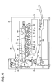
- FIG. 1 illustrates a cross section of a schematic configuration of an image forming apparatus 1.
- the image forming apparatus 1 is, for example, a color printer of a tandem engine. As illustrated in FIG. 1 , the image forming apparatus 1 includes an intermediate transfer belt 7, a primary transfer unit 8, a secondary transfer unit 9, a fixing unit 11, a light scanning device 15, and a plurality of image forming units 16.
- the image forming apparatus 1 includes a sheet feed cassette 3 at a lower portion inside of a main body 2.
- the sheet feed cassette 3 internally loads and houses paper sheets (not illustrated) such as a cut paper before printing.
- a first paper sheet conveyor 21 is located at a side of the sheet feed cassette 3. The first paper sheet conveyor 21 receives the paper sheet sent out from the sheet feed cassette 3, and then conveys the paper sheet to the secondary transfer unit 9, which is located upward.
- a manual paper feed tray 5 is located at a right side of the sheet feed cassette 3. At the left side of the manual paper feed tray 5, a second paper sheet conveyor 22 is located. The second paper sheet conveyor 22 receives the paper sheet or a similar sheet sent out from the manual paper feed tray 5 and conveys the paper sheet or a similar sheet to the first paper sheet conveyor 21.
- the light scanning device 15 is arranged above the second paper sheet conveyor 22.
- the light scanning device 15 irradiates laser beam on the image forming units 16 based on image data received by the image forming apparatus 1.
- the image forming units 16 are located at an upper side of the light scanning device 15.
- the endless intermediate transfer belt 7 is located at the upper side of the respective image forming units 16.
- the intermediate transfer belt 7 is wound and hung around a plurality of rollers and is rotatably driven by a driving device (not illustrated).
- the four image forming units 16 are arranged in a row along the intermediate transfer belt 7 as illustrated in FIG. 1 .
- the four image forming units 16 form respective toner images of yellow (Y), magenta (M), cyan (C), or black (BK).
- the image forming unit 16 includes a photoreceptor drum 31, which is a photoreceptor, a charger 32, a developing apparatus 33, and a cleaning apparatus 10, which are each arranged at a peripheral area of the photoreceptor drum 31.
- the photoreceptor drum 31 is rotatably driven by a driving mortar (not illustrated).
- the charger 32 uniformly charges an outer peripheral surface of the photoreceptor drum 31 at a predetermined electric potential with a charging bias applied from a charging bias power source (not illustrated). Then, writing light emitted from the light scanning device 15 forms an electrostatic latent image on the respective photoreceptor drums 31.
- the developing apparatus 33 houses respective toner with magenta, toner with cyan, toner with yellow, and toner with black.
- the developing apparatus 33 causes toner to adhere to the electrostatic latent image of the photoreceptor drum 31 depending on the respective colors develops the electrostatic latent image.
- the electrostatic latent images on the respective photoreceptor drums 31 are visualized as toner images.
- the primary transfer units 8 are arranged at the upper side of the respective image forming units 16.
- the primary transfer units 8 include transfer rollers.
- the primary transfer rollers primarily transfer the toner images formed by the image forming units 16 to the surface of the intermediate transfer belt 7.
- the cleaning apparatus 10 of the image forming unit 16 cleans the outer peripheral surface of the photoreceptor drum 31 to remove the remaining toner and the foreign object.
- the intermediate transfer belt 7 is rotatably driven, and the toner images of the respective image forming units 16 are transferred to the intermediate transfer belt 7 at a predetermined timing. Then, a color toner image formed by mutually superimposing the toner images with four colors, yellow, magenta, cyan, and black, is formed at the surface of the intermediate transfer belt 7.
- the secondary transfer unit 9 includes a transfer roller 18 arranged at the left side of the intermediate transfer belt 7.
- the secondary transfer unit 9 causes the transfer roller 18 to transfer the toner image on the intermediate transfer belt 7 to a paper sheet.
- the fixing unit 11 is located at the upper side of the secondary transfer unit 9.
- a third paper sheet conveyor 23 is formed between the secondary transfer unit 9 and the fixing unit 11. The third paper sheet conveyor 23 conveys the paper sheet on which the toner image has been secondarily transferred to the fixing unit 11.
- the fixing unit 11 includes a fixing roller 19 and a pressure roller 20 that each rotate.
- the fixing unit 11 heats and pressurizes the paper sheet with the fixing roller 19 and the pressure roller 20 to fix the toner image on the paper sheet.
- the light scanning device 15 light-scans the photoreceptor drum 31 based on the image data to form the electrostatic latent image on the photoreceptor drum 31.
- the developing apparatus 33 develops the electrostatic latent image of the photoreceptor drum 31 as toner images with respective colors.
- the primary transfer unit 8 transfers the toner images with the respective colors from the photoreceptor drum 31 to the intermediate transfer belt 7.
- the secondary transfer unit 9 transfers the toner images on the intermediate transfer belt 7 to the paper sheet conveyed from the first paper sheet conveyor 21. Afterwards, the paper sheet on which the toner images have been fixed by the fixing unit 11 is discharged to a paper sheet discharge unit 28.
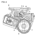
- FIG. 2 illustrates structures of the cleaning apparatus 10, the charger 32, and the photoreceptor drum 31.
- FIG. 3 illustrates the enlarged cleaning apparatus 10.
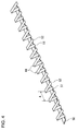
- FIG. 4 illustrates an external appearance of a toner crushing member 44.
- FIG. 5 illustrates an enlarged toner crushing member 44 and a screw 43.
- the cleaning apparatus 10 as illustrated in FIG. 2 , includes a brush 41, a blade 42, the screw 43, the toner crushing member 44, and a casing 45.
- the casing 45 for example, houses the brush 41, the screw 43, and the toner crushing member 44.
- the casing 45 rotatably supports both ends of the brush 41.
- the brush 41 rotates around an axis parallel to the photoreceptor drum 31 while being in contact with the outer peripheral surface of the photoreceptor drum 31.
- the photoreceptor drum 31 rotates anticlockwise.
- the brush 41 rotates clockwise, which is the reverse direction of the photoreceptor drum 31.
- the blade 42 is arranged such that a side end portion of the blade 42 abuts on the outer peripheral surface of the photoreceptor drum 31 in contact with the brush 41. Then, by slidably in contact with the outer peripheral surface of the rotating photoreceptor drum 31, the blade 42 causes the toner remaining on the outer peripheral surface of the photoreceptor drum 31 to separate from the photoreceptor drum 31.
- the screw 43 as illustrated in FIG. 5 , includes a shaft unit 48 and a spirally-patterned fin 49.
- the shaft unit 48 rotatably supports the casing 45.
- the fin 49 is integrally formed with the shaft unit 48 so as to be wound around the shaft unit 48.
- the screw 43 rotates around an axis parallel to a rotation shaft of the photoreceptor drum 31.
- the screw 43 rotates in the reverse direction of the rotation direction of the photoreceptor drum 31, which is the clockwise direction in FIG. 2 .
- the screw 43 conveys the toner separated from the photoreceptor drum 31 with the blade 42 in the axial direction of the shaft unit 48.
- the toner crushing member 44 is located in contact with the screw 43. The rotation of the screw 43 swings the toner crushing member 44, thus crushing the toner accumulated between the screw 43 and the blade 42.
- the toner crushing member 44 is, for example, constituted of an elastic strip-shaped sheet material made of, for example, PET.
- the fin 49 of the screw 43 is in contact from a base end side, which is a fixed end side of a first part 51, to a distal end side, which is a free end side. This ensures preventing entanglement of the toner crushing member 44 to the screw 43. Additionally, a second part 52 can preferably crush the toner accumulated between the blade 42 and the screw 43.
- the toner accumulated between the blade 42 and the screw 43 can be efficiently conveyed to the screw 43, while the toner crushing member 44 can appropriately crush the toner between the blade 42 and the screw 43.
- the toner crushing member 44 as illustrated in FIG. 2 to FIG. 5 , includes the first part 51 and the second part 52.
- the base end side of the first part 51 is secured to the casing 45.
- the second part 52 is folded back at the distal end side of the first part 51.
- the second part 52 is longer than the first part 51. This ensures efficiently crushing the toner accumulated at a region distant farther from the screw 43 than the base end side of the first part 51, also further ensuring that the second part 52 is less likely to be wrapped up by the screw 43.
- a plate-shaped supporting member 50 supports the respective toner crushing members 44 at the base end side of the first part 51.
- a bracket portion 59 is mounted and secured to the casing 45.
- the bracket portion 59 extends along the screw 43.
- a side surface of the bracket portion 59 opposed to the screw 43 is formed into a concave curved surface.
- a base end portion of a plate-shaped toner scraper 53 is mounted to a side surface opposite side from the screw 43 of the bracket portion 59.
- the distal end portion of the toner scraper 53 is in contact with the brush 41.
- the toner scraper 53 scrapes off the toner adhered to the brush 41 to between the blade 42 and the screw 43 with its distal end portion.
- the toner scraper 53 has a plurality of openings (not illustrated). This causes the toner to pass through the screw 43 side from the blade 42 side via the openings.
- the bracket portion 59 and the toner scraper 53 sandwich the supporting member 50 to which the toner crushing member 44 is mounted. Accordingly, the first part 51 of the toner crushing member 44 is secured to the casing 45 while the distal end side of the first part 51 and the second part 52 are freely swingable.
- the toner crushing member 44 is constituted such that the distal end side of the second part 52 swings between the blade 42 and the screw 43 in association with the rotation of the screw 43. Accordingly, the distal end side of the second part 52 crushes the toner accumulated between the blade 42 and the screw 43.
- the pitch A of the toner crushing members 44 differs from a pitch B of the fins 49 at the screw 43, thus the pitch A is larger than the pitch B.
- the blade 42 is slidably in contact with the outer peripheral surface of the photoreceptor drum 31 swept by the brush 41. Accordingly, the blade 42 separates the toner remaining on the outer peripheral surface of the photoreceptor drum 31 from the photoreceptor drum 31, thus the toner accumulates between the blade 42 and the screw 43. If the amount of accumulated toner increases, the toner passes through the openings of the toner scraper 53 from the blades 42 side and is extruded to the screw 43 side. The toner crushing member 44 stirs and crushes the toner extruded to between the toner scraper 53 and the screw 43.
- the fin 49 of the screw 43 is in contact with the toner crushing member 44.
- the rotation of the screw 43 causes the fin 49 to contact the first part 51 from the base end side to the distal end side of the first part 51.
- the distal end side of the second part 52 swings between the toner scraper 53 and the screw 43.
- the swinging second part 52 crushes a lump of the toner extruded to between the toner scraper 53 and the screw 43.
- the toner extruded from the blade 42 side to the screw 43 side is crushed by the toner crushing member 44, moves to the screw 43, and then is conveyed by the screw 43.
- This embodiment rotates the screw 43 to the reverse direction of the rotation direction of the photoreceptor drum 31. Accordingly, the screw 43 can take in the toner extruded from the blade 42 to the screw 43 along the extruded direction. This ensures efficiently conveying the toner separated from the photoreceptor drum 31 to the screw 43.
- the image forming apparatus may be another image forming apparatus that includes the light scanning device 15 such as a copier, a scanner device, or a multi-functional peripheral.
- the disclosure is applicable to the cleaning apparatus, the image forming apparatus, and the toner crushing member.
Landscapes
- Physics & Mathematics (AREA)
- General Physics & Mathematics (AREA)
- Life Sciences & Earth Sciences (AREA)
- Engineering & Computer Science (AREA)
- Environmental & Geological Engineering (AREA)
- Sustainable Development (AREA)
- Cleaning In Electrography (AREA)
Applications Claiming Priority (1)
| Application Number | Priority Date | Filing Date | Title |
|---|---|---|---|
| JP2013187475A JP5947764B2 (ja) | 2013-09-10 | 2013-09-10 | クリーニング装置、画像形成装置及びトナー崩し部材 |
Publications (2)
| Publication Number | Publication Date |
|---|---|
| EP2846200A1 true EP2846200A1 (de) | 2015-03-11 |
| EP2846200B1 EP2846200B1 (de) | 2018-10-31 |
Family
ID=51454615
Family Applications (1)
| Application Number | Title | Priority Date | Filing Date |
|---|---|---|---|
| EP14183516.5A Active EP2846200B1 (de) | 2013-09-10 | 2014-09-04 | Reinigungsvorrichtung mit einem tonerbrechelement und bilderzeugungsvorrichtung |
Country Status (4)
| Country | Link |
|---|---|
| US (1) | US9176455B2 (de) |
| EP (1) | EP2846200B1 (de) |
| JP (1) | JP5947764B2 (de) |
| CN (1) | CN104423235B (de) |
Families Citing this family (13)
| Publication number | Priority date | Publication date | Assignee | Title |
|---|---|---|---|---|
| JP5906221B2 (ja) * | 2013-08-16 | 2016-04-20 | 株式会社沖データ | 現像剤搬送装置及び画像形成装置 |
| JP6170468B2 (ja) * | 2014-05-27 | 2017-07-26 | 京セラドキュメントソリューションズ株式会社 | クリーニング装置及び画像形成装置 |
| KR101689868B1 (ko) * | 2014-06-10 | 2017-01-09 | 에스프린팅솔루션 주식회사 | 토너 카트리지 및 이를 채용한 전자사진방식 화상형성장치 |
| JP6354681B2 (ja) * | 2015-06-30 | 2018-07-11 | 京セラドキュメントソリューションズ株式会社 | 画像形成装置、シートガイド |
| JP6432555B2 (ja) * | 2016-04-06 | 2018-12-05 | 京セラドキュメントソリューションズ株式会社 | クリーニング装置およびそれを備えた画像形成装置 |
| JP6497352B2 (ja) | 2016-04-27 | 2019-04-10 | 京セラドキュメントソリューションズ株式会社 | トナー搬送装置、画像形成装置 |
| JP6500856B2 (ja) * | 2016-07-28 | 2019-04-17 | 京セラドキュメントソリューションズ株式会社 | クリーニング装置及び画像形成装置 |
| CN106873330B (zh) * | 2017-04-27 | 2023-12-05 | 珠海华人智创科技有限公司 | 一种调色剂供给补充容器 |
| JP6911528B2 (ja) * | 2017-05-25 | 2021-07-28 | 株式会社リコー | トナー搬送装置及び画像形成装置 |
| US10866537B2 (en) * | 2018-03-13 | 2020-12-15 | Ricoh Company, Ltd. | Powder container having contact portion to contact a restriction member |
| US11209766B2 (en) * | 2019-10-31 | 2021-12-28 | Canon Kabushiki Kaisha | Cleaning device and image forming apparatus |
| CN112847937B (zh) * | 2021-02-25 | 2022-10-21 | 汕头市谷源新能源有限公司 | 一种废旧热固性塑料再生设备及再生工艺 |
| JP2024168196A (ja) * | 2023-05-23 | 2024-12-05 | 株式会社リコー | 粉体回収容器、画像形成装置および粉体搬送装置 |
Citations (2)
| Publication number | Priority date | Publication date | Assignee | Title |
|---|---|---|---|---|
| JP2008158168A (ja) * | 2006-12-22 | 2008-07-10 | Kyocera Mita Corp | クリーニング装置及びそれを備えた画像形成装置 |
| EP2587318A1 (de) * | 2011-10-27 | 2013-05-01 | Kyocera Document Solutions Inc. | Tonerfördervorrichtung und Bilderzeugungsvorrichtung mit der Tonerfördervorrichtung |
Family Cites Families (10)
| Publication number | Priority date | Publication date | Assignee | Title |
|---|---|---|---|---|
| JPH01262577A (ja) * | 1988-04-14 | 1989-10-19 | Sharp Corp | 画像形成装置のクリーニング装置 |
| JP2675445B2 (ja) * | 1991-03-15 | 1997-11-12 | シャープ株式会社 | 電子写真装置のクリーニング装置 |
| JP2005037511A (ja) * | 2003-07-17 | 2005-02-10 | Konica Minolta Business Technologies Inc | 現像剤搬送装置及び該現像剤搬送装置を備えた画像形成装置 |
| JP4311627B2 (ja) | 2003-08-29 | 2009-08-12 | 京セラミタ株式会社 | クリーニング装置およびこの装置が適用された画像形成装置 |
| JP2006259426A (ja) * | 2005-03-18 | 2006-09-28 | Ricoh Co Ltd | 粉体搬送装置及び画像形成装置 |
| JP4890338B2 (ja) * | 2007-04-25 | 2012-03-07 | 株式会社リコー | トナー収容器及び画像形成装置 |
| JP5073463B2 (ja) * | 2007-11-30 | 2012-11-14 | 株式会社リコー | クリーニング装置、像担持体ユニット及び画像形成装置 |
| JP5234426B2 (ja) * | 2008-12-05 | 2013-07-10 | 株式会社リコー | トナー搬送装置及び画像形成装置 |
| JP5155982B2 (ja) * | 2009-10-28 | 2013-03-06 | 京セラドキュメントソリューションズ株式会社 | クリーニング装置及びこれを備えた画像形成装置 |
| JP5492860B2 (ja) * | 2011-10-27 | 2014-05-14 | 京セラドキュメントソリューションズ株式会社 | トナー搬送装置及びこれを備える画像形成装置 |
-
2013
- 2013-09-10 JP JP2013187475A patent/JP5947764B2/ja active Active
-
2014
- 2014-08-28 CN CN201410432893.7A patent/CN104423235B/zh active Active
- 2014-09-04 EP EP14183516.5A patent/EP2846200B1/de active Active
- 2014-09-10 US US14/481,923 patent/US9176455B2/en active Active
Patent Citations (2)
| Publication number | Priority date | Publication date | Assignee | Title |
|---|---|---|---|---|
| JP2008158168A (ja) * | 2006-12-22 | 2008-07-10 | Kyocera Mita Corp | クリーニング装置及びそれを備えた画像形成装置 |
| EP2587318A1 (de) * | 2011-10-27 | 2013-05-01 | Kyocera Document Solutions Inc. | Tonerfördervorrichtung und Bilderzeugungsvorrichtung mit der Tonerfördervorrichtung |
Also Published As
| Publication number | Publication date |
|---|---|
| CN104423235A (zh) | 2015-03-18 |
| US9176455B2 (en) | 2015-11-03 |
| EP2846200B1 (de) | 2018-10-31 |
| JP2015055675A (ja) | 2015-03-23 |
| CN104423235B (zh) | 2017-04-12 |
| US20150071691A1 (en) | 2015-03-12 |
| JP5947764B2 (ja) | 2016-07-06 |
Similar Documents
| Publication | Publication Date | Title |
|---|---|---|
| US9176455B2 (en) | Cleaning apparatus, image forming apparatus, and toner crushing member | |
| CN103852992B (zh) | 清洁装置、中间转印单元和图像形成装置 | |
| JP3870204B2 (ja) | 画像形成装置 | |
| US10018941B2 (en) | Cleaning device, and image forming apparatus and process unit incorporating same | |
| US7725070B2 (en) | Waste toner collecting device and image forming apparatus loaded therewith | |
| JP5515886B2 (ja) | 現像剤回収装置及びこれを用いた画像形成装置 | |
| JP6477580B2 (ja) | トナー搬送装置およびそれを備えた画像形成装置 | |
| JP5927167B2 (ja) | 画像形成装置 | |
| JP2006078853A (ja) | クリーニング装置及び画像形成装置 | |
| JP6821927B2 (ja) | 清掃装置及び画像形成装置 | |
| JP5949087B2 (ja) | 粉体搬送装置、プロセスカートリッジ、及び画像形成装置 | |
| US7848675B2 (en) | Image forming apparatus | |
| JP5945528B2 (ja) | トナー搬送装置及び画像形成装置 | |
| JP6233291B2 (ja) | 画像形成装置 | |
| JP6062053B2 (ja) | 画像形成装置 | |
| JP2007241192A (ja) | 画像形成装置 | |
| JP2017037262A (ja) | 画像形成装置 | |
| JP2011180309A (ja) | 画像形成装置 | |
| JP6635065B2 (ja) | クリーニング装置及び画像形成装置 | |
| US9411265B2 (en) | Developer conveying mechanism, image forming apparatus | |
| JP5085917B2 (ja) | 回転体のアース接地構造、ベルト装置及び画像形成装置 | |
| JP6645242B2 (ja) | 画像形成装置 | |
| JP5278063B2 (ja) | 現像剤搬送装置及び画像形成装置 | |
| JP2010190999A (ja) | 現像剤回収装置及び画像形成装置 | |
| JP2014035481A (ja) | ベルト搬送ユニット、及び画像形成装置 |
Legal Events
| Date | Code | Title | Description |
|---|---|---|---|
| 17P | Request for examination filed |
Effective date: 20140904 |
|
| AK | Designated contracting states |
Kind code of ref document: A1 Designated state(s): AL AT BE BG CH CY CZ DE DK EE ES FI FR GB GR HR HU IE IS IT LI LT LU LV MC MK MT NL NO PL PT RO RS SE SI SK SM TR |
|
| AX | Request for extension of the european patent |
Extension state: BA ME |
|
| PUAI | Public reference made under article 153(3) epc to a published international application that has entered the european phase |
Free format text: ORIGINAL CODE: 0009012 |
|
| R17P | Request for examination filed (corrected) |
Effective date: 20150610 |
|
| RBV | Designated contracting states (corrected) |
Designated state(s): AL AT BE BG CH CY CZ DE DK EE ES FI FR GB GR HR HU IE IS IT LI LT LU LV MC MK MT NL NO PL PT RO RS SE SI SK SM TR |
|
| STAA | Information on the status of an ep patent application or granted ep patent |
Free format text: STATUS: EXAMINATION IS IN PROGRESS |
|
| 17Q | First examination report despatched |
Effective date: 20171214 |
|
| GRAP | Despatch of communication of intention to grant a patent |
Free format text: ORIGINAL CODE: EPIDOSNIGR1 |
|
| STAA | Information on the status of an ep patent application or granted ep patent |
Free format text: STATUS: GRANT OF PATENT IS INTENDED |
|
| INTG | Intention to grant announced |
Effective date: 20180620 |
|
| RIN1 | Information on inventor provided before grant (corrected) |
Inventor name: FUJII, HIROKAZU |
|
| GRAS | Grant fee paid |
Free format text: ORIGINAL CODE: EPIDOSNIGR3 |
|
| GRAA | (expected) grant |
Free format text: ORIGINAL CODE: 0009210 |
|
| STAA | Information on the status of an ep patent application or granted ep patent |
Free format text: STATUS: THE PATENT HAS BEEN GRANTED |
|
| AK | Designated contracting states |
Kind code of ref document: B1 Designated state(s): AL AT BE BG CH CY CZ DE DK EE ES FI FR GB GR HR HU IE IS IT LI LT LU LV MC MK MT NL NO PL PT RO RS SE SI SK SM TR |
|
| REG | Reference to a national code |
Ref country code: CH Ref legal event code: EP Ref country code: GB Ref legal event code: FG4D |
|
| REG | Reference to a national code |
Ref country code: AT Ref legal event code: REF Ref document number: 1060127 Country of ref document: AT Kind code of ref document: T Effective date: 20181115 |
|
| REG | Reference to a national code |
Ref country code: DE Ref legal event code: R096 Ref document number: 602014034995 Country of ref document: DE |
|
| REG | Reference to a national code |
Ref country code: IE Ref legal event code: FG4D |
|
| REG | Reference to a national code |
Ref country code: NL Ref legal event code: MP Effective date: 20181031 |
|
| REG | Reference to a national code |
Ref country code: LT Ref legal event code: MG4D |
|
| REG | Reference to a national code |
Ref country code: AT Ref legal event code: MK05 Ref document number: 1060127 Country of ref document: AT Kind code of ref document: T Effective date: 20181031 |
|
| PG25 | Lapsed in a contracting state [announced via postgrant information from national office to epo] |
Ref country code: FI Free format text: LAPSE BECAUSE OF FAILURE TO SUBMIT A TRANSLATION OF THE DESCRIPTION OR TO PAY THE FEE WITHIN THE PRESCRIBED TIME-LIMIT Effective date: 20181031 Ref country code: NO Free format text: LAPSE BECAUSE OF FAILURE TO SUBMIT A TRANSLATION OF THE DESCRIPTION OR TO PAY THE FEE WITHIN THE PRESCRIBED TIME-LIMIT Effective date: 20190131 Ref country code: LT Free format text: LAPSE BECAUSE OF FAILURE TO SUBMIT A TRANSLATION OF THE DESCRIPTION OR TO PAY THE FEE WITHIN THE PRESCRIBED TIME-LIMIT Effective date: 20181031 Ref country code: HR Free format text: LAPSE BECAUSE OF FAILURE TO SUBMIT A TRANSLATION OF THE DESCRIPTION OR TO PAY THE FEE WITHIN THE PRESCRIBED TIME-LIMIT Effective date: 20181031 Ref country code: BG Free format text: LAPSE BECAUSE OF FAILURE TO SUBMIT A TRANSLATION OF THE DESCRIPTION OR TO PAY THE FEE WITHIN THE PRESCRIBED TIME-LIMIT Effective date: 20190131 Ref country code: PL Free format text: LAPSE BECAUSE OF FAILURE TO SUBMIT A TRANSLATION OF THE DESCRIPTION OR TO PAY THE FEE WITHIN THE PRESCRIBED TIME-LIMIT Effective date: 20181031 Ref country code: ES Free format text: LAPSE BECAUSE OF FAILURE TO SUBMIT A TRANSLATION OF THE DESCRIPTION OR TO PAY THE FEE WITHIN THE PRESCRIBED TIME-LIMIT Effective date: 20181031 Ref country code: LV Free format text: LAPSE BECAUSE OF FAILURE TO SUBMIT A TRANSLATION OF THE DESCRIPTION OR TO PAY THE FEE WITHIN THE PRESCRIBED TIME-LIMIT Effective date: 20181031 Ref country code: AT Free format text: LAPSE BECAUSE OF FAILURE TO SUBMIT A TRANSLATION OF THE DESCRIPTION OR TO PAY THE FEE WITHIN THE PRESCRIBED TIME-LIMIT Effective date: 20181031 Ref country code: IS Free format text: LAPSE BECAUSE OF FAILURE TO SUBMIT A TRANSLATION OF THE DESCRIPTION OR TO PAY THE FEE WITHIN THE PRESCRIBED TIME-LIMIT Effective date: 20190228 |
|
| PG25 | Lapsed in a contracting state [announced via postgrant information from national office to epo] |
Ref country code: AL Free format text: LAPSE BECAUSE OF FAILURE TO SUBMIT A TRANSLATION OF THE DESCRIPTION OR TO PAY THE FEE WITHIN THE PRESCRIBED TIME-LIMIT Effective date: 20181031 Ref country code: PT Free format text: LAPSE BECAUSE OF FAILURE TO SUBMIT A TRANSLATION OF THE DESCRIPTION OR TO PAY THE FEE WITHIN THE PRESCRIBED TIME-LIMIT Effective date: 20190301 Ref country code: NL Free format text: LAPSE BECAUSE OF FAILURE TO SUBMIT A TRANSLATION OF THE DESCRIPTION OR TO PAY THE FEE WITHIN THE PRESCRIBED TIME-LIMIT Effective date: 20181031 Ref country code: GR Free format text: LAPSE BECAUSE OF FAILURE TO SUBMIT A TRANSLATION OF THE DESCRIPTION OR TO PAY THE FEE WITHIN THE PRESCRIBED TIME-LIMIT Effective date: 20190201 Ref country code: RS Free format text: LAPSE BECAUSE OF FAILURE TO SUBMIT A TRANSLATION OF THE DESCRIPTION OR TO PAY THE FEE WITHIN THE PRESCRIBED TIME-LIMIT Effective date: 20181031 Ref country code: SE Free format text: LAPSE BECAUSE OF FAILURE TO SUBMIT A TRANSLATION OF THE DESCRIPTION OR TO PAY THE FEE WITHIN THE PRESCRIBED TIME-LIMIT Effective date: 20181031 |
|
| PG25 | Lapsed in a contracting state [announced via postgrant information from national office to epo] |
Ref country code: DK Free format text: LAPSE BECAUSE OF FAILURE TO SUBMIT A TRANSLATION OF THE DESCRIPTION OR TO PAY THE FEE WITHIN THE PRESCRIBED TIME-LIMIT Effective date: 20181031 Ref country code: IT Free format text: LAPSE BECAUSE OF FAILURE TO SUBMIT A TRANSLATION OF THE DESCRIPTION OR TO PAY THE FEE WITHIN THE PRESCRIBED TIME-LIMIT Effective date: 20181031 Ref country code: CZ Free format text: LAPSE BECAUSE OF FAILURE TO SUBMIT A TRANSLATION OF THE DESCRIPTION OR TO PAY THE FEE WITHIN THE PRESCRIBED TIME-LIMIT Effective date: 20181031 |
|
| REG | Reference to a national code |
Ref country code: DE Ref legal event code: R097 Ref document number: 602014034995 Country of ref document: DE |
|
| PG25 | Lapsed in a contracting state [announced via postgrant information from national office to epo] |
Ref country code: SK Free format text: LAPSE BECAUSE OF FAILURE TO SUBMIT A TRANSLATION OF THE DESCRIPTION OR TO PAY THE FEE WITHIN THE PRESCRIBED TIME-LIMIT Effective date: 20181031 Ref country code: RO Free format text: LAPSE BECAUSE OF FAILURE TO SUBMIT A TRANSLATION OF THE DESCRIPTION OR TO PAY THE FEE WITHIN THE PRESCRIBED TIME-LIMIT Effective date: 20181031 Ref country code: SM Free format text: LAPSE BECAUSE OF FAILURE TO SUBMIT A TRANSLATION OF THE DESCRIPTION OR TO PAY THE FEE WITHIN THE PRESCRIBED TIME-LIMIT Effective date: 20181031 Ref country code: EE Free format text: LAPSE BECAUSE OF FAILURE TO SUBMIT A TRANSLATION OF THE DESCRIPTION OR TO PAY THE FEE WITHIN THE PRESCRIBED TIME-LIMIT Effective date: 20181031 |
|
| PLBE | No opposition filed within time limit |
Free format text: ORIGINAL CODE: 0009261 |
|
| STAA | Information on the status of an ep patent application or granted ep patent |
Free format text: STATUS: NO OPPOSITION FILED WITHIN TIME LIMIT |
|
| 26N | No opposition filed |
Effective date: 20190801 |
|
| PG25 | Lapsed in a contracting state [announced via postgrant information from national office to epo] |
Ref country code: SI Free format text: LAPSE BECAUSE OF FAILURE TO SUBMIT A TRANSLATION OF THE DESCRIPTION OR TO PAY THE FEE WITHIN THE PRESCRIBED TIME-LIMIT Effective date: 20181031 |
|
| PG25 | Lapsed in a contracting state [announced via postgrant information from national office to epo] |
Ref country code: TR Free format text: LAPSE BECAUSE OF FAILURE TO SUBMIT A TRANSLATION OF THE DESCRIPTION OR TO PAY THE FEE WITHIN THE PRESCRIBED TIME-LIMIT Effective date: 20181031 |
|
| PG25 | Lapsed in a contracting state [announced via postgrant information from national office to epo] |
Ref country code: MC Free format text: LAPSE BECAUSE OF FAILURE TO SUBMIT A TRANSLATION OF THE DESCRIPTION OR TO PAY THE FEE WITHIN THE PRESCRIBED TIME-LIMIT Effective date: 20181031 |
|
| REG | Reference to a national code |
Ref country code: CH Ref legal event code: PL |
|
| PG25 | Lapsed in a contracting state [announced via postgrant information from national office to epo] |
Ref country code: LU Free format text: LAPSE BECAUSE OF NON-PAYMENT OF DUE FEES Effective date: 20190904 Ref country code: IE Free format text: LAPSE BECAUSE OF NON-PAYMENT OF DUE FEES Effective date: 20190904 Ref country code: CH Free format text: LAPSE BECAUSE OF NON-PAYMENT OF DUE FEES Effective date: 20190930 Ref country code: LI Free format text: LAPSE BECAUSE OF NON-PAYMENT OF DUE FEES Effective date: 20190930 |
|
| REG | Reference to a national code |
Ref country code: BE Ref legal event code: MM Effective date: 20190930 |
|
| PG25 | Lapsed in a contracting state [announced via postgrant information from national office to epo] |
Ref country code: BE Free format text: LAPSE BECAUSE OF NON-PAYMENT OF DUE FEES Effective date: 20190930 |
|
| PG25 | Lapsed in a contracting state [announced via postgrant information from national office to epo] |
Ref country code: CY Free format text: LAPSE BECAUSE OF FAILURE TO SUBMIT A TRANSLATION OF THE DESCRIPTION OR TO PAY THE FEE WITHIN THE PRESCRIBED TIME-LIMIT Effective date: 20181031 |
|
| PG25 | Lapsed in a contracting state [announced via postgrant information from national office to epo] |
Ref country code: MT Free format text: LAPSE BECAUSE OF FAILURE TO SUBMIT A TRANSLATION OF THE DESCRIPTION OR TO PAY THE FEE WITHIN THE PRESCRIBED TIME-LIMIT Effective date: 20181031 Ref country code: HU Free format text: LAPSE BECAUSE OF FAILURE TO SUBMIT A TRANSLATION OF THE DESCRIPTION OR TO PAY THE FEE WITHIN THE PRESCRIBED TIME-LIMIT; INVALID AB INITIO Effective date: 20140904 |
|
| PG25 | Lapsed in a contracting state [announced via postgrant information from national office to epo] |
Ref country code: MK Free format text: LAPSE BECAUSE OF FAILURE TO SUBMIT A TRANSLATION OF THE DESCRIPTION OR TO PAY THE FEE WITHIN THE PRESCRIBED TIME-LIMIT Effective date: 20181031 |
|
| P01 | Opt-out of the competence of the unified patent court (upc) registered |
Effective date: 20230420 |
|
| PGFP | Annual fee paid to national office [announced via postgrant information from national office to epo] |
Ref country code: DE Payment date: 20250820 Year of fee payment: 12 |
|
| PGFP | Annual fee paid to national office [announced via postgrant information from national office to epo] |
Ref country code: GB Payment date: 20250827 Year of fee payment: 12 |
|
| PGFP | Annual fee paid to national office [announced via postgrant information from national office to epo] |
Ref country code: FR Payment date: 20250820 Year of fee payment: 12 |