EP2587497A2 - Appareil de protection et appareil de transmission de puissance sans fil - Google Patents
Appareil de protection et appareil de transmission de puissance sans fil Download PDFInfo
- Publication number
- EP2587497A2 EP2587497A2 EP12188604.8A EP12188604A EP2587497A2 EP 2587497 A2 EP2587497 A2 EP 2587497A2 EP 12188604 A EP12188604 A EP 12188604A EP 2587497 A2 EP2587497 A2 EP 2587497A2
- Authority
- EP
- European Patent Office
- Prior art keywords
- shielding
- shielding unit
- magnetic field
- permeability
- wireless power
- Prior art date
- Legal status (The legal status is an assumption and is not a legal conclusion. Google has not performed a legal analysis and makes no representation as to the accuracy of the status listed.)
- Granted
Links
Images


Classifications
-
- H—ELECTRICITY
- H01—ELECTRIC ELEMENTS
- H01F—MAGNETS; INDUCTANCES; TRANSFORMERS; SELECTION OF MATERIALS FOR THEIR MAGNETIC PROPERTIES
- H01F38/00—Adaptations of transformers or inductances for specific applications or functions
- H01F38/14—Inductive couplings
-
- H—ELECTRICITY
- H01—ELECTRIC ELEMENTS
- H01F—MAGNETS; INDUCTANCES; TRANSFORMERS; SELECTION OF MATERIALS FOR THEIR MAGNETIC PROPERTIES
- H01F27/00—Details of transformers or inductances, in general
- H01F27/34—Special means for preventing or reducing unwanted electric or magnetic effects, e.g. no-load losses, reactive currents, harmonics, oscillations, leakage fields
- H01F27/36—Electric or magnetic shields or screens
- H01F27/361—Electric or magnetic shields or screens made of combinations of electrically conductive material and ferromagnetic material
-
- H—ELECTRICITY
- H01—ELECTRIC ELEMENTS
- H01F—MAGNETS; INDUCTANCES; TRANSFORMERS; SELECTION OF MATERIALS FOR THEIR MAGNETIC PROPERTIES
- H01F27/00—Details of transformers or inductances, in general
- H01F27/34—Special means for preventing or reducing unwanted electric or magnetic effects, e.g. no-load losses, reactive currents, harmonics, oscillations, leakage fields
- H01F27/36—Electric or magnetic shields or screens
- H01F27/366—Electric or magnetic shields or screens made of ferromagnetic material
-
- H—ELECTRICITY
- H02—GENERATION; CONVERSION OR DISTRIBUTION OF ELECTRIC POWER
- H02J—ELECTRIC POWER NETWORKS; CIRCUIT ARRANGEMENTS OR SYSTEMS FOR SUPPLYING OR DISTRIBUTING ELECTRIC POWER; SYSTEMS FOR STORING ELECTRIC ENERGY
- H02J50/00—Circuit arrangements or systems for wireless supply or distribution of electric power
- H02J50/005—Mechanical details of housing or structure aiming to accommodate the power transfer means, e.g. mechanical integration of coils, antennas or transducers into emitting or receiving devices
-
- H—ELECTRICITY
- H02—GENERATION; CONVERSION OR DISTRIBUTION OF ELECTRIC POWER
- H02J—ELECTRIC POWER NETWORKS; CIRCUIT ARRANGEMENTS OR SYSTEMS FOR SUPPLYING OR DISTRIBUTING ELECTRIC POWER; SYSTEMS FOR STORING ELECTRIC ENERGY
- H02J50/00—Circuit arrangements or systems for wireless supply or distribution of electric power
- H02J50/10—Circuit arrangements or systems for wireless supply or distribution of electric power using inductive coupling
- H02J50/12—Circuit arrangements or systems for wireless supply or distribution of electric power using inductive coupling of the resonant type
-
- H—ELECTRICITY
- H02—GENERATION; CONVERSION OR DISTRIBUTION OF ELECTRIC POWER
- H02J—ELECTRIC POWER NETWORKS; CIRCUIT ARRANGEMENTS OR SYSTEMS FOR SUPPLYING OR DISTRIBUTING ELECTRIC POWER; SYSTEMS FOR STORING ELECTRIC ENERGY
- H02J50/00—Circuit arrangements or systems for wireless supply or distribution of electric power
- H02J50/70—Circuit arrangements or systems for wireless supply or distribution of electric power involving the reduction of electric, magnetic or electromagnetic leakage fields
-
- H—ELECTRICITY
- H02—GENERATION; CONVERSION OR DISTRIBUTION OF ELECTRIC POWER
- H02J—ELECTRIC POWER NETWORKS; CIRCUIT ARRANGEMENTS OR SYSTEMS FOR SUPPLYING OR DISTRIBUTING ELECTRIC POWER; SYSTEMS FOR STORING ELECTRIC ENERGY
- H02J50/00—Circuit arrangements or systems for wireless supply or distribution of electric power
- H02J50/80—Circuit arrangements or systems for wireless supply or distribution of electric power involving the exchange of data, concerning supply or distribution of electric power, between transmitting devices and receiving devices
-
- H—ELECTRICITY
- H04—ELECTRIC COMMUNICATION TECHNIQUE
- H04B—TRANSMISSION
- H04B5/00—Near-field transmission systems, e.g. inductive or capacitive transmission systems
- H04B5/20—Near-field transmission systems, e.g. inductive or capacitive transmission systems characterised by the transmission technique; characterised by the transmission medium
- H04B5/24—Inductive coupling
- H04B5/26—Inductive coupling using coils
-
- H—ELECTRICITY
- H04—ELECTRIC COMMUNICATION TECHNIQUE
- H04B—TRANSMISSION
- H04B5/00—Near-field transmission systems, e.g. inductive or capacitive transmission systems
- H04B5/70—Near-field transmission systems, e.g. inductive or capacitive transmission systems specially adapted for specific purposes
- H04B5/79—Near-field transmission systems, e.g. inductive or capacitive transmission systems specially adapted for specific purposes for data transfer in combination with power transfer
-
- H—ELECTRICITY
- H01—ELECTRIC ELEMENTS
- H01F—MAGNETS; INDUCTANCES; TRANSFORMERS; SELECTION OF MATERIALS FOR THEIR MAGNETIC PROPERTIES
- H01F3/00—Cores, Yokes, or armatures
- H01F3/10—Composite arrangements of magnetic circuits
- H01F2003/106—Magnetic circuits using combinations of different magnetic materials
Definitions
- the disclosure relates to a shielding apparatus and a wireless power transmission apparatus.
- the disclosure relates to a wireless power transmission technology capable of improving power transmission efficiency and minimizing the quantity of a magnetic field to be leaked to the outside.
- a wireless power transmission or a wireless energy transfer refers to a technology of wirelessly transferring electric energy to desired devices.
- an electric motor or a transformer employing the principle of electromagnetic induction has been extensively used and then a method for transmitting electrical energy by irradiating electromagnetic waves, such as radio waves or lasers, has been suggested.
- electromagnetic waves such as radio waves or lasers
- electrical toothbrushes or electrical razors which are frequently used in daily life, are charged based on the principle of electromagnetic induction.
- the long-distance transmission using the magnetic induction, the resonance and the short-wavelength radio frequency has been used as the wireless energy transfer method.
- a wireless power transmission system based on resonance transmits electrical signals formed at transmitter and receiver sides through a coil in wireless, a user can easily charge an electronic device such as a portable device with electricity.
- another device may erroneously operate due to an electromagnetic wave generated from the transmitter.
- the electromagnetic wave which is exposed to a human body, may exert a harmful influence on the health of the human body.
- the disclosure provides a shielding apparatus, capable of improving the power transmission efficiency between a wireless power transmission apparatus and a wireless power reception apparatus, and the wireless power transmission apparatus.
- the disclosure provides a shielding apparatus, capable of preventing another device from erroneously operating, and minimizing the quantity of a magnetic field to be leaked to the outside so that the situation of leaking the magnetic field harmful to a human body can be prevented, and a wireless power transmission apparatus.
- a shielding apparatus included in a wireless power transmission apparatus for transmitting power to a wireless power reception apparatus in wireless which includes a first shielding unit changing a transmission path of a portion of a magnetic field generated from a transmission coil of the wireless power transmission apparatus, and shielding the portion of the magnetic field which has passed through the first shielding unit.
- the second shielding unit is placed on the first shielding unit.
- a real component value of permeability of the first shielding unit is greater than an imaginary component value of the permeability of the first shielding unit, and an imaginary component value of permeability of the second shielding unit is greater than a real component value of the permeability of the second shielding unit.
- a wireless power transmission apparatus for transmitting power to a wireless power reception apparatus in wireless.
- the wireless power transmission apparatus includes a transmission unit receiving power from a power source and transferring a magnetic field generated from a transmission coil to a reception coil of the wireless power reception apparatus through a non-radiation method, and a shielding device including a first shielding unit changing a transmission path of a portion of the magnetic field generated from the transmission coil, and a second shielding unit placed on the first shielding unit and shielding a portion of a magnetic field which has passed through the first shielding unit.
- a real component value of permeability of the first shielding unit is greater than an imaginary component value of the permeability of the first shielding unit, and an imaginary component value of permeability of the second shielding unit is greater than a real component value of the permeability of the second shielding unit.
- a shielding apparatus included in a transmission apparatus communicating with a reception apparatus by using a magnetic field.
- the shielding apparatus includes a first shielding unit changing a transmission path of a portion of a magnetic field generated from the transmission apparatus, and a second shielding unit placed on the first shielding unit and shielding the portion of the magnetic field which has passed through the first shielding unit.
- a real component value of permeability of the first shielding unit is greater than an imaginary component value of the permeability of the first shielding unit
- an imaginary component value of permeability of the second shielding unit is greater than a real component value of the permeability of the second shielding unit.
- the radiation quantity of an electromagnetic field to be leaked to the outside in the wireless power transmission process can be reduced, thereby preventing another device from erroneously operating and minimizing a harmful influence exerted on a human body.
- the power efficiency can be maximized by changing the transmission path of a magnetic field through a shielding apparatus.
- FIG. 1 is a view showing a wireless power transmission system according to one embodiment of the disclosure
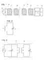
- FIG. 2 is a circuit diagram showing an equivalent circuit of a transmission induction coil according to one embodiment of the disclosure
- FIG. 3 is a circuit diagram showing an equivalent circuit of a power source and a transmission unit according to one embodiment of the disclosure
- FIG. 4 is a circuit diagram showing an equivalent circuit of a reception resonant coil, a reception induction coil, a smoothing circuit, and a load according to one embodiment of the disclosure
- FIG. 5 is a block diagram showing a shielding apparatus according to one embodiment of the disclosure.
- FIG. 6 is a view showing the structure of the wireless power transmission system employing a wireless power transmission apparatus according to one embodiment of the disclosure.
- FIG. 7 is a graph showing the variation in real and imaginary component values of a permeability of a shielding member according to the use frequencies for wireless power transmission.
- FIG. 1 is a view showing a wireless power transmission system according to the embodiment of the disclosure.
- the power generated from a power source 10 is provided to a power transmitting unit 20, such that the power transmitting unit 20 transmits the power using resonance to a power receiving unit 30, which is resonant with the power transmitting unit 20 and has the same resonant frequency value as that of the power transmitting unit 20.
- the power transferred to the power receiving unit 30 is transferred via a rectifier circuit 40 to a load 50.
- the load 50 may be a battery or a predetermined apparatus which needs power.
- the power source 10 is an AC power source for supplying AC power of a predetermined frequency.
- the power transmitting unit 20 includes a transmission induction coil 21 and a transmission resonant coil 22.
- the transmission induction coil 21 is connected to the power source 10, such that AC current flows through the transmission induction coil 21.
- AC current flows through the transmission induction coil 21
- AC current is induced to the transmission resonant coil 22 physically spaced apart from the transmission induction coil 21 due to electromagnetic induction.
- the power transferred to the transmission resonant coil 22 is transmitted using resonance to the power receiving unit 30 which forms a resonance circuit with the power transmitting unit 20.
- the power can be transmitted between two LC circuits, which are impedance-matched with each other, due to resonance.
- the power transmission method using the resonance can transmit the power farther than the power transmission method using the electromagnetic induction with the higher power transmission efficiency.
- the power receiving unit 30 includes a reception resonant coil 31 and a reception induction coil 32.
- the power transmitted from the transmission resonant coil unit 22 is received at the reception resonant coil 31, so that the AC current flows through the reception resonant coil 31.
- the power transmitted to the reception resonant coil 31 is transferred by electromagnetic induction to the reception induction coil 32.
- the power transferred to the reception induction coil 32 is rectified by the rectifier circuit 40 and then transferred to the load 50.
- FIG. 2 is an equivalent circuit diagram of the transmission induction coil 21 according to the embodiment of the disclosure.
- the transmission induction coil 21 may include an inductor L1 and a capacitor C1, and form a circuit having a suitable inductance value and a suitable capacitance value.
- the capacitor C1 may be a variable capacitor.
- the impedance matching can be performed by adjusting a variable capacitor.
- equivalent circuits of the transmission resonant coil 22, the reception resonant coil 31, and the reception induction coil 32 may be equal to that shown in FIG. 2 .
- FIG. 3 is an equivalent circuit diagram of the power source 10 and the power transmitting unit 20 according to the embodiment of the disclosure.
- each of the transmission resonance coil 21 and the transmission resonance coil 22 may include an inductor L1 or L2 and a capacitor C1 or C2 having a predetermined inductance value and a predetermined capacitance value, respectively.
- FIG. 4 is an equivalent circuit diagram of the reception resonant coil 31, the reception induction coil 32, the smoothing circuit 40 and the load 50 according to the embodiment of the disclosure.
- each of the transmission resonant coil 31 and the reception induction coil 32 may include an inductor L3 or L4 and a capacitor C3 or C4 having a predetermined inductance value and a predetermined capacitance value, respectively.
- the smoothing circuit 40 may include a diode D1 and a smoothing capacitor C5 to convert AC power into DC power to be output.
- the load 50 is denoted as a 1.3 V DC power source, the load 50 may be a battery or other devices requiring DC power.
- FIG. 5 is a block diagram showing a shielding apparatus 60 according to one embodiment of the disclosure.
- the shielding apparatus 60 includes first and second shielding units 61 and 62.
- the shielding apparatus 60 is applicable to both of wireless power transmission methods using electromagnetic induction and resonance.
- the shielding apparatus 60 can change the transmission path of a portion of a magnetic field, which is transmitted from the wireless power transmission apparatus 100 to the wireless power reception apparatus 200, or can shield a portion of the magnetic field to be leaked to the outside.
- the first shielding unit 61 can change the transmission path of a portion of the magnetic field produced from the transmission resonance coil 22 of the wireless power transmission apparatus 100.
- the first shielding unit 61 changes the transmission path of the portion of the magnetic field produced from the transmission resonance coil 22 to the wireless power reception apparatus 200, so that the great quantity of the magnetic field can be transmitted to the wireless power reception apparatus 200. In other words, the power transmission efficiency between the wireless power transmission apparatus 100 and the wireless reception apparatus 200 can be increased due to the first shielding unit 61.
- the second shielding unit 62 can shield the magnetic field, which has been produced from the transmission resonance coil 22 and has passed through the first shielding unit 61, from being leaked to the outside.
- the second shielding unit 62 absorbs a portion of the magnetic field, which has passed through the first shielding unit 61, and converts the magnetic field into thermal energy, thereby preventing the magnetic field from being leaked to the outside. If the quantity of a magnetic field to be leaked to the outside is reduced, the magnetic field harmful to the human body is not exposed to the human body.
- the first and second shielding units 61 and 62 include difference types of magnetic substances.
- the first and second shielding units 61 and 62 may include spinel, hexa, sandust, and permalloy magnetic substances.
- the first shielding unit 61 may include the spinel magnetic substance
- the second shielding unit 62 may include the hexa magnetic substance.
- the first shielding unit 61 is not limited to the spinel magnetic substance, but the first shielding unit 61 may include the hexa magnetic substance or the garnet magnetic substance.
- the second shielding unit 62 may include the spinel magnetic substance.
- Table 1 shows composition formulas of the spinel, garnet, and hexa magnetic substances.
- Me* refers at least one selected from the group consisting of cobalt (Co), nickel (Ni), zinc (Zn), copper (C), and manganese (Mn), and R* refers to yttrium (Y) elements.
- the sandust magnetic substance includes the combination of iron (Fe), silicon (Si), and aluminum (Al), and the compositional ratios of the elements are 84%, 10%, and 6%, respectively.
- the permalloy magnetic substance includes the composition of iron (Fe) and nickel (Ni), and the compositional ratios of the elements are 90% and 10%, respectively.
- the first and second shielding units 61 and 62 may have different permeability values.
- the permeability refers to the quantity representing the magnetic property of a material, and, that is, the ratio of the intensity of the magnetic field under a vacuum state to the magnetic flux density produced when the material is magnetized under the influence of the magnetic field.
- the permeability ⁇ 1 of the first shielding unit 61 can be expressed through a complex number having a real component and an imaginary component as shown in Equation 1.
- ⁇ ⁇ 1 ⁇ ⁇ 11 + j ⁇ ⁇ 12
- the real component ⁇ 11 of the permeability ⁇ 1 of the first shielding unit 61 may represent the extent to change (guide) the direction of the magnetic field came into the first shielding unit 61. In other words, as the value of the real component ⁇ 11 is increased, the direction of the magnetic field came into the first shielding unit 61 may be much more changed. As the value of the real component ⁇ 11 is reduced, the direction of the magnetic field came into the first shielding unit 61 may be less changed.
- the imaginary component ⁇ 12 of the permeability ⁇ 1 of the first shielding unit 61 may represent the extent to absorb the magnetic field came into the first shielding unit 61 and convert the magnetic field into thermal energy.
- the great quantity of the magnetic field came into the first shielding unit 61 may be converted into thermal energy to be discharged to the outside.
- the value of the imaginary component ⁇ 12 is reduced, the slight quantity of the magnetic field came into the first shielding unit 61 may be converted into thermal energy to be discharged to the outside.
- the real component ⁇ 11 of the permeability ⁇ 1 of the first shielding unit 61 may be greater than the imaginary component ⁇ 12 of the permeability ⁇ 1 of the first shielding unit 61.
- the first shielding unit 61 mainly performs a function of changing the direction of the magnetic field rather than a function of minimizing the quantity of the magnetic field to be discharged to the outside.
- the real component ⁇ 11 of the permeability ⁇ 1 may be greater than the imaginary component ⁇ 12.
- the ratio of the real component ⁇ 11 of the permeability ⁇ 1 of the first shielding unit 61 to the imaginary component ⁇ 12 of the permeability ⁇ 1 may be in the range from 10:1 to 1000:1.
- the preferable ratio of the real component ⁇ 11 of the permeability ⁇ 1 of the first shielding unit 61 to the imaginary component ⁇ 12 of the permeability ⁇ 1 is at least 10:1, the first shielding unit 61 may more perform a function of changing the transmission path of the magnetic field rather than a function of absorbing the magnetic field and converting the magnetic field into heat to be discharged.
- the first shielding unit 61 may not smoothly change the transmission path of the magnetic field, which is came into the first shielding unit 61, toward the wireless power reception apparatus.
- the first shielding unit 61 may not perform an intrinsic function thereof at the frequency band used for the wireless power transmission due to the characteristic that the permeability of the magnetic material included in the first shielding unit 61 varies according to the frequencies.
- the real component ⁇ 11 of the permeability ⁇ 1 and the imaginary component ⁇ 12 of the permeability ⁇ 1 may have values of about 30 to about 5000 due to the characteristic of materials included in the shielding material.
- the real component ⁇ 21 of the permeability ⁇ 2 of the second shielding unit 62 and the imaginary component ⁇ 22 of the permeability ⁇ 2 may have values of about 30 to about 5000 due to the characteristic of materials included in the shielding material.
- the permeability ⁇ 2 of the second shielding unit 62 may be expressed through the complexity number having real and imaginary components as shown in Equation 2.
- ⁇ ⁇ 2 ⁇ ⁇ 21 + j ⁇ ⁇ 22.
- the real component ⁇ 21 of the permeability ⁇ 2 of the second shielding unit 62 may represent the extent to change (guide) the direction of the magnetic field came into the second shielding unit 62. In other words, as the value of the real component ⁇ 21 is increased, the direction of the magnetic field came into the second shielding unit 62 may be much more changed. As the value of the real component ⁇ 21 is reduced, the direction of the magnetic field came into the second shielding unit 62 may be less changed.
- the imaginary component ⁇ 22 of the permeability ⁇ 2 of the second shielding unit 62 may represent the extent to absorb the magnetic field came into the second shielding unit 62 and convert the magnetic field into thermal energy.
- the great quantity of the magnetic field came into the second shielding unit 62 may be converted into thermal energy to be discharged to the outside.
- the slight quantity of the magnetic field came into the second shielding unit 62 may be converted into thermal energy to be discharged to the outside.
- the imaginary component ⁇ 22 of the permeability ⁇ 2 of the second shielding unit 62 may be greater than the real component ⁇ 21.
- the ratio of the imaginary component ⁇ 22 and the real component ⁇ 21 of the permeability ⁇ 2 of the second shielding unit 62 may be in the range from 1:1 to 10:1. Since the second shielding unit 62 mainly performs a function of minimizing the quantity of the magnetic field to be leaked to the outside rather than the function of changing the direction of the magnetic field, the imaginary component ⁇ 22 of the permeability ⁇ 2 must be greater than the real component ⁇ 21 of the permeability ⁇ 2.
- the second shielding unit 62 may not perform the intrinsic function thereof at the frequency band used for the wireless power transmission due to the characteristic that the permeability of the magnetic material included in the second shielding unit 62 varies according the frequencies.
- the first shielding unit 61 may be bonded to the second shielding unit 62 through a mechanical method such as a compression method or an adhesion method.
- the first and second shielding units 61 and 62 are bonded to each other by preparing the thin plates of the first and second shielding units 61 and 62 in a predetermined form by using a compressor at the room temperature.
- the first and second shielding units 61 and 62 adheres to each other by using the adhesive strength between the interfacial surfaces of the first and second shielding units 61 and 62.
- the first and second shielding units 61 and 62 may be bonded to each other through a thin film deposition method.
- the thin film deposition method is a method in which metal or compound is heated and evaporated under the vacuum state so that the vapor is coated on the surface of a matter in the form of a thin film.
- the thin film deposition method is classified into a physical vapor deposition (PVD) method or a chemical vapor deposition (CVD) method.
- the shielding apparatus 60 may be used in relation to wireless power transmission as described above, the shielding apparatus 60 is applicable to a communication method such as a radio-frequency identification (RFID) method, a near field communication (NFC) method, or a keyless entry method.
- RFID radio-frequency identification
- NFC near field communication
- a transmission apparatus employing the communication method such as the RFID method, the NFC method, or the keyless entry method is used instead of the wireless power transmission apparatus 100.
- FIG. 6 is a view showing the structure of the wireless power transmission system employing the wireless power transmission apparatus according to one embodiment of the disclosure.
- the wireless power transmission system may include the wireless power transmission apparatus 100 and the wireless power reception apparatus 200.
- the wireless power transmission apparatus 100 may include the power transmitting unit 20 and the shielding apparatus 60.
- the power transmitting unit 20 may include the transmission induction coil 21, the transmission resonance coil 22, and a capacitor. The detail thereof has been already described with reference to FIG. 1 .
- the power transmitting unit 20 receives power from the power source 10 to transmit the magnetic field, which is generated from the transmission resonance coil 22, to the reception resonance coil 31 of the wireless power reception apparatus 200 through a non-radiation method.
- the shielding unit 60 includes the first and second shielding units 61 and 62.
- the first shielding unit 61 can change the transmission path of a portion of a magnetic field transmitted from the wireless power transmission apparatus 100 to the wireless power reception apparatus 200, and the second shielding unit 62 can shield a portion of the magnetic field passing through the first shielding unit 61 and exposed to the outside.
- the first shielding unit 61 may include silver representing permeability ⁇ 1 having the real component value ⁇ 11 greater than the imaginary component value ⁇ 12. According to the embodiment, the ratio of the real component ⁇ 11 to the imaginary component ⁇ 12 may be at least 100:1.
- the second shielding unit 62 can shield the magnetic field which has been generated from the transmission resonance coil 22 and has passed through the first shielding unit 61.
- the second shielding unit 62 absorbs a portion of the magnetic field, which has passed through the first shielding unit 61, and converts the portion of the magnetic field into thermal energy, so that the magnetic field can be prevented from being leaked to the outside.
- the second shielding unit 62 may include a material representing permeability ⁇ 2 having the imaginary component value ⁇ 22 greater than the real component value ⁇ 21.
- the first shielding unit 61 can transmit a greater amount of power to the wireless power reception apparatus 200 by changing the direction of the magnetic field generated from the transmission resonance coil 22.
- the second shielding unit 62 absorbs a portion of the magnetic field, which has passed through the first shielding unit 61 and discharges the absorbed of the magnetic field as thermal energy, thereby minimizing the quantity of the magnetic field to be leaked to the outside. If the quantity of the magnetic field to be leaked to the outside is minimized, another device can be prevented from erroneously operating and the harmful magnetic field can be prevented from being exposed to the human body.
- the shielding unit 60 having a multi-layer structure increases the power transmission efficiency to the wireless power reception apparatus 200 while minimizing the quantity of the magnetic field to be leaked to the outside.
- the shielding unit 60 is installed in a transmission apparatus communicating with a reception apparatus using a magnetic field in addition to the wireless power transmission technology, thereby increasing the power transmission efficiency while minimizing the quantity of the magnetic field to be leaked to the outside.
- FIG. 7 is a graph showing the variation in real and imaginary component values of permeability of a shielding material according to the use frequencies for wireless power transmission.
- FIG. 7 is a graph showing the variation characteristic of the permeability of typical ferrites according to the use frequencies for the wireless power transmission.
- the real and imaginary components ⁇ 1 and ⁇ 2 of the permeability ⁇ of the shielding material are varied according to the variation of the use frequency for the wireless power transmission.
- the use frequency is determined, the real and imaginary components of the permeability according to the determined use frequency are determined. Accordingly, a shielding unit employing the shielding material is determined as described with reference to FIG. 5 .
- the shielding material may constitute the second shielding unit 61 for absorbing the magnetic field to discharge heat.
- the curves of the real and imaginary components ⁇ 1 and ⁇ 2 may have various forms according to the materials used as a shielding material. Accordingly, a user can design the shielding unit 60 by selecting a desirable shielding material according to the use frequency.
Landscapes
- Engineering & Computer Science (AREA)
- Power Engineering (AREA)
- Computer Networks & Wireless Communication (AREA)
- Signal Processing (AREA)
- Physics & Mathematics (AREA)
- Electromagnetism (AREA)
- Shielding Devices Or Components To Electric Or Magnetic Fields (AREA)
- Charge And Discharge Circuits For Batteries Or The Like (AREA)
- Near-Field Transmission Systems (AREA)
- Hard Magnetic Materials (AREA)
- Soft Magnetic Materials (AREA)
Applications Claiming Priority (1)
| Application Number | Priority Date | Filing Date | Title |
|---|---|---|---|
| KR1020110108960A KR101209979B1 (ko) | 2011-10-24 | 2011-10-24 | 차폐장치 및 무선전력 송신장치 |
Publications (3)
| Publication Number | Publication Date |
|---|---|
| EP2587497A2 true EP2587497A2 (fr) | 2013-05-01 |
| EP2587497A3 EP2587497A3 (fr) | 2014-05-07 |
| EP2587497B1 EP2587497B1 (fr) | 2019-01-09 |
Family
ID=47146178
Family Applications (1)
| Application Number | Title | Priority Date | Filing Date |
|---|---|---|---|
| EP12188604.8A Active EP2587497B1 (fr) | 2011-10-24 | 2012-10-16 | Appareil de protection et appareil de transmission de puissance sans fil |
Country Status (6)
| Country | Link |
|---|---|
| US (1) | US9595381B2 (fr) |
| EP (1) | EP2587497B1 (fr) |
| JP (2) | JP2013094049A (fr) |
| KR (1) | KR101209979B1 (fr) |
| CN (1) | CN103068212B (fr) |
| TW (1) | TWI552477B (fr) |
Cited By (2)
| Publication number | Priority date | Publication date | Assignee | Title |
|---|---|---|---|---|
| WO2014137902A1 (fr) * | 2013-03-08 | 2014-09-12 | Qualcomm Incorporated | Inducteur séparé couplé à concentration de flux utilisant un matériau hautement perméable |
| TWI572150B (zh) * | 2014-10-20 | 2017-02-21 | 財團法人資訊工業策進會 | 信號發射裝置、訊息產生系統與信號功率調整方法 |
Families Citing this family (13)
| Publication number | Priority date | Publication date | Assignee | Title |
|---|---|---|---|---|
| JP2013192391A (ja) * | 2012-03-14 | 2013-09-26 | Sony Corp | 検知装置、受電装置、送電装置及び非接触給電システム |
| DE102013226226A1 (de) * | 2012-12-21 | 2014-06-26 | Robert Bosch Gmbh | Induktivladespulenvorrichtung |
| US9819228B2 (en) * | 2013-03-01 | 2017-11-14 | Qualcomm Incorporated | Active and adaptive field cancellation for wireless power systems |
| KR102190820B1 (ko) | 2014-01-22 | 2020-12-14 | 엘지이노텍 주식회사 | 무선 충전 기판 및 무선 충전 장치 |
| KR101656260B1 (ko) | 2015-01-05 | 2016-09-09 | 주식회사 아모센스 | 무선충전용 차폐유닛 및 이를 포함하는 무선전력 충전모듈 |
| CN105101767B (zh) * | 2015-07-02 | 2019-04-09 | 宁波微鹅电子科技有限公司 | 电磁屏蔽结构及具有电磁屏蔽结构的电能传输装置 |
| CN105050372B (zh) * | 2015-09-09 | 2019-05-17 | 宁波微鹅电子科技有限公司 | 一种电磁屏蔽层及具有电磁屏蔽层的无线电能传输装置 |
| KR20170092238A (ko) * | 2016-02-03 | 2017-08-11 | 엘지이노텍 주식회사 | 무선 전력 충전을 위한 자성 차폐재 및 무선 전력 수신 장치 |
| US20180090998A1 (en) * | 2016-09-23 | 2018-03-29 | Apple Inc. | Interconnection structures for wireless charging mats |
| WO2019190091A1 (fr) * | 2018-03-28 | 2019-10-03 | 엘지이노텍 주식회사 | Dispositif de charge sans fil pourvu d'une bobine de communication sans fil |
| CN112051460B (zh) * | 2019-06-06 | 2023-06-13 | 南瑞集团有限公司 | 一种无线充电系统电磁安全性评估方法 |
| KR20210119183A (ko) * | 2020-03-24 | 2021-10-05 | 주식회사 아모센스 | 수신 안테나용 자기장 차폐시트 및 이를 포함하는 무선전력 수신모듈 |
| CN115835610A (zh) * | 2021-09-17 | 2023-03-21 | 苹果公司 | 用于无线系统的静电屏蔽件 |
Family Cites Families (34)
| Publication number | Priority date | Publication date | Assignee | Title |
|---|---|---|---|---|
| US5223849A (en) * | 1986-11-25 | 1993-06-29 | Chomerics, Inc. | Broadband electromagnetic energy absorber |
| JPH043401U (fr) * | 1990-04-24 | 1992-01-13 | ||
| JPH0935927A (ja) | 1995-07-20 | 1997-02-07 | Tokin Corp | 複合磁性体及びそれを用いた電磁干渉抑制体 |
| JP3948784B2 (ja) | 1997-05-12 | 2007-07-25 | 北川工業株式会社 | 電磁波減衰用部材 |
| GB2360138A (en) * | 2000-03-06 | 2001-09-12 | Marconi Caswell Ltd | Screens for RF magnetic flux |
| GB2360137A (en) * | 2000-03-06 | 2001-09-12 | Marconi Caswell Ltd | Guides for RF magnetic flux |
| JP2002198850A (ja) * | 2000-12-27 | 2002-07-12 | Sony Corp | 携帯電話機 |
| JP4281858B2 (ja) | 2002-03-29 | 2009-06-17 | ソニー株式会社 | 磁性膜 |
| EP2479866B1 (fr) * | 2002-06-10 | 2018-07-18 | City University of Hong Kong | Chargeur de batterie inductive plane |
| JP2005327245A (ja) * | 2004-12-24 | 2005-11-24 | Nitta Ind Corp | タグ用磁気シールドシートおよびタグ |
| JP2006245950A (ja) * | 2005-03-02 | 2006-09-14 | Sony Corp | 磁芯部材、磁芯部材の製造方法、アンテナモジュール及びこれを備えた携帯情報端末 |
| JP3754446B2 (ja) | 2005-08-04 | 2006-03-15 | ニッタ株式会社 | 磁気シールドシートおよび通信装置 |
| JP2007201113A (ja) * | 2006-01-26 | 2007-08-09 | Yokohama Rubber Co Ltd:The | 高強度電波吸収体 |
| JP2007295558A (ja) * | 2006-03-31 | 2007-11-08 | Nitta Ind Corp | アンテナ通信改善用シート体および電子機器 |
| JP5118394B2 (ja) * | 2007-06-20 | 2013-01-16 | パナソニック株式会社 | 非接触電力伝送機器 |
| JP4605192B2 (ja) | 2007-07-20 | 2011-01-05 | セイコーエプソン株式会社 | コイルユニット及び電子機器 |
| JP2009076513A (ja) * | 2007-09-19 | 2009-04-09 | Yoshi Takaishi | 平面コイル用のシールド構造 |
| JP5332185B2 (ja) | 2007-11-16 | 2013-11-06 | ソニー株式会社 | 磁性粉の製造方法、磁性シートの製造方法及びアンテナモジュールの製造方法 |
| KR101594286B1 (ko) * | 2008-02-22 | 2016-02-15 | 액세스 비지니스 그룹 인터내셔날 엘엘씨 | 유도성 커플링을 위한 자기 위치 설정 시스템 |
| KR101763547B1 (ko) | 2008-03-13 | 2017-07-31 | 액세스 비지니스 그룹 인터내셔날 엘엘씨 | 원격 장치로의 유도 전력 전송 방법 및 원격 장치에 전력을 공급하기 위한 유도 전력 공급장치 |
| KR101094253B1 (ko) | 2008-04-28 | 2011-12-19 | 정춘길 | 무선 전력 수신 장치, 이와 관련된 무선 전력 송신 장치, 그리고, 무선 전력 송수신 시스템 |
| US20110050164A1 (en) * | 2008-05-07 | 2011-03-03 | Afshin Partovi | System and methods for inductive charging, and improvements and uses thereof |
| JP2010072957A (ja) | 2008-09-18 | 2010-04-02 | Daido Steel Co Ltd | Rfidタグ |
| JP5274989B2 (ja) * | 2008-11-12 | 2013-08-28 | 昭和飛行機工業株式会社 | 非接触給電装置 |
| CN101486262A (zh) * | 2009-02-20 | 2009-07-22 | 华中科技大学 | 一种抑制电磁噪声的薄膜材料 |
| JP5431774B2 (ja) * | 2009-04-14 | 2014-03-05 | 富士通テン株式会社 | 無線電力伝送装置および無線電力伝送方法 |
| JP5372610B2 (ja) | 2009-06-08 | 2013-12-18 | Necトーキン株式会社 | 非接触電力伝送装置 |
| CN201533482U (zh) * | 2009-11-18 | 2010-07-21 | 中国人民解放军理工大学工程兵工程学院 | 电磁屏蔽复合板 |
| CN102656648A (zh) * | 2009-12-17 | 2012-09-05 | 丰田自动车株式会社 | 屏蔽装置以及搭载该屏蔽装置的车辆 |
| KR101706693B1 (ko) * | 2009-12-30 | 2017-02-14 | 삼성전자주식회사 | 근접 필드 포커싱을 이용한 무선 전력 전송 장치 |
| JP5211088B2 (ja) | 2010-02-12 | 2013-06-12 | トヨタ自動車株式会社 | 給電装置および車両給電システム |
| JP5659504B2 (ja) | 2010-03-02 | 2015-01-28 | 富士通株式会社 | 電磁波特性改善用シート体 |
| JP5644521B2 (ja) * | 2011-01-14 | 2014-12-24 | ソニー株式会社 | 信号伝送装置、及び、電子機器 |
| EP2858470B1 (fr) * | 2012-06-04 | 2023-04-12 | Amosense Co., Ltd. | Feuille de blindage de champ magnétique pour numériseur graphique, procédé de fabrication de celle-ci, et dispositif de terminal portable utilisant celle-ci |
-
2011
- 2011-10-24 KR KR1020110108960A patent/KR101209979B1/ko not_active Expired - Fee Related
-
2012
- 2012-10-12 TW TW101137779A patent/TWI552477B/zh not_active IP Right Cessation
- 2012-10-16 EP EP12188604.8A patent/EP2587497B1/fr active Active
- 2012-10-18 JP JP2012230481A patent/JP2013094049A/ja active Pending
- 2012-10-24 CN CN201210408846.XA patent/CN103068212B/zh not_active Expired - Fee Related
- 2012-10-24 US US13/659,008 patent/US9595381B2/en active Active - Reinstated
-
2015
- 2015-04-16 JP JP2015084536A patent/JP5960317B2/ja not_active Expired - Fee Related
Non-Patent Citations (1)
| Title |
|---|
| None |
Cited By (2)
| Publication number | Priority date | Publication date | Assignee | Title |
|---|---|---|---|---|
| WO2014137902A1 (fr) * | 2013-03-08 | 2014-09-12 | Qualcomm Incorporated | Inducteur séparé couplé à concentration de flux utilisant un matériau hautement perméable |
| TWI572150B (zh) * | 2014-10-20 | 2017-02-21 | 財團法人資訊工業策進會 | 信號發射裝置、訊息產生系統與信號功率調整方法 |
Also Published As
| Publication number | Publication date |
|---|---|
| US20130099589A1 (en) | 2013-04-25 |
| TWI552477B (zh) | 2016-10-01 |
| JP5960317B2 (ja) | 2016-08-02 |
| EP2587497A3 (fr) | 2014-05-07 |
| JP2013094049A (ja) | 2013-05-16 |
| CN103068212B (zh) | 2017-07-07 |
| US9595381B2 (en) | 2017-03-14 |
| KR101209979B1 (ko) | 2012-12-07 |
| JP2015173593A (ja) | 2015-10-01 |
| TW201322583A (zh) | 2013-06-01 |
| EP2587497B1 (fr) | 2019-01-09 |
| CN103068212A (zh) | 2013-04-24 |
Similar Documents
| Publication | Publication Date | Title |
|---|---|---|
| US9595381B2 (en) | Shielding apparatus and wireless power transmission apparatus | |
| US11025070B2 (en) | Device having a multimode antenna with at least one conductive wire with a plurality of turns | |
| US11955809B2 (en) | Single structure multi mode antenna for wireless power transmission incorporating a selection circuit | |
| US9362985B2 (en) | Portable apparatus and feed system | |
| US9948129B2 (en) | Single structure multi mode antenna for wireless power transmission using magnetic field coupling having an internal switch circuit | |
| US10636563B2 (en) | Method of fabricating a single structure multi mode antenna for wireless power transmission using magnetic field coupling | |
| US9941743B2 (en) | Single structure multi mode antenna having a unitary body construction for wireless power transmission using magnetic field coupling | |
| EP3404793B1 (fr) | Appareil de transmission de puissance sans fil | |
| US9960628B2 (en) | Single structure multi mode antenna having a single layer structure with coils on opposing sides for wireless power transmission using magnetic field coupling | |
| US9941590B2 (en) | Single structure multi mode antenna for wireless power transmission using magnetic field coupling having magnetic shielding | |
| US11205848B2 (en) | Method of providing a single structure multi mode antenna having a unitary body construction for wireless power transmission using magnetic field coupling | |
| US9960629B2 (en) | Method of operating a single structure multi mode antenna for wireless power transmission using magnetic field coupling | |
| US10931151B2 (en) | Combination antenna module and portable electronic device including same | |
| US9941729B2 (en) | Single layer multi mode antenna for wireless power transmission using magnetic field coupling | |
| EP2582064B1 (fr) | Répéteur de puissance sans fil | |
| US10692648B2 (en) | Magnetic field shielding structure and mobile device including the magnetic field structure | |
| TW201433009A (zh) | 軟磁性層、接收天線、以及包含前者之無線電力接收裝置 | |
| KR20180132739A (ko) | 노이즈 억제 조립체 | |
| KR101856564B1 (ko) | 콤보 안테나모듈 및 이를 포함하는 휴대용 전자장치 |
Legal Events
| Date | Code | Title | Description |
|---|---|---|---|
| PUAI | Public reference made under article 153(3) epc to a published international application that has entered the european phase |
Free format text: ORIGINAL CODE: 0009012 |
|
| AK | Designated contracting states |
Kind code of ref document: A2 Designated state(s): AL AT BE BG CH CY CZ DE DK EE ES FI FR GB GR HR HU IE IS IT LI LT LU LV MC MK MT NL NO PL PT RO RS SE SI SK SM TR |
|
| AX | Request for extension of the european patent |
Extension state: BA ME |
|
| PUAL | Search report despatched |
Free format text: ORIGINAL CODE: 0009013 |
|
| AK | Designated contracting states |
Kind code of ref document: A3 Designated state(s): AL AT BE BG CH CY CZ DE DK EE ES FI FR GB GR HR HU IE IS IT LI LT LU LV MC MK MT NL NO PL PT RO RS SE SI SK SM TR |
|
| AX | Request for extension of the european patent |
Extension state: BA ME |
|
| RIC1 | Information provided on ipc code assigned before grant |
Ipc: H01F 27/36 20060101ALI20140328BHEP Ipc: H01F 38/14 20060101AFI20140328BHEP Ipc: H02J 5/00 20060101ALI20140328BHEP Ipc: H04B 5/00 20060101ALI20140328BHEP Ipc: H05K 9/00 20060101ALI20140328BHEP Ipc: H02J 7/02 20060101ALI20140328BHEP |
|
| 17P | Request for examination filed |
Effective date: 20140930 |
|
| RBV | Designated contracting states (corrected) |
Designated state(s): AL AT BE BG CH CY CZ DE DK EE ES FI FR GB GR HR HU IE IS IT LI LT LU LV MC MK MT NL NO PL PT RO RS SE SI SK SM TR |
|
| STAA | Information on the status of an ep patent application or granted ep patent |
Free format text: STATUS: EXAMINATION IS IN PROGRESS |
|
| 17Q | First examination report despatched |
Effective date: 20170215 |
|
| RAP1 | Party data changed (applicant data changed or rights of an application transferred) |
Owner name: LG INNOTEK CO., LTD. |
|
| GRAP | Despatch of communication of intention to grant a patent |
Free format text: ORIGINAL CODE: EPIDOSNIGR1 |
|
| STAA | Information on the status of an ep patent application or granted ep patent |
Free format text: STATUS: GRANT OF PATENT IS INTENDED |
|
| INTG | Intention to grant announced |
Effective date: 20180727 |
|
| GRAS | Grant fee paid |
Free format text: ORIGINAL CODE: EPIDOSNIGR3 |
|
| GRAA | (expected) grant |
Free format text: ORIGINAL CODE: 0009210 |
|
| STAA | Information on the status of an ep patent application or granted ep patent |
Free format text: STATUS: THE PATENT HAS BEEN GRANTED |
|
| AK | Designated contracting states |
Kind code of ref document: B1 Designated state(s): AL AT BE BG CH CY CZ DE DK EE ES FI FR GB GR HR HU IE IS IT LI LT LU LV MC MK MT NL NO PL PT RO RS SE SI SK SM TR |
|
| REG | Reference to a national code |
Ref country code: GB Ref legal event code: FG4D |
|
| REG | Reference to a national code |
Ref country code: CH Ref legal event code: EP Ref country code: AT Ref legal event code: REF Ref document number: 1088341 Country of ref document: AT Kind code of ref document: T Effective date: 20190115 |
|
| REG | Reference to a national code |
Ref country code: DE Ref legal event code: R096 Ref document number: 602012055632 Country of ref document: DE |
|
| REG | Reference to a national code |
Ref country code: IE Ref legal event code: FG4D |
|
| REG | Reference to a national code |
Ref country code: NL Ref legal event code: MP Effective date: 20190109 |
|
| REG | Reference to a national code |
Ref country code: LT Ref legal event code: MG4D |
|
| PG25 | Lapsed in a contracting state [announced via postgrant information from national office to epo] |
Ref country code: NL Free format text: LAPSE BECAUSE OF FAILURE TO SUBMIT A TRANSLATION OF THE DESCRIPTION OR TO PAY THE FEE WITHIN THE PRESCRIBED TIME-LIMIT Effective date: 20190109 |
|
| REG | Reference to a national code |
Ref country code: AT Ref legal event code: MK05 Ref document number: 1088341 Country of ref document: AT Kind code of ref document: T Effective date: 20190109 |
|
| PG25 | Lapsed in a contracting state [announced via postgrant information from national office to epo] |
Ref country code: PL Free format text: LAPSE BECAUSE OF FAILURE TO SUBMIT A TRANSLATION OF THE DESCRIPTION OR TO PAY THE FEE WITHIN THE PRESCRIBED TIME-LIMIT Effective date: 20190109 Ref country code: FI Free format text: LAPSE BECAUSE OF FAILURE TO SUBMIT A TRANSLATION OF THE DESCRIPTION OR TO PAY THE FEE WITHIN THE PRESCRIBED TIME-LIMIT Effective date: 20190109 Ref country code: LT Free format text: LAPSE BECAUSE OF FAILURE TO SUBMIT A TRANSLATION OF THE DESCRIPTION OR TO PAY THE FEE WITHIN THE PRESCRIBED TIME-LIMIT Effective date: 20190109 Ref country code: SE Free format text: LAPSE BECAUSE OF FAILURE TO SUBMIT A TRANSLATION OF THE DESCRIPTION OR TO PAY THE FEE WITHIN THE PRESCRIBED TIME-LIMIT Effective date: 20190109 Ref country code: PT Free format text: LAPSE BECAUSE OF FAILURE TO SUBMIT A TRANSLATION OF THE DESCRIPTION OR TO PAY THE FEE WITHIN THE PRESCRIBED TIME-LIMIT Effective date: 20190509 Ref country code: NO Free format text: LAPSE BECAUSE OF FAILURE TO SUBMIT A TRANSLATION OF THE DESCRIPTION OR TO PAY THE FEE WITHIN THE PRESCRIBED TIME-LIMIT Effective date: 20190409 Ref country code: ES Free format text: LAPSE BECAUSE OF FAILURE TO SUBMIT A TRANSLATION OF THE DESCRIPTION OR TO PAY THE FEE WITHIN THE PRESCRIBED TIME-LIMIT Effective date: 20190109 |
|
| PG25 | Lapsed in a contracting state [announced via postgrant information from national office to epo] |
Ref country code: GR Free format text: LAPSE BECAUSE OF FAILURE TO SUBMIT A TRANSLATION OF THE DESCRIPTION OR TO PAY THE FEE WITHIN THE PRESCRIBED TIME-LIMIT Effective date: 20190410 Ref country code: BG Free format text: LAPSE BECAUSE OF FAILURE TO SUBMIT A TRANSLATION OF THE DESCRIPTION OR TO PAY THE FEE WITHIN THE PRESCRIBED TIME-LIMIT Effective date: 20190409 Ref country code: RS Free format text: LAPSE BECAUSE OF FAILURE TO SUBMIT A TRANSLATION OF THE DESCRIPTION OR TO PAY THE FEE WITHIN THE PRESCRIBED TIME-LIMIT Effective date: 20190109 Ref country code: LV Free format text: LAPSE BECAUSE OF FAILURE TO SUBMIT A TRANSLATION OF THE DESCRIPTION OR TO PAY THE FEE WITHIN THE PRESCRIBED TIME-LIMIT Effective date: 20190109 Ref country code: IS Free format text: LAPSE BECAUSE OF FAILURE TO SUBMIT A TRANSLATION OF THE DESCRIPTION OR TO PAY THE FEE WITHIN THE PRESCRIBED TIME-LIMIT Effective date: 20190509 Ref country code: HR Free format text: LAPSE BECAUSE OF FAILURE TO SUBMIT A TRANSLATION OF THE DESCRIPTION OR TO PAY THE FEE WITHIN THE PRESCRIBED TIME-LIMIT Effective date: 20190109 |
|
| REG | Reference to a national code |
Ref country code: DE Ref legal event code: R097 Ref document number: 602012055632 Country of ref document: DE |
|
| PG25 | Lapsed in a contracting state [announced via postgrant information from national office to epo] |
Ref country code: AL Free format text: LAPSE BECAUSE OF FAILURE TO SUBMIT A TRANSLATION OF THE DESCRIPTION OR TO PAY THE FEE WITHIN THE PRESCRIBED TIME-LIMIT Effective date: 20190109 Ref country code: AT Free format text: LAPSE BECAUSE OF FAILURE TO SUBMIT A TRANSLATION OF THE DESCRIPTION OR TO PAY THE FEE WITHIN THE PRESCRIBED TIME-LIMIT Effective date: 20190109 Ref country code: DK Free format text: LAPSE BECAUSE OF FAILURE TO SUBMIT A TRANSLATION OF THE DESCRIPTION OR TO PAY THE FEE WITHIN THE PRESCRIBED TIME-LIMIT Effective date: 20190109 Ref country code: IT Free format text: LAPSE BECAUSE OF FAILURE TO SUBMIT A TRANSLATION OF THE DESCRIPTION OR TO PAY THE FEE WITHIN THE PRESCRIBED TIME-LIMIT Effective date: 20190109 Ref country code: SK Free format text: LAPSE BECAUSE OF FAILURE TO SUBMIT A TRANSLATION OF THE DESCRIPTION OR TO PAY THE FEE WITHIN THE PRESCRIBED TIME-LIMIT Effective date: 20190109 Ref country code: EE Free format text: LAPSE BECAUSE OF FAILURE TO SUBMIT A TRANSLATION OF THE DESCRIPTION OR TO PAY THE FEE WITHIN THE PRESCRIBED TIME-LIMIT Effective date: 20190109 Ref country code: CZ Free format text: LAPSE BECAUSE OF FAILURE TO SUBMIT A TRANSLATION OF THE DESCRIPTION OR TO PAY THE FEE WITHIN THE PRESCRIBED TIME-LIMIT Effective date: 20190109 Ref country code: RO Free format text: LAPSE BECAUSE OF FAILURE TO SUBMIT A TRANSLATION OF THE DESCRIPTION OR TO PAY THE FEE WITHIN THE PRESCRIBED TIME-LIMIT Effective date: 20190109 |
|
| PLBE | No opposition filed within time limit |
Free format text: ORIGINAL CODE: 0009261 |
|
| STAA | Information on the status of an ep patent application or granted ep patent |
Free format text: STATUS: NO OPPOSITION FILED WITHIN TIME LIMIT |
|
| PG25 | Lapsed in a contracting state [announced via postgrant information from national office to epo] |
Ref country code: SM Free format text: LAPSE BECAUSE OF FAILURE TO SUBMIT A TRANSLATION OF THE DESCRIPTION OR TO PAY THE FEE WITHIN THE PRESCRIBED TIME-LIMIT Effective date: 20190109 |
|
| 26N | No opposition filed |
Effective date: 20191010 |
|
| PG25 | Lapsed in a contracting state [announced via postgrant information from national office to epo] |
Ref country code: SI Free format text: LAPSE BECAUSE OF FAILURE TO SUBMIT A TRANSLATION OF THE DESCRIPTION OR TO PAY THE FEE WITHIN THE PRESCRIBED TIME-LIMIT Effective date: 20190109 |
|
| PG25 | Lapsed in a contracting state [announced via postgrant information from national office to epo] |
Ref country code: TR Free format text: LAPSE BECAUSE OF FAILURE TO SUBMIT A TRANSLATION OF THE DESCRIPTION OR TO PAY THE FEE WITHIN THE PRESCRIBED TIME-LIMIT Effective date: 20190109 |
|
| PG25 | Lapsed in a contracting state [announced via postgrant information from national office to epo] |
Ref country code: MC Free format text: LAPSE BECAUSE OF FAILURE TO SUBMIT A TRANSLATION OF THE DESCRIPTION OR TO PAY THE FEE WITHIN THE PRESCRIBED TIME-LIMIT Effective date: 20190109 |
|
| REG | Reference to a national code |
Ref country code: CH Ref legal event code: PL |
|
| PG25 | Lapsed in a contracting state [announced via postgrant information from national office to epo] |
Ref country code: LU Free format text: LAPSE BECAUSE OF NON-PAYMENT OF DUE FEES Effective date: 20191016 Ref country code: LI Free format text: LAPSE BECAUSE OF NON-PAYMENT OF DUE FEES Effective date: 20191031 Ref country code: CH Free format text: LAPSE BECAUSE OF NON-PAYMENT OF DUE FEES Effective date: 20191031 |
|
| REG | Reference to a national code |
Ref country code: BE Ref legal event code: MM Effective date: 20191031 |
|
| PG25 | Lapsed in a contracting state [announced via postgrant information from national office to epo] |
Ref country code: BE Free format text: LAPSE BECAUSE OF NON-PAYMENT OF DUE FEES Effective date: 20191031 |
|
| GBPC | Gb: european patent ceased through non-payment of renewal fee |
Effective date: 20191016 |
|
| PG25 | Lapsed in a contracting state [announced via postgrant information from national office to epo] |
Ref country code: IE Free format text: LAPSE BECAUSE OF NON-PAYMENT OF DUE FEES Effective date: 20191016 Ref country code: GB Free format text: LAPSE BECAUSE OF NON-PAYMENT OF DUE FEES Effective date: 20191016 Ref country code: FR Free format text: LAPSE BECAUSE OF NON-PAYMENT OF DUE FEES Effective date: 20191031 |
|
| REG | Reference to a national code |
Ref country code: DE Ref legal event code: R082 Ref document number: 602012055632 Country of ref document: DE Representative=s name: PETERREINS SCHLEY PATENT- UND RECHTSANWAELTE P, DE |
|
| REG | Reference to a national code |
Ref country code: DE Ref legal event code: R081 Ref document number: 602012055632 Country of ref document: DE Owner name: NERA INNOVATIONS LTD., IE Free format text: FORMER OWNER: LG INNOTEK CO., LTD., SEOUL, KR Ref country code: DE Ref legal event code: R082 Ref document number: 602012055632 Country of ref document: DE Representative=s name: PETERREINS SCHLEY PATENT- UND RECHTSANWAELTE P, DE Ref country code: DE Ref legal event code: R081 Ref document number: 602012055632 Country of ref document: DE Owner name: SCRAMOGE TECHNOLOGY LIMITED, IE Free format text: FORMER OWNER: LG INNOTEK CO., LTD., SEOUL, KR |
|
| PG25 | Lapsed in a contracting state [announced via postgrant information from national office to epo] |
Ref country code: CY Free format text: LAPSE BECAUSE OF FAILURE TO SUBMIT A TRANSLATION OF THE DESCRIPTION OR TO PAY THE FEE WITHIN THE PRESCRIBED TIME-LIMIT Effective date: 20190109 |
|
| PG25 | Lapsed in a contracting state [announced via postgrant information from national office to epo] |
Ref country code: HU Free format text: LAPSE BECAUSE OF FAILURE TO SUBMIT A TRANSLATION OF THE DESCRIPTION OR TO PAY THE FEE WITHIN THE PRESCRIBED TIME-LIMIT; INVALID AB INITIO Effective date: 20121016 Ref country code: MT Free format text: LAPSE BECAUSE OF FAILURE TO SUBMIT A TRANSLATION OF THE DESCRIPTION OR TO PAY THE FEE WITHIN THE PRESCRIBED TIME-LIMIT Effective date: 20190109 |
|
| PG25 | Lapsed in a contracting state [announced via postgrant information from national office to epo] |
Ref country code: MK Free format text: LAPSE BECAUSE OF FAILURE TO SUBMIT A TRANSLATION OF THE DESCRIPTION OR TO PAY THE FEE WITHIN THE PRESCRIBED TIME-LIMIT Effective date: 20190109 |
|
| REG | Reference to a national code |
Ref country code: DE Ref legal event code: R081 Ref document number: 602012055632 Country of ref document: DE Owner name: NERA INNOVATIONS LTD., IE Free format text: FORMER OWNER: SCRAMOGE TECHNOLOGY LIMITED, DUBLIN, IE |
|
| PGFP | Annual fee paid to national office [announced via postgrant information from national office to epo] |
Ref country code: DE Payment date: 20250919 Year of fee payment: 14 |