EP2587611A2 - Stromerzeugungssystem mit vorhersagbarer Steuervorrichtung zum Reduzieren der Beeinflussung von wettervariablen Faktoren - Google Patents
Stromerzeugungssystem mit vorhersagbarer Steuervorrichtung zum Reduzieren der Beeinflussung von wettervariablen Faktoren Download PDFInfo
- Publication number
- EP2587611A2 EP2587611A2 EP12187660.1A EP12187660A EP2587611A2 EP 2587611 A2 EP2587611 A2 EP 2587611A2 EP 12187660 A EP12187660 A EP 12187660A EP 2587611 A2 EP2587611 A2 EP 2587611A2
- Authority
- EP
- European Patent Office
- Prior art keywords
- power
- array
- control strategy
- generation system
- generators
- Prior art date
- Legal status (The legal status is an assumption and is not a legal conclusion. Google has not performed a legal analysis and makes no representation as to the accuracy of the status listed.)
- Granted
Links
Images



Classifications
-
- H—ELECTRICITY
- H02—GENERATION; CONVERSION OR DISTRIBUTION OF ELECTRIC POWER
- H02J—ELECTRIC POWER NETWORKS; CIRCUIT ARRANGEMENTS OR SYSTEMS FOR SUPPLYING OR DISTRIBUTING ELECTRIC POWER; SYSTEMS FOR STORING ELECTRIC ENERGY
- H02J3/00—Circuit arrangements for AC mains or AC distribution networks
- H02J3/38—Arrangements for feeding a single network from two or more generators or sources in parallel; Arrangements for feeding already energised networks from additional generators or sources in parallel
Definitions
- the present invention is generally related to power generation, as may involve a power generation system for generating electrical power, which varies in response to one or more weather-varying factors, such as solar irradiance, temperature, wind, and more particularly to predictive control apparatus and techniques to reduce influences of such weather-varying factors.
- a power generation system for generating electrical power which varies in response to one or more weather-varying factors, such as solar irradiance, temperature, wind, and more particularly to predictive control apparatus and techniques to reduce influences of such weather-varying factors.
- the weather-induced variability of the natural resource may cause challenges at various levels, such as at a component level (e.g., inverter), at a subsystem level, at a distribution level as well as on the larger power grid.
- a component level e.g., inverter
- a subsystem level e.g., at a distribution level as well as on the larger power grid.
- a power generation system for generating electrical power, which varies in response to at least one weather-varying factor.
- the system may include an array of power generators subject to the weather-varying factor.
- the array of power generators may be disposed over respective locations on a field.
- At least one inverter may be coupled to the array of power generators.
- a module may be configured to predict over a time horizon at least one power-generating condition for the array of power generators.
- a controller may be configured to anticipatorily adjust a control strategy regarding operation of the component and/or subsystem of the power generation system based on the predicted power-generating condition for the array of power generators over the time horizon.
- the control strategy may be a cooling control strategy for the inverter based on the predicted power-generating condition for the array of power generators over the time horizon.
- an apparatus which may include a module configured to predict over a time horizon at least one power-generating condition for an array of power generators.
- the apparatus may further include a controller configured to anticipatorily adjust a control strategy regarding operation of at least one component and/or subsystem of the power generation system based on the predicted power-generating condition for the array of power generators over the time horizon.
- a power generation system for generating electrical power, which varies in response to at least one weather-varying factor.
- the system may include an array of power generators subject to the weather-varying factor.
- a module may be configured to predict over a time horizon at least one power-generating condition for the array of power generators.
- a controller may be configured to anticipatorily adjust a control strategy regarding operation of the component and/or subsystem of the power generation system based on the predicted power-generating condition for the array of power generators over the time horizon.
- FIG.1 is a schematic representation of an example embodiment of a power generation system 10 for generating electrical power, which may vary in response to one or more weather-varying factors 11, such as solar irradiance, wind, temperature, etc.
- An array of power generators 12 may be subject to such weather-varying factors.
- power generators 12 may comprise an array of photovoltaic (PV) modules.
- PV photovoltaic
- Solar irradiance may for example vary based on varying cloud conditions, which can lead to changes in the power generating conditions of the array of photovoltaic modules.
- power generators 12 may comprise an array of wind turbines. Varying wind conditions can lead to changes in the power generating conditions of the array of wind turbines. Regardless of the specific modality, the array of power generators 12 may be disposed over respective locations (e.g., spaced-apart locations) on a field 14, such as a utility-scale solar farm, and/or a utility-scale wind park, as may involve a relatively large surface area (e.g., potentially hundreds of acres).
- a field 14 such as a utility-scale solar farm, and/or a utility-scale wind park
- one or more inverters 16 may be coupled to the array of power generators 12.
- photovoltaic arrays naturally produce direct current (DC) power output when exposed to solar irradiance.
- one or more inverters may be used for converting the DC output from the photovoltaic array to an AC signal appropriate for coupling to a power grid 15.
- wind turbine generators can generate AC power output.
- the frequency and phase of the wind turbine output may depend, respectively, on the speed of rotation and position of a rotor within the turbine generator.
- the AC power produced by the wind power system may be initially rectified to produce an intermediate DC power, which is then transformed to AC power via one or more inverters to match the line frequency and phase of power grid 15.
- a predictive module 18 may be configured in accordance with aspects of the present invention to predict over a time horizon, as for example may range from seconds to several hours, at least one power-generating condition for the array of power generators 12.
- predictive module 18 may be responsive to weather observations, as may be obtained from a sensor suite 20 and/or weather forecasts, as may be obtained from weather data services, in combination with model data of the power generators to predict the power-generating condition for the array of power generators 12.
- predictive module 18 may be responsive to historical weather data as may be stored in a database 22.
- a controller 24 may be configured to anticipatorily adjust a control strategy regarding operation of at least one subsystem and/or component of the power generation system based on the predicted power-generating condition for the array of power generators over the time horizon.
- the control strategy may be a cooling control strategy for inverter 16, as may be implemented by way of a cooling subsystem 17, based on the predicted power-generating condition for the array of power generators 12 over the time horizon.
- ⁇ T temperature fluctuations
- IGBT Insulated Gate Bipolar Transistor
- the predicted power-generating condition can be used for instance to effectively deal with relatively long delays that may be part of the physical response of a given component (e.g., thermal inertia in the case of inverter cooling).
- a given component e.g., thermal inertia in the case of inverter cooling.
- anticipatorily adjusting a control strategy for operating a given component before a change in the power-generating condition of the array of power generators takes effect e.g., cloud covering the array
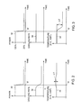
- FIG. 2 shows a sequence of respective plots, which can be used to illustrate an example anticipatory adjusting of a cooling rate for inverter cooling and an example temperature response for the power device (e.g., IGBT), which results from such anticipatory adjusting of the inverter cooling rate.
- Plot 30 indicates a predicted change over a time horizon in the power-generating condition for the array of power generators. For example, at time t2, predictive module 18 ( FIG. 1 ) predicts a drop in the amount of power to be produced by the array of power generators.
- Plot 32 illustrates an anticipatory cooling rate adjustment, as may be commanded by controller 24 ( FIG. 1 ) starting at time t1 in anticipation of the predicted power drop at time t2.
- Plot 34 illustrates an example temperature response of an example power device in the inverter. Note the relatively small maximum ⁇ T in plot 34.
- temperature response 34' corresponds to a constant cooling rate, as indicated by plot 36 in FIG. 3 while temperature responses 34" and 34"' respectively correspond to proportional and overproportional cooling rate adjustments, as respectively indicated by plots 38a and 38b in FIG. 4 .
- the cooling strategy to affect the temperature of the power devices may include one or more of the following strategies: adjusting a switching frequency of the semiconductor power devices, adjusting the amount of power generated by the power generator, and/or adjusting the amount of power to be converted by the inverter.
- adjusting a switching frequency of the semiconductor power devices adjusting the amount of power generated by the power generator, and/or adjusting the amount of power to be converted by the inverter.
- higher switching frequency generally results in higher switching losses and thus results in incremental heating of the power device.
- lower switching frequencies generally results in lower switching losses and thus result in incremental cooling of the power semiconductor device.
- the generated power by the PV module will drop, and thus the temperature of the power semiconductor device in the inverter will drop.
- One example way to compensate for this power generating condition would be increase the switching frequency of the semiconductor switching device to incrementally heat the power switching device and thus reduce the magnitude of the temperature drop.
- the involved time constants are relatively short and this cooling technique may be used to adjust the temperature of the semiconductor switching device relatively quickly.
- FIGs. 5-7 illustrate plots corresponding to various example predictions over a time horizon regarding power-generating conditions for the array of power generators 12. It will be appreciated that in accordance with further aspects of the present invention, the control strategy to be used may be adapted based on the specific characteristics of the predicted power-generating condition for the array of power generators.
- plot 40 represents a prediction indicative of a relatively long duration (represented by line 42) of a shift (e.g., power drop) in the amount of power generated by the array of power generators.
- plot 44 shown in FIG. 6
- plot 44 illustrates a prediction indicative of a relatively short duration (represented by line 46) of a shift (e.g., transient shift) in the amount of power generated by the array of power generators.
- plot 48 represents a prediction indicative of a condition corresponding to intermittent fluctuations over a relatively long time interval (represented by line 50) of the power level generated by the array of power generators.
- the control strategy to be performed may be adapted based on the characteristics of the predicted power-generating condition for the array of power generators. For example, in the example case of a control strategy for inverter cooling, and presuming the predicted reduction of power is relatively long, as illustrated in FIG. 5 , then an anticipatory adjustment may be implemented to the inverter cooling rate, as discussed in the context of FIG. 2 . However, if the predicted reduction of power is relatively short, such as the transient drop illustrated in FIG. 6 , then one may decide not to adjust the cooling strategy since, in this example case, one may choose to rely on the thermal inertia of the system to smooth the ⁇ t fluctuation that may develop from the transient power drop.
- the ability to predict a power-generating condition for the array of power generators may be formulated as an optimal control problem where an appropriate control profile (e.g., cooling profile) may be optimized to ensure minimal or reduced variation of the variable being controlled, such as thermal variation for the power switch devices of inverter 16.
- an appropriate control profile e.g., cooling profile
- inverter 16 may include a maximum power point tracker 19 (MPPT), as shown in FIG. 1 .
- MPPT maximum power point tracker 19
- the MPPP tracking strategies may be anticipatorily adjusted based on the predicted power-generating condition for the array of power generators over the time horizon (e.g., upcoming cloud situation).
- an example current current/voltage (I/V) curve of the PV modules may develop two local maxima during a shading condition. See FIG. 8 .
- the MPPT could sub-optimally track a maximum local power, which is not a global maximum.
- a global voltage sweep could be performed to appropriately identify the global maximum.
- performing such a global voltage sweep tends to reduce inverter efficiency since the PV array/inverter circuitry is operated during the sweep in a non-optimal manner. Thus, it would be desirable to avoid performing unnecessary voltage sweeps.
- the predicted power-generating condition may be used to improve operation of the MPPT. For example, if the predicted power-generating condition is as illustrated in FIG. 5 , (e.g., lasting shading condition), then the tracking strategy may be to perform the global voltage sweep to identify the global maximum. Conversely, if the predicted power generating condition is as illustrated in FIG. 6 , (e.g., transient shading condition), or if the predicted power generating condition is as illustrated in FIG. 7 , (e.g., undefined irradiance condition) then in either case the control strategy may be not to perform the global voltage sweep.
- the foregoing description should be construed as an example MPPT tracking strategy that may benefit from aspects of the present invention and should not be construed in a limiting sense.
- Electrical storage devices 26 may comprise at least one of the following energy storage devices: rechargeable batteries, capacitor banks, inductors, and/or super-capacitors.
- One example factor that can influence the life-time expectancy of an electrical storage device, such as a rechargeable battery may be the number of cycles (e.g., from a loaded condition to a discharged condition and so on) the electrical storage device experiences over time.
- the predicted power-generating conditions for the array of power generators 12 may be processed to determine a cycling strategy for the electrical storage devices optimally configured to reduce the number of cycles experienced by the electrical storage device over time.
- the predicted power-generating condition for the array of power generators 12 is one of reduced power generation, then one may anticipatorily ensure that the majority of the electrical storage devices are appropriately charged prior to the occurrence of the reduced power generation. Conversely, if the predicted power-generating condition for the array of power generators 12 is one of increased power generation, then one may anticipatorily ensure that the majority of the electrical storage devices are appropriately discharged prior to the occurrence of the increased power generation.
- the voltage level in distribution systems may often be controlled by transformers with mechanical switches configured to change the effective number of turns of the transformer.
- This may involve a tap-changer, which is typically mounted on a lower current side.
- One example factor that can influence the life-time expectancy of the tap changer may be the number of tap-changing operations performed by the tap changer over time.
- the predicted power-generating conditions for the array of power generators 12 may be processed to determine a tap- changing strategy for the tap changer optimally configured to reduce the number of tap-changing operations experienced by the tap changer over time and thus increase the life expectancy of the tap-changer.
- main circuit breaker 28 may be set to an electrically-closed condition each time the power-generation system changes to an operational state from a standby condition and vice versa. That is, main circuit breaker 28 may be set to an electrically-open condition each time the power-generation system changes to the standby state from the operational condition.
- One example factor that can influence the life-time expectancy of the main circuit breaker may be the number of on-off switching operations performed by the main circuit breaker.
- the predicted power-generating conditions for the array of power generators 12 may be processed to determine an on-off switching strategy for the main circuit breaker optimally configured to reduce the number of on-off switching operations experienced by the main circuit breaker and thus increase the life expectancy of the main circuit breaker.
- aspects of the present invention may provide one or more of the following advantages: Increase inverter lifetime and reliability; increase inverter efficiency; improved MPPT tracking strategies in systems involving PV energy generation; increase lifetime of step changers in distribution grids for voltage controls; increase lifetime of circuit breakers and/or energy storage devices, as may be part of an energy management subsystem.
Landscapes
- Engineering & Computer Science (AREA)
- Power Engineering (AREA)
- Supply And Distribution Of Alternating Current (AREA)
Applications Claiming Priority (1)
| Application Number | Priority Date | Filing Date | Title |
|---|---|---|---|
| US13/273,328 US8624411B2 (en) | 2011-10-14 | 2011-10-14 | Power generation system including predictive control apparatus to reduce influences of weather-varying factors |
Publications (3)
| Publication Number | Publication Date |
|---|---|
| EP2587611A2 true EP2587611A2 (de) | 2013-05-01 |
| EP2587611A3 EP2587611A3 (de) | 2014-04-30 |
| EP2587611B1 EP2587611B1 (de) | 2019-09-18 |
Family
ID=47046403
Family Applications (1)
| Application Number | Title | Priority Date | Filing Date |
|---|---|---|---|
| EP12187660.1A Not-in-force EP2587611B1 (de) | 2011-10-14 | 2012-10-08 | Stromerzeugungssystem mit vorhersagbarer Steuervorrichtung zum Reduzieren der Beeinflussung von wettervariablen Faktoren |
Country Status (2)
| Country | Link |
|---|---|
| US (1) | US8624411B2 (de) |
| EP (1) | EP2587611B1 (de) |
Cited By (2)
| Publication number | Priority date | Publication date | Assignee | Title |
|---|---|---|---|---|
| WO2016176064A1 (en) * | 2015-04-30 | 2016-11-03 | Solarcity Corporation | Charging profiles for a storage device in an energy generation system |
| US10359797B2 (en) | 2015-04-30 | 2019-07-23 | Solarcity Corporation | Weather tracking in a photovoltaic energy generation system |
Families Citing this family (15)
| Publication number | Priority date | Publication date | Assignee | Title |
|---|---|---|---|---|
| US20130325199A1 (en) * | 2011-12-27 | 2013-12-05 | Peter W. Coe | Satellite signal-based utility grid control |
| CN105164593A (zh) * | 2013-02-05 | 2015-12-16 | 西门子股份公司 | 用于控制利用可再生能源操作的发电系统的方法和设备 |
| DE102013202600B4 (de) * | 2013-02-19 | 2015-04-16 | Siemens Aktiengesellschaft | Verfahren zur Ertragsoptimierung eines teilverschatteten Photovoltaik-Feldes |
| DE102014112458B4 (de) | 2014-08-29 | 2018-10-11 | Sma Solar Technology Ag | Verfahren zur Steuerung einer Kühlvorrichtung zur Lebensdauererhöhung Abwärme erzeugender Komponenten und Kühlvorrichtung |
| US9625921B2 (en) | 2015-04-03 | 2017-04-18 | Ge Energy Power Conversion Technology Ltd | Life of a semiconductor by reducing temperature changes therein via switching frequency |
| US9859787B2 (en) | 2015-04-22 | 2018-01-02 | Ge Energy Power Conversion Technology Limited | Life of a semiconductor by reducing temperature changes therein via reactive power |
| US10476417B2 (en) | 2017-08-11 | 2019-11-12 | Rolls-Royce North American Technologies Inc. | Gas turbine generator torque DC to DC converter control system |
| US10483887B2 (en) * | 2017-08-11 | 2019-11-19 | Rolls-Royce North American Technologies, Inc. | Gas turbine generator temperature DC to DC converter control system |
| US10491145B2 (en) | 2017-08-11 | 2019-11-26 | Rolls-Royce North American Technologies Inc. | Gas turbine generator speed DC to DC converter control system |
| CN110580549B (zh) * | 2019-09-02 | 2020-06-02 | 山东大学 | 一种考虑天气的区域短期能源功率预测方法及系统 |
| US11962267B2 (en) | 2020-05-18 | 2024-04-16 | RBI Solar, Inc. | Systems and methods for providing active shade mitigation for a solar module |
| CN113131532B (zh) * | 2021-04-16 | 2021-10-08 | 南京邮电大学 | 一种新能源电站一次调频网络化控制方法 |
| TWI811872B (zh) * | 2021-11-30 | 2023-08-11 | 國立成功大學 | 用於控制發電系統的控制裝置及方法 |
| CN114825487B (zh) * | 2022-06-30 | 2022-12-30 | 中国电力科学研究院有限公司 | 一种离网型风储荷发电系统及控制调试方法 |
| CN116301185A (zh) * | 2023-03-22 | 2023-06-23 | 易事特集团股份有限公司 | 逆变器的不均匀光照下的最大功率点识别方法 |
Family Cites Families (17)
| Publication number | Priority date | Publication date | Assignee | Title |
|---|---|---|---|---|
| US7274975B2 (en) | 2005-06-06 | 2007-09-25 | Gridpoint, Inc. | Optimized energy management system |
| US7439714B2 (en) * | 2005-09-27 | 2008-10-21 | Gamesa Innovation & Technology, S.L. | Method for operation of a converter system |
| EP1945944B1 (de) * | 2005-11-01 | 2015-04-15 | Vestas Wind Systems A/S | Verfahren zur verlängerung und/oder steuerung der lebensdauer eines oder mehrerer wärmeerzeugender und/oder passiver bauteile in einer windturbine, windturbine und ihre verwendung |
| US9020650B2 (en) * | 2007-02-13 | 2015-04-28 | General Electric Company | Utility grid, controller, and method for controlling the power generation in a utility grid |
| ES2571935T3 (es) * | 2007-06-01 | 2016-05-27 | Acciona Windpower Sa | Sistema y procedimiento de control de aerogeneradores |
| US20090179662A1 (en) | 2008-01-10 | 2009-07-16 | Moulton Thomas A | System for Monitoring Individual Photovoltaic Modules |
| US20100198420A1 (en) * | 2009-02-03 | 2010-08-05 | Optisolar, Inc. | Dynamic management of power production in a power system subject to weather-related factors |
| US8295989B2 (en) | 2009-02-03 | 2012-10-23 | ETM Electromatic, Inc. | Local power tracking for dynamic power management in weather-sensitive power systems |
| SE0950190A1 (sv) * | 2009-03-25 | 2010-09-26 | Ge Wind Energy Norway As | Mångfald kabinett |
| US8184460B2 (en) | 2009-05-28 | 2012-05-22 | General Electric Company | Solar inverter and control method |
| DE102009024212B4 (de) | 2009-06-08 | 2012-03-01 | Adensis Gmbh | Verfahren und Vorrichtung zur Vermeidung einer drohenden Verminderung der Einspeiseleistung einer Photovoltaikanlage sowie Verwendung einer Vorrichtung zur Durchführung des Verfahrens |
| US8504213B2 (en) * | 2009-06-26 | 2013-08-06 | General Electric Company | Regulation of generating plant |
| US7890217B2 (en) * | 2009-10-26 | 2011-02-15 | General Electric Company | Integrated real-time power and solar farm control system |
| ES2859732T3 (es) | 2009-10-30 | 2021-10-04 | Gen Electric | Inversores eólicos-solares híbridos |
| US7989983B2 (en) * | 2009-11-24 | 2011-08-02 | American Superconductor Corporation | Power conversion systems |
| WO2011124720A2 (en) | 2010-04-09 | 2011-10-13 | Siemens Concentrated Solar Power Ltd. | Clouds managing system for a solar field, method for operating the clouds management system and solar field with the clouds managing system |
| US8659186B2 (en) * | 2010-12-29 | 2014-02-25 | General Electric Company | Methods and systems for controlling a power conversion system |
-
2011
- 2011-10-14 US US13/273,328 patent/US8624411B2/en not_active Expired - Fee Related
-
2012
- 2012-10-08 EP EP12187660.1A patent/EP2587611B1/de not_active Not-in-force
Non-Patent Citations (1)
| Title |
|---|
| None |
Cited By (2)
| Publication number | Priority date | Publication date | Assignee | Title |
|---|---|---|---|---|
| WO2016176064A1 (en) * | 2015-04-30 | 2016-11-03 | Solarcity Corporation | Charging profiles for a storage device in an energy generation system |
| US10359797B2 (en) | 2015-04-30 | 2019-07-23 | Solarcity Corporation | Weather tracking in a photovoltaic energy generation system |
Also Published As
| Publication number | Publication date |
|---|---|
| EP2587611B1 (de) | 2019-09-18 |
| US20130093193A1 (en) | 2013-04-18 |
| EP2587611A3 (de) | 2014-04-30 |
| US8624411B2 (en) | 2014-01-07 |
Similar Documents
| Publication | Publication Date | Title |
|---|---|---|
| US8624411B2 (en) | Power generation system including predictive control apparatus to reduce influences of weather-varying factors | |
| US9190923B2 (en) | System and method for converter switching frequency control | |
| Sangwongwanich et al. | Benchmarking of constant power generation strategies for single-phase grid-connected photovoltaic systems | |
| Jiang et al. | A decentralized reliability-enhanced power sharing strategy for PV-based microgrids | |
| EP2341409B1 (de) | Punktverfolgungsvorrichtung mit maximaler Leistung für ein Speichersystem erneuerbarer Energien und Punktverfolgungsverfahren mit maximaler Leistung | |
| CN102545251B (zh) | 控制故障引起的延迟电压恢复(fidvr)的方法和设备 | |
| CN113519113B (zh) | 电源转换器及其控制方法 | |
| US20210194421A1 (en) | Temperature control for energy storage system | |
| Kawaguchi et al. | Offshore-wind-farm configuration using diode rectifier with MERS in current link topology | |
| WO2015029138A1 (ja) | 太陽光発電システム | |
| CA2939178A1 (en) | Power source system | |
| Fathabadi | Novel high-efficient large-scale stand-alone solar/wind hybrid power source equipped with battery bank used as storage device | |
| Mosaad | Whale optimization algorithms-based PI controllers of STATCOM for renewable hybrid power system | |
| Peyghami et al. | Mission profile based power converter reliability analysis in a DC power electronic based power system | |
| Cunningham et al. | Impacts of wide band gap power electronics on photovoltaic system design | |
| Sheikh et al. | Minimization of fluctuations of output power and terminal voltage of wind generator by using STATCOM/SMES | |
| WO2015112107A1 (en) | Method and apparatus for extracting electrical energy from photovoltaic module | |
| KR101376550B1 (ko) | 고용량 풍력 발전 장치와 고용량 풍력 발전 장치의 제어 방법 | |
| Said et al. | Enhancement of voltage profile for unbalanced distribution system with wind energy and superconducting magnetic energy storage | |
| Saharia et al. | Simulated study on nonisolated DC-DC converters for MPP tracking for photovoltaic power systems | |
| JP2012182868A (ja) | 太陽光発電装置 | |
| JP7424351B2 (ja) | パワーコンディショナ | |
| US11979021B2 (en) | Electric power system and power conversion device connected to a DC bus | |
| Abhishek et al. | Comparative analysis of boost and quadratic boost converter for wind energy conversion system | |
| Zentani et al. | Control Technique of MPPT Utilizing for Boost Converter Applied to Small Renewable Energy System and a DC Microgrid for Remote Area |
Legal Events
| Date | Code | Title | Description |
|---|---|---|---|
| PUAI | Public reference made under article 153(3) epc to a published international application that has entered the european phase |
Free format text: ORIGINAL CODE: 0009012 |
|
| AK | Designated contracting states |
Kind code of ref document: A2 Designated state(s): AL AT BE BG CH CY CZ DE DK EE ES FI FR GB GR HR HU IE IS IT LI LT LU LV MC MK MT NL NO PL PT RO RS SE SI SK SM TR |
|
| AX | Request for extension of the european patent |
Extension state: BA ME |
|
| PUAL | Search report despatched |
Free format text: ORIGINAL CODE: 0009013 |
|
| AK | Designated contracting states |
Kind code of ref document: A3 Designated state(s): AL AT BE BG CH CY CZ DE DK EE ES FI FR GB GR HR HU IE IS IT LI LT LU LV MC MK MT NL NO PL PT RO RS SE SI SK SM TR |
|
| AX | Request for extension of the european patent |
Extension state: BA ME |
|
| RIC1 | Information provided on ipc code assigned before grant |
Ipc: H02J 3/38 20060101AFI20140325BHEP |
|
| 17P | Request for examination filed |
Effective date: 20141030 |
|
| RBV | Designated contracting states (corrected) |
Designated state(s): AL AT BE BG CH CY CZ DE DK EE ES FI FR GB GR HR HU IE IS IT LI LT LU LV MC MK MT NL NO PL PT RO RS SE SI SK SM TR |
|
| STAA | Information on the status of an ep patent application or granted ep patent |
Free format text: STATUS: EXAMINATION IS IN PROGRESS |
|
| 17Q | First examination report despatched |
Effective date: 20170123 |
|
| GRAP | Despatch of communication of intention to grant a patent |
Free format text: ORIGINAL CODE: EPIDOSNIGR1 |
|
| STAA | Information on the status of an ep patent application or granted ep patent |
Free format text: STATUS: GRANT OF PATENT IS INTENDED |
|
| INTG | Intention to grant announced |
Effective date: 20181213 |
|
| GRAS | Grant fee paid |
Free format text: ORIGINAL CODE: EPIDOSNIGR3 |
|
| GRAA | (expected) grant |
Free format text: ORIGINAL CODE: 0009210 |
|
| STAA | Information on the status of an ep patent application or granted ep patent |
Free format text: STATUS: THE PATENT HAS BEEN GRANTED |
|
| AK | Designated contracting states |
Kind code of ref document: B1 Designated state(s): AL AT BE BG CH CY CZ DE DK EE ES FI FR GB GR HR HU IE IS IT LI LT LU LV MC MK MT NL NO PL PT RO RS SE SI SK SM TR |
|
| REG | Reference to a national code |
Ref country code: GB Ref legal event code: FG4D |
|
| REG | Reference to a national code |
Ref country code: CH Ref legal event code: EP |
|
| REG | Reference to a national code |
Ref country code: DE Ref legal event code: R096 Ref document number: 602012064052 Country of ref document: DE |
|
| REG | Reference to a national code |
Ref country code: AT Ref legal event code: REF Ref document number: 1182441 Country of ref document: AT Kind code of ref document: T Effective date: 20191015 |
|
| REG | Reference to a national code |
Ref country code: IE Ref legal event code: FG4D |
|
| REG | Reference to a national code |
Ref country code: NL Ref legal event code: MP Effective date: 20190918 |
|
| PG25 | Lapsed in a contracting state [announced via postgrant information from national office to epo] |
Ref country code: FI Free format text: LAPSE BECAUSE OF FAILURE TO SUBMIT A TRANSLATION OF THE DESCRIPTION OR TO PAY THE FEE WITHIN THE PRESCRIBED TIME-LIMIT Effective date: 20190918 Ref country code: LT Free format text: LAPSE BECAUSE OF FAILURE TO SUBMIT A TRANSLATION OF THE DESCRIPTION OR TO PAY THE FEE WITHIN THE PRESCRIBED TIME-LIMIT Effective date: 20190918 Ref country code: BG Free format text: LAPSE BECAUSE OF FAILURE TO SUBMIT A TRANSLATION OF THE DESCRIPTION OR TO PAY THE FEE WITHIN THE PRESCRIBED TIME-LIMIT Effective date: 20191218 Ref country code: NO Free format text: LAPSE BECAUSE OF FAILURE TO SUBMIT A TRANSLATION OF THE DESCRIPTION OR TO PAY THE FEE WITHIN THE PRESCRIBED TIME-LIMIT Effective date: 20191218 Ref country code: HR Free format text: LAPSE BECAUSE OF FAILURE TO SUBMIT A TRANSLATION OF THE DESCRIPTION OR TO PAY THE FEE WITHIN THE PRESCRIBED TIME-LIMIT Effective date: 20190918 Ref country code: SE Free format text: LAPSE BECAUSE OF FAILURE TO SUBMIT A TRANSLATION OF THE DESCRIPTION OR TO PAY THE FEE WITHIN THE PRESCRIBED TIME-LIMIT Effective date: 20190918 |
|
| REG | Reference to a national code |
Ref country code: LT Ref legal event code: MG4D |
|
| PG25 | Lapsed in a contracting state [announced via postgrant information from national office to epo] |
Ref country code: RS Free format text: LAPSE BECAUSE OF FAILURE TO SUBMIT A TRANSLATION OF THE DESCRIPTION OR TO PAY THE FEE WITHIN THE PRESCRIBED TIME-LIMIT Effective date: 20190918 Ref country code: GR Free format text: LAPSE BECAUSE OF FAILURE TO SUBMIT A TRANSLATION OF THE DESCRIPTION OR TO PAY THE FEE WITHIN THE PRESCRIBED TIME-LIMIT Effective date: 20191219 Ref country code: LV Free format text: LAPSE BECAUSE OF FAILURE TO SUBMIT A TRANSLATION OF THE DESCRIPTION OR TO PAY THE FEE WITHIN THE PRESCRIBED TIME-LIMIT Effective date: 20190918 Ref country code: AL Free format text: LAPSE BECAUSE OF FAILURE TO SUBMIT A TRANSLATION OF THE DESCRIPTION OR TO PAY THE FEE WITHIN THE PRESCRIBED TIME-LIMIT Effective date: 20190918 |
|
| REG | Reference to a national code |
Ref country code: AT Ref legal event code: MK05 Ref document number: 1182441 Country of ref document: AT Kind code of ref document: T Effective date: 20190918 |
|
| PG25 | Lapsed in a contracting state [announced via postgrant information from national office to epo] |
Ref country code: EE Free format text: LAPSE BECAUSE OF FAILURE TO SUBMIT A TRANSLATION OF THE DESCRIPTION OR TO PAY THE FEE WITHIN THE PRESCRIBED TIME-LIMIT Effective date: 20190918 Ref country code: PL Free format text: LAPSE BECAUSE OF FAILURE TO SUBMIT A TRANSLATION OF THE DESCRIPTION OR TO PAY THE FEE WITHIN THE PRESCRIBED TIME-LIMIT Effective date: 20190918 Ref country code: AT Free format text: LAPSE BECAUSE OF FAILURE TO SUBMIT A TRANSLATION OF THE DESCRIPTION OR TO PAY THE FEE WITHIN THE PRESCRIBED TIME-LIMIT Effective date: 20190918 Ref country code: IT Free format text: LAPSE BECAUSE OF FAILURE TO SUBMIT A TRANSLATION OF THE DESCRIPTION OR TO PAY THE FEE WITHIN THE PRESCRIBED TIME-LIMIT Effective date: 20190918 Ref country code: PT Free format text: LAPSE BECAUSE OF FAILURE TO SUBMIT A TRANSLATION OF THE DESCRIPTION OR TO PAY THE FEE WITHIN THE PRESCRIBED TIME-LIMIT Effective date: 20200120 Ref country code: RO Free format text: LAPSE BECAUSE OF FAILURE TO SUBMIT A TRANSLATION OF THE DESCRIPTION OR TO PAY THE FEE WITHIN THE PRESCRIBED TIME-LIMIT Effective date: 20190918 Ref country code: NL Free format text: LAPSE BECAUSE OF FAILURE TO SUBMIT A TRANSLATION OF THE DESCRIPTION OR TO PAY THE FEE WITHIN THE PRESCRIBED TIME-LIMIT Effective date: 20190918 Ref country code: ES Free format text: LAPSE BECAUSE OF FAILURE TO SUBMIT A TRANSLATION OF THE DESCRIPTION OR TO PAY THE FEE WITHIN THE PRESCRIBED TIME-LIMIT Effective date: 20190918 |
|
| PG25 | Lapsed in a contracting state [announced via postgrant information from national office to epo] |
Ref country code: SK Free format text: LAPSE BECAUSE OF FAILURE TO SUBMIT A TRANSLATION OF THE DESCRIPTION OR TO PAY THE FEE WITHIN THE PRESCRIBED TIME-LIMIT Effective date: 20190918 Ref country code: CZ Free format text: LAPSE BECAUSE OF FAILURE TO SUBMIT A TRANSLATION OF THE DESCRIPTION OR TO PAY THE FEE WITHIN THE PRESCRIBED TIME-LIMIT Effective date: 20190918 Ref country code: IS Free format text: LAPSE BECAUSE OF FAILURE TO SUBMIT A TRANSLATION OF THE DESCRIPTION OR TO PAY THE FEE WITHIN THE PRESCRIBED TIME-LIMIT Effective date: 20200224 Ref country code: SM Free format text: LAPSE BECAUSE OF FAILURE TO SUBMIT A TRANSLATION OF THE DESCRIPTION OR TO PAY THE FEE WITHIN THE PRESCRIBED TIME-LIMIT Effective date: 20190918 |
|
| REG | Reference to a national code |
Ref country code: CH Ref legal event code: PL |
|
| REG | Reference to a national code |
Ref country code: DE Ref legal event code: R097 Ref document number: 602012064052 Country of ref document: DE |
|
| PGFP | Annual fee paid to national office [announced via postgrant information from national office to epo] |
Ref country code: FR Payment date: 20200309 Year of fee payment: 9 |
|
| PLBE | No opposition filed within time limit |
Free format text: ORIGINAL CODE: 0009261 |
|
| STAA | Information on the status of an ep patent application or granted ep patent |
Free format text: STATUS: NO OPPOSITION FILED WITHIN TIME LIMIT |
|
| PG2D | Information on lapse in contracting state deleted |
Ref country code: IS |
|
| PG25 | Lapsed in a contracting state [announced via postgrant information from national office to epo] |
Ref country code: DK Free format text: LAPSE BECAUSE OF FAILURE TO SUBMIT A TRANSLATION OF THE DESCRIPTION OR TO PAY THE FEE WITHIN THE PRESCRIBED TIME-LIMIT Effective date: 20190918 Ref country code: LI Free format text: LAPSE BECAUSE OF NON-PAYMENT OF DUE FEES Effective date: 20191031 Ref country code: CH Free format text: LAPSE BECAUSE OF NON-PAYMENT OF DUE FEES Effective date: 20191031 Ref country code: LU Free format text: LAPSE BECAUSE OF NON-PAYMENT OF DUE FEES Effective date: 20191008 Ref country code: IS Free format text: LAPSE BECAUSE OF FAILURE TO SUBMIT A TRANSLATION OF THE DESCRIPTION OR TO PAY THE FEE WITHIN THE PRESCRIBED TIME-LIMIT Effective date: 20200119 |
|
| REG | Reference to a national code |
Ref country code: BE Ref legal event code: MM Effective date: 20191031 |
|
| 26N | No opposition filed |
Effective date: 20200619 |
|
| PG25 | Lapsed in a contracting state [announced via postgrant information from national office to epo] |
Ref country code: SI Free format text: LAPSE BECAUSE OF FAILURE TO SUBMIT A TRANSLATION OF THE DESCRIPTION OR TO PAY THE FEE WITHIN THE PRESCRIBED TIME-LIMIT Effective date: 20190918 Ref country code: MC Free format text: LAPSE BECAUSE OF FAILURE TO SUBMIT A TRANSLATION OF THE DESCRIPTION OR TO PAY THE FEE WITHIN THE PRESCRIBED TIME-LIMIT Effective date: 20190918 Ref country code: BE Free format text: LAPSE BECAUSE OF NON-PAYMENT OF DUE FEES Effective date: 20191031 |
|
| PG25 | Lapsed in a contracting state [announced via postgrant information from national office to epo] |
Ref country code: IE Free format text: LAPSE BECAUSE OF NON-PAYMENT OF DUE FEES Effective date: 20191008 |
|
| PGFP | Annual fee paid to national office [announced via postgrant information from national office to epo] |
Ref country code: GB Payment date: 20200921 Year of fee payment: 9 |
|
| PGFP | Annual fee paid to national office [announced via postgrant information from national office to epo] |
Ref country code: DE Payment date: 20200917 Year of fee payment: 9 |
|
| PG25 | Lapsed in a contracting state [announced via postgrant information from national office to epo] |
Ref country code: CY Free format text: LAPSE BECAUSE OF FAILURE TO SUBMIT A TRANSLATION OF THE DESCRIPTION OR TO PAY THE FEE WITHIN THE PRESCRIBED TIME-LIMIT Effective date: 20190918 |
|
| PG25 | Lapsed in a contracting state [announced via postgrant information from national office to epo] |
Ref country code: HU Free format text: LAPSE BECAUSE OF FAILURE TO SUBMIT A TRANSLATION OF THE DESCRIPTION OR TO PAY THE FEE WITHIN THE PRESCRIBED TIME-LIMIT; INVALID AB INITIO Effective date: 20121008 Ref country code: MT Free format text: LAPSE BECAUSE OF FAILURE TO SUBMIT A TRANSLATION OF THE DESCRIPTION OR TO PAY THE FEE WITHIN THE PRESCRIBED TIME-LIMIT Effective date: 20190918 |
|
| REG | Reference to a national code |
Ref country code: DE Ref legal event code: R119 Ref document number: 602012064052 Country of ref document: DE |
|
| PG25 | Lapsed in a contracting state [announced via postgrant information from national office to epo] |
Ref country code: TR Free format text: LAPSE BECAUSE OF FAILURE TO SUBMIT A TRANSLATION OF THE DESCRIPTION OR TO PAY THE FEE WITHIN THE PRESCRIBED TIME-LIMIT Effective date: 20190918 |
|
| GBPC | Gb: european patent ceased through non-payment of renewal fee |
Effective date: 20211008 |
|
| PG25 | Lapsed in a contracting state [announced via postgrant information from national office to epo] |
Ref country code: MK Free format text: LAPSE BECAUSE OF FAILURE TO SUBMIT A TRANSLATION OF THE DESCRIPTION OR TO PAY THE FEE WITHIN THE PRESCRIBED TIME-LIMIT Effective date: 20190918 |
|
| PG25 | Lapsed in a contracting state [announced via postgrant information from national office to epo] |
Ref country code: GB Free format text: LAPSE BECAUSE OF NON-PAYMENT OF DUE FEES Effective date: 20211008 Ref country code: DE Free format text: LAPSE BECAUSE OF NON-PAYMENT OF DUE FEES Effective date: 20220503 |
|
| PG25 | Lapsed in a contracting state [announced via postgrant information from national office to epo] |
Ref country code: FR Free format text: LAPSE BECAUSE OF NON-PAYMENT OF DUE FEES Effective date: 20211031 |