EP2587701A1 - Wellenlängen-multiplex-übertragungsvorrichtung - Google Patents
Wellenlängen-multiplex-übertragungsvorrichtung Download PDFInfo
- Publication number
- EP2587701A1 EP2587701A1 EP11797818.9A EP11797818A EP2587701A1 EP 2587701 A1 EP2587701 A1 EP 2587701A1 EP 11797818 A EP11797818 A EP 11797818A EP 2587701 A1 EP2587701 A1 EP 2587701A1
- Authority
- EP
- European Patent Office
- Prior art keywords
- wavelength
- light
- division multiplexed
- dummy
- division
- Prior art date
- Legal status (The legal status is an assumption and is not a legal conclusion. Google has not performed a legal analysis and makes no representation as to the accuracy of the status listed.)
- Granted
Links
Images






Classifications
-
- H—ELECTRICITY
- H04—ELECTRIC COMMUNICATION TECHNIQUE
- H04J—MULTIPLEX COMMUNICATION
- H04J14/00—Optical multiplex systems
- H04J14/02—Wavelength-division multiplex systems
- H04J14/0201—Add-and-drop multiplexing
- H04J14/0202—Arrangements therefor
- H04J14/0206—Express channels arrangements
-
- H—ELECTRICITY
- H04—ELECTRIC COMMUNICATION TECHNIQUE
- H04J—MULTIPLEX COMMUNICATION
- H04J14/00—Optical multiplex systems
- H04J14/02—Wavelength-division multiplex systems
- H04J14/0221—Power control, e.g. to keep the total optical power constant
- H04J14/02212—Power control, e.g. to keep the total optical power constant by addition of a dummy signal
-
- H—ELECTRICITY
- H04—ELECTRIC COMMUNICATION TECHNIQUE
- H04J—MULTIPLEX COMMUNICATION
- H04J14/00—Optical multiplex systems
- H04J14/02—Wavelength-division multiplex systems
- H04J14/0201—Add-and-drop multiplexing
Definitions
- This invention relates to wavelength-division multiplexing transmission devices, having a pass-through function, which is capable of stabilizing output light in case where input of wavelength-division multiplexed light is interrupted.
- Wavelength-division multiplexing transmission devices are configured, at receivers thereof, to split wavelength-division multiplexed light per wavelength which is input to the device, and to demodulate each of the split light of the wavelengths into original signals. Those devices are also configured, at transmitters thereof, to modulate a plurality of signals into light of different wavelengths and to perform wavelength-division multiplexing on the light of the wavelengths for transmission. Some of these wavelength-division multiplexing transmission devices are equipped with a pass-through function. The pass-through function is implemented in a certain station to transfer wavelength-division multiplexed light input by a transmission path toward a next station, where the light to be transferred does not terminate at the certain station.
- an optical amplifier optically amplifies wavelength-division multiplexed light input from a transmission channel-a, and outputs it to a 1:2 brancher.
- the optical amplifier fulfills a function of supplementing a transmission loss.
- the 1:2 brancher demultiplexes the wavelength-division multiplexed light into two parts of light. While one of the two parts of light is output to a wavelength separator, another one of the two parts of light is output (i.e. passed through) to a wavelength filter of a transmitter 2.
- the wavelength separator separates the wavelength-division multiplexed light from the 1:2 brancher into light of wavelengths per wavelength, and outputs them to a wavelength converter.
- the wavelength converter demodulates each of the separated light to generate original signals, and outputs those signals to a signal receiver as reception data.
- a wavelength converter modulates transmission data input from a signal transmitter per signal to generate light of wavelengths, and outputs them to a wavelength-division multiplexer.
- the wavelength-division multiplexer performs wavelength-division multiplexing on the light of the wavelengths from the wavelength converter, and output the multiplexed light to a 2:1 multiplexer.
- the wavelength filter receives the wavelength-division multiplexed light which has been passed through by the receiver.
- the wavelength filter blocks a part of the wavelength-division multiplexed light that should be terminated at the device, whereas passes other part of the light through to the 2:1 multiplexer.
- the 2:1 multiplexer multiplexes the wavelength-division multiplexed light from the wavelength-division multiplexer and the wavelength-division multiplexed light from the wavelength filter, and outputs the multiplexed light to an optical amplifier.
- the optical amplifier amplifies the wavelength-division multiplexed light, and transmits the amplified light toward a wavelength-division multiplexing transmission device of a next station through a transmission line-b.
- the transmitter is required to stabilize output level of the optical amplifier in order to prevent a receiver of the next station from deterioration of signals.
- the output level of the optical amplifier may not be stabilized. More specifically, if an input of wavelength-division multiplexed light to the receiver is interrupted due to the trouble in the transmission line-a, light of a wavelength based on transmission data is generated in the wavelength converter of the transmitter, whereas wavelength-division multiplexed light to be passed through does not exist. In this situation, the output level of the optical amplifier may vary from a normal value, and then a quality of transmission line may deteriorate.
- This invention was made in view of the above circumstances and provides for a wavelength-division multiplexing transmission device which is capable of stabilize output of an optical amplifier of a transmitter without causing amplification of noise components even in a case where a trouble occurs in a transmission line.
- a wavelength-division multiplexing transmission device includes: a dummy light source configured to emit and quench dummy light; a monitoring unit configured to monitor an optical level relating to the received wavelength-division multiplexed light; a dummy light controller configured to control the dummy light source to emit dummy light in case where the monitoring unit determines based on the monitored optical level that the wavelength-division multiplexed light is in a condition of input interruption; and a multiplexer configured to multiplex the light of the wavelength modulated based on the transmission data and the dummy light emitted by the dummy light source, wherein the transmitter transmits wavelength-division multiplexed light generated by the multiplexer.
- the wavelength-division multiplexing transmission device includes: a dummy light source configured to emit and quench dummy light; a monitoring unit configured to monitor an optical level relating to the received wavelength-division multiplexed light; a dummy light controller configured to control the dummy light source to emit dummy light in case where the monitoring unit determines based on the monitored optical level that the wavelength-division multiplexed light is in a condition of input interruption; and a multiplexer configured to multiplex the light of the wavelength modulated based on the transmission data and the dummy light emitted by the dummy light source, wherein the transmitter transmits wavelength-division multiplexed light generated by the multiplexer. Therefore, even in case of failure in a transmission line-amplification of noise components is avoided, the output of the optical amplifier of the transmitter is stabilized, and a quality of transmission is kept in higher.
- FIG. 1 is an explanatory diagram of a pass-through function of a wavelength-division multiplexing transmission device according to Embodiment 1 of the present invention.
- FIG. 1 depicts a wavelength-division multiplexing system in which four wavelength-division multiplexing transmission devices (i.e. terminal stations A to D) are provided, and each of the wavelength-division multiplexing transmission devices is connected through two transmission lines (for transmission and reception), so as to configure a ring network.
- each of the wavelength-division multiplexing transmission devices transmits wavelength-division multiplexed light between adjacent wavelength-division multiplexing transmission devices (e.g. between terminal stations A and B) through the transmission lines.
- wavelength-division multiplexed light is desired, for example, between the terminal stations A and C in some cases.
- the wavelength-division multiplexed light from the terminal station A is passed through by the terminal station B to be transferred toward the terminal station C.
- the wavelength-division multiplexed light from the terminal station C is passed through by the terminal station B to be transferred toward the terminal station A.
- wavelength-division multiplexed light is passed through by the terminal station D.
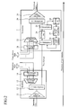
- FIG. 2 depicts a configuration of a wavelength-division multiplexing transmission device according to Embodiment 1 of the present invention.
- the wavelength-division multiplexing transmission device includes a receiver 1 and a transmitter 2.
- the receiver 1 separates, per wavelength, the wavelength-division multiplexed light input from the transmission line-a, and demodulate them to generate original signals.
- the receiver 1 includes an optical amplifier 11, a 1:2 demultiplexer 12, a wavelength separator 13, and a wavelength converter 14.
- the optical amplifier 11 is adapted to amplify the wavelength-division multiplexed light input from the transmission line-a, and fulfills a function of supplementing transmission line loss.
- the wavelength-division multiplexed light amplified by this optical amplifier 11 is output to the 1:2 demultiplexer 12.
- the 1:2 demultiplexer 12 is adapted to demultiplex the wavelength-division multiplexed light amplified by the optical amplifier 11 into two parts of light. While one of the two parts of light is output to the wavelength separator 13, another one of the two parts of light is output (i.e. passed through) to the transmitter 2.
- the wavelength separator 13 is adapted to separate the wavelength-division multiplexed light input through the 1:2 demultiplexer 12 into light of wavelengths per wavelength. The light of the wavelengths separated by this wavelength separator 13 are output to the wavelength converter 14.
- the wavelength converter 14 is adapted to demodulate each of the light of the wavelengths separated by the wavelength separator 13 to generate original signals.
- the signals generated by the wavelength converter 14 are output to a signal receiver (not shown) as reception data.
- the transmitter 2 modulates a plurality of signals to light of different wavelengths, performs wavelength-division multiplexing on the modulated signals, and transmits the multiplexed signal to the transmission line-b.
- the transmitter 2 includes a wavelength converter 21, a wavelength-division multiplexer 22, a 2:1 multiplexer 23, a wavelength filter 24, a 1:2 demultiplexer 25, a monitoring unit 26, a dummy light controller 27, a dummy light source 28, a 2:1 multiplexer 29, and an optical amplifier 30.
- the wavelength converter 21 is adapted to modulate per signal the transmission data input from a signal transmitter (not shown) to generate light of wavelengths.
- the light of the wavelengths modulated by the wavelength converter 21 are output to the wavelength-division multiplexer 22.
- the wavelength-division multiplexer 22 is adapted to perform wavelength-division multiplexing on the light of a plurality of wavelengths modulated by the wavelength converter 21.
- the wavelength-division multiplexed light on which wavelength-division multiplexing has been performed by the wavelength-division multiplexer 22 is output to the 2:1 multiplexer 29.
- the 2:1 multiplexer 23 is adapted to multiplex the wavelength-division multiplexed light that has been passed through by the receiver 1 and dummy light emitted from the dummy light source 28.
- the wavelength-division multiplexed light multiplexed by the 2:1 multiplexer 23 is output to the wavelength filter 24.
- the wavelength filter 24 is adapted to block a part of the wavelength-division multiplexed light to be terminated at the station, which has been input through the 2:1 multiplexer 23.
- the wavelength filter 24 is also adapted to pass other part of the wavelength-division multiplexed light through the wavelength filter 24 itself, where the passed light is not be terminated at the station.
- the wavelength-division multiplexed light passed through by the wavelength filter 24 is output to the 1:2 demultiplexer 25.
- the 1:2 demultiplexer 25 is adapted to demultiplex the wavelength-division multiplexed light output from the wavelength filter 24 into two parts of light. A first light of the wavelength-division multiplexed light that has been demultiplexed by the 1:2 demultiplexer 25 is output to the 2:1 multiplexer 29, and a second light of the wavelength-division multiplexed light is output to the monitoring unit 26.
- the monitoring unit 26 is adapted to monitor an optical level of the wavelength-division multiplexed light input through the 1:2 demultiplexer 25 to evaluate a condition of input of the wavelength-division multiplexed light.
- the monitoring unit 26 determines that the wavelength-division multiplexed light is being input normally.
- the monitoring unit 26 determines that the wavelength-division multiplexed light is not being input normally (i.e. in a condition of input interruption).
- the result made by the monitoring unit 26 on the input condition of the wavelength-division multiplexed light is supplied to the dummy light controller 27.
- the monitoring unit 26 determines that the input of the wavelength-division multiplexed light is restored from an interrupted condition to a normal condition, and then informs the dummy light controller 27 of a result of this determination.
- the dummy light controller 27 controls the dummy light source 28 so as not to emit dummy light in a case where the result informed by the monitoring unit 26 indicates normal (i.e. the wavelength-division multiplexed light is being input normally). In a case where the informed result indicates a failure (i.e., the wavelength-division multiplexed light is in a condition of input interruption), the dummy light controller 27 controls the dummy light source 28 to emit dummy light. Furthermore, the dummy light controller 27 controls the dummy light source 28 to stop to emit the dummy light in a case where information of restoration to normality on the wavelength-division multiplexed light is informed by the monitoring unit 26.
- the dummy light source 28 is adapted to emit or quench dummy light under the control by the dummy light controller 27.
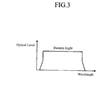
- the dummy light source 28 is configured by a light source which can fully cover the wavelengths used in the wavelength-division multiplexing transmission device (e.g. an ASE (Amplified Spontaneous Emission) light source), as depicted in FIG. 3 .
- the optical level of dummy light from the dummy light source 28 is preset to become a value approximately equal to an optical level of the wavelength-division multiplexed light passed through by the receiver 1.
- the dummy light emitted from the dummy light source 28 is output to the 2:1 multiplexer 23.
- the 2:1 multiplexer 29 is adapted to multiplex the wavelength-division multiplexed light on which wavelength-division multiplexing is performed by the wavelength-division multiplexer 22 and the wavelength-division multiplexed light that has been input through the 1:2 demultiplexer 25 from the wavelength filter 24.
- the wavelength-division multiplexed light multiplexed by the 2:1 multiplexer 29 is output to the optical amplifier 30.
- the optical amplifier 30 is adapted to amplify the wavelength-division multiplexed light multiplexed by the 2:1 multiplexer 29.
- the wavelength-division multiplexed light amplified by the optical amplifier 30 is sent into the transmission line-b.
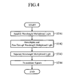
- FIG. 4 is a flowchart describing an operation of the receiver 1 in Embodiment 1 of the present invention.
- the optical amplifier 11 amplifies the wavelength-division multiplexed light input from the transmission line-a (step ST41).
- the wavelength-division multiplexed light input from the transmission line-a comprises light of a transmission wavelength which terminates at the station and light of a pass-through wavelength which does not terminate at the station (i.e. light to be passed through to a next station).
- the wavelength-division multiplexed light amplified by the optical amplifier 11 is output to the 1:2 demultiplexer 12.
- the 1:2 demultiplexer 12 demultiplexes the wavelength-division multiplexed light amplified by the optical amplifier 11 into two parts of light (step ST42). One of the two parts of light demultiplexed by the 1:2 demultiplexer 12 is output to the wavelength separator 13, and another one is output (i.e. passed through) to the transmitter 2.
- the wavelength separator 13 separates the wavelength-division multiplexed light from the 1:2 demultiplexer 12 into light of wavelengths per wavelength (step ST43). The light of the wavelengths separated by the wavelength separator 13 are output to the wavelength converter 14.
- the wavelength converter 14 demodulates the light of the wavelengths separated by the wavelength separator 13 to generate original signals (step ST44). These signals are output to a signal receiver as reception data.
- FIG. 6 is a flowchart describing the operation of the transmitter 2 for sending wavelength-division multiplexed light in Embodiment 1 of the present invention.
- the wavelength converter 21 modulates per signal the transmission data input from a signal transmitter to generate light of wavelengths (step ST61).
- the light of the wavelengths modulated by the wavelength converter 21 are output to the wavelength-division multiplexer 22.
- the wavelength-division multiplexer 22 performs wavelength-division multiplexing on the light of the wavelengths modulated by the wavelength converter 21 (step ST62).
- the wavelength-division multiplexed light generated by the wavelength-division multiplexer 22 comprises light of a transmission wavelength as depicted in FIG. 7 .
- the wavelength-division multiplexed light generated by the wavelength-division multiplexer 22 is output to the 2:1 multiplexer 29.
- the wavelength filter 24 blocks a part of the wavelength-division multiplexed light passed through by the receiver 1 via the 2:1 multiplexer 23.
- the blocked light has a wavelength to be terminated at the station.
- another part of the wavelength-division multiplexed light passed through by the receiver 1 is passed through by the wavelength filter 24 (step ST63).
- the passed through light has a wavelength which is not terminated at the station.
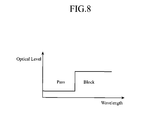
- the wavelength filter 24 has a characteristic of filter as depicted in FIG. 8 , and passes the wavelength-division multiplexed light having a pass-through wavelength, as depicted in FIG. 9 .
- the wavelength-division multiplexed light passed through and output by the wavelength filter 24 is output toward the 2:1 multiplexer 29 via the 1:2 demultiplexer 25.
- the 2:1 multiplexer 29 multiplexes the wavelength-division multiplexed light from the wavelength-division multiplexer 22 and the wavelength-division multiplexed light from the wavelength filter 24 via the 1:2 demultiplexer 25 (step ST64).
- the wavelength-division multiplexed light multiplexed by the 2:1 multiplexer 29 comprises light of a transmission wavelength and light of a pass-through wavelength.
- the wavelength-division multiplexed light multiplexed by the 2:1 multiplexer 29 is output to the optical amplifier 30.
- the optical amplifier 30 amplifies the wavelength-division multiplexed light from the 2:1 multiplexer 29 (step ST65). The amplified light is transmitted to the transmission line-b.
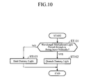
- FIG. 10 is a flowchart describing the operation of the transmitter 2 for evaluating the condition of input of wavelength-division multiplexed light in Embodiment 1 of the present invention.
- the monitoring unit 26 monitors wavelength-division multiplexed light input from the wavelength filter 24 via the 1:2 demultiplexer 25, and determines whether the wavelength-division multiplexed light is being input normally (step ST101). Specifically, in a case where the optical level being monitored agrees to a preset expected value, the monitoring unit 26 determines that the wavelength-division multiplexed light is being input normally. In a case where the optical level is less than the expected value, the monitoring unit 26 determines that the wavelength-division multiplexed light is not being input normally.
- step ST101 when the monitoring unit 26 determines that the wavelength-division multiplexed light is being input normally, the dummy light controller 27 controls the dummy light source 28 so as not to emit dummy light (step ST102).
- step ST101 when the monitoring unit 26 determines that wavelength-division multiplexed light is not being input normally (i.e. in a condition of input interruption), the dummy light controller 27 controls the dummy light source 28 to emit dummy light (step ST103).
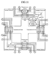
- dashed lines in FIG. 11 which depicts a case of transmitting wavelength-division multiplexed light from the terminal station A to the terminal station C
- a trouble such as disruption occurs in the transmission line-a, and interruption of input takes place on wavelength-division multiplexed light to the receiver 1 of the terminal station B.
- step ST103 by controlling the dummy light source 28 of the terminal station B to emit dummy light as depicted in FIG. 12 , dummy light as depicted in FIG. 3 is output from the 2:1 multiplexer 23. As depicted in FIG. 13 , the dummy light output from the 2:1 multiplexer 23 through the wavelength filter 24 is transformed as dummy light having wavelength components which do not terminate at the station.
- the dummy light through the 1:2 demultiplexer 25 is multiplexed with the wavelength-division multiplexed light from the wavelength-division multiplexer 22 by the 2:1 multiplexer 29.
- the multiplexed light indicates a characteristic of wavelength-division multiplexed light as depicted in FIG. 14 . Accordingly, even if an interruption of input takes place on wavelength-division multiplexed light to be passed through by the station, the output of the optical amplifier 30 of this station indicates a value approximately equal to the normal value with stability by compensating the interrupted input with dummy light. Since the dummy light does not contain signal components, a failure is detected at a later station (i.e. the terminal station C) on which a termination occurs.
- the dummy light controller 27 controls the dummy light source 28 to continue emission of dummy light. Thereafter, when the failure in the transmission line-a is resolved and a normal condition is restored from the condition of input interruption of the wavelength-division multiplexed light, the 2:1 multiplexer 23 multiplexes the dummy light and the wavelength-division multiplexed light passed through by receiver 1.
- the monitoring unit 26 Since the optical level monitored by the monitoring unit 26 becomes higher than the expected value, the monitoring unit 26 recognizes that the normal condition of the wavelength-division multiplexed light is restored. This recognition of the monitoring unit 26 is notified to the dummy light controller 27.
- the dummy light controller 27 controls the dummy light source 28 to stop to emit dummy light.
- the transmitter 2 is configured such that the optical level of the wavelength-division multiplexed light output from the wavelength filter 24 is monitored without performing regulation of the amplification rate of the optical amplifier 30, and dummy light is emitted when determining that wavelength-division multiplexed light is in a condition of input interruption. Therefore, even if a failure occurs in the transmission line-a, noise components are not amplified, and the output of the optical amplifier 30 is stabilized, which allows for maintenance of higher transmission quality.
- FIG. 15 depicts a configuration of a wavelength-division multiplexing transmission device according to Embodiment 2 of the present invention.
- a wavelength-division multiplexing transmission device according to this Embodiment 2 depicted in FIG. 15 is the wavelength-division multiplexing transmission device according to Embodiment 1 depicted in FIG. 2 in which the 1:2 demultiplexer 25 and the monitoring unit 26 are removed from the transmitter 2, and the wavelength converter 14 of the receiver 1 is changed as a wavelength converter 15.
- the other configuration is the same and like reference numerals are assigned to skip redundant description.
- FIG. 16 depicts a configuration of the wavelength converter 15 in Embodiment 2.
- the wavelength converter 15 is adapted to modulate light of wavelengths separated by the wavelength separator 13 to generate original signals.
- the wavelength converter 15 has subblocks 151 according to the number of wavelengths, each of which demodulates light of a specific wavelength to generate the original signal.
- Each of the subblocks 151 includes a 1:2 demultiplexer 152, a reception data converter 153, and a monitoring unit 154.
- the wavelength converter 15 has a supervising unit 155.
- the 1:2 demultiplexer 152 is adapted to demultiplex light of a wavelength separated by the wavelength separator 13 into two parts of light. One of the two parts of light is output to the reception data converter 153, and another one is output to the monitoring unit 154.
- the reception data converter 153 is adapted to demodulate the light of the wavelength input from the wavelength separator 13 via the 1:2 demultiplexer 152 to generate original signals.
- the signals resulting from the demodulation by the reception data converter 153 are output to a signal receiver as reception data.
- the monitoring unit 154 is adapted to monitor the optical level of the light of the wavelength input from the wavelength separator 13 via the 1:2 demultiplexer 152, and evaluates the condition of input of the monitored light.
- the monitoring unit 154 is one that has already been in use from before for evaluating the input condition of light of individual wavelengths. When the monitored optical level agrees to a preset expected value, the monitoring unit 154 determines that the light of the wavelength is being input normally. On the other hand, when the monitored optical level is less than the expected value, the monitoring unit 154 determines that the light of the wavelength is not being input normally (i.e. in a condition of input interruption). The determination made by the monitoring units 154 on the input conditions of the light of the wavelengths are informed to the supervising unit 155.
- the monitoring unit 154 determines that the light of the wavelength is restored to a normal condition from the input interruption condition, and then informs the supervising unit 155 of this situation.
- the supervising unit 155 is adapted to collect the results of determination on input conditions of the light of the wavelengths from each of the monitoring units 154, and supervises the input conditions of light of the whole wavelengths.
- the supervising result made by the supervising unit 155 on input conditions of the light of the whole wavelengths is output to the dummy light controller 27.
- the supervising unit 155 informs the dummy light controller 27 of this situation.
- the dummy light controller 27 controls the dummy light source 28 so as not to emit dummy light in accordance with the information on the result of input condition from the supervising unit 155. Meanwhile, in case where the result indicates failure (i.e. the light of the entire wavelengths are in a condition of input interruption), the dummy light source 28 is controlled to emit dummy light. Furthermore, upon receipt of information of restoration to normality of the light of the wavelengths from the supervising unit 155, the dummy light controller 27 controls the dummy light source 28 to stop emission of dummy light.
- the condition of input of the wavelength-division multiplexed light that has been demultiplexed and passed through by the 1:2 demultiplexer 12 is evaluated by using an interruption detecting function of the monitoring units 154 that have already been in use from before to monitor the light of wavelengths demultiplexed by the 1:2 demultiplexer 12 and separated by the wavelength separator 13. Accordingly, as compared with Embodiment 1, the 1:2 demultiplexer 25 and the monitoring unit 26 may be eliminated, and reduction is achieved with respect to the number of components (i.e. an additional component are not needed).
- the light of a wavelength to be passed through and the light of a wavelength resulting from modulation of transmission data are both wavelength-division multiplexed light in which light of a plurality of different wavelengths are multiplexed, however, light of a single wavelength may also be adopted as the light of a wavelength to be passed through and the light of a wavelength resulting from modulation of transmission data.
- the wavelength-division multiplexing transmission device is configured to stabilize output of the optical amplifier of the transmitter without causing amplification of noise components even in case of occurrence of failure in a transmission line and also to maintain higher transmission quality. Therefore, this invention is suitable to devices including a wavelength-division multiplexing transmission device having the pass-through function for stabilizing output light even in case of interruption in input of wavelength-division multiplexed light.
Landscapes
- Engineering & Computer Science (AREA)
- Computer Networks & Wireless Communication (AREA)
- Signal Processing (AREA)
- Optical Communication System (AREA)
Applications Claiming Priority (2)
| Application Number | Priority Date | Filing Date | Title |
|---|---|---|---|
| JP2010143915 | 2010-06-24 | ||
| PCT/JP2011/003499 WO2011161929A1 (ja) | 2010-06-24 | 2011-06-20 | 波長多重伝送装置 |
Publications (3)
| Publication Number | Publication Date |
|---|---|
| EP2587701A1 true EP2587701A1 (de) | 2013-05-01 |
| EP2587701A4 EP2587701A4 (de) | 2016-08-31 |
| EP2587701B1 EP2587701B1 (de) | 2018-10-24 |
Family
ID=45371136
Family Applications (1)
| Application Number | Title | Priority Date | Filing Date |
|---|---|---|---|
| EP11797818.9A Active EP2587701B1 (de) | 2010-06-24 | 2011-06-20 | Wellenlängen-multiplex-übertragungsvorrichtung |
Country Status (5)
| Country | Link |
|---|---|
| US (1) | US8805185B2 (de) |
| EP (1) | EP2587701B1 (de) |
| JP (1) | JP5389262B2 (de) |
| CN (1) | CN102959887B (de) |
| WO (1) | WO2011161929A1 (de) |
Families Citing this family (12)
| Publication number | Priority date | Publication date | Assignee | Title |
|---|---|---|---|---|
| US9166726B2 (en) | 2011-04-20 | 2015-10-20 | Nec Corporation | Diverging device with OADM function and wavelength division multiplexing optical network system and method therefor |
| JP5939811B2 (ja) * | 2012-01-26 | 2016-06-22 | 三菱電機株式会社 | 波長多重伝送装置 |
| JP6374140B2 (ja) * | 2012-10-15 | 2018-08-15 | Necプラットフォームズ株式会社 | 伝送システム及び中継装置 |
| US10419147B2 (en) * | 2014-09-03 | 2019-09-17 | Alcatel Lucent | Optical line loading using variable bandwidth noise |
| US10242672B2 (en) * | 2016-10-28 | 2019-03-26 | Microsoft Technology Licensing, Llc | Intelligent assistance in presentations |
| US10707958B2 (en) * | 2018-08-31 | 2020-07-07 | Adva Optical Networking Se | Method and apparatus for determining a maximum transmission capacity within an optical network |
| US10868614B2 (en) * | 2018-09-04 | 2020-12-15 | Ciena Corporation | Optical power replacement for faulted spectrum in channel holder based optical links |
| WO2020158190A1 (ja) * | 2019-01-31 | 2020-08-06 | 日本電気株式会社 | 光伝送装置、端局装置、光通信システム及び光通信方法 |
| US11664891B2 (en) * | 2019-03-04 | 2023-05-30 | Nec Corporation | Optical multiplexer/demultiplexer, optical submarine cable system, optical multiplexing/demultiplexing method, and non-transitory computer readable medium |
| US10833791B1 (en) | 2019-06-17 | 2020-11-10 | Ciena Corporation | Reducing interference from channel holders in an optical link |
| CN115244872B (zh) * | 2020-03-02 | 2024-06-04 | 日本电气株式会社 | 海底光通信系统和通信方法 |
| GB202012386D0 (en) * | 2020-08-10 | 2020-09-23 | Neptune Subsea Ip Ltd | Noise loading in an optical system |
Family Cites Families (20)
| Publication number | Priority date | Publication date | Assignee | Title |
|---|---|---|---|---|
| JPH045646A (ja) | 1990-04-23 | 1992-01-09 | Brother Ind Ltd | 画像記録装置のマスク原版 |
| JP2799230B2 (ja) | 1990-07-27 | 1998-09-17 | コニカ株式会社 | 静電荷現像用キャリア |
| JP3379052B2 (ja) | 1994-09-26 | 2003-02-17 | 富士通株式会社 | 波長多重光増幅装置及び光波長多重伝送システム及び光波長多重伝送方法 |
| US6064514A (en) | 1995-10-30 | 2000-05-16 | Nec Corporation | Optical surge preventing method and system for use with or in a rare earth doped fiber circuit |
| JPH09321373A (ja) * | 1996-05-31 | 1997-12-12 | Nec Corp | 光信号監視回路および光増幅器 |
| JP3821920B2 (ja) * | 1996-09-17 | 2006-09-13 | 富士通株式会社 | 光通信システム |
| JPH10229386A (ja) | 1997-02-17 | 1998-08-25 | Nec Corp | 光ファイバアンプとこれを用いた光通信システム |
| JP3112070B2 (ja) * | 1997-04-28 | 2000-11-27 | 日本電気株式会社 | 光ネットワークおよびそのスイッチ制御方法 |
| CN1255259A (zh) | 1998-02-06 | 2000-05-31 | 富士通株式会社 | 光放大器,用于光放器中的激励光源控制方法,和光放大器控制方法 |
| JP3551407B2 (ja) * | 1998-02-16 | 2004-08-04 | 富士通株式会社 | 波長多重光伝送システム |
| JP3605629B2 (ja) * | 1998-12-15 | 2004-12-22 | 富士通株式会社 | 光源の冗長切替方法及び該方法による波長多重伝送装置 |
| JP2002198599A (ja) * | 2000-12-22 | 2002-07-12 | Nec Corp | 光増幅器および光増幅方法 |
| JP4084144B2 (ja) | 2002-09-10 | 2008-04-30 | 富士通株式会社 | 光増幅装置 |
| JP4652723B2 (ja) | 2004-06-01 | 2011-03-16 | 三菱電機株式会社 | 光分岐挿入装置、光分岐挿入装置体、波長多重伝送システム及び波長多重伝送システムの制御方法 |
| JP4489522B2 (ja) * | 2004-07-20 | 2010-06-23 | 富士通株式会社 | 波長多重光伝送システム |
| JP4569222B2 (ja) | 2004-08-24 | 2010-10-27 | 日本電気株式会社 | 光分岐挿入装置並びに光分岐挿入方法 |
| JP5076660B2 (ja) * | 2007-06-11 | 2012-11-21 | 日本電気株式会社 | 波長多重伝送装置、制御方法及び制御プログラム |
| CN100574246C (zh) * | 2007-08-09 | 2009-12-23 | 上海交通大学 | 基于正交调制码型的全光虚拟专网的系统 |
| US8554081B2 (en) * | 2008-07-09 | 2013-10-08 | Tyco Electronics Subsea Communications, Llc | Optical add/drop multiplexer including reconfigurable filters and system including the same |
| CN102687428B (zh) * | 2009-10-16 | 2016-01-20 | 日本电气株式会社 | 光分路单元、光通信系统和光复用方法 |
-
2011
- 2011-06-20 WO PCT/JP2011/003499 patent/WO2011161929A1/ja not_active Ceased
- 2011-06-20 CN CN201180031066.1A patent/CN102959887B/zh not_active Expired - Fee Related
- 2011-06-20 EP EP11797818.9A patent/EP2587701B1/de active Active
- 2011-06-20 US US13/583,958 patent/US8805185B2/en not_active Expired - Fee Related
- 2011-06-20 JP JP2012521314A patent/JP5389262B2/ja not_active Expired - Fee Related
Also Published As
| Publication number | Publication date |
|---|---|
| CN102959887A (zh) | 2013-03-06 |
| EP2587701A4 (de) | 2016-08-31 |
| CN102959887B (zh) | 2015-06-17 |
| EP2587701B1 (de) | 2018-10-24 |
| WO2011161929A1 (ja) | 2011-12-29 |
| JP5389262B2 (ja) | 2014-01-15 |
| US8805185B2 (en) | 2014-08-12 |
| JPWO2011161929A1 (ja) | 2013-08-19 |
| US20130004166A1 (en) | 2013-01-03 |
Similar Documents
| Publication | Publication Date | Title |
|---|---|---|
| EP2587701B1 (de) | Wellenlängen-multiplex-übertragungsvorrichtung | |
| US7515829B2 (en) | Wavelength division multiplexing optical transmission system | |
| US7409155B2 (en) | Optical transmission system | |
| US11115128B2 (en) | Optical transmission device, transmission system, and control method for transmission system | |
| US7068931B2 (en) | Alarm control system and method | |
| US7738163B2 (en) | Optical transmission system | |
| EP1365529B1 (de) | Vorrichtung und Verfahren zur Steuerung eines Hauptsignals in einem optischen WDM Kommunikationssystem | |
| JP2012109653A (ja) | 波長多重伝送装置 | |
| JP5887698B2 (ja) | 光合分岐装置及び光合分岐方法 | |
| US11870553B2 (en) | Fiber-optic communication apparatus, fiber-optic communication system, and optical power control method | |
| JP2003218792A (ja) | 波長分割多重光伝送装置及びその装置を用いた通信システム | |
| EP3051720B1 (de) | Transportvorrichtung, transportsystem, transportverfahren und speichermedium mit einem darauf gespeicherten programm | |
| EP3611847B1 (de) | Umschaltvorrichtung für optische übertragungswege, optisches übertragungssystem und umschaltverfahren für übertragungsweg | |
| JP5627489B2 (ja) | 波長多重伝送装置 | |
| US12107625B2 (en) | Failure detection device, failure detection method, and failure-detection-program recording medium | |
| CN111164842A (zh) | 光学放大装置和光学放大方法 | |
| US20230104128A1 (en) | Submarine optical communication system and communication method | |
| EP0936759A2 (de) | Optisches Übertragungssystem, Endgerät und optischer Empfänger | |
| US20010022684A1 (en) | Optical amplifier and wavelength multiplexing optical transmission system | |
| JPH05292033A (ja) | 光伝送路の監視制御システム | |
| US7076165B2 (en) | Optical transponder with add/drop operation function of optical channels | |
| JPH11298408A (ja) | 光伝送装置、エンドタ―ミナル及び光中継器 | |
| JP5939811B2 (ja) | 波長多重伝送装置 | |
| JP5910089B2 (ja) | 波長多重光伝送システム | |
| JP2016195358A (ja) | 通信装置及び波長調整方法 |
Legal Events
| Date | Code | Title | Description |
|---|---|---|---|
| PUAI | Public reference made under article 153(3) epc to a published international application that has entered the european phase |
Free format text: ORIGINAL CODE: 0009012 |
|
| 17P | Request for examination filed |
Effective date: 20121214 |
|
| AK | Designated contracting states |
Kind code of ref document: A1 Designated state(s): AL AT BE BG CH CY CZ DE DK EE ES FI FR GB GR HR HU IE IS IT LI LT LU LV MC MK MT NL NO PL PT RO RS SE SI SK SM TR |
|
| DAX | Request for extension of the european patent (deleted) | ||
| REG | Reference to a national code |
Ref country code: DE Ref legal event code: R079 Ref document number: 602011053254 Country of ref document: DE Free format text: PREVIOUS MAIN CLASS: H04J0014000000 Ipc: H04J0014020000 |
|
| RA4 | Supplementary search report drawn up and despatched (corrected) |
Effective date: 20160803 |
|
| RIC1 | Information provided on ipc code assigned before grant |
Ipc: H04J 14/00 20060101ALI20160728BHEP Ipc: H04J 14/02 20060101AFI20160728BHEP |
|
| GRAP | Despatch of communication of intention to grant a patent |
Free format text: ORIGINAL CODE: EPIDOSNIGR1 |
|
| STAA | Information on the status of an ep patent application or granted ep patent |
Free format text: STATUS: GRANT OF PATENT IS INTENDED |
|
| INTG | Intention to grant announced |
Effective date: 20180420 |
|
| GRAS | Grant fee paid |
Free format text: ORIGINAL CODE: EPIDOSNIGR3 |
|
| GRAA | (expected) grant |
Free format text: ORIGINAL CODE: 0009210 |
|
| STAA | Information on the status of an ep patent application or granted ep patent |
Free format text: STATUS: THE PATENT HAS BEEN GRANTED |
|
| AK | Designated contracting states |
Kind code of ref document: B1 Designated state(s): AL AT BE BG CH CY CZ DE DK EE ES FI FR GB GR HR HU IE IS IT LI LT LU LV MC MK MT NL NO PL PT RO RS SE SI SK SM TR |
|
| REG | Reference to a national code |
Ref country code: GB Ref legal event code: FG4D |
|
| REG | Reference to a national code |
Ref country code: CH Ref legal event code: EP |
|
| REG | Reference to a national code |
Ref country code: IE Ref legal event code: FG4D |
|
| REG | Reference to a national code |
Ref country code: AT Ref legal event code: REF Ref document number: 1057943 Country of ref document: AT Kind code of ref document: T Effective date: 20181115 |
|
| REG | Reference to a national code |
Ref country code: DE Ref legal event code: R096 Ref document number: 602011053254 Country of ref document: DE |
|
| REG | Reference to a national code |
Ref country code: NL Ref legal event code: MP Effective date: 20181024 |
|
| REG | Reference to a national code |
Ref country code: LT Ref legal event code: MG4D |
|
| REG | Reference to a national code |
Ref country code: AT Ref legal event code: MK05 Ref document number: 1057943 Country of ref document: AT Kind code of ref document: T Effective date: 20181024 |
|
| PG25 | Lapsed in a contracting state [announced via postgrant information from national office to epo] |
Ref country code: NL Free format text: LAPSE BECAUSE OF FAILURE TO SUBMIT A TRANSLATION OF THE DESCRIPTION OR TO PAY THE FEE WITHIN THE PRESCRIBED TIME-LIMIT Effective date: 20181024 |
|
| PG25 | Lapsed in a contracting state [announced via postgrant information from national office to epo] |
Ref country code: ES Free format text: LAPSE BECAUSE OF FAILURE TO SUBMIT A TRANSLATION OF THE DESCRIPTION OR TO PAY THE FEE WITHIN THE PRESCRIBED TIME-LIMIT Effective date: 20181024 Ref country code: LV Free format text: LAPSE BECAUSE OF FAILURE TO SUBMIT A TRANSLATION OF THE DESCRIPTION OR TO PAY THE FEE WITHIN THE PRESCRIBED TIME-LIMIT Effective date: 20181024 Ref country code: AT Free format text: LAPSE BECAUSE OF FAILURE TO SUBMIT A TRANSLATION OF THE DESCRIPTION OR TO PAY THE FEE WITHIN THE PRESCRIBED TIME-LIMIT Effective date: 20181024 Ref country code: IS Free format text: LAPSE BECAUSE OF FAILURE TO SUBMIT A TRANSLATION OF THE DESCRIPTION OR TO PAY THE FEE WITHIN THE PRESCRIBED TIME-LIMIT Effective date: 20190224 Ref country code: FI Free format text: LAPSE BECAUSE OF FAILURE TO SUBMIT A TRANSLATION OF THE DESCRIPTION OR TO PAY THE FEE WITHIN THE PRESCRIBED TIME-LIMIT Effective date: 20181024 Ref country code: NO Free format text: LAPSE BECAUSE OF FAILURE TO SUBMIT A TRANSLATION OF THE DESCRIPTION OR TO PAY THE FEE WITHIN THE PRESCRIBED TIME-LIMIT Effective date: 20190124 Ref country code: HR Free format text: LAPSE BECAUSE OF FAILURE TO SUBMIT A TRANSLATION OF THE DESCRIPTION OR TO PAY THE FEE WITHIN THE PRESCRIBED TIME-LIMIT Effective date: 20181024 Ref country code: PL Free format text: LAPSE BECAUSE OF FAILURE TO SUBMIT A TRANSLATION OF THE DESCRIPTION OR TO PAY THE FEE WITHIN THE PRESCRIBED TIME-LIMIT Effective date: 20181024 Ref country code: LT Free format text: LAPSE BECAUSE OF FAILURE TO SUBMIT A TRANSLATION OF THE DESCRIPTION OR TO PAY THE FEE WITHIN THE PRESCRIBED TIME-LIMIT Effective date: 20181024 Ref country code: BG Free format text: LAPSE BECAUSE OF FAILURE TO SUBMIT A TRANSLATION OF THE DESCRIPTION OR TO PAY THE FEE WITHIN THE PRESCRIBED TIME-LIMIT Effective date: 20190124 |
|
| PG25 | Lapsed in a contracting state [announced via postgrant information from national office to epo] |
Ref country code: RS Free format text: LAPSE BECAUSE OF FAILURE TO SUBMIT A TRANSLATION OF THE DESCRIPTION OR TO PAY THE FEE WITHIN THE PRESCRIBED TIME-LIMIT Effective date: 20181024 Ref country code: GR Free format text: LAPSE BECAUSE OF FAILURE TO SUBMIT A TRANSLATION OF THE DESCRIPTION OR TO PAY THE FEE WITHIN THE PRESCRIBED TIME-LIMIT Effective date: 20190125 Ref country code: SE Free format text: LAPSE BECAUSE OF FAILURE TO SUBMIT A TRANSLATION OF THE DESCRIPTION OR TO PAY THE FEE WITHIN THE PRESCRIBED TIME-LIMIT Effective date: 20181024 Ref country code: AL Free format text: LAPSE BECAUSE OF FAILURE TO SUBMIT A TRANSLATION OF THE DESCRIPTION OR TO PAY THE FEE WITHIN THE PRESCRIBED TIME-LIMIT Effective date: 20181024 Ref country code: PT Free format text: LAPSE BECAUSE OF FAILURE TO SUBMIT A TRANSLATION OF THE DESCRIPTION OR TO PAY THE FEE WITHIN THE PRESCRIBED TIME-LIMIT Effective date: 20190224 |
|
| REG | Reference to a national code |
Ref country code: DE Ref legal event code: R097 Ref document number: 602011053254 Country of ref document: DE |
|
| PG25 | Lapsed in a contracting state [announced via postgrant information from national office to epo] |
Ref country code: CZ Free format text: LAPSE BECAUSE OF FAILURE TO SUBMIT A TRANSLATION OF THE DESCRIPTION OR TO PAY THE FEE WITHIN THE PRESCRIBED TIME-LIMIT Effective date: 20181024 Ref country code: DK Free format text: LAPSE BECAUSE OF FAILURE TO SUBMIT A TRANSLATION OF THE DESCRIPTION OR TO PAY THE FEE WITHIN THE PRESCRIBED TIME-LIMIT Effective date: 20181024 Ref country code: IT Free format text: LAPSE BECAUSE OF FAILURE TO SUBMIT A TRANSLATION OF THE DESCRIPTION OR TO PAY THE FEE WITHIN THE PRESCRIBED TIME-LIMIT Effective date: 20181024 |
|
| PG25 | Lapsed in a contracting state [announced via postgrant information from national office to epo] |
Ref country code: RO Free format text: LAPSE BECAUSE OF FAILURE TO SUBMIT A TRANSLATION OF THE DESCRIPTION OR TO PAY THE FEE WITHIN THE PRESCRIBED TIME-LIMIT Effective date: 20181024 Ref country code: SK Free format text: LAPSE BECAUSE OF FAILURE TO SUBMIT A TRANSLATION OF THE DESCRIPTION OR TO PAY THE FEE WITHIN THE PRESCRIBED TIME-LIMIT Effective date: 20181024 Ref country code: SM Free format text: LAPSE BECAUSE OF FAILURE TO SUBMIT A TRANSLATION OF THE DESCRIPTION OR TO PAY THE FEE WITHIN THE PRESCRIBED TIME-LIMIT Effective date: 20181024 Ref country code: EE Free format text: LAPSE BECAUSE OF FAILURE TO SUBMIT A TRANSLATION OF THE DESCRIPTION OR TO PAY THE FEE WITHIN THE PRESCRIBED TIME-LIMIT Effective date: 20181024 |
|
| PLBE | No opposition filed within time limit |
Free format text: ORIGINAL CODE: 0009261 |
|
| STAA | Information on the status of an ep patent application or granted ep patent |
Free format text: STATUS: NO OPPOSITION FILED WITHIN TIME LIMIT |
|
| 26N | No opposition filed |
Effective date: 20190725 |
|
| PG25 | Lapsed in a contracting state [announced via postgrant information from national office to epo] |
Ref country code: SI Free format text: LAPSE BECAUSE OF FAILURE TO SUBMIT A TRANSLATION OF THE DESCRIPTION OR TO PAY THE FEE WITHIN THE PRESCRIBED TIME-LIMIT Effective date: 20181024 |
|
| PG25 | Lapsed in a contracting state [announced via postgrant information from national office to epo] |
Ref country code: MC Free format text: LAPSE BECAUSE OF FAILURE TO SUBMIT A TRANSLATION OF THE DESCRIPTION OR TO PAY THE FEE WITHIN THE PRESCRIBED TIME-LIMIT Effective date: 20181024 |
|
| REG | Reference to a national code |
Ref country code: CH Ref legal event code: PL |
|
| REG | Reference to a national code |
Ref country code: BE Ref legal event code: MM Effective date: 20190630 |
|
| PG25 | Lapsed in a contracting state [announced via postgrant information from national office to epo] |
Ref country code: TR Free format text: LAPSE BECAUSE OF FAILURE TO SUBMIT A TRANSLATION OF THE DESCRIPTION OR TO PAY THE FEE WITHIN THE PRESCRIBED TIME-LIMIT Effective date: 20181024 |
|
| PG25 | Lapsed in a contracting state [announced via postgrant information from national office to epo] |
Ref country code: IE Free format text: LAPSE BECAUSE OF NON-PAYMENT OF DUE FEES Effective date: 20190620 |
|
| PG25 | Lapsed in a contracting state [announced via postgrant information from national office to epo] |
Ref country code: BE Free format text: LAPSE BECAUSE OF NON-PAYMENT OF DUE FEES Effective date: 20190630 Ref country code: LU Free format text: LAPSE BECAUSE OF NON-PAYMENT OF DUE FEES Effective date: 20190620 Ref country code: LI Free format text: LAPSE BECAUSE OF NON-PAYMENT OF DUE FEES Effective date: 20190630 Ref country code: CH Free format text: LAPSE BECAUSE OF NON-PAYMENT OF DUE FEES Effective date: 20190630 |
|
| PGFP | Annual fee paid to national office [announced via postgrant information from national office to epo] |
Ref country code: DE Payment date: 20200609 Year of fee payment: 10 |
|
| PGFP | Annual fee paid to national office [announced via postgrant information from national office to epo] |
Ref country code: GB Payment date: 20200610 Year of fee payment: 10 |
|
| PG25 | Lapsed in a contracting state [announced via postgrant information from national office to epo] |
Ref country code: CY Free format text: LAPSE BECAUSE OF FAILURE TO SUBMIT A TRANSLATION OF THE DESCRIPTION OR TO PAY THE FEE WITHIN THE PRESCRIBED TIME-LIMIT Effective date: 20181024 |
|
| PG25 | Lapsed in a contracting state [announced via postgrant information from national office to epo] |
Ref country code: HU Free format text: LAPSE BECAUSE OF FAILURE TO SUBMIT A TRANSLATION OF THE DESCRIPTION OR TO PAY THE FEE WITHIN THE PRESCRIBED TIME-LIMIT; INVALID AB INITIO Effective date: 20110620 Ref country code: MT Free format text: LAPSE BECAUSE OF FAILURE TO SUBMIT A TRANSLATION OF THE DESCRIPTION OR TO PAY THE FEE WITHIN THE PRESCRIBED TIME-LIMIT Effective date: 20181024 |
|
| REG | Reference to a national code |
Ref country code: DE Ref legal event code: R119 Ref document number: 602011053254 Country of ref document: DE |
|
| GBPC | Gb: european patent ceased through non-payment of renewal fee |
Effective date: 20210620 |
|
| PG25 | Lapsed in a contracting state [announced via postgrant information from national office to epo] |
Ref country code: GB Free format text: LAPSE BECAUSE OF NON-PAYMENT OF DUE FEES Effective date: 20210620 Ref country code: DE Free format text: LAPSE BECAUSE OF NON-PAYMENT OF DUE FEES Effective date: 20220101 |
|
| PG25 | Lapsed in a contracting state [announced via postgrant information from national office to epo] |
Ref country code: MK Free format text: LAPSE BECAUSE OF FAILURE TO SUBMIT A TRANSLATION OF THE DESCRIPTION OR TO PAY THE FEE WITHIN THE PRESCRIBED TIME-LIMIT Effective date: 20181024 |
|
| P01 | Opt-out of the competence of the unified patent court (upc) registered |
Effective date: 20230512 |
|
| PGFP | Annual fee paid to national office [announced via postgrant information from national office to epo] |
Ref country code: FR Payment date: 20250508 Year of fee payment: 15 |