EP2587901A2 - Gehäuse mit einem Unterteil und einem Deckel - Google Patents
Gehäuse mit einem Unterteil und einem Deckel Download PDFInfo
- Publication number
- EP2587901A2 EP2587901A2 EP12006276.5A EP12006276A EP2587901A2 EP 2587901 A2 EP2587901 A2 EP 2587901A2 EP 12006276 A EP12006276 A EP 12006276A EP 2587901 A2 EP2587901 A2 EP 2587901A2
- Authority
- EP
- European Patent Office
- Prior art keywords
- housing
- clamping element
- fixed axis
- latched position
- housing component
- Prior art date
- Legal status (The legal status is an assumption and is not a legal conclusion. Google has not performed a legal analysis and makes no representation as to the accuracy of the status listed.)
- Granted
Links
Images


Classifications
-
- B—PERFORMING OPERATIONS; TRANSPORTING
- B65—CONVEYING; PACKING; STORING; HANDLING THIN OR FILAMENTARY MATERIAL
- B65D—CONTAINERS FOR STORAGE OR TRANSPORT OF ARTICLES OR MATERIALS, e.g. BAGS, BARRELS, BOTTLES, BOXES, CANS, CARTONS, CRATES, DRUMS, JARS, TANKS, HOPPERS, FORWARDING CONTAINERS; ACCESSORIES, CLOSURES, OR FITTINGS THEREFOR; PACKAGING ELEMENTS; PACKAGES
- B65D43/00—Lids or covers for rigid or semi-rigid containers
- B65D43/14—Non-removable lids or covers
- B65D43/16—Non-removable lids or covers hinged for upward or downward movement
- B65D43/163—Non-removable lids or covers hinged for upward or downward movement the container and the lid being made separately
- B65D43/166—Non-removable lids or covers hinged for upward or downward movement the container and the lid being made separately and connected by separate interfitting hinge elements fixed to the container and the lid respectively
- B65D43/167—Non-removable lids or covers hinged for upward or downward movement the container and the lid being made separately and connected by separate interfitting hinge elements fixed to the container and the lid respectively these elements being assembled by a separate pin-like member
-
- B—PERFORMING OPERATIONS; TRANSPORTING
- B65—CONVEYING; PACKING; STORING; HANDLING THIN OR FILAMENTARY MATERIAL
- B65D—CONTAINERS FOR STORAGE OR TRANSPORT OF ARTICLES OR MATERIALS, e.g. BAGS, BARRELS, BOTTLES, BOXES, CANS, CARTONS, CRATES, DRUMS, JARS, TANKS, HOPPERS, FORWARDING CONTAINERS; ACCESSORIES, CLOSURES, OR FITTINGS THEREFOR; PACKAGING ELEMENTS; PACKAGES
- B65D43/00—Lids or covers for rigid or semi-rigid containers
- B65D43/02—Removable lids or covers
- B65D43/0202—Removable lids or covers without integral tamper element
- B65D43/0214—Removable lids or covers without integral tamper element secured only by friction or gravity
- B65D43/0218—Removable lids or covers without integral tamper element secured only by friction or gravity on both the inside and the outside of the mouth of the container
-
- B—PERFORMING OPERATIONS; TRANSPORTING
- B65—CONVEYING; PACKING; STORING; HANDLING THIN OR FILAMENTARY MATERIAL
- B65D—CONTAINERS FOR STORAGE OR TRANSPORT OF ARTICLES OR MATERIALS, e.g. BAGS, BARRELS, BOTTLES, BOXES, CANS, CARTONS, CRATES, DRUMS, JARS, TANKS, HOPPERS, FORWARDING CONTAINERS; ACCESSORIES, CLOSURES, OR FITTINGS THEREFOR; PACKAGING ELEMENTS; PACKAGES
- B65D45/00—Clamping or other pressure-applying devices for securing or retaining closure members
- B65D45/02—Clamping or other pressure-applying devices for securing or retaining closure members for applying axial pressure to engage closure with sealing surface
- B65D45/16—Clips, hooks, or clamps which are removable, or which remain connected either with the closure or with the container when the container is open, e.g. C-shaped
- B65D45/20—Clips, hooks, or clamps which are removable, or which remain connected either with the closure or with the container when the container is open, e.g. C-shaped pivoted
-
- H—ELECTRICITY
- H05—ELECTRIC TECHNIQUES NOT OTHERWISE PROVIDED FOR
- H05K—PRINTED CIRCUITS; CASINGS OR CONSTRUCTIONAL DETAILS OF ELECTRIC APPARATUS; MANUFACTURE OF ASSEMBLAGES OF ELECTRICAL COMPONENTS
- H05K5/00—Casings, cabinets or drawers for electric apparatus
- H05K5/02—Details
- H05K5/0217—Mechanical details of casings
- H05K5/0226—Hinges
-
- H—ELECTRICITY
- H05—ELECTRIC TECHNIQUES NOT OTHERWISE PROVIDED FOR
- H05K—PRINTED CIRCUITS; CASINGS OR CONSTRUCTIONAL DETAILS OF ELECTRIC APPARATUS; MANUFACTURE OF ASSEMBLAGES OF ELECTRICAL COMPONENTS
- H05K5/00—Casings, cabinets or drawers for electric apparatus
- H05K5/10—Casings, cabinets or drawers for electric apparatus comprising several parts forming a closed casing
- H05K5/15—Casings, cabinets or drawers for electric apparatus comprising several parts forming a closed casing assembled by resilient members
-
- B—PERFORMING OPERATIONS; TRANSPORTING
- B65—CONVEYING; PACKING; STORING; HANDLING THIN OR FILAMENTARY MATERIAL
- B65D—CONTAINERS FOR STORAGE OR TRANSPORT OF ARTICLES OR MATERIALS, e.g. BAGS, BARRELS, BOTTLES, BOXES, CANS, CARTONS, CRATES, DRUMS, JARS, TANKS, HOPPERS, FORWARDING CONTAINERS; ACCESSORIES, CLOSURES, OR FITTINGS THEREFOR; PACKAGING ELEMENTS; PACKAGES
- B65D2543/00—Lids or covers essentially for box-like containers
- B65D2543/00009—Details of lids or covers for rigid or semi-rigid containers
- B65D2543/00018—Overall construction of the lid
- B65D2543/00064—Shape of the outer periphery
- B65D2543/00074—Shape of the outer periphery curved
- B65D2543/00101—Shape of the outer periphery curved square-like or rectangular-like
-
- B—PERFORMING OPERATIONS; TRANSPORTING
- B65—CONVEYING; PACKING; STORING; HANDLING THIN OR FILAMENTARY MATERIAL
- B65D—CONTAINERS FOR STORAGE OR TRANSPORT OF ARTICLES OR MATERIALS, e.g. BAGS, BARRELS, BOTTLES, BOXES, CANS, CARTONS, CRATES, DRUMS, JARS, TANKS, HOPPERS, FORWARDING CONTAINERS; ACCESSORIES, CLOSURES, OR FITTINGS THEREFOR; PACKAGING ELEMENTS; PACKAGES
- B65D2543/00—Lids or covers essentially for box-like containers
- B65D2543/00009—Details of lids or covers for rigid or semi-rigid containers
- B65D2543/00018—Overall construction of the lid
- B65D2543/00259—Materials used
- B65D2543/00296—Plastic
-
- B—PERFORMING OPERATIONS; TRANSPORTING
- B65—CONVEYING; PACKING; STORING; HANDLING THIN OR FILAMENTARY MATERIAL
- B65D—CONTAINERS FOR STORAGE OR TRANSPORT OF ARTICLES OR MATERIALS, e.g. BAGS, BARRELS, BOTTLES, BOXES, CANS, CARTONS, CRATES, DRUMS, JARS, TANKS, HOPPERS, FORWARDING CONTAINERS; ACCESSORIES, CLOSURES, OR FITTINGS THEREFOR; PACKAGING ELEMENTS; PACKAGES
- B65D2543/00—Lids or covers essentially for box-like containers
- B65D2543/00009—Details of lids or covers for rigid or semi-rigid containers
- B65D2543/00444—Contact between the container and the lid
- B65D2543/00481—Contact between the container and the lid on the inside or the outside of the container
- B65D2543/0049—Contact between the container and the lid on the inside or the outside of the container on the inside, or a part turned to the inside of the mouth of the container
- B65D2543/00518—Skirt
-
- B—PERFORMING OPERATIONS; TRANSPORTING
- B65—CONVEYING; PACKING; STORING; HANDLING THIN OR FILAMENTARY MATERIAL
- B65D—CONTAINERS FOR STORAGE OR TRANSPORT OF ARTICLES OR MATERIALS, e.g. BAGS, BARRELS, BOTTLES, BOXES, CANS, CARTONS, CRATES, DRUMS, JARS, TANKS, HOPPERS, FORWARDING CONTAINERS; ACCESSORIES, CLOSURES, OR FITTINGS THEREFOR; PACKAGING ELEMENTS; PACKAGES
- B65D2543/00—Lids or covers essentially for box-like containers
- B65D2543/00009—Details of lids or covers for rigid or semi-rigid containers
- B65D2543/00444—Contact between the container and the lid
- B65D2543/00481—Contact between the container and the lid on the inside or the outside of the container
- B65D2543/00537—Contact between the container and the lid on the inside or the outside of the container on the outside, or a part turned to the outside of the mouth of the container
-
- B—PERFORMING OPERATIONS; TRANSPORTING
- B65—CONVEYING; PACKING; STORING; HANDLING THIN OR FILAMENTARY MATERIAL
- B65D—CONTAINERS FOR STORAGE OR TRANSPORT OF ARTICLES OR MATERIALS, e.g. BAGS, BARRELS, BOTTLES, BOXES, CANS, CARTONS, CRATES, DRUMS, JARS, TANKS, HOPPERS, FORWARDING CONTAINERS; ACCESSORIES, CLOSURES, OR FITTINGS THEREFOR; PACKAGING ELEMENTS; PACKAGES
- B65D2543/00—Lids or covers essentially for box-like containers
- B65D2543/00009—Details of lids or covers for rigid or semi-rigid containers
- B65D2543/00444—Contact between the container and the lid
- B65D2543/00481—Contact between the container and the lid on the inside or the outside of the container
- B65D2543/00555—Contact between the container and the lid on the inside or the outside of the container on both the inside and the outside
Definitions
- the present invention relates to a housing having a lower part and a lid as a first and second housing member, which are interconnected via one or more clamping elements, wherein at least one clamping element is either completely detachable or usable as a hinge between the first and second housing component.
- a generic case is from the Scriptures DE 44 05 947 C1 known.
- a tensioning clamp is disclosed as a tensioning element with a joint attached to one end of the tensioning clamp.
- the clamp it is possible to completely disengage the connection of the lid with the base by removing the clamp, or leaving the clamp in the installed position on one side of the housing so that the lid is hinged to the base.
- the clamp itself is composed of several parts and therefore expensive to manufacture.
- the object is achieved for a generic housing by supporting surfaces are formed on the first housing member, with which the first housing member is supported in a latched position of the clamping element on a fixed to the second housing component fixed axis, the clamping element in its latched position on a first side the fixed axis is connected by means of a fixed axis partially embracing tab, the clamping element is locked in its latched position on a second side form-fitting manner with the first housing component and thereby holds the first housing member pressed with the support surfaces on the fixed axis, wherein the clamping element so is shaped so that it in the relaxed state with the distance between the fixed axis partially encompassing tab and the positive locking connection forming latching lug the distance between the first housing component trained locking edge of the positive locking connection to the surface facing away from the locking edge surface of the fixed axis just below and the material of the clamping element has such elasticity that it expands so far under the action of a fixed finger pressure, the distance that the latch over the locking edge of time and engages
- the object is achieved in an alternative embodiment by supporting surfaces are formed on the first housing component, with which the first housing component is supported in a latched position of the clamping element on a stationary axis formed on the second housing component, the clamping element in its latched position on a first side the fixed axis is connected by means of a fixed axis partially embracing tab, on the first housing part a locking edge is formed, which is engaged behind in a latched position of the clamping element of a clamping element on a second side locking lug and thereby the first housing component with the support surfaces holding the fixed axle pressed, the tensioning member being subjected to tensile stress in the latched position.
- the clamping element is simplified in its construction insofar as the known from the prior art clamping clip with the multi-part joint is replaced by a single molded part, which firmly connects the lid with the lower part due to its special configuration in the locked position, but by its elasticity can be solved by a simple finger pressure or as an alternative embodiment only by a tool from the locked position and so the lid is removable again, the clamping element in its latched position but also allows a hinge-like pivoting of the lid when the lid on the other pages of the housing is not connected to the lower part.
- the clamping element according to the invention is inexpensive to produce and easy to handle during assembly of the housing.
- the housing assembly is simplified and accelerated by the one-piece clamping element.
- the cost of materials for the clamping element itself also decreases, so that the housing of the invention is more cost-effective overall.
- the housing can be manufactured in a single grade in a single plastic, which brings advantages in the subsequent disposal.
- the clamping element is exposed in the latched position of a tensile stress, the lid and the lower part remain firmly held together, without that one component can move relative to the other component.
- the tensile stress is created by the distance dimension of the clamping element in its relaxed state between the fixed axis partially encompassing tab and the positive locking connection forming detent the distance between the formed on the first housing member locking edge of the positive locking connection to the surface away from the locking edge away from the fixed Axle just below the clamping element and therefore slightly expanded and elastically deformed in the latched position in relation to its shape in a relaxed state and the restoring forces that builds up the clamping element by the deformation act as tensile stress on the housing components.
- the tensile stress avoids rattling noises that can occur during a movement of the housing due to a play between the components. If the separation points between the cover and the lower part are provided with a seal, the housing is at least sufficiently tight against splashing water, Dirt and dust. Due to the fixed connection of the lid with the lower part, the case makes an overall very stable and valuable impression.
- the clamping element is designed as a pivotable about the fixed axis cover strip which extends over more than half the side length of the housing side to which it is attached, the cover strip covers the edge of the housing in a range of the second housing component trained fixed axis to the locking edge of the first housing component and under the cover strip are on the first and / or second housing component screwing, stiffening ribs, bearing surfaces, grooves, springs and / or Abdecknasen formed.
- the visually troubled elements of the connection technology in the locked position can be covered by the clamping element, the clamping element thus assumes in addition to its fixation function in addition also a design function, as far as it succeeds to hide optically under the cover strip housing technology.
- the clamping element is designed as a clip-like profile with a closed outwardly facing surface which engages over an edge region of the housing between the fixed axis and the latching edge.
- the closed and preferably smooth executed outwardly facing surface results in an attractive appearance of the entire housing.
- the uneven surfaces of the connection technique are hidden beneath the surface and are not visible in the latched position of the tension member.
- the overall impression strongly influencing edge portion of the housing can be provided with smooth surfaces and a matching housing design to the edge formation, for example, with a sharp or rounded edge and flat legs whose position is adapted to the adjacent surfaces of the housing components.
- At least two spaced-apart fixed axes are arranged on the second housing component on the side on which the clamping element is arranged. Due to the arrangement of at least two spaced-apart fixed axes, the tensile stress can be distributed over the side wall of the housing component wider and introduced into this.
- the fixed axis or axes and the positive locking connection extends only over part of the side length of the clamping element. Due to the fact that the fixed or fixed axles do not extend over the full side length of the tensioning element, sufficient space remains in the tensioning element and / or the adjacent housing components in order to be able to form stiffening ribs, screwed areas, bearing surfaces, grooves and springs and the like. Even over fixed axes, which extend only over part of the side length of the clamping element, considerable and sufficient tensile stresses can already be built up with which the cover is held on the lower part of the housing.
- the support surfaces over which the first housing member is supported on the fixed axis formed on stiffening ribs, which have on its side facing the clamping element bearing surfaces which rest in the latched position of the clamping element on the inner surfaces of the clamping element.
- the stiffening ribs can be made comparatively narrow, since they can transmit considerable support forces even with a material thickness of a solid stiffening rib of, for example, 1 mm.
- the supporting forces add up to values that exceed the loads applied during normal use.
- the formation of stiffening ribs material can be saved, and the space in which no stiffening ribs are present, can be used for other functional elements.
- stiffening ribs are formed on the clamping element, which have bearing surfaces on their side facing the first and / or the second housing component, which abut surfaces of the first and / or second housing component in the latched position of the clamping element. Due to the stiffening ribs, the clamping element is supported in its installed position and stabilized in its shape. Due to the stiffening ribs, the clamping element in its installed position in the latched position receives a high degree of rigidity, by means of which the housing as a whole makes a very good quality impression. In addition, the forces acting on the clamping element and the housing components are distributed more uniformly over the component length and width via the stiffening ribs.
- the clamping element Since the clamping element is exposed to a tensile stress in the latched position, the material of the clamping element could deform in the long term, especially in polymeric materials. In this case, the tension could subside, which could adversely affect the connection of the lower part with the lid. By supporting so the tension can be maintained in the long term.
- the first and second housing component in their abutting region on a tongue and groove connection.
- a tongue and groove connection By a tongue and groove connection, a good seal of the interior of the housing can be achieved to the outside.
- a flexible seal can be inserted into the groove / spring connection, which increases the tightness of the housing.
- the complete housing is formed only from the lid, the lower part and one or two integrally designed clamping elements. With only three or four components forming the complete housing, stockpiling, logistics and assembly are simplified. This also makes the overall housing very inexpensive to produce.
- a housing 2 is shown in a cross-sectional view.
- the housing 2 is composed of the lower part 4, on which the lid 6 is placed.
- the lower part 4 and the cover 6 are each a first and second housing component.
- the housing components can be connected to one another via the clamping elements 8. While in Fig. 1 the right clamping element 8 is shown in a latched position, the left clamping element 8 is shown in an open position.
- the clamping elements 8 have a tab 12 which surround a fixed axis 10 which is fixedly connected to the lower part 4. The tab 12 can be deducted in a pivoting position of the clamping element 8 of the fixed axis 10 when the clamping element 8 is to be completely removed from the corresponding housing member 4, 6.
- support surfaces 14 are formed, with which the lid 6 is supported on the respective fixed axis 10.
- the support surface 14 is formed on a stiffening rib 16.
- the support surface 14 may also be formed in other ways on a surface portion on the underside of the lid 6.
- the support surface 14 is free of play on the adjacent surface of the fixed axis 10. Since the support surface 14 of the peripheral contour the fixed axis 10 is adjusted, results in the embodiment in the region of the support surface 14 an uneven surface contact of the support surfaces 14 on the axis 10 as a connection between the lid 6 and the lower part 4. In a hinge-like pivotal movement of the lid 6 about the fixed axis 10th The support surfaces 14 slide over the surface of the fixed axis 10.
- a circumferential groove 18 is present on the cover 6, into which in the closed position of the cover 6, the spring 20, which is formed on the lower part 4, immersed. Due to the tongue and groove connection between the lower part 4 and the cover 6, the interior of the housing 2 is sealingly closed. In order to increase the seal in addition, in the groove 18 may be inserted a separate seal.
- a locking edge 26 is formed in the region of the clamping elements 8, which is engaged behind by a formed on the clamping element 8 locking lug 24 in the latched position of the clamping element 8.
- the locking lug 24 and the locking edge 26 form in this way a latching connection of the clamping element 8 with the lid. 6
- Fig. 2 the housing 2 is shown with a partially pivoted cover 6.
- the lid has been pivoted to the right fixed axis 10 as a hinge axis.
- the distance measure 28 between the fixed axis 10 partially encompassing tab 12 and the latch 24 of the left in Fig. 2 shown clamping element 8 is smaller than the distance 30 between the formed on the lid 6 locking edge 26 up to the side facing away from the locking edge 26 surface of the fixed axis 10 at the right in Fig. 2 shown clamping element 8.
- the clamping element 8 To the right in the housing part of the Fig. 2 To be able to assume the latched position shown, the clamping element 8 must therefore widen in its distance measure 28 to the distance measure 30.
- the tensioning element 8 builds up restoring forces due to the elasticity of the material used, as a result of which a tensile stress builds up between the lug 12 and the latching lug 24.
- tensile stress of the lid 6 is pressed with the support surfaces 14 on the fixed axis 10.
- the cover 6 is held by the clamping element 8 via the support surfaces 14 on the fixed axis 10 pivotally.
- the inner surface of the tab 12 forms, together with the support surfaces 14, a pivot bearing on the fixed axle 10, about which the cover 6 is pivotable.
- the fixed axis on the lower part 4 and the locking edge 26 is arranged on the cover 6, but the arrangement can also be reversed, in which case the tab of the clamping element 8, the fixed axis on the cover 6 and the locking lug 24, the locking lug on the lower part 4 surrounds ,
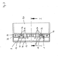
- Fig. 3 is a part of the housing 2 with the lid 6 shown from a top view.
- the clamping element 8 is in a swung-open position. From the top view, it can be seen that in the region of the lid edge 22, screw-on regions 32, bearing surfaces 34 and stiffening ribs 16 are located.
- Applied section line II corresponds substantially to a part of the sectional views according to Fig. 1 and Fig. 2 , Will that be in Fig. 3 Spheres shown 8 spent from the open pivot position in a locked position, the cover strip 36 of the clamping element 8 covers the Verschraubungs Suitee 32, the support surfaces 34 and the stiffening ribs 16.
- the am Clamping element 8 formed stiffening ribs 16 are no longer visible in the latched position of the clamping element 8.
- the clamping element 8 extends over the entire side length of the housing side, on which the clamping element is mounted. Through this length, it is possible to accommodate many functional elements such as screwed areas 32, bearing surfaces 34 and the like in the area of the lid edge 22 and to hide them in the latched position of the tensioning element 8 under the cover strip 36. In order to achieve a good force distribution between the lower part 4, the lid 6 and the clamping element 8, it is advantageous if the clamping element 8 extends over more than half the side length of the housing side, to which it is attached.
- two fixed axes 10 can be seen, which are partially encompassed by the associated tabs 12 of the clamping element 8.
- the fixed axes 10 are formed only in a partial section of the side wall of the lower part 4.
- support surfaces 14 are formed on the stiffening ribs 16. From the top view it can be seen that in the exemplary embodiment a total of six support surfaces 14 are formed on the cover side, via which the cover 6 is held in a suitably aligned position relative to the lower part 4. Also on the stiffening ribs 16, which are formed on the underside of the clamping element 8, corresponding support surfaces 14 may be formed.
- the clamping element 8 is in a latched position, the inner surface of the cover strip 36 rests on the bearing surfaces 34. In this way, the clamping element 8 and the cover strip 36 is well supported in the latched position.
- Corresponding bearing surfaces can also be formed on the inner surface of the clamping element 8 or on the stiffening ribs 16 formed on the clamping element 8.
Landscapes
- Engineering & Computer Science (AREA)
- Mechanical Engineering (AREA)
- Microelectronics & Electronic Packaging (AREA)
- Clamps And Clips (AREA)
- Pivots And Pivotal Connections (AREA)
- Casings For Electric Apparatus (AREA)
Abstract
Description
- Die vorliegende Erfindung bezieht sich auf ein Gehäuse mit einem Unterteil und einem Deckel als einem ersten und zweiten Gehäusebauteil, die über ein oder mehrere Spannelemente miteinander verbunden sind, wobei zumindest ein Spannelement wahlweise vollständig lösbar oder als Scharnier zwischen dem ersten und zweiten Gehäusebauteil nutzbar ist.
- Ein gattungsgemäßes Gehäuse ist aus der Schrift
DE 44 05 947 C1 bekannt. Dort ist eine Spannklammer als Spannelement mit einem an einem Ende der Spannklammer angebrachten Gelenk offenbart. Durch die Spannklammer ist es möglich, die Verbindung des Deckels mit dem Unterteil vollständig zu lösen, indem die Spannklammer entfernt wird, oder auf einer Seite des Gehäuses die Spannklammer in der Einbauposition zu belassen, so dass der Deckel zum Unterteil scharnierartig beweglich ist. Die Spannklammer selbst ist jedoch aus mehreren Teilen zusammengesetzt und deshalb aufwendig in der Herstellung. - Es ist die Aufgabe der vorliegenden Erfindung, das gattungsgemäße Gehäuse zu verbessern, indem das Spannelement wesentlich einfacher gestaltet wird.
- Die Aufgabe wird für ein gattungsgemäßes Gehäuse gelöst, indem am ersten Gehäusebauteil Stützflächen ausgebildet sind, mit denen sich das erste Gehäusebauteil in einer verrasteten Position des Spannelements auf einer am zweiten Gehäusebauteil ausgebildeten feststehenden Achse abstützt, das Spannelement in seiner verrasteten Position an einer ersten Seite mit der feststehenden Achse mittels einer die feststehende Achse teilweise umgreifenden Lasche verbunden ist, das Spannelement in seiner verrasteten Position auf einer zweiten Seite formschlüssig mit dem ersten Gehäusebauteil verrastet ist und dadurch das erste Gehäusebauteil mit den Stützflächen auf die feststehende Achse gedrückt hält, wobei das Spannelement so geformt ist, dass es in entspanntem Zustand mit dem Abstandsmaß zwischen der die feststehende Achse teilweise umgreifenden Lasche und der die formschlüssige Rastverbindung bildenden Rastnase das Abstandsmaß zwischen der am ersten Gehäusebauteil ausgebildeten Rastkante der formschlüssigen Rastverbindung bis zur von der Rastkante weg weisenden Oberfläche der feststehenden Achse knapp unterschreitet und das Material des Spannelements eine solche Elastizität aufweist, dass es unter Einwirkung eines festen Fingerdrucks das Abstandsmaß so weit aufweitet, dass die Rastnase über die Rastkante hinweg einrastet und seine verrastete Position einnimmt, wobei das Spannelement in der verrasteten Position einer Zugspannung ausgesetzt ist.
- Die Aufgabe wird in einer alternativen Ausgestaltung gelöst, indem am ersten Gehäusebauteil Stützflächen ausgebildet sind, mit denen sich das erste Gehäusebauteil in einer verrasteten Position des Spannelementes auf einer am zweiten Gehäusebauteil ausgebildeten feststehenden Achse abstützt, das Spannelement in seiner verrasteten Position an einer ersten Seite mit der feststehenden Achse mittels einer die feststehende Achse teilweise umgreifenden Lasche verbunden ist, am ersten Gehäusebauteil eine Rastkante eingeformt ist, die in einer verrasteten Position des Spannelements von einer am Spannelement auf einer zweiten Seite eingeformten Rastnase hintergriffen ist und dadurch das erste Gehäusebauteil mit den Stützflächen auf die feststehende Achse gedrückt hält, wobei das Spannelement in der verrasteten Position einer Zugspannung ausgesetzt ist.
- Das Spannelement wird in seiner Konstruktion insoweit vereinfacht, als die aus dem Stand der Technik bekannte Spannklammer mit dem mehrteiligen Gelenk ersetzt wird durch ein einziges Formteil, das aufgrund seiner besonderen Ausgestaltung in der verrasteten Position den Deckel mit dem Unterteil fest verbindet, durch seine Elastizität aber durch einen einfachen Fingerdruck oder als alternative Ausgestaltung nur durch ein Werkzeug aus der verrasteten Position gelöst werden kann und so der Deckel wieder abnehmbar ist, wobei das Spannelement in seiner verrasteten Position aber auch eine scharnierartige Verschwenkung des Deckels ermöglicht, wenn der Deckel auf den übrigen Seiten des Gehäuses nicht mit dem Unterteil verbunden ist.
- Das erfindungsgemäße Spannelement ist kostengünstig herstellbar und bei der Montage des Gehäuses leicht handhabbar. Die Gehäusemontage wird durch das einteilige Spannelement vereinfacht und beschleunigt.
- Der Materialaufwand für das Spannelement selbst sinkt ebenfalls, so dass das erfindungsgemäße Gehäuse insgesamt kostengünstiger ist. Das Gehäuse kann sortenrein in einem einzigen Kunststoff hergestellt werden, was Vorteile bei der späteren Entsorgung bringt.
- Zudem kann das komplette Gehäuse aus nur 4 Teilen - dem Unterteil, dem Deckel und dem Verschluss durch zwei an gegenüberliegenden Stellen angebrachten Spannelementen - fest verschlossen hergestellt werden. Dadurch wird auch die Teiledisposition und -logistik in der Fertigung vereinfacht.
- Dadurch, dass das Spannelement in der verrasteten Position einer Zugspannung ausgesetzt ist, bleiben der Deckel und das Unterteil fest aufeinander gehalten, ohne dass sich das eine Bauteil relativ zum anderen Bauteil bewegen kann. Die Zugspannung entsteht, indem das Abstandsmaß des Spannelements in seinem entspannten Zustand zwischen der die feststehende Achse teilweise umgreifenden Lasche und der die formschlüssige Rastverbindung bildenden Rastnase das Abstandsmaß zwischen der am ersten Gehäusebauteil ausgebildeten Rastkante der formschlüssigen Rastverbindung bis zur von der Rastkante weg weisenden Oberfläche der feststehenden Achse knapp unterschreitet und das Spannelement deshalb in der verrasteten Position im Verhältnis zu seiner Form in einem entspannten Zustand leicht aufgeweitet und elastisch verformt ist und die Rückstellkräfte, die das Spannelement durch die Verformung aufbaut, als Zugspannung auf die Gehäusebauteile einwirken. Durch die Zugspannung werden Klappergeräusche vermieden, die bei einer Bewegung des Gehäuses durch ein Spiel zwischen den Bauteilen auftreten können. Wenn die Trennstellen zwischen dem Deckel und dem Unterteil mit einer Dichtung versehen sind, ist das Gehäuse zumindest ausreichend dicht gegen Spritzwasser, Schmutz und Staub. Durch die feste Verbindung des Deckels mit dem Unterteil macht das Gehäuse einen insgesamt sehr stabilen und wertigen Eindruck.
- Nach einer Ausgestaltung der Erfindung ist das Spannelement als eine um die feststehende Achse verschwenkbare Abdeckleiste ausgebildet, die sich über mehr als die Hälfte der Seitenlänge der Gehäuseseite erstreckt, an der sie angebracht ist, die Abdeckleiste überdeckt den Gehäuserand in einem Bereich von der am zweiten Gehäusebauteil ausgebildeten feststehenden Achse bis zur Rastkante des ersten Gehäusebauteils und unter der Abdeckleiste sind am ersten und/oder zweiten Gehäusebauteil Verschraubungsbereiche, Versteifungsrippen, Auflageflächen, Nuten, Federn und/oder Abdecknasen ausgebildet. Durch die Ausbildung als Abdeckleiste können die optisch unruhigen Elemente der Verbindungstechnik in der verrasteten Position vom Spannelement verdeckt werden, das Spannelement übernimmt somit neben seiner Fixierungsfunktion zusätzlich auch eine Designfunktion, soweit es gelingt, unter der Abdeckleiste Gehäusetechnik optisch zu verstecken.
- Nach einer Ausgestaltung der Erfindung ist das Spannelement als ein klammerartiges Profil mit einer geschlossenen nach außen weisenden Oberfläche ausgebildet, das einen Kantenbereich des Gehäuses zwischen der feststehenden Achse und der Rastkante übergreift. Durch die geschlossene und vorzugsweise glatt ausgeführte nach außen weisende Oberfläche ergibt sich eine ansprechende Optik des gesamten Gehäuses. Die unebenen Oberflächen der Verbindungstechnik werden unter der Oberfläche verborgen und sind in der verrasteten Position des Spannelements nicht sichtbar. Gerade der optisch den Gesamteindruck stark beeinflussende Kantenbereich des Gehäuses kann dadurch mit glatten Oberflächen und einer zum übrigen Gehäusedesign passenden Kantenausbildung versehen sein, beispielsweise mit einer scharfen oder verrundeten Kante und flachen Schenkeln, deren Lage an die angrenzenden Oberflächen der Gehäusebauteile angepasst ist.
- Nach einer Ausgestaltung der Erfindung sind am zweiten Gehäusebauteil auf der Seite, auf der das Spannelement angeordnet ist, zumindest zwei beabstandet zueinander angeordnete feststehende Achsen angeordnet. Durch die Anordnung von zumindest zwei beabstandet zueinander angeordneten feststehenden Achsen kann die Zugspannung breiter über die Seitenwandung des Gehäusebauteils verteilt und in diese eingeleitet werden.
- Nach einer Ausgestaltung der Erfindung erstreckt sich die feststehende Achse oder Achsen und die formschlüssige Rastverbindung nur über einen Teil der Seitenlänge des Spannelements. Dadurch, dass sich die feststehende oder feststehenden Achsen nicht über die volle Seitenlänge des Spannelements erstrecken, bleiben im Spannelement und/oder den benachbarten Gehäusebauteilen noch ausreichend Platz übrig, um dort Versteifungsrippen, Verschraubungsbereiche, Auflageflächen, Nuten und Federn und dergleichen ausbilden zu können. Auch über feststehende Achsen, die sich nur über einen Teil der Seitenlänge des Spannelements erstrecken, können bereits erhebliche und ausreichende Zugspannungen aufgebaut werden, mit denen der Deckel auf dem Unterteil des Gehäuses gehalten ist.
- Nach einer Ausgestaltung der Erfindung sind die Stützflächen, über die sich das erste Gehäusebauteil auf der feststehenden Achse abstützt, an Versteifungsrippen ausgebildet, die auf ihrer dem Spannelement zugewandten Seite Auflageflächen aufweisen, die in der verrasteten Position des Spannelements an Innenoberflächen des Spannelements anliegen. Die Versteifungsrippen können vergleichsweise schmal ausgebildet werden, da sie schon bei einer Materialdicke einer massiven Versteifungsrippe von beispielsweise 1 mm erhebliche Stützkräfte übertragen können. Bei der Verwendung mehrerer Versteifungsrippen addieren sich die Stützkräfte zu Werten auf, die die beim üblichen Gebrauch einwirkenden Belastungen übersteigen. Durch die Ausbildung von Versteifungsrippen kann Material eingespart werden, und der Bauraum, in dem keine Versteifungsrippen vorhanden sind, kann für andere Funktionselemente genutzt werden.
- Nach einer Ausgestaltung der Erfindung sind an dem Spannelement Versteifungsrippen ausgebildet, die auf ihrer dem ersten und/oder dem zweiten Gehäusebauteil zugewandten Seite Auflageflächen aufweisen, die in der verrasteten Position des Spannelements an Oberflächen des ersten und/oder zweiten Gehäusebauteils anliegen. Durch die Versteifungsrippen wird das Spannelement in seiner Einbaulage abgestützt und in seiner Form stabilisiert. Durch die Versteifungsrippen erhält das Spannelement in seiner Einbaulage in der verrasteten Position eine hohe Steifigkeit, durch die das Gehäuse insgesamt einen sehr guten Qualitätseindruck macht. Zudem werden über die Versteifungsrippen die auf das Spannelement und die Gehäusebauteile einwirkenden Kräfte gleichmäßiger über die Bauteillänge und -breite verteilt. Da das Spannelement in der verrasteten Position einer Zugspannung ausgesetzt ist, könnte sich das Material des Spannelements auf Dauer gesehen verformen, insbesondere bei polymeren Werkstoffen. Dabei könnte die Zugspannung nachlassen, was sich nachteilig auf die Verbindung des Unterteils mit dem Deckel auswirken könnte. Durch die Abstützung kann also auf Dauer die Zugspannung erhalten bleiben.
- Nach einer Ausgestaltung der Erfindung weisen das erste und zweite Gehäusebauteil in ihrem Anstoßbereich eine Nut-/ Federverbindung auf. Durch eine Nut-/ Federverbindung kann eine gute Abdichtung des Innenraums des Gehäuses nach außen erzielt werden. Um die Dichtigkeit zu steigern, kann in die Nut-/ Federverbindung zusätzlich noch eine flexible Dichtung eingelegt sein, durch die sich die Dichtigkeit des Gehäuses erhöht.
- Nach einer Ausgestaltung der Erfindung ist das komplette Gehäuse nur aus dem Deckel, dem Unterteil und einem oder zwei einteilig ausgestalteten Spannelementen gebildet. Durch die nur drei oder vier Bauteile, die das komplette Gehäuse bilden, wird die Vorratshaltung, Logistik und die Montage vereinfacht. Auch hierdurch ist das Gehäuse insgesamt sehr kostengünstig herstellbar.
- Es wird ausdrücklich darauf hingewiesen, dass die Merkmale der vorstehend erläuterten Ausgestaltungen der Erfindung jeweils für sich und in Kombination mit den Merkmalen der anderen beschriebenen Ausgestaltungen mit dem Gegenstand des Hauptanspruches kombinierbar sind, soweit dies nicht durch technische Zwänge ausgeschlossen ist.
- Weitere Abwandlungen und Ausgestaltungen der Erfindung lassen sich der nachfolgenden gegenständlichen Beschreibung und den Zeichnungen entnehmen.
- Die Erfindung soll nun anhand eines Ausführungsbeispiels näher beschrieben werden. Es zeigen:
- Fig. 1:
- eine Querschnittsansicht durch ein Gehäuse,
- Fig. 2:
- die Querschnittsansicht aus
Fig. 1 mit ausgeklapptem Deckel, und - Fig. 3:
- eine Ansicht von oben auf den Randbereich des Gehäuses mit geöffnetem Spannelement.
- In
Fig. 1 ist ein Gehäuse 2 in einer Querschnittsansicht gezeigt. Das Gehäuse 2 ist zusammengesetzt aus dem Unterteil 4, auf das der Deckel 6 aufgesetzt ist. Das Unterteil 4 und der Deckel 6 sind jeweils ein erstes und zweites Gehäusebauteil. Die Gehäusebauteile können über die Spannelemente 8 miteinander verbunden werden. Während inFig. 1 das rechte Spannelement 8 in einer verrasteten Position dargestellt ist, wird das linke Spannelement 8 in einer geöffneten Stellung gezeigt. Die Spannelemente 8 verfügen über eine Lasche 12, die eine feststehende Achse 10 umgreifen, die fest mit dem Unterteil 4 verbunden ist. Die Lasche 12 kann in einer Schwenkstellung des Spannelements 8 von der feststehenden Achse 10 abgezogen werden, wenn das Spannelement 8 komplett vom entsprechenden Gehäusebauteil 4, 6 entfernt werden soll. - Am Deckel 6 sind Stützflächen 14 ausgebildet, mit denen sich der Deckel 6 auf der jeweiligen feststehenden Achse 10 abstützt. Im Ausführungsbeispiel ist die Stützfläche 14 an einer Versteifungsrippe 16 ausgebildet. Die Stützfläche 14 kann aber auch auf andere Weise an einem Oberflächenabschnitt auf der Unterseite des Deckels 6 ausgebildet sein. Die Stützfläche 14 liegt spielfrei auf der benachbarten Oberfläche der feststehenden Achse 10 auf. Da die Stützfläche 14 der Umfangskontur der feststehenden Achse 10 angepasst ist, ergibt sich im Ausführungsbeispiel im Bereich der Stützfläche 14 eine unebene flächige Anlage der Stützflächen 14 auf der Achse 10 als Verbindung zwischen dem Deckel 6 und dem Unterteil 4. Bei einer scharnierartigen Schwenkbewegung des Deckels 6 um die feststehende Achse 10 herum gleiten die Stützflächen 14 über die Oberfläche der feststehenden Achse 10. Durch die einander entsprechenden unebenen Flächen der Stützfläche 14 und der feststehenden Achse 10 wird eine andere Relativbewegung zwischen dem Unterteil 4 und dem Deckel 6 blockiert, so dass sich eine definierte Schwenkbewegung ergibt. Außer der Verschwenkbewegung um die feststehende Achse 10 herum kann somit der Deckel 6 nur vom Unterteil 4 abgehoben werden.
- Im Ausführungsbeispiel ist am Deckel 6 eine umlaufende Nut 18 vorhanden, in die in der Schließstellung des Deckels 6 die Feder 20, die am Unterteil 4 ausgebildet ist, eintaucht. Durch die Nut-/Federverbindung zwischen dem Unterteil 4 und dem Deckel 6 wird der Innenraum des Gehäuses 2 dichtend abgeschlossen. Um die Abdichtung zusätzlich zu erhöhen, kann in die Nut 18 noch eine gesonderte Dichtung eingelegt sein.
- In den Deckelrand 22 ist im Bereich der Spannelemente 8 eine Rastkante 26 eingeformt, die von einer am Spannelement 8 ausgebildeten Rastnase 24 in der verrasteten Position des Spannelementes 8 hintergriffen wird. Die Rastnase 24 und die Rastkante 26 bilden auf diese Weise eine Rastverbindung des Spannelementes 8 mit dem Deckel 6.
- Um eine Rastverbindung zwischen dem Spannelement 8 und dem Deckel 6 herzustellen, muss das linke in
Fig. 1 gezeigte Spannelement 8 um die feststehende Achse 10 in Pfeilrichtung verschwenkt werden. Um das inFig. 1 rechte Spannelement 8 zu öffnen, muss es ebenfalls in Pfeilrichtung verschwenkt werden. - In
Fig. 2 ist das Gehäuse 2 mit einem teilweise aufgeschwenkten Deckel 6 gezeigt. Zum Öffnen des Gehäuses 2 ist der Deckel dazu um die rechte feststehende Achse 10 als Scharnierachse verschwenkt worden. InFig. 2 ist erkennbar, dass das Abstandsmaß 28 zwischen der die feststehende Achse 10 teilweise umgreifenden Lasche 12 und der Rastnase 24 des links inFig. 2 dargestellten Spannelementes 8 kleiner ist als das Abstandsmaß 30 zwischen der am Deckel 6 ausgebildeten Rastkante 26 bis zu der von der Rastkante 26 weg weisenden Oberfläche der feststehenden Achse 10 bei dem rechts inFig. 2 abgebildeten Spannelement 8. Um die im rechten Gehäuseteil derFig. 2 dargestellte verrastete Position einnehmen zu können, muss sich das Spannelement 8 also in seinem Abstandsmaß 28 auf das Abstandsmaß 30 aufweiten. Bei der Aufweitungsbewegung baut das Spannelement 8 durch die Elastizität des verwendeten Materials Rückstellkräfte auf, durch die sich zwischen der Lasche 12 und der Rastnase 24 eine Zugspannung aufbaut. Durch die zwischen der Lasche 12 und der Rastnase 24 wirkende Zugspannung wird der Deckel 6 mit den Stützflächen 14 auf die feststehende Achse 10 gepresst. Auf diese Weise wird der Deckel 6 vom Spannelement 8 über die Stützflächen 14 auf der feststehenden Achse 10 schwenkbar gehalten. Dabei bildet die Innenoberfläche der Lasche 12 zusammen mit den Stützflächen 14 ein Schwenklager auf der feststehenden Achse 10 aus, um das der Deckel 6 verschwenkbar ist. - Im Ausführungsbeispiel ist die feststehende Achse am Unterteil 4 und die Rastkante 26 am Deckel 6 angeordnet, die Anordnung kann jedoch auch umgekehrt ausgebildet sein, wobei dann die Lasche des Spannelement 8 die feststehende Achse am Deckel 6 und die Rastnase 24 die Rastnase am Unterteil 4 umgreift.
- In
Fig. 3 ist ein Teil des Gehäuses 2 mit aufgesetztem Deckel 6 aus einer Ansicht von oben gezeigt. Das Spannelement 8 befindet sich in einer aufgeschwenkten Position. Aus der Ansicht von oben ist erkennbar, dass sich im Bereich des Deckelrandes 22 Verschraubungsbereiche 32, Auflageflächen 34 sowie Versteifungsrippen 16 befinden. Die inFig. 3 angelegte Schnittlinie I-I entspricht im Wesentlichen einem Teil der Schnittansichten gemäßFig. 1 undFig. 2 . Wird das inFig. 3 dargestellte Spannelement 8 aus der offenen Schwenkstellung in eine verrastete Position verbracht, verdeckt die Abdeckleiste 36 des Spannelementes 8 die Verschraubungsbereiche 32, die Auflageflächen 34 sowie die Versteifungsrippen 16. Auch die am Spannelement 8 ausgebildeten Versteifungsrippen 16 sind in der verrasteten Position des Spannelementes 8 nicht mehr sichtbar. - Wie aus
Fig. 3 ersichtlich ist, erstreckt sich das Spannelement 8 über die gesamte Seitenlänge der Gehäuseseite, an der das Spannelement angebracht ist. Durch diese Länge ist es möglich, im Bereich des Deckelrandes 22 viele Funktionselemente wie Verschraubungsbereiche 32, Auflageflächen 34 und dergleichen unterzubringen und diese in der verrasteten Position des Spannelementes 8 unter der Abdeckleiste 36 zu verstecken. Um eine gute Kraftverteilung zwischen dem Unterteil 4, dem Deckel 6 und dem Spannelement 8 zu erreichen, ist es vorteilhaft, wenn sich das Spannelement 8 über mehr als die Hälfte der Seitenlänge der Gehäuseseite erstreckt, an der es angebracht ist. - Aus der Ansicht von oben sind auch zwei feststehende Achsen 10 erkennbar, die von den zugehörigen Laschen 12 des Spannelementes 8 teilweise umgriffen sind. Die feststehenden Achsen 10 sind nur in einem Teilabschnitt der Seitenwand des Unterteils 4 ausgebildet.
- In dem Bereich, in dem die deckelseitigen Versteifungsrippen 16 auf die feststehenden Achsen 10 treffen, sind Stützflächen 14 an den Versteifungsrippen 16 ausgebildet. Aus der Ansicht von oben ist erkennbar, dass im Ausführungsbeispiel insgesamt sechs Stützflächen 14 deckelseitig ausgebildet sind, über die der Deckel 6 in einer passend ausgerichtet Position gegenüber dem Unterteil 4 gehalten wird. Auch an den Versteifungsrippen 16, die auf der Unterseite des Spannelementes 8 ausgebildet sind, können entsprechende Stützflächen 14 ausgebildet sein.
- Befindet sich das Spannelement 8 in einer verrasteten Position, liegt die Innenoberfläche der Abdeckleiste 36 auf den Auflageflächen 34 auf. Auf diese Weise ist das Spannelement 8 und die Abdeckleiste 36 in der verrasteten Position gut abgestützt. Entsprechende Auflageflächen können auch auf der Innenoberfläche des Spannelementes 8 oder auf dem am Spannelement 8 ausgebildeten Versteifungsrippen 16 ausgebildet sein.
- Die vorstehende gegenständliche Beschreibung der Erfindung dient nur der Erläuterung der Erfindung, die jedoch nicht auf das Ausführungsbeispiel beschränkt ist. Dem Fachmann ist es möglich, das Ausführungsbeispiel auf eine ihm als geeignet erscheinende Weise an einen konkreten Anwendungsfall abzuwandeln und anzupassen.
Claims (10)
- Gehäuse (2) mit einem Unterteil (4) und einem Deckel (6) als einem ersten und zweiten Gehäusebauteil (4, 6), die über ein oder mehrere Spannelemente (8) miteinander verbunden sind, wobei zumindest ein Spannelement (8) wahlweise vollständig lösbar oder als Scharnier zwischen dem ersten und zweiten Gehäusebauteil (4, 6) nutzbar ist, dadurch gekennzeichnet, dass am ersten Gehäusebauteil (4, 6) Stützflächen (14) ausgebildet sind, mit denen sich das erste Gehäusebauteil (4, 6) in einer verrasteten Position des Spannelements (8) auf einer am zweiten Gehäusebauteil (4, 6) ausgebildeten feststehenden Achse (10) abstützt, das Spannelement (8) in seiner verrasteten Position an einer ersten Seite mit der feststehenden Achse (10) mittels einer die feststehende Achse (10) teilweise umgreifenden Lasche (12) verbunden ist, das Spannelement (8) in seiner verrasteten Position auf einer zweiten Seite formschlüssig mit dem ersten Gehäusebauteil (4, 6) verrastet ist und dadurch das erste Gehäusebauteil (4, 6) mit den Stützflächen (14) auf die feststehende Achse (10) gedrückt hält, wobei das Spannelement (8) so geformt ist, dass es in entspanntem Zustand mit dem Abstandsmaß (28) zwischen der die feststehende Achse (10) teilweise umgreifenden Lasche (12) und der die formschlüssige Rastverbindung bildenden Rastnase (24) das Abstandsmaß (30) zwischen der am ersten Gehäusebauteil (4, 6) ausgebildeten Rastkante (26) der formschlüssigen Rastverbindung bis zur von der Rastkante (26) weg weisenden Oberfläche der feststehenden Achse (10) knapp unterschreitet und das Material des Spannelements (8) eine solche Elastizität aufweist, dass es unter Einwirkung eines festen Fingerdrucks das Abstandsmaß (28) so weit aufweitet, dass die Rastnase (24) über die Rastkante (26) hinweg einrastet und seine verrastete Position einnimmt, wobei das Spannelement (8) in der verrasteten Position einer Zugspannung ausgesetzt ist.
- Gehäuse (2) mit einem Unterteil (4) und einem Deckel (6) als einem ersten und zweiten Gehäusebauteil (4, 6), die über ein oder mehrere Spannelemente (8) miteinander verbunden sind, wobei zumindest ein Spannelement (8) wahlweise vollständig lösbar oder als Scharnier zwischen dem ersten und zweiten Gehäusebauteil (4, 6) nutzbar ist, dadurch gekennzeichnet, dass am ersten Gehäusebauteil (4, 6) Stützflächen (14) ausgebildet sind, mit denen sich das erste Gehäusebauteil (4, 6) in einer verrasteten Position des Spannelements (8) auf einer am zweiten Gehäusebauteil (4, 6) ausgebildeten feststehenden Achse (10) abstützt, das Spannelement (8) in seiner verrasteten Position an einer ersten Seite mit der feststehenden Achse (10) mittels einer die feststehende Achse (10) teilweise umgreifenden Lasche (12) verbunden ist, am ersten Gehäusebauteil (4, 6) eine Rastkante eingeformt ist, die in einer verrasteten Position des Spannelements (8) von einer am Spannelement (8) auf einer zweiten Seite eingeformten Rastnase (24) hintergriffen ist und dadurch das erste Gehäusebauteil (4, 6) mit den Stützflächen (14) auf die feststehende Achse (10) gedrückt hält, wobei das Spannelement (8) in der verrasteten Position einer Zugspannung ausgesetzt ist.
- Gehäuse (2) nach Anspruch 1 oder 2, dadurch gekennzeichnet, dass das Spannelement (8) als eine um die feststehende Achse (10) verschwenkbare Abdeckleiste (36) ausgebildet ist, die sich über mehr als die Hälfte der Seitenlänge der Gehäuseseite erstreckt, an der sie angebracht ist, die Abdeckleiste (36) den Gehäuserand in einem Bereich von der am zweiten Gehäusebauteil (4, 6) ausgebildeten feststehenden Achse (10) bis zur Rastkante (26) des ersten Gehäusebauteils (4, 6) überdeckt und unter der Abdeckleiste (36) am ersten und/oder zweiten Gehäusebauteil (4, 6) Verschraubungsbereiche (32), Versteifungsrippen (16), Auflageflächen (34), Nuten (18), Federn (20) und/oder Abdecknasen ausgebildet sind.
- Gehäuse (2) nach einem der vorhergehenden Ansprüche, dadurch gekennzeichnet, dass das Spannelement (8) als ein klammerartiges Profil mit einer geschlossenen nach außen weisenden Oberfläche ausgebildet ist, das einen Kantenbereich des Gehäuses (2) zwischen der feststehenden Achse (10) und der Rastkante (26) übergreift.
- Gehäuse (2) nach einem der vorhergehenden Ansprüche, dadurch gekennzeichnet, dass am zweiten Gehäusebauteil (4, 6) auf der Seite, auf der das Spannelement (8) angeordnet ist, zumindest zwei beabstandet zueinander angeordnete feststehende Achsen (10) angeordnet sind.
- Gehäuse (2) nach einem der vorhergehenden Ansprüche, dadurch gekennzeichnet, dass sich die feststehende Achse (10) oder die feststehenden Achsen (10) und die formschlüssige Rastverbindung nur über einen Teil der Seitenlänge des Spannelements (8) erstreckt.
- Gehäuse (2) nach einem der vorhergehenden Ansprüche, dadurch gekennzeichnet, dass die Stützflächen (14), über die sich das erste Gehäusebauteil (4, 6) auf der feststehenden Achse (10) abstützt, an Versteifungsrippen (16) ausgebildet sind, die auf ihrer dem Spannelement (8) zugewandten Seite Auflageflächen (34) aufweisen, die in der verrasteten Position des Spannelements (8) an Innenoberflächen des Spannelements (8) anliegen.
- Gehäuse (2) nach einem der vorhergehenden Ansprüche, dadurch gekennzeichnet, dass an dem Spannelement (8) Versteifungsrippen (16) ausgebildet sind, die auf ihrer dem ersten und/oder dem zweiten Gehäusebauteil (4, 6) zugewandten Seite Auflageflächen (34) aufweisen, die in der verrasteten Position des Spannelements (8) an Oberflächen des ersten und/oder zweiten Gehäusebauteils (4, 6) anliegen.
- Gehäuse (2) nach einem der vorhergehenden Ansprüche, dadurch gekennzeichnet, dass das erste und zweite Gehäusebauteil (4, 6) in ihrem Anstoßbereich eine Nut-/ Federverbindung (18, 20) aufweisen.
- Gehäuse (2) nach einem der vorhergehenden Ansprüche, dadurch gekennzeichnet, dass das komplette Gehäuse (2) nur aus dem Deckel (6), dem Unterteil (4) und einem oder zwei einteilig ausgestalteten Spannelementen (8) gebildet ist.
Applications Claiming Priority (1)
| Application Number | Priority Date | Filing Date | Title |
|---|---|---|---|
| DE102011116696A DE102011116696B3 (de) | 2011-10-24 | 2011-10-24 | Gehäuse mit einem Unterteil und einem Deckel |
Publications (3)
| Publication Number | Publication Date |
|---|---|
| EP2587901A2 true EP2587901A2 (de) | 2013-05-01 |
| EP2587901A3 EP2587901A3 (de) | 2017-11-15 |
| EP2587901B1 EP2587901B1 (de) | 2019-03-27 |
Family
ID=46924203
Family Applications (1)
| Application Number | Title | Priority Date | Filing Date |
|---|---|---|---|
| EP12006276.5A Active EP2587901B1 (de) | 2011-10-24 | 2012-09-06 | Gehäuse mit einem unterteil und einem deckel |
Country Status (5)
| Country | Link |
|---|---|
| EP (1) | EP2587901B1 (de) |
| CN (1) | CN103057821A (de) |
| DE (1) | DE102011116696B3 (de) |
| ES (1) | ES2728711T3 (de) |
| TW (1) | TWI559832B (de) |
Cited By (1)
| Publication number | Priority date | Publication date | Assignee | Title |
|---|---|---|---|---|
| EP4546957A1 (de) | 2023-10-25 | 2025-04-30 | bopla Gehäuse Systeme GmbH | Standardgehäuse mit deckel aus einem transparenten oder transluzenten material |
Families Citing this family (14)
| Publication number | Priority date | Publication date | Assignee | Title |
|---|---|---|---|---|
| US10351312B2 (en) | 2014-07-30 | 2019-07-16 | Iwasaki Industry Inc. | Storage container |
| EP2986090B1 (de) * | 2014-08-12 | 2017-09-27 | bopla Gehäuse Systeme GmbH | Gehäuse mit einem Unterteil und einem Oberteil |
| JP2016127164A (ja) * | 2015-01-05 | 2016-07-11 | ヤマハ株式会社 | 音響調節機器の筐体構造 |
| CN105173370B (zh) * | 2015-09-25 | 2017-07-28 | 安徽江淮汽车集团股份有限公司 | 盒体限位装置及盒体 |
| CA3006268A1 (en) * | 2015-10-28 | 2017-05-04 | Crossford International, Llc | Hand-held solid chemical applicator |
| CN106102356A (zh) * | 2016-07-29 | 2016-11-09 | 方迪勇 | 一种led显示屏的翻盖式电器盒 |
| EP3580137A4 (de) * | 2017-02-09 | 2021-08-11 | The Decor Corporation Pty. Ltd. | Lagerbehälter mit clip |
| CN107189192A (zh) * | 2017-07-10 | 2017-09-22 | 清远芬乐桑拿泳池设备有限公司 | 一种水质监测仪壳体 |
| CN107396578B (zh) * | 2017-09-12 | 2023-05-16 | 珠海格力电器股份有限公司 | 电控箱的连接结构及电控箱 |
| CN109700334A (zh) * | 2019-02-26 | 2019-05-03 | 高亮 | 一种下翻盖烤箱 |
| DE102020102760A1 (de) | 2020-02-04 | 2021-08-05 | Jelenia Plast Sp. Z.O.O. | Kunststoffbehälter mit Deckel und Scharnier |
| LU102109B1 (de) | 2020-10-02 | 2022-04-04 | Phoenix Contact Gmbh & Co | Modularer Schaltschrank |
| DE102020125812A1 (de) | 2020-10-02 | 2022-04-07 | Phoenix Contact Gmbh & Co. Kg | Modularer Schaltschrank |
| CN116477186A (zh) * | 2023-05-05 | 2023-07-25 | 温岭市大江商场设施制造有限公司 | 一种运输安全的物流箱 |
Citations (1)
| Publication number | Priority date | Publication date | Assignee | Title |
|---|---|---|---|---|
| DE4405947C1 (de) | 1994-02-24 | 1995-03-30 | Bopla Gehaeuse Systeme Gmbh | Gehäuse mit Abdeckung und gegebenenfalls Zwischenrahmen |
Family Cites Families (7)
| Publication number | Priority date | Publication date | Assignee | Title |
|---|---|---|---|---|
| US4270668A (en) * | 1980-02-05 | 1981-06-02 | Shop-Vac Corporation | Buckle or latch for holding lid to container |
| US5125697A (en) * | 1990-11-29 | 1992-06-30 | Rubbermaid Incorporated | Lockable latch for a container |
| DE19641123A1 (de) * | 1996-10-05 | 1998-04-16 | Wolf Hans Joachim | Behälterelement mit einem Funktionsteil zur Handhabung, insbesondere Verschluß oder Transport desselben |
| JP4329982B2 (ja) * | 2002-10-18 | 2009-09-09 | 天馬株式会社 | 蓋付収納箱 |
| DE202009014800U1 (de) * | 2009-11-03 | 2010-02-18 | Rose Systemtechnik Gmbh | Gehäuse |
| TWM385897U (en) * | 2010-01-29 | 2010-08-01 | Universal Scient Ind Shanghai | Housing having receiving mechanism and electronic device including the same |
| TWM385731U (en) * | 2010-03-05 | 2010-08-01 | Inventec Corp | Structure for fixing screen onto tablet computers |
-
2011
- 2011-10-24 DE DE102011116696A patent/DE102011116696B3/de not_active Expired - Fee Related
-
2012
- 2012-09-06 EP EP12006276.5A patent/EP2587901B1/de active Active
- 2012-09-06 ES ES12006276T patent/ES2728711T3/es active Active
- 2012-10-19 TW TW101138544A patent/TWI559832B/zh active
- 2012-10-24 CN CN2012104080580A patent/CN103057821A/zh active Pending
Patent Citations (1)
| Publication number | Priority date | Publication date | Assignee | Title |
|---|---|---|---|---|
| DE4405947C1 (de) | 1994-02-24 | 1995-03-30 | Bopla Gehaeuse Systeme Gmbh | Gehäuse mit Abdeckung und gegebenenfalls Zwischenrahmen |
Cited By (1)
| Publication number | Priority date | Publication date | Assignee | Title |
|---|---|---|---|---|
| EP4546957A1 (de) | 2023-10-25 | 2025-04-30 | bopla Gehäuse Systeme GmbH | Standardgehäuse mit deckel aus einem transparenten oder transluzenten material |
Also Published As
| Publication number | Publication date |
|---|---|
| TWI559832B (zh) | 2016-11-21 |
| CN103057821A (zh) | 2013-04-24 |
| EP2587901B1 (de) | 2019-03-27 |
| EP2587901A3 (de) | 2017-11-15 |
| ES2728711T3 (es) | 2019-10-28 |
| DE102011116696B3 (de) | 2012-12-20 |
| TW201332415A (zh) | 2013-08-01 |
Similar Documents
| Publication | Publication Date | Title |
|---|---|---|
| DE102011116696B3 (de) | Gehäuse mit einem Unterteil und einem Deckel | |
| DE10246527B4 (de) | Klemmvorrichtung für ein Radnabenlager | |
| EP1636439A1 (de) | Oberflächenentwässerungseinrichtung | |
| EP3329145B1 (de) | Gurt oder gurtsegment | |
| DE202012001760U1 (de) | Kabelführung | |
| DE102007061641A1 (de) | Ablenkeinrichtung | |
| DE102012101614A1 (de) | Vorrichtung zum Verschließen eines Gehäuses eines Steckverbinders | |
| EP3203124A1 (de) | Elastomer-membranelement | |
| DE102013106385B4 (de) | Scharniervorrichtung | |
| EP3776772B1 (de) | Trennsteg für eine energieführungskette | |
| DE102008047322A1 (de) | Schutz-und Führungsvorrichtung für ein Kabel oder dergleichen | |
| DE112007000255T5 (de) | Verbindungselement an einem Wischerblatt | |
| DE102018201493B4 (de) | Verkleidungsteil für ein Kraftfahrzeug und Verwendung | |
| DE102010017424A1 (de) | Vorrichtung zum Verriegeln einer Abdeckung | |
| DE102012013731A1 (de) | Wasserablaufventil für den Wasserkasten eines Kraftfahrzeuges | |
| DE102008047323A1 (de) | Schutz-und Führungsvorrichtung für ein Kabel oder dergleichen | |
| DE102012218339A1 (de) | Vorrichtung zum Verbinden von wenigstens zwei Elementen | |
| WO2011057821A2 (de) | Klemmvorrichtung | |
| EP3447205B1 (de) | Anordnung einer abdeckung an einer rinne | |
| DE102009033549A1 (de) | Befestigungselement | |
| DE29915560U1 (de) | Schraubensicherung | |
| DE102019204586A1 (de) | Lenkgehäuse | |
| DE102008025093A1 (de) | Sicherheitsgurt-Umlenkelement mit einstückigem Verkleidungsteil | |
| DE4335868C1 (de) | Parkkarte zur gebührenpflichtigen Betätigung einer Parkschranke | |
| DE202006009179U1 (de) | Abdeckklappe und Anordnung aus Abdeckklappe und Montagerahmen |
Legal Events
| Date | Code | Title | Description |
|---|---|---|---|
| PUAI | Public reference made under article 153(3) epc to a published international application that has entered the european phase |
Free format text: ORIGINAL CODE: 0009012 |
|
| AK | Designated contracting states |
Kind code of ref document: A2 Designated state(s): AL AT BE BG CH CY CZ DE DK EE ES FI FR GB GR HR HU IE IS IT LI LT LU LV MC MK MT NL NO PL PT RO RS SE SI SK SM TR |
|
| AX | Request for extension of the european patent |
Extension state: BA ME |
|
| PUAL | Search report despatched |
Free format text: ORIGINAL CODE: 0009013 |
|
| AK | Designated contracting states |
Kind code of ref document: A3 Designated state(s): AL AT BE BG CH CY CZ DE DK EE ES FI FR GB GR HR HU IE IS IT LI LT LU LV MC MK MT NL NO PL PT RO RS SE SI SK SM TR |
|
| AX | Request for extension of the european patent |
Extension state: BA ME |
|
| RIC1 | Information provided on ipc code assigned before grant |
Ipc: H05K 5/00 20060101AFI20171009BHEP Ipc: B65D 43/02 20060101ALN20171009BHEP Ipc: H05K 5/02 20060101ALI20171009BHEP Ipc: B65D 45/20 20060101ALN20171009BHEP Ipc: B65D 43/16 20060101ALN20171009BHEP |
|
| STAA | Information on the status of an ep patent application or granted ep patent |
Free format text: STATUS: REQUEST FOR EXAMINATION WAS MADE |
|
| 17P | Request for examination filed |
Effective date: 20171113 |
|
| RBV | Designated contracting states (corrected) |
Designated state(s): AL AT BE BG CH CY CZ DE DK EE ES FI FR GB GR HR HU IE IS IT LI LT LU LV MC MK MT NL NO PL PT RO RS SE SI SK SM TR |
|
| GRAP | Despatch of communication of intention to grant a patent |
Free format text: ORIGINAL CODE: EPIDOSNIGR1 |
|
| STAA | Information on the status of an ep patent application or granted ep patent |
Free format text: STATUS: GRANT OF PATENT IS INTENDED |
|
| RIC1 | Information provided on ipc code assigned before grant |
Ipc: H05K 5/00 20060101AFI20181122BHEP Ipc: H05K 5/02 20060101ALI20181122BHEP Ipc: B65D 43/02 20060101ALN20181122BHEP Ipc: B65D 43/16 20060101ALN20181122BHEP Ipc: B65D 45/20 20060101ALN20181122BHEP |
|
| INTG | Intention to grant announced |
Effective date: 20181214 |
|
| GRAS | Grant fee paid |
Free format text: ORIGINAL CODE: EPIDOSNIGR3 |
|
| GRAA | (expected) grant |
Free format text: ORIGINAL CODE: 0009210 |
|
| STAA | Information on the status of an ep patent application or granted ep patent |
Free format text: STATUS: THE PATENT HAS BEEN GRANTED |
|
| AK | Designated contracting states |
Kind code of ref document: B1 Designated state(s): AL AT BE BG CH CY CZ DE DK EE ES FI FR GB GR HR HU IE IS IT LI LT LU LV MC MK MT NL NO PL PT RO RS SE SI SK SM TR |
|
| REG | Reference to a national code |
Ref country code: GB Ref legal event code: FG4D Free format text: NOT ENGLISH |
|
| REG | Reference to a national code |
Ref country code: CH Ref legal event code: EP |
|
| REG | Reference to a national code |
Ref country code: DE Ref legal event code: R096 Ref document number: 502012014487 Country of ref document: DE |
|
| REG | Reference to a national code |
Ref country code: AT Ref legal event code: REF Ref document number: 1114571 Country of ref document: AT Kind code of ref document: T Effective date: 20190415 |
|
| REG | Reference to a national code |
Ref country code: IE Ref legal event code: FG4D Free format text: LANGUAGE OF EP DOCUMENT: GERMAN |
|
| PG25 | Lapsed in a contracting state [announced via postgrant information from national office to epo] |
Ref country code: NO Free format text: LAPSE BECAUSE OF FAILURE TO SUBMIT A TRANSLATION OF THE DESCRIPTION OR TO PAY THE FEE WITHIN THE PRESCRIBED TIME-LIMIT Effective date: 20190627 Ref country code: FI Free format text: LAPSE BECAUSE OF FAILURE TO SUBMIT A TRANSLATION OF THE DESCRIPTION OR TO PAY THE FEE WITHIN THE PRESCRIBED TIME-LIMIT Effective date: 20190327 Ref country code: LT Free format text: LAPSE BECAUSE OF FAILURE TO SUBMIT A TRANSLATION OF THE DESCRIPTION OR TO PAY THE FEE WITHIN THE PRESCRIBED TIME-LIMIT Effective date: 20190327 Ref country code: SE Free format text: LAPSE BECAUSE OF FAILURE TO SUBMIT A TRANSLATION OF THE DESCRIPTION OR TO PAY THE FEE WITHIN THE PRESCRIBED TIME-LIMIT Effective date: 20190327 |
|
| REG | Reference to a national code |
Ref country code: NL Ref legal event code: MP Effective date: 20190327 |
|
| PG25 | Lapsed in a contracting state [announced via postgrant information from national office to epo] |
Ref country code: NL Free format text: LAPSE BECAUSE OF FAILURE TO SUBMIT A TRANSLATION OF THE DESCRIPTION OR TO PAY THE FEE WITHIN THE PRESCRIBED TIME-LIMIT Effective date: 20190327 Ref country code: BG Free format text: LAPSE BECAUSE OF FAILURE TO SUBMIT A TRANSLATION OF THE DESCRIPTION OR TO PAY THE FEE WITHIN THE PRESCRIBED TIME-LIMIT Effective date: 20190627 Ref country code: RS Free format text: LAPSE BECAUSE OF FAILURE TO SUBMIT A TRANSLATION OF THE DESCRIPTION OR TO PAY THE FEE WITHIN THE PRESCRIBED TIME-LIMIT Effective date: 20190327 Ref country code: LV Free format text: LAPSE BECAUSE OF FAILURE TO SUBMIT A TRANSLATION OF THE DESCRIPTION OR TO PAY THE FEE WITHIN THE PRESCRIBED TIME-LIMIT Effective date: 20190327 Ref country code: HR Free format text: LAPSE BECAUSE OF FAILURE TO SUBMIT A TRANSLATION OF THE DESCRIPTION OR TO PAY THE FEE WITHIN THE PRESCRIBED TIME-LIMIT Effective date: 20190327 Ref country code: GR Free format text: LAPSE BECAUSE OF FAILURE TO SUBMIT A TRANSLATION OF THE DESCRIPTION OR TO PAY THE FEE WITHIN THE PRESCRIBED TIME-LIMIT Effective date: 20190628 |
|
| REG | Reference to a national code |
Ref country code: ES Ref legal event code: FG2A Ref document number: 2728711 Country of ref document: ES Kind code of ref document: T3 Effective date: 20191028 |
|
| PG25 | Lapsed in a contracting state [announced via postgrant information from national office to epo] |
Ref country code: PT Free format text: LAPSE BECAUSE OF FAILURE TO SUBMIT A TRANSLATION OF THE DESCRIPTION OR TO PAY THE FEE WITHIN THE PRESCRIBED TIME-LIMIT Effective date: 20190727 Ref country code: EE Free format text: LAPSE BECAUSE OF FAILURE TO SUBMIT A TRANSLATION OF THE DESCRIPTION OR TO PAY THE FEE WITHIN THE PRESCRIBED TIME-LIMIT Effective date: 20190327 Ref country code: AL Free format text: LAPSE BECAUSE OF FAILURE TO SUBMIT A TRANSLATION OF THE DESCRIPTION OR TO PAY THE FEE WITHIN THE PRESCRIBED TIME-LIMIT Effective date: 20190327 Ref country code: RO Free format text: LAPSE BECAUSE OF FAILURE TO SUBMIT A TRANSLATION OF THE DESCRIPTION OR TO PAY THE FEE WITHIN THE PRESCRIBED TIME-LIMIT Effective date: 20190327 Ref country code: SK Free format text: LAPSE BECAUSE OF FAILURE TO SUBMIT A TRANSLATION OF THE DESCRIPTION OR TO PAY THE FEE WITHIN THE PRESCRIBED TIME-LIMIT Effective date: 20190327 Ref country code: IT Free format text: LAPSE BECAUSE OF FAILURE TO SUBMIT A TRANSLATION OF THE DESCRIPTION OR TO PAY THE FEE WITHIN THE PRESCRIBED TIME-LIMIT Effective date: 20190327 Ref country code: CZ Free format text: LAPSE BECAUSE OF FAILURE TO SUBMIT A TRANSLATION OF THE DESCRIPTION OR TO PAY THE FEE WITHIN THE PRESCRIBED TIME-LIMIT Effective date: 20190327 |
|
| PG25 | Lapsed in a contracting state [announced via postgrant information from national office to epo] |
Ref country code: SM Free format text: LAPSE BECAUSE OF FAILURE TO SUBMIT A TRANSLATION OF THE DESCRIPTION OR TO PAY THE FEE WITHIN THE PRESCRIBED TIME-LIMIT Effective date: 20190327 Ref country code: PL Free format text: LAPSE BECAUSE OF FAILURE TO SUBMIT A TRANSLATION OF THE DESCRIPTION OR TO PAY THE FEE WITHIN THE PRESCRIBED TIME-LIMIT Effective date: 20190327 |
|
| PG25 | Lapsed in a contracting state [announced via postgrant information from national office to epo] |
Ref country code: IS Free format text: LAPSE BECAUSE OF FAILURE TO SUBMIT A TRANSLATION OF THE DESCRIPTION OR TO PAY THE FEE WITHIN THE PRESCRIBED TIME-LIMIT Effective date: 20190727 |
|
| REG | Reference to a national code |
Ref country code: DE Ref legal event code: R097 Ref document number: 502012014487 Country of ref document: DE |
|
| PG25 | Lapsed in a contracting state [announced via postgrant information from national office to epo] |
Ref country code: DK Free format text: LAPSE BECAUSE OF FAILURE TO SUBMIT A TRANSLATION OF THE DESCRIPTION OR TO PAY THE FEE WITHIN THE PRESCRIBED TIME-LIMIT Effective date: 20190327 |
|
| PLBE | No opposition filed within time limit |
Free format text: ORIGINAL CODE: 0009261 |
|
| STAA | Information on the status of an ep patent application or granted ep patent |
Free format text: STATUS: NO OPPOSITION FILED WITHIN TIME LIMIT |
|
| PG25 | Lapsed in a contracting state [announced via postgrant information from national office to epo] |
Ref country code: SI Free format text: LAPSE BECAUSE OF FAILURE TO SUBMIT A TRANSLATION OF THE DESCRIPTION OR TO PAY THE FEE WITHIN THE PRESCRIBED TIME-LIMIT Effective date: 20190327 |
|
| 26N | No opposition filed |
Effective date: 20200103 |
|
| PG25 | Lapsed in a contracting state [announced via postgrant information from national office to epo] |
Ref country code: TR Free format text: LAPSE BECAUSE OF FAILURE TO SUBMIT A TRANSLATION OF THE DESCRIPTION OR TO PAY THE FEE WITHIN THE PRESCRIBED TIME-LIMIT Effective date: 20190327 |
|
| PG25 | Lapsed in a contracting state [announced via postgrant information from national office to epo] |
Ref country code: MC Free format text: LAPSE BECAUSE OF FAILURE TO SUBMIT A TRANSLATION OF THE DESCRIPTION OR TO PAY THE FEE WITHIN THE PRESCRIBED TIME-LIMIT Effective date: 20190327 |
|
| REG | Reference to a national code |
Ref country code: CH Ref legal event code: PL |
|
| PG25 | Lapsed in a contracting state [announced via postgrant information from national office to epo] |
Ref country code: IE Free format text: LAPSE BECAUSE OF NON-PAYMENT OF DUE FEES Effective date: 20190906 Ref country code: CH Free format text: LAPSE BECAUSE OF NON-PAYMENT OF DUE FEES Effective date: 20190930 Ref country code: LI Free format text: LAPSE BECAUSE OF NON-PAYMENT OF DUE FEES Effective date: 20190930 Ref country code: LU Free format text: LAPSE BECAUSE OF NON-PAYMENT OF DUE FEES Effective date: 20190906 |
|
| REG | Reference to a national code |
Ref country code: BE Ref legal event code: MM Effective date: 20190930 |
|
| PG25 | Lapsed in a contracting state [announced via postgrant information from national office to epo] |
Ref country code: BE Free format text: LAPSE BECAUSE OF NON-PAYMENT OF DUE FEES Effective date: 20190930 |
|
| REG | Reference to a national code |
Ref country code: AT Ref legal event code: MM01 Ref document number: 1114571 Country of ref document: AT Kind code of ref document: T Effective date: 20190906 |
|
| PG25 | Lapsed in a contracting state [announced via postgrant information from national office to epo] |
Ref country code: AT Free format text: LAPSE BECAUSE OF NON-PAYMENT OF DUE FEES Effective date: 20190906 |
|
| PG25 | Lapsed in a contracting state [announced via postgrant information from national office to epo] |
Ref country code: CY Free format text: LAPSE BECAUSE OF FAILURE TO SUBMIT A TRANSLATION OF THE DESCRIPTION OR TO PAY THE FEE WITHIN THE PRESCRIBED TIME-LIMIT Effective date: 20190327 |
|
| PG25 | Lapsed in a contracting state [announced via postgrant information from national office to epo] |
Ref country code: MT Free format text: LAPSE BECAUSE OF FAILURE TO SUBMIT A TRANSLATION OF THE DESCRIPTION OR TO PAY THE FEE WITHIN THE PRESCRIBED TIME-LIMIT Effective date: 20190327 Ref country code: HU Free format text: LAPSE BECAUSE OF FAILURE TO SUBMIT A TRANSLATION OF THE DESCRIPTION OR TO PAY THE FEE WITHIN THE PRESCRIBED TIME-LIMIT; INVALID AB INITIO Effective date: 20120906 |
|
| PG25 | Lapsed in a contracting state [announced via postgrant information from national office to epo] |
Ref country code: MK Free format text: LAPSE BECAUSE OF FAILURE TO SUBMIT A TRANSLATION OF THE DESCRIPTION OR TO PAY THE FEE WITHIN THE PRESCRIBED TIME-LIMIT Effective date: 20190327 |
|
| PGFP | Annual fee paid to national office [announced via postgrant information from national office to epo] |
Ref country code: DE Payment date: 20250611 Year of fee payment: 14 |
|
| PGFP | Annual fee paid to national office [announced via postgrant information from national office to epo] |
Ref country code: GB Payment date: 20250923 Year of fee payment: 14 |
|
| PGFP | Annual fee paid to national office [announced via postgrant information from national office to epo] |
Ref country code: FR Payment date: 20250924 Year of fee payment: 14 |
|
| PGFP | Annual fee paid to national office [announced via postgrant information from national office to epo] |
Ref country code: ES Payment date: 20251020 Year of fee payment: 14 |