EP2587901A2 - Boîtier avec une partie inférieure et un couvercle - Google Patents
Boîtier avec une partie inférieure et un couvercle Download PDFInfo
- Publication number
- EP2587901A2 EP2587901A2 EP12006276.5A EP12006276A EP2587901A2 EP 2587901 A2 EP2587901 A2 EP 2587901A2 EP 12006276 A EP12006276 A EP 12006276A EP 2587901 A2 EP2587901 A2 EP 2587901A2
- Authority
- EP
- European Patent Office
- Prior art keywords
- housing
- clamping element
- fixed axis
- latched position
- housing component
- Prior art date
- Legal status (The legal status is an assumption and is not a legal conclusion. Google has not performed a legal analysis and makes no representation as to the accuracy of the status listed.)
- Granted
Links
Images


Classifications
-
- B—PERFORMING OPERATIONS; TRANSPORTING
- B65—CONVEYING; PACKING; STORING; HANDLING THIN OR FILAMENTARY MATERIAL
- B65D—CONTAINERS FOR STORAGE OR TRANSPORT OF ARTICLES OR MATERIALS, e.g. BAGS, BARRELS, BOTTLES, BOXES, CANS, CARTONS, CRATES, DRUMS, JARS, TANKS, HOPPERS, FORWARDING CONTAINERS; ACCESSORIES, CLOSURES, OR FITTINGS THEREFOR; PACKAGING ELEMENTS; PACKAGES
- B65D43/00—Lids or covers for rigid or semi-rigid containers
- B65D43/14—Non-removable lids or covers
- B65D43/16—Non-removable lids or covers hinged for upward or downward movement
- B65D43/163—Non-removable lids or covers hinged for upward or downward movement the container and the lid being made separately
- B65D43/166—Non-removable lids or covers hinged for upward or downward movement the container and the lid being made separately and connected by separate interfitting hinge elements fixed to the container and the lid respectively
- B65D43/167—Non-removable lids or covers hinged for upward or downward movement the container and the lid being made separately and connected by separate interfitting hinge elements fixed to the container and the lid respectively these elements being assembled by a separate pin-like member
-
- B—PERFORMING OPERATIONS; TRANSPORTING
- B65—CONVEYING; PACKING; STORING; HANDLING THIN OR FILAMENTARY MATERIAL
- B65D—CONTAINERS FOR STORAGE OR TRANSPORT OF ARTICLES OR MATERIALS, e.g. BAGS, BARRELS, BOTTLES, BOXES, CANS, CARTONS, CRATES, DRUMS, JARS, TANKS, HOPPERS, FORWARDING CONTAINERS; ACCESSORIES, CLOSURES, OR FITTINGS THEREFOR; PACKAGING ELEMENTS; PACKAGES
- B65D43/00—Lids or covers for rigid or semi-rigid containers
- B65D43/02—Removable lids or covers
- B65D43/0202—Removable lids or covers without integral tamper element
- B65D43/0214—Removable lids or covers without integral tamper element secured only by friction or gravity
- B65D43/0218—Removable lids or covers without integral tamper element secured only by friction or gravity on both the inside and the outside of the mouth of the container
-
- B—PERFORMING OPERATIONS; TRANSPORTING
- B65—CONVEYING; PACKING; STORING; HANDLING THIN OR FILAMENTARY MATERIAL
- B65D—CONTAINERS FOR STORAGE OR TRANSPORT OF ARTICLES OR MATERIALS, e.g. BAGS, BARRELS, BOTTLES, BOXES, CANS, CARTONS, CRATES, DRUMS, JARS, TANKS, HOPPERS, FORWARDING CONTAINERS; ACCESSORIES, CLOSURES, OR FITTINGS THEREFOR; PACKAGING ELEMENTS; PACKAGES
- B65D45/00—Clamping or other pressure-applying devices for securing or retaining closure members
- B65D45/02—Clamping or other pressure-applying devices for securing or retaining closure members for applying axial pressure to engage closure with sealing surface
- B65D45/16—Clips, hooks, or clamps which are removable, or which remain connected either with the closure or with the container when the container is open, e.g. C-shaped
- B65D45/20—Clips, hooks, or clamps which are removable, or which remain connected either with the closure or with the container when the container is open, e.g. C-shaped pivoted
-
- H—ELECTRICITY
- H05—ELECTRIC TECHNIQUES NOT OTHERWISE PROVIDED FOR
- H05K—PRINTED CIRCUITS; CASINGS OR CONSTRUCTIONAL DETAILS OF ELECTRIC APPARATUS; MANUFACTURE OF ASSEMBLAGES OF ELECTRICAL COMPONENTS
- H05K5/00—Casings, cabinets or drawers for electric apparatus
- H05K5/02—Details
- H05K5/0217—Mechanical details of casings
- H05K5/0226—Hinges
-
- H—ELECTRICITY
- H05—ELECTRIC TECHNIQUES NOT OTHERWISE PROVIDED FOR
- H05K—PRINTED CIRCUITS; CASINGS OR CONSTRUCTIONAL DETAILS OF ELECTRIC APPARATUS; MANUFACTURE OF ASSEMBLAGES OF ELECTRICAL COMPONENTS
- H05K5/00—Casings, cabinets or drawers for electric apparatus
- H05K5/10—Casings, cabinets or drawers for electric apparatus comprising several parts forming a closed casing
- H05K5/15—Casings, cabinets or drawers for electric apparatus comprising several parts forming a closed casing assembled by resilient members
-
- B—PERFORMING OPERATIONS; TRANSPORTING
- B65—CONVEYING; PACKING; STORING; HANDLING THIN OR FILAMENTARY MATERIAL
- B65D—CONTAINERS FOR STORAGE OR TRANSPORT OF ARTICLES OR MATERIALS, e.g. BAGS, BARRELS, BOTTLES, BOXES, CANS, CARTONS, CRATES, DRUMS, JARS, TANKS, HOPPERS, FORWARDING CONTAINERS; ACCESSORIES, CLOSURES, OR FITTINGS THEREFOR; PACKAGING ELEMENTS; PACKAGES
- B65D2543/00—Lids or covers essentially for box-like containers
- B65D2543/00009—Details of lids or covers for rigid or semi-rigid containers
- B65D2543/00018—Overall construction of the lid
- B65D2543/00064—Shape of the outer periphery
- B65D2543/00074—Shape of the outer periphery curved
- B65D2543/00101—Shape of the outer periphery curved square-like or rectangular-like
-
- B—PERFORMING OPERATIONS; TRANSPORTING
- B65—CONVEYING; PACKING; STORING; HANDLING THIN OR FILAMENTARY MATERIAL
- B65D—CONTAINERS FOR STORAGE OR TRANSPORT OF ARTICLES OR MATERIALS, e.g. BAGS, BARRELS, BOTTLES, BOXES, CANS, CARTONS, CRATES, DRUMS, JARS, TANKS, HOPPERS, FORWARDING CONTAINERS; ACCESSORIES, CLOSURES, OR FITTINGS THEREFOR; PACKAGING ELEMENTS; PACKAGES
- B65D2543/00—Lids or covers essentially for box-like containers
- B65D2543/00009—Details of lids or covers for rigid or semi-rigid containers
- B65D2543/00018—Overall construction of the lid
- B65D2543/00259—Materials used
- B65D2543/00296—Plastic
-
- B—PERFORMING OPERATIONS; TRANSPORTING
- B65—CONVEYING; PACKING; STORING; HANDLING THIN OR FILAMENTARY MATERIAL
- B65D—CONTAINERS FOR STORAGE OR TRANSPORT OF ARTICLES OR MATERIALS, e.g. BAGS, BARRELS, BOTTLES, BOXES, CANS, CARTONS, CRATES, DRUMS, JARS, TANKS, HOPPERS, FORWARDING CONTAINERS; ACCESSORIES, CLOSURES, OR FITTINGS THEREFOR; PACKAGING ELEMENTS; PACKAGES
- B65D2543/00—Lids or covers essentially for box-like containers
- B65D2543/00009—Details of lids or covers for rigid or semi-rigid containers
- B65D2543/00444—Contact between the container and the lid
- B65D2543/00481—Contact between the container and the lid on the inside or the outside of the container
- B65D2543/0049—Contact between the container and the lid on the inside or the outside of the container on the inside, or a part turned to the inside of the mouth of the container
- B65D2543/00518—Skirt
-
- B—PERFORMING OPERATIONS; TRANSPORTING
- B65—CONVEYING; PACKING; STORING; HANDLING THIN OR FILAMENTARY MATERIAL
- B65D—CONTAINERS FOR STORAGE OR TRANSPORT OF ARTICLES OR MATERIALS, e.g. BAGS, BARRELS, BOTTLES, BOXES, CANS, CARTONS, CRATES, DRUMS, JARS, TANKS, HOPPERS, FORWARDING CONTAINERS; ACCESSORIES, CLOSURES, OR FITTINGS THEREFOR; PACKAGING ELEMENTS; PACKAGES
- B65D2543/00—Lids or covers essentially for box-like containers
- B65D2543/00009—Details of lids or covers for rigid or semi-rigid containers
- B65D2543/00444—Contact between the container and the lid
- B65D2543/00481—Contact between the container and the lid on the inside or the outside of the container
- B65D2543/00537—Contact between the container and the lid on the inside or the outside of the container on the outside, or a part turned to the outside of the mouth of the container
-
- B—PERFORMING OPERATIONS; TRANSPORTING
- B65—CONVEYING; PACKING; STORING; HANDLING THIN OR FILAMENTARY MATERIAL
- B65D—CONTAINERS FOR STORAGE OR TRANSPORT OF ARTICLES OR MATERIALS, e.g. BAGS, BARRELS, BOTTLES, BOXES, CANS, CARTONS, CRATES, DRUMS, JARS, TANKS, HOPPERS, FORWARDING CONTAINERS; ACCESSORIES, CLOSURES, OR FITTINGS THEREFOR; PACKAGING ELEMENTS; PACKAGES
- B65D2543/00—Lids or covers essentially for box-like containers
- B65D2543/00009—Details of lids or covers for rigid or semi-rigid containers
- B65D2543/00444—Contact between the container and the lid
- B65D2543/00481—Contact between the container and the lid on the inside or the outside of the container
- B65D2543/00555—Contact between the container and the lid on the inside or the outside of the container on both the inside and the outside
Definitions
- the present invention relates to a housing having a lower part and a lid as a first and second housing member, which are interconnected via one or more clamping elements, wherein at least one clamping element is either completely detachable or usable as a hinge between the first and second housing component.
- a generic case is from the Scriptures DE 44 05 947 C1 known.
- a tensioning clamp is disclosed as a tensioning element with a joint attached to one end of the tensioning clamp.
- the clamp it is possible to completely disengage the connection of the lid with the base by removing the clamp, or leaving the clamp in the installed position on one side of the housing so that the lid is hinged to the base.
- the clamp itself is composed of several parts and therefore expensive to manufacture.
- the object is achieved for a generic housing by supporting surfaces are formed on the first housing member, with which the first housing member is supported in a latched position of the clamping element on a fixed to the second housing component fixed axis, the clamping element in its latched position on a first side the fixed axis is connected by means of a fixed axis partially embracing tab, the clamping element is locked in its latched position on a second side form-fitting manner with the first housing component and thereby holds the first housing member pressed with the support surfaces on the fixed axis, wherein the clamping element so is shaped so that it in the relaxed state with the distance between the fixed axis partially encompassing tab and the positive locking connection forming latching lug the distance between the first housing component trained locking edge of the positive locking connection to the surface facing away from the locking edge surface of the fixed axis just below and the material of the clamping element has such elasticity that it expands so far under the action of a fixed finger pressure, the distance that the latch over the locking edge of time and engages
- the object is achieved in an alternative embodiment by supporting surfaces are formed on the first housing component, with which the first housing component is supported in a latched position of the clamping element on a stationary axis formed on the second housing component, the clamping element in its latched position on a first side the fixed axis is connected by means of a fixed axis partially embracing tab, on the first housing part a locking edge is formed, which is engaged behind in a latched position of the clamping element of a clamping element on a second side locking lug and thereby the first housing component with the support surfaces holding the fixed axle pressed, the tensioning member being subjected to tensile stress in the latched position.
- the clamping element is simplified in its construction insofar as the known from the prior art clamping clip with the multi-part joint is replaced by a single molded part, which firmly connects the lid with the lower part due to its special configuration in the locked position, but by its elasticity can be solved by a simple finger pressure or as an alternative embodiment only by a tool from the locked position and so the lid is removable again, the clamping element in its latched position but also allows a hinge-like pivoting of the lid when the lid on the other pages of the housing is not connected to the lower part.
- the clamping element according to the invention is inexpensive to produce and easy to handle during assembly of the housing.
- the housing assembly is simplified and accelerated by the one-piece clamping element.
- the cost of materials for the clamping element itself also decreases, so that the housing of the invention is more cost-effective overall.
- the housing can be manufactured in a single grade in a single plastic, which brings advantages in the subsequent disposal.
- the clamping element is exposed in the latched position of a tensile stress, the lid and the lower part remain firmly held together, without that one component can move relative to the other component.
- the tensile stress is created by the distance dimension of the clamping element in its relaxed state between the fixed axis partially encompassing tab and the positive locking connection forming detent the distance between the formed on the first housing member locking edge of the positive locking connection to the surface away from the locking edge away from the fixed Axle just below the clamping element and therefore slightly expanded and elastically deformed in the latched position in relation to its shape in a relaxed state and the restoring forces that builds up the clamping element by the deformation act as tensile stress on the housing components.
- the tensile stress avoids rattling noises that can occur during a movement of the housing due to a play between the components. If the separation points between the cover and the lower part are provided with a seal, the housing is at least sufficiently tight against splashing water, Dirt and dust. Due to the fixed connection of the lid with the lower part, the case makes an overall very stable and valuable impression.
- the clamping element is designed as a pivotable about the fixed axis cover strip which extends over more than half the side length of the housing side to which it is attached, the cover strip covers the edge of the housing in a range of the second housing component trained fixed axis to the locking edge of the first housing component and under the cover strip are on the first and / or second housing component screwing, stiffening ribs, bearing surfaces, grooves, springs and / or Abdecknasen formed.
- the visually troubled elements of the connection technology in the locked position can be covered by the clamping element, the clamping element thus assumes in addition to its fixation function in addition also a design function, as far as it succeeds to hide optically under the cover strip housing technology.
- the clamping element is designed as a clip-like profile with a closed outwardly facing surface which engages over an edge region of the housing between the fixed axis and the latching edge.
- the closed and preferably smooth executed outwardly facing surface results in an attractive appearance of the entire housing.
- the uneven surfaces of the connection technique are hidden beneath the surface and are not visible in the latched position of the tension member.
- the overall impression strongly influencing edge portion of the housing can be provided with smooth surfaces and a matching housing design to the edge formation, for example, with a sharp or rounded edge and flat legs whose position is adapted to the adjacent surfaces of the housing components.
- At least two spaced-apart fixed axes are arranged on the second housing component on the side on which the clamping element is arranged. Due to the arrangement of at least two spaced-apart fixed axes, the tensile stress can be distributed over the side wall of the housing component wider and introduced into this.
- the fixed axis or axes and the positive locking connection extends only over part of the side length of the clamping element. Due to the fact that the fixed or fixed axles do not extend over the full side length of the tensioning element, sufficient space remains in the tensioning element and / or the adjacent housing components in order to be able to form stiffening ribs, screwed areas, bearing surfaces, grooves and springs and the like. Even over fixed axes, which extend only over part of the side length of the clamping element, considerable and sufficient tensile stresses can already be built up with which the cover is held on the lower part of the housing.
- the support surfaces over which the first housing member is supported on the fixed axis formed on stiffening ribs, which have on its side facing the clamping element bearing surfaces which rest in the latched position of the clamping element on the inner surfaces of the clamping element.
- the stiffening ribs can be made comparatively narrow, since they can transmit considerable support forces even with a material thickness of a solid stiffening rib of, for example, 1 mm.
- the supporting forces add up to values that exceed the loads applied during normal use.
- the formation of stiffening ribs material can be saved, and the space in which no stiffening ribs are present, can be used for other functional elements.
- stiffening ribs are formed on the clamping element, which have bearing surfaces on their side facing the first and / or the second housing component, which abut surfaces of the first and / or second housing component in the latched position of the clamping element. Due to the stiffening ribs, the clamping element is supported in its installed position and stabilized in its shape. Due to the stiffening ribs, the clamping element in its installed position in the latched position receives a high degree of rigidity, by means of which the housing as a whole makes a very good quality impression. In addition, the forces acting on the clamping element and the housing components are distributed more uniformly over the component length and width via the stiffening ribs.
- the clamping element Since the clamping element is exposed to a tensile stress in the latched position, the material of the clamping element could deform in the long term, especially in polymeric materials. In this case, the tension could subside, which could adversely affect the connection of the lower part with the lid. By supporting so the tension can be maintained in the long term.
- the first and second housing component in their abutting region on a tongue and groove connection.
- a tongue and groove connection By a tongue and groove connection, a good seal of the interior of the housing can be achieved to the outside.
- a flexible seal can be inserted into the groove / spring connection, which increases the tightness of the housing.
- the complete housing is formed only from the lid, the lower part and one or two integrally designed clamping elements. With only three or four components forming the complete housing, stockpiling, logistics and assembly are simplified. This also makes the overall housing very inexpensive to produce.
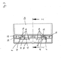
- a housing 2 is shown in a cross-sectional view.
- the housing 2 is composed of the lower part 4, on which the lid 6 is placed.
- the lower part 4 and the cover 6 are each a first and second housing component.
- the housing components can be connected to one another via the clamping elements 8. While in Fig. 1 the right clamping element 8 is shown in a latched position, the left clamping element 8 is shown in an open position.
- the clamping elements 8 have a tab 12 which surround a fixed axis 10 which is fixedly connected to the lower part 4. The tab 12 can be deducted in a pivoting position of the clamping element 8 of the fixed axis 10 when the clamping element 8 is to be completely removed from the corresponding housing member 4, 6.
- support surfaces 14 are formed, with which the lid 6 is supported on the respective fixed axis 10.
- the support surface 14 is formed on a stiffening rib 16.
- the support surface 14 may also be formed in other ways on a surface portion on the underside of the lid 6.
- the support surface 14 is free of play on the adjacent surface of the fixed axis 10. Since the support surface 14 of the peripheral contour the fixed axis 10 is adjusted, results in the embodiment in the region of the support surface 14 an uneven surface contact of the support surfaces 14 on the axis 10 as a connection between the lid 6 and the lower part 4. In a hinge-like pivotal movement of the lid 6 about the fixed axis 10th The support surfaces 14 slide over the surface of the fixed axis 10.
- a circumferential groove 18 is present on the cover 6, into which in the closed position of the cover 6, the spring 20, which is formed on the lower part 4, immersed. Due to the tongue and groove connection between the lower part 4 and the cover 6, the interior of the housing 2 is sealingly closed. In order to increase the seal in addition, in the groove 18 may be inserted a separate seal.
- a locking edge 26 is formed in the region of the clamping elements 8, which is engaged behind by a formed on the clamping element 8 locking lug 24 in the latched position of the clamping element 8.
- the locking lug 24 and the locking edge 26 form in this way a latching connection of the clamping element 8 with the lid. 6
- Fig. 2 the housing 2 is shown with a partially pivoted cover 6.
- the lid has been pivoted to the right fixed axis 10 as a hinge axis.
- the distance measure 28 between the fixed axis 10 partially encompassing tab 12 and the latch 24 of the left in Fig. 2 shown clamping element 8 is smaller than the distance 30 between the formed on the lid 6 locking edge 26 up to the side facing away from the locking edge 26 surface of the fixed axis 10 at the right in Fig. 2 shown clamping element 8.
- the clamping element 8 To the right in the housing part of the Fig. 2 To be able to assume the latched position shown, the clamping element 8 must therefore widen in its distance measure 28 to the distance measure 30.
- the tensioning element 8 builds up restoring forces due to the elasticity of the material used, as a result of which a tensile stress builds up between the lug 12 and the latching lug 24.
- tensile stress of the lid 6 is pressed with the support surfaces 14 on the fixed axis 10.
- the cover 6 is held by the clamping element 8 via the support surfaces 14 on the fixed axis 10 pivotally.
- the inner surface of the tab 12 forms, together with the support surfaces 14, a pivot bearing on the fixed axle 10, about which the cover 6 is pivotable.
- the fixed axis on the lower part 4 and the locking edge 26 is arranged on the cover 6, but the arrangement can also be reversed, in which case the tab of the clamping element 8, the fixed axis on the cover 6 and the locking lug 24, the locking lug on the lower part 4 surrounds ,
- Fig. 3 is a part of the housing 2 with the lid 6 shown from a top view.
- the clamping element 8 is in a swung-open position. From the top view, it can be seen that in the region of the lid edge 22, screw-on regions 32, bearing surfaces 34 and stiffening ribs 16 are located.
- Applied section line II corresponds substantially to a part of the sectional views according to Fig. 1 and Fig. 2 , Will that be in Fig. 3 Spheres shown 8 spent from the open pivot position in a locked position, the cover strip 36 of the clamping element 8 covers the Verschraubungs Suitee 32, the support surfaces 34 and the stiffening ribs 16.
- the am Clamping element 8 formed stiffening ribs 16 are no longer visible in the latched position of the clamping element 8.
- the clamping element 8 extends over the entire side length of the housing side, on which the clamping element is mounted. Through this length, it is possible to accommodate many functional elements such as screwed areas 32, bearing surfaces 34 and the like in the area of the lid edge 22 and to hide them in the latched position of the tensioning element 8 under the cover strip 36. In order to achieve a good force distribution between the lower part 4, the lid 6 and the clamping element 8, it is advantageous if the clamping element 8 extends over more than half the side length of the housing side, to which it is attached.
- two fixed axes 10 can be seen, which are partially encompassed by the associated tabs 12 of the clamping element 8.
- the fixed axes 10 are formed only in a partial section of the side wall of the lower part 4.
- support surfaces 14 are formed on the stiffening ribs 16. From the top view it can be seen that in the exemplary embodiment a total of six support surfaces 14 are formed on the cover side, via which the cover 6 is held in a suitably aligned position relative to the lower part 4. Also on the stiffening ribs 16, which are formed on the underside of the clamping element 8, corresponding support surfaces 14 may be formed.
- the clamping element 8 is in a latched position, the inner surface of the cover strip 36 rests on the bearing surfaces 34. In this way, the clamping element 8 and the cover strip 36 is well supported in the latched position.
- Corresponding bearing surfaces can also be formed on the inner surface of the clamping element 8 or on the stiffening ribs 16 formed on the clamping element 8.
Landscapes
- Engineering & Computer Science (AREA)
- Mechanical Engineering (AREA)
- Microelectronics & Electronic Packaging (AREA)
- Clamps And Clips (AREA)
- Pivots And Pivotal Connections (AREA)
- Casings For Electric Apparatus (AREA)
Applications Claiming Priority (1)
| Application Number | Priority Date | Filing Date | Title |
|---|---|---|---|
| DE102011116696A DE102011116696B3 (de) | 2011-10-24 | 2011-10-24 | Gehäuse mit einem Unterteil und einem Deckel |
Publications (3)
| Publication Number | Publication Date |
|---|---|
| EP2587901A2 true EP2587901A2 (fr) | 2013-05-01 |
| EP2587901A3 EP2587901A3 (fr) | 2017-11-15 |
| EP2587901B1 EP2587901B1 (fr) | 2019-03-27 |
Family
ID=46924203
Family Applications (1)
| Application Number | Title | Priority Date | Filing Date |
|---|---|---|---|
| EP12006276.5A Active EP2587901B1 (fr) | 2011-10-24 | 2012-09-06 | Boîtier avec une partie inférieure et un couvercle |
Country Status (5)
| Country | Link |
|---|---|
| EP (1) | EP2587901B1 (fr) |
| CN (1) | CN103057821A (fr) |
| DE (1) | DE102011116696B3 (fr) |
| ES (1) | ES2728711T3 (fr) |
| TW (1) | TWI559832B (fr) |
Cited By (1)
| Publication number | Priority date | Publication date | Assignee | Title |
|---|---|---|---|---|
| EP4546957A1 (fr) | 2023-10-25 | 2025-04-30 | bopla Gehäuse Systeme GmbH | Boîtier standard avec couvercle en matériau transparent ou translucide |
Families Citing this family (14)
| Publication number | Priority date | Publication date | Assignee | Title |
|---|---|---|---|---|
| US10351312B2 (en) | 2014-07-30 | 2019-07-16 | Iwasaki Industry Inc. | Storage container |
| EP2986090B1 (fr) * | 2014-08-12 | 2017-09-27 | bopla Gehäuse Systeme GmbH | Boîtier avec une partie inférieure et une partie supérieure |
| JP2016127164A (ja) * | 2015-01-05 | 2016-07-11 | ヤマハ株式会社 | 音響調節機器の筐体構造 |
| CN105173370B (zh) * | 2015-09-25 | 2017-07-28 | 安徽江淮汽车集团股份有限公司 | 盒体限位装置及盒体 |
| CA3006268A1 (fr) * | 2015-10-28 | 2017-05-04 | Crossford International, Llc | Applicateur de produit chimique solide a main |
| CN106102356A (zh) * | 2016-07-29 | 2016-11-09 | 方迪勇 | 一种led显示屏的翻盖式电器盒 |
| EP3580137A4 (fr) * | 2017-02-09 | 2021-08-11 | The Decor Corporation Pty. Ltd. | Récipient de stockage à pince |
| CN107189192A (zh) * | 2017-07-10 | 2017-09-22 | 清远芬乐桑拿泳池设备有限公司 | 一种水质监测仪壳体 |
| CN107396578B (zh) * | 2017-09-12 | 2023-05-16 | 珠海格力电器股份有限公司 | 电控箱的连接结构及电控箱 |
| CN109700334A (zh) * | 2019-02-26 | 2019-05-03 | 高亮 | 一种下翻盖烤箱 |
| DE102020102760A1 (de) | 2020-02-04 | 2021-08-05 | Jelenia Plast Sp. Z.O.O. | Kunststoffbehälter mit Deckel und Scharnier |
| LU102109B1 (de) | 2020-10-02 | 2022-04-04 | Phoenix Contact Gmbh & Co | Modularer Schaltschrank |
| DE102020125812A1 (de) | 2020-10-02 | 2022-04-07 | Phoenix Contact Gmbh & Co. Kg | Modularer Schaltschrank |
| CN116477186A (zh) * | 2023-05-05 | 2023-07-25 | 温岭市大江商场设施制造有限公司 | 一种运输安全的物流箱 |
Citations (1)
| Publication number | Priority date | Publication date | Assignee | Title |
|---|---|---|---|---|
| DE4405947C1 (de) | 1994-02-24 | 1995-03-30 | Bopla Gehaeuse Systeme Gmbh | Gehäuse mit Abdeckung und gegebenenfalls Zwischenrahmen |
Family Cites Families (7)
| Publication number | Priority date | Publication date | Assignee | Title |
|---|---|---|---|---|
| US4270668A (en) * | 1980-02-05 | 1981-06-02 | Shop-Vac Corporation | Buckle or latch for holding lid to container |
| US5125697A (en) * | 1990-11-29 | 1992-06-30 | Rubbermaid Incorporated | Lockable latch for a container |
| DE19641123A1 (de) * | 1996-10-05 | 1998-04-16 | Wolf Hans Joachim | Behälterelement mit einem Funktionsteil zur Handhabung, insbesondere Verschluß oder Transport desselben |
| JP4329982B2 (ja) * | 2002-10-18 | 2009-09-09 | 天馬株式会社 | 蓋付収納箱 |
| DE202009014800U1 (de) * | 2009-11-03 | 2010-02-18 | Rose Systemtechnik Gmbh | Gehäuse |
| TWM385897U (en) * | 2010-01-29 | 2010-08-01 | Universal Scient Ind Shanghai | Housing having receiving mechanism and electronic device including the same |
| TWM385731U (en) * | 2010-03-05 | 2010-08-01 | Inventec Corp | Structure for fixing screen onto tablet computers |
-
2011
- 2011-10-24 DE DE102011116696A patent/DE102011116696B3/de not_active Expired - Fee Related
-
2012
- 2012-09-06 EP EP12006276.5A patent/EP2587901B1/fr active Active
- 2012-09-06 ES ES12006276T patent/ES2728711T3/es active Active
- 2012-10-19 TW TW101138544A patent/TWI559832B/zh active
- 2012-10-24 CN CN2012104080580A patent/CN103057821A/zh active Pending
Patent Citations (1)
| Publication number | Priority date | Publication date | Assignee | Title |
|---|---|---|---|---|
| DE4405947C1 (de) | 1994-02-24 | 1995-03-30 | Bopla Gehaeuse Systeme Gmbh | Gehäuse mit Abdeckung und gegebenenfalls Zwischenrahmen |
Cited By (1)
| Publication number | Priority date | Publication date | Assignee | Title |
|---|---|---|---|---|
| EP4546957A1 (fr) | 2023-10-25 | 2025-04-30 | bopla Gehäuse Systeme GmbH | Boîtier standard avec couvercle en matériau transparent ou translucide |
Also Published As
| Publication number | Publication date |
|---|---|
| TWI559832B (zh) | 2016-11-21 |
| CN103057821A (zh) | 2013-04-24 |
| EP2587901B1 (fr) | 2019-03-27 |
| EP2587901A3 (fr) | 2017-11-15 |
| ES2728711T3 (es) | 2019-10-28 |
| DE102011116696B3 (de) | 2012-12-20 |
| TW201332415A (zh) | 2013-08-01 |
Similar Documents
| Publication | Publication Date | Title |
|---|---|---|
| DE102011116696B3 (de) | Gehäuse mit einem Unterteil und einem Deckel | |
| DE10246527B4 (de) | Klemmvorrichtung für ein Radnabenlager | |
| EP1636439A1 (fr) | Dispositif d'evacuation des eaux de ruissellement | |
| EP3329145B1 (fr) | Sangle ou segment de sangle | |
| DE202012001760U1 (de) | Kabelführung | |
| DE102007061641A1 (de) | Ablenkeinrichtung | |
| DE102012101614A1 (de) | Vorrichtung zum Verschließen eines Gehäuses eines Steckverbinders | |
| EP3203124A1 (fr) | Élément de membrane en élastomère | |
| DE102013106385B4 (de) | Scharniervorrichtung | |
| EP3776772B1 (fr) | Bande de séparation pour une chaîne porte-câbles | |
| DE102008047322A1 (de) | Schutz-und Führungsvorrichtung für ein Kabel oder dergleichen | |
| DE112007000255T5 (de) | Verbindungselement an einem Wischerblatt | |
| DE102018201493B4 (de) | Verkleidungsteil für ein Kraftfahrzeug und Verwendung | |
| DE102010017424A1 (de) | Vorrichtung zum Verriegeln einer Abdeckung | |
| DE102012013731A1 (de) | Wasserablaufventil für den Wasserkasten eines Kraftfahrzeuges | |
| DE102008047323A1 (de) | Schutz-und Führungsvorrichtung für ein Kabel oder dergleichen | |
| DE102012218339A1 (de) | Vorrichtung zum Verbinden von wenigstens zwei Elementen | |
| WO2011057821A2 (fr) | Dispositif de serrage | |
| EP3447205B1 (fr) | Mise en place d'une couverture sur une gouttière | |
| DE102009033549A1 (de) | Befestigungselement | |
| DE29915560U1 (de) | Schraubensicherung | |
| DE102019204586A1 (de) | Lenkgehäuse | |
| DE102008025093A1 (de) | Sicherheitsgurt-Umlenkelement mit einstückigem Verkleidungsteil | |
| DE4335868C1 (de) | Parkkarte zur gebührenpflichtigen Betätigung einer Parkschranke | |
| DE202006009179U1 (de) | Abdeckklappe und Anordnung aus Abdeckklappe und Montagerahmen |
Legal Events
| Date | Code | Title | Description |
|---|---|---|---|
| PUAI | Public reference made under article 153(3) epc to a published international application that has entered the european phase |
Free format text: ORIGINAL CODE: 0009012 |
|
| AK | Designated contracting states |
Kind code of ref document: A2 Designated state(s): AL AT BE BG CH CY CZ DE DK EE ES FI FR GB GR HR HU IE IS IT LI LT LU LV MC MK MT NL NO PL PT RO RS SE SI SK SM TR |
|
| AX | Request for extension of the european patent |
Extension state: BA ME |
|
| PUAL | Search report despatched |
Free format text: ORIGINAL CODE: 0009013 |
|
| AK | Designated contracting states |
Kind code of ref document: A3 Designated state(s): AL AT BE BG CH CY CZ DE DK EE ES FI FR GB GR HR HU IE IS IT LI LT LU LV MC MK MT NL NO PL PT RO RS SE SI SK SM TR |
|
| AX | Request for extension of the european patent |
Extension state: BA ME |
|
| RIC1 | Information provided on ipc code assigned before grant |
Ipc: H05K 5/00 20060101AFI20171009BHEP Ipc: B65D 43/02 20060101ALN20171009BHEP Ipc: H05K 5/02 20060101ALI20171009BHEP Ipc: B65D 45/20 20060101ALN20171009BHEP Ipc: B65D 43/16 20060101ALN20171009BHEP |
|
| STAA | Information on the status of an ep patent application or granted ep patent |
Free format text: STATUS: REQUEST FOR EXAMINATION WAS MADE |
|
| 17P | Request for examination filed |
Effective date: 20171113 |
|
| RBV | Designated contracting states (corrected) |
Designated state(s): AL AT BE BG CH CY CZ DE DK EE ES FI FR GB GR HR HU IE IS IT LI LT LU LV MC MK MT NL NO PL PT RO RS SE SI SK SM TR |
|
| GRAP | Despatch of communication of intention to grant a patent |
Free format text: ORIGINAL CODE: EPIDOSNIGR1 |
|
| STAA | Information on the status of an ep patent application or granted ep patent |
Free format text: STATUS: GRANT OF PATENT IS INTENDED |
|
| RIC1 | Information provided on ipc code assigned before grant |
Ipc: H05K 5/00 20060101AFI20181122BHEP Ipc: H05K 5/02 20060101ALI20181122BHEP Ipc: B65D 43/02 20060101ALN20181122BHEP Ipc: B65D 43/16 20060101ALN20181122BHEP Ipc: B65D 45/20 20060101ALN20181122BHEP |
|
| INTG | Intention to grant announced |
Effective date: 20181214 |
|
| GRAS | Grant fee paid |
Free format text: ORIGINAL CODE: EPIDOSNIGR3 |
|
| GRAA | (expected) grant |
Free format text: ORIGINAL CODE: 0009210 |
|
| STAA | Information on the status of an ep patent application or granted ep patent |
Free format text: STATUS: THE PATENT HAS BEEN GRANTED |
|
| AK | Designated contracting states |
Kind code of ref document: B1 Designated state(s): AL AT BE BG CH CY CZ DE DK EE ES FI FR GB GR HR HU IE IS IT LI LT LU LV MC MK MT NL NO PL PT RO RS SE SI SK SM TR |
|
| REG | Reference to a national code |
Ref country code: GB Ref legal event code: FG4D Free format text: NOT ENGLISH |
|
| REG | Reference to a national code |
Ref country code: CH Ref legal event code: EP |
|
| REG | Reference to a national code |
Ref country code: DE Ref legal event code: R096 Ref document number: 502012014487 Country of ref document: DE |
|
| REG | Reference to a national code |
Ref country code: AT Ref legal event code: REF Ref document number: 1114571 Country of ref document: AT Kind code of ref document: T Effective date: 20190415 |
|
| REG | Reference to a national code |
Ref country code: IE Ref legal event code: FG4D Free format text: LANGUAGE OF EP DOCUMENT: GERMAN |
|
| PG25 | Lapsed in a contracting state [announced via postgrant information from national office to epo] |
Ref country code: NO Free format text: LAPSE BECAUSE OF FAILURE TO SUBMIT A TRANSLATION OF THE DESCRIPTION OR TO PAY THE FEE WITHIN THE PRESCRIBED TIME-LIMIT Effective date: 20190627 Ref country code: FI Free format text: LAPSE BECAUSE OF FAILURE TO SUBMIT A TRANSLATION OF THE DESCRIPTION OR TO PAY THE FEE WITHIN THE PRESCRIBED TIME-LIMIT Effective date: 20190327 Ref country code: LT Free format text: LAPSE BECAUSE OF FAILURE TO SUBMIT A TRANSLATION OF THE DESCRIPTION OR TO PAY THE FEE WITHIN THE PRESCRIBED TIME-LIMIT Effective date: 20190327 Ref country code: SE Free format text: LAPSE BECAUSE OF FAILURE TO SUBMIT A TRANSLATION OF THE DESCRIPTION OR TO PAY THE FEE WITHIN THE PRESCRIBED TIME-LIMIT Effective date: 20190327 |
|
| REG | Reference to a national code |
Ref country code: NL Ref legal event code: MP Effective date: 20190327 |
|
| PG25 | Lapsed in a contracting state [announced via postgrant information from national office to epo] |
Ref country code: NL Free format text: LAPSE BECAUSE OF FAILURE TO SUBMIT A TRANSLATION OF THE DESCRIPTION OR TO PAY THE FEE WITHIN THE PRESCRIBED TIME-LIMIT Effective date: 20190327 Ref country code: BG Free format text: LAPSE BECAUSE OF FAILURE TO SUBMIT A TRANSLATION OF THE DESCRIPTION OR TO PAY THE FEE WITHIN THE PRESCRIBED TIME-LIMIT Effective date: 20190627 Ref country code: RS Free format text: LAPSE BECAUSE OF FAILURE TO SUBMIT A TRANSLATION OF THE DESCRIPTION OR TO PAY THE FEE WITHIN THE PRESCRIBED TIME-LIMIT Effective date: 20190327 Ref country code: LV Free format text: LAPSE BECAUSE OF FAILURE TO SUBMIT A TRANSLATION OF THE DESCRIPTION OR TO PAY THE FEE WITHIN THE PRESCRIBED TIME-LIMIT Effective date: 20190327 Ref country code: HR Free format text: LAPSE BECAUSE OF FAILURE TO SUBMIT A TRANSLATION OF THE DESCRIPTION OR TO PAY THE FEE WITHIN THE PRESCRIBED TIME-LIMIT Effective date: 20190327 Ref country code: GR Free format text: LAPSE BECAUSE OF FAILURE TO SUBMIT A TRANSLATION OF THE DESCRIPTION OR TO PAY THE FEE WITHIN THE PRESCRIBED TIME-LIMIT Effective date: 20190628 |
|
| REG | Reference to a national code |
Ref country code: ES Ref legal event code: FG2A Ref document number: 2728711 Country of ref document: ES Kind code of ref document: T3 Effective date: 20191028 |
|
| PG25 | Lapsed in a contracting state [announced via postgrant information from national office to epo] |
Ref country code: PT Free format text: LAPSE BECAUSE OF FAILURE TO SUBMIT A TRANSLATION OF THE DESCRIPTION OR TO PAY THE FEE WITHIN THE PRESCRIBED TIME-LIMIT Effective date: 20190727 Ref country code: EE Free format text: LAPSE BECAUSE OF FAILURE TO SUBMIT A TRANSLATION OF THE DESCRIPTION OR TO PAY THE FEE WITHIN THE PRESCRIBED TIME-LIMIT Effective date: 20190327 Ref country code: AL Free format text: LAPSE BECAUSE OF FAILURE TO SUBMIT A TRANSLATION OF THE DESCRIPTION OR TO PAY THE FEE WITHIN THE PRESCRIBED TIME-LIMIT Effective date: 20190327 Ref country code: RO Free format text: LAPSE BECAUSE OF FAILURE TO SUBMIT A TRANSLATION OF THE DESCRIPTION OR TO PAY THE FEE WITHIN THE PRESCRIBED TIME-LIMIT Effective date: 20190327 Ref country code: SK Free format text: LAPSE BECAUSE OF FAILURE TO SUBMIT A TRANSLATION OF THE DESCRIPTION OR TO PAY THE FEE WITHIN THE PRESCRIBED TIME-LIMIT Effective date: 20190327 Ref country code: IT Free format text: LAPSE BECAUSE OF FAILURE TO SUBMIT A TRANSLATION OF THE DESCRIPTION OR TO PAY THE FEE WITHIN THE PRESCRIBED TIME-LIMIT Effective date: 20190327 Ref country code: CZ Free format text: LAPSE BECAUSE OF FAILURE TO SUBMIT A TRANSLATION OF THE DESCRIPTION OR TO PAY THE FEE WITHIN THE PRESCRIBED TIME-LIMIT Effective date: 20190327 |
|
| PG25 | Lapsed in a contracting state [announced via postgrant information from national office to epo] |
Ref country code: SM Free format text: LAPSE BECAUSE OF FAILURE TO SUBMIT A TRANSLATION OF THE DESCRIPTION OR TO PAY THE FEE WITHIN THE PRESCRIBED TIME-LIMIT Effective date: 20190327 Ref country code: PL Free format text: LAPSE BECAUSE OF FAILURE TO SUBMIT A TRANSLATION OF THE DESCRIPTION OR TO PAY THE FEE WITHIN THE PRESCRIBED TIME-LIMIT Effective date: 20190327 |
|
| PG25 | Lapsed in a contracting state [announced via postgrant information from national office to epo] |
Ref country code: IS Free format text: LAPSE BECAUSE OF FAILURE TO SUBMIT A TRANSLATION OF THE DESCRIPTION OR TO PAY THE FEE WITHIN THE PRESCRIBED TIME-LIMIT Effective date: 20190727 |
|
| REG | Reference to a national code |
Ref country code: DE Ref legal event code: R097 Ref document number: 502012014487 Country of ref document: DE |
|
| PG25 | Lapsed in a contracting state [announced via postgrant information from national office to epo] |
Ref country code: DK Free format text: LAPSE BECAUSE OF FAILURE TO SUBMIT A TRANSLATION OF THE DESCRIPTION OR TO PAY THE FEE WITHIN THE PRESCRIBED TIME-LIMIT Effective date: 20190327 |
|
| PLBE | No opposition filed within time limit |
Free format text: ORIGINAL CODE: 0009261 |
|
| STAA | Information on the status of an ep patent application or granted ep patent |
Free format text: STATUS: NO OPPOSITION FILED WITHIN TIME LIMIT |
|
| PG25 | Lapsed in a contracting state [announced via postgrant information from national office to epo] |
Ref country code: SI Free format text: LAPSE BECAUSE OF FAILURE TO SUBMIT A TRANSLATION OF THE DESCRIPTION OR TO PAY THE FEE WITHIN THE PRESCRIBED TIME-LIMIT Effective date: 20190327 |
|
| 26N | No opposition filed |
Effective date: 20200103 |
|
| PG25 | Lapsed in a contracting state [announced via postgrant information from national office to epo] |
Ref country code: TR Free format text: LAPSE BECAUSE OF FAILURE TO SUBMIT A TRANSLATION OF THE DESCRIPTION OR TO PAY THE FEE WITHIN THE PRESCRIBED TIME-LIMIT Effective date: 20190327 |
|
| PG25 | Lapsed in a contracting state [announced via postgrant information from national office to epo] |
Ref country code: MC Free format text: LAPSE BECAUSE OF FAILURE TO SUBMIT A TRANSLATION OF THE DESCRIPTION OR TO PAY THE FEE WITHIN THE PRESCRIBED TIME-LIMIT Effective date: 20190327 |
|
| REG | Reference to a national code |
Ref country code: CH Ref legal event code: PL |
|
| PG25 | Lapsed in a contracting state [announced via postgrant information from national office to epo] |
Ref country code: IE Free format text: LAPSE BECAUSE OF NON-PAYMENT OF DUE FEES Effective date: 20190906 Ref country code: CH Free format text: LAPSE BECAUSE OF NON-PAYMENT OF DUE FEES Effective date: 20190930 Ref country code: LI Free format text: LAPSE BECAUSE OF NON-PAYMENT OF DUE FEES Effective date: 20190930 Ref country code: LU Free format text: LAPSE BECAUSE OF NON-PAYMENT OF DUE FEES Effective date: 20190906 |
|
| REG | Reference to a national code |
Ref country code: BE Ref legal event code: MM Effective date: 20190930 |
|
| PG25 | Lapsed in a contracting state [announced via postgrant information from national office to epo] |
Ref country code: BE Free format text: LAPSE BECAUSE OF NON-PAYMENT OF DUE FEES Effective date: 20190930 |
|
| REG | Reference to a national code |
Ref country code: AT Ref legal event code: MM01 Ref document number: 1114571 Country of ref document: AT Kind code of ref document: T Effective date: 20190906 |
|
| PG25 | Lapsed in a contracting state [announced via postgrant information from national office to epo] |
Ref country code: AT Free format text: LAPSE BECAUSE OF NON-PAYMENT OF DUE FEES Effective date: 20190906 |
|
| PG25 | Lapsed in a contracting state [announced via postgrant information from national office to epo] |
Ref country code: CY Free format text: LAPSE BECAUSE OF FAILURE TO SUBMIT A TRANSLATION OF THE DESCRIPTION OR TO PAY THE FEE WITHIN THE PRESCRIBED TIME-LIMIT Effective date: 20190327 |
|
| PG25 | Lapsed in a contracting state [announced via postgrant information from national office to epo] |
Ref country code: MT Free format text: LAPSE BECAUSE OF FAILURE TO SUBMIT A TRANSLATION OF THE DESCRIPTION OR TO PAY THE FEE WITHIN THE PRESCRIBED TIME-LIMIT Effective date: 20190327 Ref country code: HU Free format text: LAPSE BECAUSE OF FAILURE TO SUBMIT A TRANSLATION OF THE DESCRIPTION OR TO PAY THE FEE WITHIN THE PRESCRIBED TIME-LIMIT; INVALID AB INITIO Effective date: 20120906 |
|
| PG25 | Lapsed in a contracting state [announced via postgrant information from national office to epo] |
Ref country code: MK Free format text: LAPSE BECAUSE OF FAILURE TO SUBMIT A TRANSLATION OF THE DESCRIPTION OR TO PAY THE FEE WITHIN THE PRESCRIBED TIME-LIMIT Effective date: 20190327 |
|
| PGFP | Annual fee paid to national office [announced via postgrant information from national office to epo] |
Ref country code: DE Payment date: 20250611 Year of fee payment: 14 |
|
| PGFP | Annual fee paid to national office [announced via postgrant information from national office to epo] |
Ref country code: GB Payment date: 20250923 Year of fee payment: 14 |
|
| PGFP | Annual fee paid to national office [announced via postgrant information from national office to epo] |
Ref country code: FR Payment date: 20250924 Year of fee payment: 14 |
|
| PGFP | Annual fee paid to national office [announced via postgrant information from national office to epo] |
Ref country code: ES Payment date: 20251020 Year of fee payment: 14 |