EP2588907B1 - Connecteur de type mpo possédant une charge hors centre réduite - Google Patents
Connecteur de type mpo possédant une charge hors centre réduite Download PDFInfo
- Publication number
- EP2588907B1 EP2588907B1 EP11740756.9A EP11740756A EP2588907B1 EP 2588907 B1 EP2588907 B1 EP 2588907B1 EP 11740756 A EP11740756 A EP 11740756A EP 2588907 B1 EP2588907 B1 EP 2588907B1
- Authority
- EP
- European Patent Office
- Prior art keywords
- ferrule
- pin clamp
- spring
- internal assembly
- fiber array
- Prior art date
- Legal status (The legal status is an assumption and is not a legal conclusion. Google has not performed a legal analysis and makes no representation as to the accuracy of the status listed.)
- Active
Links
Images






Classifications
-
- G—PHYSICS
- G02—OPTICS
- G02B—OPTICAL ELEMENTS, SYSTEMS OR APPARATUS
- G02B6/00—Light guides; Structural details of arrangements comprising light guides and other optical elements, e.g. couplings
- G02B6/24—Coupling light guides
- G02B6/36—Mechanical coupling means
- G02B6/38—Mechanical coupling means having fibre to fibre mating means
- G02B6/3807—Dismountable connectors, i.e. comprising plugs
- G02B6/3873—Connectors using guide surfaces for aligning ferrule ends, e.g. tubes, sleeves, V-grooves, rods, pins, balls
- G02B6/3885—Multicore or multichannel optical connectors, i.e. one single ferrule containing more than one fibre, e.g. ribbon type
-
- G—PHYSICS
- G02—OPTICS
- G02B—OPTICAL ELEMENTS, SYSTEMS OR APPARATUS
- G02B6/00—Light guides; Structural details of arrangements comprising light guides and other optical elements, e.g. couplings
- G02B6/24—Coupling light guides
- G02B6/42—Coupling light guides with opto-electronic elements
- G02B6/4201—Packages, e.g. shape, construction, internal or external details
-
- G—PHYSICS
- G02—OPTICS
- G02B—OPTICAL ELEMENTS, SYSTEMS OR APPARATUS
- G02B6/00—Light guides; Structural details of arrangements comprising light guides and other optical elements, e.g. couplings
- G02B6/24—Coupling light guides
- G02B6/42—Coupling light guides with opto-electronic elements
- G02B6/4201—Packages, e.g. shape, construction, internal or external details
- G02B6/4202—Packages, e.g. shape, construction, internal or external details for coupling an active element with fibres without intermediate optical elements, e.g. fibres with plane ends, fibres with shaped ends, bundles
-
- G—PHYSICS
- G02—OPTICS
- G02B—OPTICAL ELEMENTS, SYSTEMS OR APPARATUS
- G02B6/00—Light guides; Structural details of arrangements comprising light guides and other optical elements, e.g. couplings
- G02B6/24—Coupling light guides
- G02B6/42—Coupling light guides with opto-electronic elements
- G02B6/4201—Packages, e.g. shape, construction, internal or external details
- G02B6/4202—Packages, e.g. shape, construction, internal or external details for coupling an active element with fibres without intermediate optical elements, e.g. fibres with plane ends, fibres with shaped ends, bundles
- G02B6/4203—Optical features
-
- G—PHYSICS
- G02—OPTICS
- G02B—OPTICAL ELEMENTS, SYSTEMS OR APPARATUS
- G02B6/00—Light guides; Structural details of arrangements comprising light guides and other optical elements, e.g. couplings
- G02B6/24—Coupling light guides
- G02B6/42—Coupling light guides with opto-electronic elements
- G02B6/4201—Packages, e.g. shape, construction, internal or external details
- G02B6/4204—Packages, e.g. shape, construction, internal or external details the coupling comprising intermediate optical elements, e.g. lenses, holograms
-
- G—PHYSICS
- G02—OPTICS
- G02B—OPTICAL ELEMENTS, SYSTEMS OR APPARATUS
- G02B6/00—Light guides; Structural details of arrangements comprising light guides and other optical elements, e.g. couplings
- G02B6/24—Coupling light guides
- G02B6/42—Coupling light guides with opto-electronic elements
- G02B6/4201—Packages, e.g. shape, construction, internal or external details
- G02B6/4204—Packages, e.g. shape, construction, internal or external details the coupling comprising intermediate optical elements, e.g. lenses, holograms
- G02B6/4206—Optical features
-
- G—PHYSICS
- G02—OPTICS
- G02B—OPTICAL ELEMENTS, SYSTEMS OR APPARATUS
- G02B6/00—Light guides; Structural details of arrangements comprising light guides and other optical elements, e.g. couplings
- G02B6/24—Coupling light guides
- G02B6/42—Coupling light guides with opto-electronic elements
- G02B6/4201—Packages, e.g. shape, construction, internal or external details
- G02B6/4204—Packages, e.g. shape, construction, internal or external details the coupling comprising intermediate optical elements, e.g. lenses, holograms
- G02B6/4207—Packages, e.g. shape, construction, internal or external details the coupling comprising intermediate optical elements, e.g. lenses, holograms with optical elements reducing the sensitivity to optical feedback
-
- G—PHYSICS
- G02—OPTICS
- G02B—OPTICAL ELEMENTS, SYSTEMS OR APPARATUS
- G02B6/00—Light guides; Structural details of arrangements comprising light guides and other optical elements, e.g. couplings
- G02B6/24—Coupling light guides
- G02B6/42—Coupling light guides with opto-electronic elements
- G02B6/4201—Packages, e.g. shape, construction, internal or external details
- G02B6/4204—Packages, e.g. shape, construction, internal or external details the coupling comprising intermediate optical elements, e.g. lenses, holograms
- G02B6/4207—Packages, e.g. shape, construction, internal or external details the coupling comprising intermediate optical elements, e.g. lenses, holograms with optical elements reducing the sensitivity to optical feedback
- G02B6/4208—Packages, e.g. shape, construction, internal or external details the coupling comprising intermediate optical elements, e.g. lenses, holograms with optical elements reducing the sensitivity to optical feedback using non-reciprocal elements or birefringent plates, i.e. quasi-isolators
-
- G—PHYSICS
- G02—OPTICS
- G02B—OPTICAL ELEMENTS, SYSTEMS OR APPARATUS
- G02B6/00—Light guides; Structural details of arrangements comprising light guides and other optical elements, e.g. couplings
- G02B6/24—Coupling light guides
- G02B6/42—Coupling light guides with opto-electronic elements
- G02B6/4201—Packages, e.g. shape, construction, internal or external details
- G02B6/4204—Packages, e.g. shape, construction, internal or external details the coupling comprising intermediate optical elements, e.g. lenses, holograms
- G02B6/4207—Packages, e.g. shape, construction, internal or external details the coupling comprising intermediate optical elements, e.g. lenses, holograms with optical elements reducing the sensitivity to optical feedback
- G02B6/4208—Packages, e.g. shape, construction, internal or external details the coupling comprising intermediate optical elements, e.g. lenses, holograms with optical elements reducing the sensitivity to optical feedback using non-reciprocal elements or birefringent plates, i.e. quasi-isolators
- G02B6/4209—Optical features
-
- G—PHYSICS
- G02—OPTICS
- G02B—OPTICAL ELEMENTS, SYSTEMS OR APPARATUS
- G02B6/00—Light guides; Structural details of arrangements comprising light guides and other optical elements, e.g. couplings
- G02B6/24—Coupling light guides
- G02B6/42—Coupling light guides with opto-electronic elements
- G02B6/4201—Packages, e.g. shape, construction, internal or external details
- G02B6/4204—Packages, e.g. shape, construction, internal or external details the coupling comprising intermediate optical elements, e.g. lenses, holograms
- G02B6/421—Packages, e.g. shape, construction, internal or external details the coupling comprising intermediate optical elements, e.g. lenses, holograms the intermediate optical component consisting of a short length of fibre, e.g. fibre stub
-
- G—PHYSICS
- G02—OPTICS
- G02B—OPTICAL ELEMENTS, SYSTEMS OR APPARATUS
- G02B6/00—Light guides; Structural details of arrangements comprising light guides and other optical elements, e.g. couplings
- G02B6/24—Coupling light guides
- G02B6/42—Coupling light guides with opto-electronic elements
- G02B6/4201—Packages, e.g. shape, construction, internal or external details
- G02B6/4204—Packages, e.g. shape, construction, internal or external details the coupling comprising intermediate optical elements, e.g. lenses, holograms
- G02B6/4212—Packages, e.g. shape, construction, internal or external details the coupling comprising intermediate optical elements, e.g. lenses, holograms the intermediate optical element being a coupling medium interposed therebetween, e.g. epoxy resin, refractive index matching material, index grease, matching liquid or gel
-
- G—PHYSICS
- G02—OPTICS
- G02B—OPTICAL ELEMENTS, SYSTEMS OR APPARATUS
- G02B6/00—Light guides; Structural details of arrangements comprising light guides and other optical elements, e.g. couplings
- G02B6/24—Coupling light guides
- G02B6/42—Coupling light guides with opto-electronic elements
- G02B6/4201—Packages, e.g. shape, construction, internal or external details
- G02B6/4204—Packages, e.g. shape, construction, internal or external details the coupling comprising intermediate optical elements, e.g. lenses, holograms
- G02B6/4214—Packages, e.g. shape, construction, internal or external details the coupling comprising intermediate optical elements, e.g. lenses, holograms the intermediate optical element having redirecting reflective means, e.g. mirrors, prisms for deflecting the radiation from horizontal to down- or upward direction toward a device
-
- G—PHYSICS
- G02—OPTICS
- G02B—OPTICAL ELEMENTS, SYSTEMS OR APPARATUS
- G02B6/00—Light guides; Structural details of arrangements comprising light guides and other optical elements, e.g. couplings
- G02B6/24—Coupling light guides
- G02B6/36—Mechanical coupling means
- G02B6/38—Mechanical coupling means having fibre to fibre mating means
- G02B6/3807—Dismountable connectors, i.e. comprising plugs
- G02B6/381—Dismountable connectors, i.e. comprising plugs of the ferrule type, e.g. fibre ends embedded in ferrules, connecting a pair of fibres
- G02B6/3818—Dismountable connectors, i.e. comprising plugs of the ferrule type, e.g. fibre ends embedded in ferrules, connecting a pair of fibres of a low-reflection-loss type
- G02B6/3821—Dismountable connectors, i.e. comprising plugs of the ferrule type, e.g. fibre ends embedded in ferrules, connecting a pair of fibres of a low-reflection-loss type with axial spring biasing or loading means
-
- G—PHYSICS
- G02—OPTICS
- G02B—OPTICAL ELEMENTS, SYSTEMS OR APPARATUS
- G02B6/00—Light guides; Structural details of arrangements comprising light guides and other optical elements, e.g. couplings
- G02B6/24—Coupling light guides
- G02B6/36—Mechanical coupling means
- G02B6/38—Mechanical coupling means having fibre to fibre mating means
- G02B6/3807—Dismountable connectors, i.e. comprising plugs
- G02B6/3873—Connectors using guide surfaces for aligning ferrule ends, e.g. tubes, sleeves, V-grooves, rods, pins, balls
- G02B6/3882—Connectors using guide surfaces for aligning ferrule ends, e.g. tubes, sleeves, V-grooves, rods, pins, balls using rods, pins or balls to align a pair of ferrule ends
- G02B6/3883—Connectors using guide surfaces for aligning ferrule ends, e.g. tubes, sleeves, V-grooves, rods, pins, balls using rods, pins or balls to align a pair of ferrule ends using rods, pins or balls to align a plurality of pairs of ferrule ends
Definitions
- the present invention relates generally to multifiber push on (MPO) type connectors and specifically to an internal assembly for an MPO type connector which directs the spring load on the ferrule closer to the longitudinal centerline of the connector.
- MPO multifiber push on
- MPO type connectors are becoming increasingly popular due to demands for increased density and the development of high-speed multifiber (multilane) data transmission protocols. These demands are even causing MPO connectors with fiber counts greater than 12 to be manufactured. However, this increasing fiber count density makes MPO connectors even more susceptible to rocking effects created by off-center loading. Off-center loading creates uneven pressure on the ferrule end face, resulting in reduced physical contact and causing increased insertion loss and decreased return loss.
- Past solutions have generally included increasing the load to the ferrule applied by the spring; however, increasing the load per fiber to ensure a good physical contact is generally not desired because it causes high stress at the fiber tips and can cause fiber damage or fiber pistoning when applied over time.
- US 2005/0069264 describes a fiber optic connector including a multifiber ferrule and at least one force centering element for applying a biasing force to the ferrule in the longitudinal direction without introducing a moment about a lateral axis.
- the connector further includes a coil spring for exerting the biasing force and a spring seat disposed between the coil spring and the ferrule.
- the rearward portion or the forward portion of the spring seat may be provided with a pair of outwardly extending protrusions that are laterally spaced apart to transfer the biasing force to the ferrule.
- the forward portion of the spring seat or the rear face of the ferrule may define a convex surface.
- the ferrule defines a convex surface in the direction of a first lateral axis and the spring seat defines a convex surface in the direction of a second lateral axis perpendicular to the first lateral axis.
- US 2004/0117981 describes a ferrule assembly for terminating at least one fiber of a ribbon cable in a ferrule, where the ferrule assembly is disposable in a housing of an optical connector.
- the ferrule assembly includes the ferrule having a mating face, at least one groove for receiving the fiber and at least one through-hole.
- the ferrule assembly also includes an alignment member holder having at least one alignment member and providing a first channel for the ribbon cable, the alignment member being insertable in the through-hole of the ferrule and having a first length such that an end of the alignment member extends beyond the mating face of the ferrule when the ferrule assembly is assembled.
- the ferrule assembly further includes a carrier body attachable to the alignment member holder, the carrier body having at least two biasing member capture portions, each of the biasing member capture portions providing an opening for capturing a biasing member therein when the alignment member holder and the carrier body are attached.
- the carrier body further provides a second channel for the ribbon cable, the second channel being disposed between the biasing member capture portions of the carrier body and being contiguous with the first channel when the alignment member holder and the carrier body are attached.
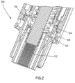
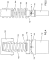
- Figures 1-9 show an MPO connector 100 with reduced off-center loading.
- the internal assembly of the connector comprises a spring push 102 (shown in Figures 4 and 5 ), a spring 104, a fiber array 106, a ferrule boot 108, a pin clamp 110, a ferrule 112 (in one embodiment, the ferrule can be a standard FOCIS-5 compliant ferrule), and a plurality of polished fiber tips 114 (shown in Figure 7 ).
- the fiber count can be from 1 to 72 or more fibers.
- the spring 104 can encircle the fiber array 106 and engage the spring push 102 at one end, and the pin clamp 110 at the other end. As highlighted in Figures 6a and 6b , the spring 104 sits in a spring clamp pocket 116 to centrally locate the contact surface about the center of the ferrule 112.
- the pin clamp 110 transfers the load from the spring 104 to the ferrule 112.
- the pin clamp 110 contacts the back of the ferrule 112 via a pair of contact surfaces 118.
- the contact surfaces 118 are located along the mid-point of the height of the ferrule 112 (in Figures 4-9 , the contact surfaces are along the x-axis, the x-axis being in the direction of the width of the ferrule and the y-axis being the direction of the height of the ferrule) and on either side of the fiber array 106 as close to the centerline of the width (as close to the y-axis) as allowed by the size of the fiber array 106.
- This design prevents any substantial off-center loading in the y-direction of the ferrule 112 and limits off-center loading in the x-direction.
- the contact surfaces can be extended such that contact is made with the ferrule outside of the alignment holes 122 (see Figure 6a and 6b ) in addition to or instead of in between each alignment hole 122 and the fiber array 106 in order to make the pin clamp 110 more robust.
- the next popular fiber count after 12 is 24, which employs two rows of 12 fibers each.
- Figure 7 shows a front connector face for a 24 count MPO connector.
- Figures 8 and 9 show how the force created by the spring 104 is centered on the ferrule 112 by the pin clamp 110, resulting in reaction forces on the front of the ferrule 112 where the fiber tips 114 are located.
- the location of the offset force in the y-direction is significantly reduced, in some embodiments, by as much as 1.5 mm from both the top and bottom for a standard 24 count MPO connector.
- the offset in the x-direction is also reduced by approximately 0.5 mm from each side.
- the reduction in the offset in the y-direction reduces any moments applied about the x-axis, which improves the fiber contact between rows.
- the reduction of offset in the x direction reduces moments applied about the y-axis, which improves the fiber contact between quadrants.
- the objective is to minimize the moment created along the x and y centerlines of the ferrule.
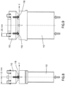
- Figures 10-14 show an example of a connector with reduced off-center loading in which the contact surfaces 118 are instead located along the mid-point of the width of the ferrule 112 (in Figures 10-14 , the contact points are along the y-axis, the y-axis being the direction of the height of the ferrule and the x-axis being in the direction of the width of the ferrule) and on either side of the fiber array 106, as close to the centerline of the height (as close to the x-axis) as allowed by the size of the fiber array 106.
- Figures 13 and 14 show how the offset force in the x-direction is significantly reduced, as much as by 2.4 mm from both sides for a standard 24 count MPO connector.
- the offset in the y-direction is also reduced by approximately 0.6 mm from both the top and bottom.
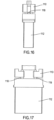
- Figures 15-17 show a second alternate embodiment in which the raised surfaces 118 can be located on the ferrule 112 instead of the pin clamp 110.
- Figures 18 and 19 show an embodiment of an internal assembly 200 that includes a retractable pin assembly similar to the one describes in U.S. Patent Application No. 12/909 974 .
- This embodiment has an internal assembly 200 with a modified pin clamp 210, which houses tabs 242 connected to alignment pins 248.
- the tabs 242 and alignment pins 248 can be moved axially forward and backward relative to the rest of the internal assembly 200, allowing the connector to have either a male or female configuration.
- the tabs 242 can have flexible legs 244 that can combine with gaps 246 to allow the alignment pins to move radially relative to the pin clamp 210 (yet remain stationary relative to the ferrule 112) in order to help reduce off-center loading.
Landscapes
- Physics & Mathematics (AREA)
- General Physics & Mathematics (AREA)
- Optics & Photonics (AREA)
- Mechanical Coupling Of Light Guides (AREA)
Claims (8)
- Ensemble interne pour un connecteur de fibre optique, comprenant :une virole (112) ;un réseau de fibres (106) attaché à la virole (112), la virole (112) comprenant des trous d'alignement (122) pour recevoir des broches sur des côtés opposés du réseau de fibres (106) ;un serre-broche (110), le serre-broche (110) ayant une seule paire de surfaces de contact élevées (118) attenantes à une face arrière de la virole (112) à proximité d'une ligne centrale d'une largeur de la virole (112) et sur des côtés opposés du réseau de fibres (106) ; etun ressort (104), le ressort (104) étant configuré pour appliquer une force sur le serre-broche (110) afin de rendre le serre-broche (110) attenant à la virole (112),l'ensemble interne étant caractérisé en ce que les surfaces de contact élevées (118) sont seulement situées entre les trous d'alignement (22) et le réseau de fibres (106).
- Ensemble interne selon la revendication 1, comprenant en outre un poussoir de ressort (102) dans lequel une première extrémité du ressort (104) est en contact avec le serre-broche (110) et une seconde extrémité du ressort (104) est en contact avec le poussoir de ressort (102).
- Ensemble interne selon la revendication 1, dans lequel le serre-broche (110) comprend en outre une cavité de serre-broche (116), le ressort (104) étant configuré pour se placer dans la cavité de serre-broche (116).
- Ensemble interne selon la revendication 1, dans lequel le serre-broche (110) comprend en outre un ensemble à broche rétractable.
- Ensemble interne pour un connecteur de fibre optique, comprenant :un serre-broche (110) ;une virole (112) ;un réseau de fibres (106) attaché à la virole (112), la virole (112) comprenant des trous d'alignement (122) pour recevoir des broches sur des côtés opposés du réseau de fibres (106), dans lequel la virole (112) a une paire de surfaces de contact élevées (118) sur des côtés opposés du réseau de fibres (106) attenantes au serre-broche (110) ; etun ressort (104), le ressort (104) étant configuré pour appliquer une force sur le serre-broche (110) afin de rendre le serre-broche (110) attenant à la virole (112),l'ensemble interne étant caractérisé en ce que les surfaces de contact élevées (118) sont à proximité d'une ligne centrale d'une largeur de la virole et sont seulement situées entre les trous d'alignement (122) et le réseau de fibres (106).
- Ensemble interne selon la revendication 5, comprenant en outre un poussoir de ressort (102) dans lequel une première extrémité du ressort (104) est en contact avec le serre-broche (110) et une seconde extrémité du ressort (104) est en contact avec le poussoir de ressort (102).
- Ensemble interne selon la revendication 5, dans lequel le serre-broche (110) comprend en outre une cavité de serre-broche (116), le ressort (104) étant configuré pour se placer dans la cavité de serre-broche (116).
- Ensemble interne selon la revendication 5, dans lequel le serre-broche (110) comprend en outre un ensemble à broche rétractable.
Applications Claiming Priority (3)
| Application Number | Priority Date | Filing Date | Title |
|---|---|---|---|
| US36024010P | 2010-06-30 | 2010-06-30 | |
| US13/172,124 US8821034B2 (en) | 2010-06-30 | 2011-06-29 | MPO type connector with reduced off-center loading |
| PCT/US2011/042485 WO2012003253A1 (fr) | 2010-06-30 | 2011-06-30 | Connecteur de type mpo possédant une charge hors centre réduite |
Publications (3)
| Publication Number | Publication Date |
|---|---|
| EP2588907A1 EP2588907A1 (fr) | 2013-05-08 |
| EP2588907C0 EP2588907C0 (fr) | 2023-09-27 |
| EP2588907B1 true EP2588907B1 (fr) | 2023-09-27 |
Family
ID=45399772
Family Applications (1)
| Application Number | Title | Priority Date | Filing Date |
|---|---|---|---|
| EP11740756.9A Active EP2588907B1 (fr) | 2010-06-30 | 2011-06-30 | Connecteur de type mpo possédant une charge hors centre réduite |
Country Status (6)
| Country | Link |
|---|---|
| US (1) | US8821034B2 (fr) |
| EP (1) | EP2588907B1 (fr) |
| JP (1) | JP5852112B2 (fr) |
| KR (1) | KR101686494B1 (fr) |
| CN (1) | CN102959446B (fr) |
| WO (1) | WO2012003253A1 (fr) |
Families Citing this family (8)
| Publication number | Priority date | Publication date | Assignee | Title |
|---|---|---|---|---|
| US9507098B2 (en) * | 2012-03-08 | 2016-11-29 | Tyco Electronics Corporation | Multi-fiber connector with ferrule float |
| US9720182B2 (en) | 2015-04-23 | 2017-08-01 | US Conec, Ltd | Fiber optic ferrule with improved ability to achieve ferrule mating plane contact |
| TWI608262B (zh) * | 2016-11-30 | 2017-12-11 | 林雨晴 | 光纖連接器 |
| JP6886213B1 (ja) * | 2020-06-20 | 2021-06-16 | アルディーテック株式会社 | 半導体発光素子チップ集積装置およびその製造方法 |
| US12523821B2 (en) | 2021-04-08 | 2026-01-13 | Commscope Technologies Llc | Telecommunications connector with latch release mechanism |
| CN115453693B (zh) * | 2022-10-12 | 2025-01-21 | 宁波莱塔思光学科技有限公司 | 预松弛式mpo光纤连接器 |
| WO2025115357A1 (fr) * | 2023-12-01 | 2025-06-05 | 株式会社フジクラ | Connecteur optique |
| WO2025126615A1 (fr) * | 2023-12-15 | 2025-06-19 | 株式会社フジクラ | Connecteur optique |
Family Cites Families (12)
| Publication number | Priority date | Publication date | Assignee | Title |
|---|---|---|---|---|
| JPH10206689A (ja) * | 1997-01-16 | 1998-08-07 | Fujikura Ltd | 光コネクタ |
| US6085003A (en) | 1998-07-28 | 2000-07-04 | Us Conec Ltd | Multifiber connector having a free floating ferrule |
| US6439778B1 (en) | 2001-01-17 | 2002-08-27 | Ocean Design, Inc. | Optical fiber connector assembly |
| US6764225B2 (en) * | 2002-03-01 | 2004-07-20 | Fci Americas Technology, Inc. | Optic fiber connectors |
| US7204016B2 (en) | 2002-12-20 | 2007-04-17 | Amphenol Corporation | Ferrule assembly and methods therefor |
| JP2005031129A (ja) | 2003-07-07 | 2005-02-03 | Sumitomo Electric Ind Ltd | 光コネクタ装置 |
| US7077576B2 (en) | 2003-09-30 | 2006-07-18 | Corning Cable Systems Llc | Fiber optic connection for applying axial biasing force to multifiber ferrule |
| US7264402B2 (en) * | 2005-03-10 | 2007-09-04 | Corning Cable Systems Llc | Multi-fiber optic receptacle and plug assembly |
| US7785019B2 (en) * | 2005-03-10 | 2010-08-31 | Corning Cable Systems Llc | Multi-fiber fiber optic receptacle and plug assembly |
| US7429136B2 (en) * | 2006-10-11 | 2008-09-30 | Corning Cable Systems Llc | Connector assembly having multi-fiber ferrule with force centering |
| US20080101751A1 (en) * | 2006-10-31 | 2008-05-01 | Luther James P | Multi-fiber ferrule with guard fiber |
| US7540666B2 (en) * | 2007-02-27 | 2009-06-02 | Corning Cable Systems Llc | Articulated force application for multi-fiber ferrules |
-
2011
- 2011-06-29 US US13/172,124 patent/US8821034B2/en active Active
- 2011-06-30 JP JP2013518680A patent/JP5852112B2/ja active Active
- 2011-06-30 CN CN201180032595.3A patent/CN102959446B/zh active Active
- 2011-06-30 WO PCT/US2011/042485 patent/WO2012003253A1/fr not_active Ceased
- 2011-06-30 KR KR1020137000688A patent/KR101686494B1/ko active Active
- 2011-06-30 EP EP11740756.9A patent/EP2588907B1/fr active Active
Also Published As
| Publication number | Publication date |
|---|---|
| EP2588907C0 (fr) | 2023-09-27 |
| US8821034B2 (en) | 2014-09-02 |
| JP2013530430A (ja) | 2013-07-25 |
| EP2588907A1 (fr) | 2013-05-08 |
| WO2012003253A1 (fr) | 2012-01-05 |
| US20120002926A1 (en) | 2012-01-05 |
| KR101686494B1 (ko) | 2016-12-14 |
| CN102959446A (zh) | 2013-03-06 |
| CN102959446B (zh) | 2015-05-06 |
| KR20130124280A (ko) | 2013-11-13 |
| JP5852112B2 (ja) | 2016-02-03 |
Similar Documents
| Publication | Publication Date | Title |
|---|---|---|
| EP2588907B1 (fr) | Connecteur de type mpo possédant une charge hors centre réduite | |
| EP4139726B1 (fr) | Ferrule de fibres optiques et systèmes de ferrule de fibres optiques | |
| EP3330758B1 (fr) | Connecteur de fibre optique | |
| US10203457B2 (en) | Fiber optic connector ferrule with improved alignment mechanism | |
| US7077576B2 (en) | Fiber optic connection for applying axial biasing force to multifiber ferrule | |
| US20160306122A1 (en) | Fiber optic connector assembly | |
| WO2015038413A1 (fr) | Fiche optique ayant un couvercle de translation et une prise complémentaire | |
| US12321017B2 (en) | Fiber optic ferrule and fiber optic ferrule receiver | |
| US8840322B2 (en) | Connector assembly with floatable optical termination | |
| EP0961144A1 (fr) | Connecteur pour fibre optique ayant un positionneur à ressort | |
| JP7410332B2 (ja) | キャップ |
Legal Events
| Date | Code | Title | Description |
|---|---|---|---|
| PUAI | Public reference made under article 153(3) epc to a published international application that has entered the european phase |
Free format text: ORIGINAL CODE: 0009012 |
|
| 17P | Request for examination filed |
Effective date: 20130118 |
|
| AK | Designated contracting states |
Kind code of ref document: A1 Designated state(s): AL AT BE BG CH CY CZ DE DK EE ES FI FR GB GR HR HU IE IS IT LI LT LU LV MC MK MT NL NO PL PT RO RS SE SI SK SM TR |
|
| DAX | Request for extension of the european patent (deleted) | ||
| STAA | Information on the status of an ep patent application or granted ep patent |
Free format text: STATUS: EXAMINATION IS IN PROGRESS |
|
| 17Q | First examination report despatched |
Effective date: 20170503 |
|
| GRAP | Despatch of communication of intention to grant a patent |
Free format text: ORIGINAL CODE: EPIDOSNIGR1 |
|
| STAA | Information on the status of an ep patent application or granted ep patent |
Free format text: STATUS: GRANT OF PATENT IS INTENDED |
|
| INTG | Intention to grant announced |
Effective date: 20210414 |
|
| GRAJ | Information related to disapproval of communication of intention to grant by the applicant or resumption of examination proceedings by the epo deleted |
Free format text: ORIGINAL CODE: EPIDOSDIGR1 |
|
| STAA | Information on the status of an ep patent application or granted ep patent |
Free format text: STATUS: EXAMINATION IS IN PROGRESS |
|
| INTC | Intention to grant announced (deleted) | ||
| GRAP | Despatch of communication of intention to grant a patent |
Free format text: ORIGINAL CODE: EPIDOSNIGR1 |
|
| STAA | Information on the status of an ep patent application or granted ep patent |
Free format text: STATUS: GRANT OF PATENT IS INTENDED |
|
| INTG | Intention to grant announced |
Effective date: 20230509 |
|
| GRAS | Grant fee paid |
Free format text: ORIGINAL CODE: EPIDOSNIGR3 |
|
| GRAA | (expected) grant |
Free format text: ORIGINAL CODE: 0009210 |
|
| STAA | Information on the status of an ep patent application or granted ep patent |
Free format text: STATUS: THE PATENT HAS BEEN GRANTED |
|
| AK | Designated contracting states |
Kind code of ref document: B1 Designated state(s): AL AT BE BG CH CY CZ DE DK EE ES FI FR GB GR HR HU IE IS IT LI LT LU LV MC MK MT NL NO PL PT RO RS SE SI SK SM TR |
|
| REG | Reference to a national code |
Ref country code: GB Ref legal event code: FG4D |
|
| REG | Reference to a national code |
Ref country code: CH Ref legal event code: EP |
|
| REG | Reference to a national code |
Ref country code: DE Ref legal event code: R096 Ref document number: 602011074273 Country of ref document: DE |
|
| REG | Reference to a national code |
Ref country code: IE Ref legal event code: FG4D |
|
| U01 | Request for unitary effect filed |
Effective date: 20231024 |
|
| U07 | Unitary effect registered |
Designated state(s): AT BE BG DE DK EE FI FR IT LT LU LV MT NL PT SE SI Effective date: 20231030 |
|
| PG25 | Lapsed in a contracting state [announced via postgrant information from national office to epo] |
Ref country code: GR Free format text: LAPSE BECAUSE OF FAILURE TO SUBMIT A TRANSLATION OF THE DESCRIPTION OR TO PAY THE FEE WITHIN THE PRESCRIBED TIME-LIMIT Effective date: 20231228 |
|
| PG25 | Lapsed in a contracting state [announced via postgrant information from national office to epo] |
Ref country code: RS Free format text: LAPSE BECAUSE OF FAILURE TO SUBMIT A TRANSLATION OF THE DESCRIPTION OR TO PAY THE FEE WITHIN THE PRESCRIBED TIME-LIMIT Effective date: 20230927 Ref country code: NO Free format text: LAPSE BECAUSE OF FAILURE TO SUBMIT A TRANSLATION OF THE DESCRIPTION OR TO PAY THE FEE WITHIN THE PRESCRIBED TIME-LIMIT Effective date: 20231227 Ref country code: GR Free format text: LAPSE BECAUSE OF FAILURE TO SUBMIT A TRANSLATION OF THE DESCRIPTION OR TO PAY THE FEE WITHIN THE PRESCRIBED TIME-LIMIT Effective date: 20231228 |
|
| PG25 | Lapsed in a contracting state [announced via postgrant information from national office to epo] |
Ref country code: IS Free format text: LAPSE BECAUSE OF FAILURE TO SUBMIT A TRANSLATION OF THE DESCRIPTION OR TO PAY THE FEE WITHIN THE PRESCRIBED TIME-LIMIT Effective date: 20240127 |
|
| PG25 | Lapsed in a contracting state [announced via postgrant information from national office to epo] |
Ref country code: ES Free format text: LAPSE BECAUSE OF FAILURE TO SUBMIT A TRANSLATION OF THE DESCRIPTION OR TO PAY THE FEE WITHIN THE PRESCRIBED TIME-LIMIT Effective date: 20230927 |
|
| PG25 | Lapsed in a contracting state [announced via postgrant information from national office to epo] |
Ref country code: SM Free format text: LAPSE BECAUSE OF FAILURE TO SUBMIT A TRANSLATION OF THE DESCRIPTION OR TO PAY THE FEE WITHIN THE PRESCRIBED TIME-LIMIT Effective date: 20230927 Ref country code: RO Free format text: LAPSE BECAUSE OF FAILURE TO SUBMIT A TRANSLATION OF THE DESCRIPTION OR TO PAY THE FEE WITHIN THE PRESCRIBED TIME-LIMIT Effective date: 20230927 Ref country code: IS Free format text: LAPSE BECAUSE OF FAILURE TO SUBMIT A TRANSLATION OF THE DESCRIPTION OR TO PAY THE FEE WITHIN THE PRESCRIBED TIME-LIMIT Effective date: 20240127 Ref country code: ES Free format text: LAPSE BECAUSE OF FAILURE TO SUBMIT A TRANSLATION OF THE DESCRIPTION OR TO PAY THE FEE WITHIN THE PRESCRIBED TIME-LIMIT Effective date: 20230927 Ref country code: CZ Free format text: LAPSE BECAUSE OF FAILURE TO SUBMIT A TRANSLATION OF THE DESCRIPTION OR TO PAY THE FEE WITHIN THE PRESCRIBED TIME-LIMIT Effective date: 20230927 Ref country code: SK Free format text: LAPSE BECAUSE OF FAILURE TO SUBMIT A TRANSLATION OF THE DESCRIPTION OR TO PAY THE FEE WITHIN THE PRESCRIBED TIME-LIMIT Effective date: 20230927 |
|
| PG25 | Lapsed in a contracting state [announced via postgrant information from national office to epo] |
Ref country code: PL Free format text: LAPSE BECAUSE OF FAILURE TO SUBMIT A TRANSLATION OF THE DESCRIPTION OR TO PAY THE FEE WITHIN THE PRESCRIBED TIME-LIMIT Effective date: 20230927 |
|
| REG | Reference to a national code |
Ref country code: DE Ref legal event code: R097 Ref document number: 602011074273 Country of ref document: DE |
|
| U20 | Renewal fee for the european patent with unitary effect paid |
Year of fee payment: 14 Effective date: 20240627 |
|
| PLBE | No opposition filed within time limit |
Free format text: ORIGINAL CODE: 0009261 |
|
| STAA | Information on the status of an ep patent application or granted ep patent |
Free format text: STATUS: NO OPPOSITION FILED WITHIN TIME LIMIT |
|
| 26N | No opposition filed |
Effective date: 20240628 |
|
| PG25 | Lapsed in a contracting state [announced via postgrant information from national office to epo] |
Ref country code: MC Free format text: LAPSE BECAUSE OF FAILURE TO SUBMIT A TRANSLATION OF THE DESCRIPTION OR TO PAY THE FEE WITHIN THE PRESCRIBED TIME-LIMIT Effective date: 20230927 |
|
| REG | Reference to a national code |
Ref country code: CH Ref legal event code: PL |
|
| PG25 | Lapsed in a contracting state [announced via postgrant information from national office to epo] |
Ref country code: HR Free format text: LAPSE BECAUSE OF FAILURE TO SUBMIT A TRANSLATION OF THE DESCRIPTION OR TO PAY THE FEE WITHIN THE PRESCRIBED TIME-LIMIT Effective date: 20230927 |
|
| PG25 | Lapsed in a contracting state [announced via postgrant information from national office to epo] |
Ref country code: IE Free format text: LAPSE BECAUSE OF NON-PAYMENT OF DUE FEES Effective date: 20240630 |
|
| PG25 | Lapsed in a contracting state [announced via postgrant information from national office to epo] |
Ref country code: CH Free format text: LAPSE BECAUSE OF NON-PAYMENT OF DUE FEES Effective date: 20240630 |
|
| PGFP | Annual fee paid to national office [announced via postgrant information from national office to epo] |
Ref country code: GB Payment date: 20250627 Year of fee payment: 15 |
|
| U20 | Renewal fee for the european patent with unitary effect paid |
Year of fee payment: 15 Effective date: 20250628 |
|
| PG25 | Lapsed in a contracting state [announced via postgrant information from national office to epo] |
Ref country code: CY Free format text: LAPSE BECAUSE OF FAILURE TO SUBMIT A TRANSLATION OF THE DESCRIPTION OR TO PAY THE FEE WITHIN THE PRESCRIBED TIME-LIMIT; INVALID AB INITIO Effective date: 20110630 |
|
| PG25 | Lapsed in a contracting state [announced via postgrant information from national office to epo] |
Ref country code: HU Free format text: LAPSE BECAUSE OF FAILURE TO SUBMIT A TRANSLATION OF THE DESCRIPTION OR TO PAY THE FEE WITHIN THE PRESCRIBED TIME-LIMIT; INVALID AB INITIO Effective date: 20110630 |