EP4139726B1 - Ferrule de fibres optiques et systèmes de ferrule de fibres optiques - Google Patents
Ferrule de fibres optiques et systèmes de ferrule de fibres optiques Download PDFInfo
- Publication number
- EP4139726B1 EP4139726B1 EP21725885.4A EP21725885A EP4139726B1 EP 4139726 B1 EP4139726 B1 EP 4139726B1 EP 21725885 A EP21725885 A EP 21725885A EP 4139726 B1 EP4139726 B1 EP 4139726B1
- Authority
- EP
- European Patent Office
- Prior art keywords
- fiber optic
- opening
- ferrule
- optic ferrule
- projection
- Prior art date
- Legal status (The legal status is an assumption and is not a legal conclusion. Google has not performed a legal analysis and makes no representation as to the accuracy of the status listed.)
- Active
Links
Images


Classifications
-
- G—PHYSICS
- G02—OPTICS
- G02B—OPTICAL ELEMENTS, SYSTEMS OR APPARATUS
- G02B6/00—Light guides; Structural details of arrangements comprising light guides and other optical elements, e.g. couplings
- G02B6/24—Coupling light guides
- G02B6/36—Mechanical coupling means
- G02B6/38—Mechanical coupling means having fibre to fibre mating means
- G02B6/3807—Dismountable connectors, i.e. comprising plugs
- G02B6/381—Dismountable connectors, i.e. comprising plugs of the ferrule type, e.g. fibre ends embedded in ferrules, connecting a pair of fibres
- G02B6/3818—Dismountable connectors, i.e. comprising plugs of the ferrule type, e.g. fibre ends embedded in ferrules, connecting a pair of fibres of a low-reflection-loss type
- G02B6/3821—Dismountable connectors, i.e. comprising plugs of the ferrule type, e.g. fibre ends embedded in ferrules, connecting a pair of fibres of a low-reflection-loss type with axial spring biasing or loading means
-
- G—PHYSICS
- G02—OPTICS
- G02B—OPTICAL ELEMENTS, SYSTEMS OR APPARATUS
- G02B6/00—Light guides; Structural details of arrangements comprising light guides and other optical elements, e.g. couplings
- G02B6/24—Coupling light guides
- G02B6/36—Mechanical coupling means
- G02B6/38—Mechanical coupling means having fibre to fibre mating means
- G02B6/3807—Dismountable connectors, i.e. comprising plugs
- G02B6/381—Dismountable connectors, i.e. comprising plugs of the ferrule type, e.g. fibre ends embedded in ferrules, connecting a pair of fibres
- G02B6/3826—Dismountable connectors, i.e. comprising plugs of the ferrule type, e.g. fibre ends embedded in ferrules, connecting a pair of fibres characterised by form or shape
- G02B6/3831—Dismountable connectors, i.e. comprising plugs of the ferrule type, e.g. fibre ends embedded in ferrules, connecting a pair of fibres characterised by form or shape comprising a keying element on the plug or adapter, e.g. to forbid wrong connection
-
- G—PHYSICS
- G02—OPTICS
- G02B—OPTICAL ELEMENTS, SYSTEMS OR APPARATUS
- G02B6/00—Light guides; Structural details of arrangements comprising light guides and other optical elements, e.g. couplings
- G02B6/24—Coupling light guides
- G02B6/36—Mechanical coupling means
- G02B6/38—Mechanical coupling means having fibre to fibre mating means
- G02B6/3807—Dismountable connectors, i.e. comprising plugs
- G02B6/3833—Details of mounting fibres in ferrules; Assembly methods; Manufacture
- G02B6/3855—Details of mounting fibres in ferrules; Assembly methods; Manufacture characterised by the method of anchoring or fixing the fibre within the ferrule
- G02B6/3857—Crimping, i.e. involving plastic deformation
-
- G—PHYSICS
- G02—OPTICS
- G02B—OPTICAL ELEMENTS, SYSTEMS OR APPARATUS
- G02B6/00—Light guides; Structural details of arrangements comprising light guides and other optical elements, e.g. couplings
- G02B6/24—Coupling light guides
- G02B6/36—Mechanical coupling means
- G02B6/38—Mechanical coupling means having fibre to fibre mating means
- G02B6/3807—Dismountable connectors, i.e. comprising plugs
- G02B6/3869—Mounting ferrules to connector body, i.e. plugs
- G02B6/387—Connector plugs comprising two complementary members, e.g. shells, caps, covers, locked together
-
- G—PHYSICS
- G02—OPTICS
- G02B—OPTICAL ELEMENTS, SYSTEMS OR APPARATUS
- G02B6/00—Light guides; Structural details of arrangements comprising light guides and other optical elements, e.g. couplings
- G02B6/24—Coupling light guides
- G02B6/36—Mechanical coupling means
- G02B6/38—Mechanical coupling means having fibre to fibre mating means
- G02B6/3807—Dismountable connectors, i.e. comprising plugs
- G02B6/3873—Connectors using guide surfaces for aligning ferrule ends, e.g. tubes, sleeves, V-grooves, rods, pins, balls
- G02B6/3885—Multicore or multichannel optical connectors, i.e. one single ferrule containing more than one fibre, e.g. ribbon type
-
- G—PHYSICS
- G02—OPTICS
- G02B—OPTICAL ELEMENTS, SYSTEMS OR APPARATUS
- G02B6/00—Light guides; Structural details of arrangements comprising light guides and other optical elements, e.g. couplings
- G02B6/24—Coupling light guides
- G02B6/36—Mechanical coupling means
- G02B6/38—Mechanical coupling means having fibre to fibre mating means
- G02B6/3807—Dismountable connectors, i.e. comprising plugs
- G02B6/3869—Mounting ferrules to connector body, i.e. plugs
- G02B6/3871—Ferrule rotatable with respect to plug body, e.g. for setting rotational position ; Fixation of ferrules after rotation
-
- G—PHYSICS
- G02—OPTICS
- G02B—OPTICAL ELEMENTS, SYSTEMS OR APPARATUS
- G02B6/00—Light guides; Structural details of arrangements comprising light guides and other optical elements, e.g. couplings
- G02B6/24—Coupling light guides
- G02B6/36—Mechanical coupling means
- G02B6/38—Mechanical coupling means having fibre to fibre mating means
- G02B6/3807—Dismountable connectors, i.e. comprising plugs
- G02B6/3873—Connectors using guide surfaces for aligning ferrule ends, e.g. tubes, sleeves, V-grooves, rods, pins, balls
- G02B6/3882—Connectors using guide surfaces for aligning ferrule ends, e.g. tubes, sleeves, V-grooves, rods, pins, balls using rods, pins or balls to align a pair of ferrule ends
- G02B6/3883—Connectors using guide surfaces for aligning ferrule ends, e.g. tubes, sleeves, V-grooves, rods, pins, balls using rods, pins or balls to align a pair of ferrule ends using rods, pins or balls to align a plurality of pairs of ferrule ends
Definitions
- Transceivers interface with various duplex LC connectors with one optical link for the transmitter and another for the receiver.
- Duplex LC connectors are also used in non-transceiver interfaces, which have tight space requirements.
- Many such LC duplex connectors interface with transceivers having a footprint according to various industry multisource agreements (MSAs). Two of these include the Quad Small Form-factor Pluggable (QSFP) or the Small Form-factor Pluggable (SFP) MSAs and are defined by specifications associated with these MSAs.
- QSFP Quad Small Form-factor Pluggable
- SFP Small Form-factor Pluggable
- duplex connectors can only accommodate two optical fiber ferrules (and hence, two optical fibers). This also provides a limitation on how many channels may be interfaced with the transceiver.
- Conventional non-duplex multi-fiber ferrules such as the ubiquitous MT-ferrule, has a footprint that allows only one MT-ferrule to interface with the transceiver.
- the MT-ferrule has shoulder(s) at the back that help the MT ferrule seat inside a typical MPO connector housing, in which the ferrule is used. The shoulder contributes to a larger footprint of the MT-ferrule that has a typical height of 3mm, a length of 8mm, and a width of 7mm.
- Applicant provides a multi-fiber ferrule that allows for a plurality of duplex connector housings to fit in a footprint matching that of a QSFP/SFP footprint transceiver interface, and supporting more than two optical fibers (e.g., 16 optical fibers). As a result, two or more of such MT-like ferrules within respective housings can be interfaced with an SFP/QSFP transceiver interface.
- the rear end has a rear surface, the rear surface being non-perpendicular to a longitudinal axis extending through the opening from the front end to the rear end.
- top cut-out 130 does not extend all of the way to the rear end 118, but stops short at the first forward facing surface 132. However, a portion of the top cut-out 130 could extend all the way to the back of the multi-fiber ferrule 100.
- a cutout in the shape of a "T" with a thin narrow section going all the way to the back would work as well, as long as there is at least one forward facing surface adjacent to such a variation of the top cut-out 130. This applies to a bottom cut-out 150 as well, described below.
- the top portion 104 has a first surface 140 that lies in a first plane A and the cut-out 130 forms a second surface 142 that lies in a second plane B. See Fig. 4 .
- Planes A and B are preferably parallel to one another but off set, with plane B being closer to a longitudinal axis E passing through the center of the main body 102 and through the rear central opening 120 between the front end 114 and the rear end 118. See also Fig. 5 .
- the cut-out portion 130 does not extend into the rear central opening 120 or the fiber support structures 122.
- the bottom portion 106 has the bottom cut-out 150 that forms a second forward facing surface 152.
- the second forward facing surface 152 is also used as a stop surface in conjunction with a housing for a connector.
- the bottom cut-out 150 also has two laterally facing surfaces 154 that form a portion thereof.
- the bottom cut-out 150 extends from the end face 112 towards the rear end 118, but does not reach the rear end 118. It may reach the same distance toward the rear end 118 from the end face 112 as does the top cut-out 130, but it may stop short of or beyond where the top cut-out 130 stops at forward facing surface 132.
- the bottom portion 106 has a first surface 160 that lies in a third plane C and the bottom cut-out 150 forms a fourth surface 162 that lies in a fourth plane D. See Figs. 4 and 5 .
- the Planes C and D are preferably parallel to one another but off set, with plane D being closer to the longitudinal axis E passing through the center of the main body 102 and through the rear central opening 120 between the front end 114 and the rear end 118. It should also be noted that the bottom cut-out 150 does not extend into the rear central opening 120 or the fiber support structures 122.
- the thickness of the main body 102 varies across a width and a depth. As seen in Figs. 4 and 6 , the thickness of the main body 102 is least where the two cut-outs 130, 150 are located. This is seen in Fig. 4 and represented by the distance between planes B and D. The thickness of the main body 102 is greatest where there are no cut-outs, which corresponds to the distance between the planes A and C.
- first side portion 108 that extends between the top portion 104 and the bottom portion 106.
- second side portion 110 extending between the top portion 104 and the bottom portion 106 on opposites sides of the main body 102.
- the first side portion 108 and the second side portion 110 are smooth between the front end 114 and the rear end 118.
- there is no shoulder with multi-fiber ferrule 100 making the profile from the back to the front the same as the front to the back - and also the same at the end face 112 and the rear face 116. That is, the multi-fiber ferrule 100 is shoulder-less.
- the term shoulder-less referring to a lack of any protrusions or other features on the first side portion 108 and the second side portion 110 that may be used to engage the multi-fiber ferrule 100 with a receptacle or an adapter.
- the top portion 104 may be wider than the bottom portion. That is, the distance across the top portion 104 may be greater than the distance across the bottom portion 106 between the side portions. That is, W1 may be greater that W2 as illustrated in Fig. 3 . Alternatively, W1 equals W2.
- the rear surface 116 at the rear end 118 may also be used as a reference surface for any work that may be done to the multi-fiber ferrule 100.
- the rear surface 116 may be used as a reference surface for polishing the end face 112 of the main body 102.
- the use of the rear surface 116 is in addition to the first forward facing surface 132 and/or the second forward facing surface 152.
- the wider of the first forward facing surface 132 and the second forward facing surface 152 would be used as a reference datum surface for polishing and interferometry.
- the end face 112 may be angle-polished (i.e., at an angle relative to the rear face 116 ). Alternatively, the end-face 112 may be flat polished.
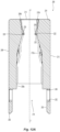
- FIG. 7 An alternative embodiment of a multi-fiber ferrule 100' is illustrated in Fig. 7 .
- the top portion 104' has two top cut-outs 130' that form two first forward facing surfaces 132'.
- the two top cut-outs 130' are separated by a continuation 104a' of the top portion 104'.
- the continuation 104a' of the top portion 104' acts as a key for the a multi-fiber ferrule 100'.
- the continuation 104a' may act as a polarity key or wedge.
- the continuation 104a' may be presented only partially separate the two top cutouts 130 '. Otherwise, the multi-fiber ferrule 100' is the same as noted above with regard to multi-fiber ferrule 100.
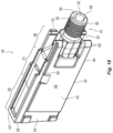
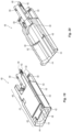
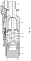
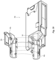
- a fiber optic ferrule receiver 200 to receive a fiber optic ferrule 100 according to the present invention.
- the fiber optic ferrule receiver 200 can be used in a number of different connectors and assemblies. As illustrated in Figs. 8 and 9 , the fiber optic ferrule receiver 200 is a part of a fiber optic connector 400. Additionally and as discussed in more detail below, the elements of the fiber optic ferrule receiver 200 may be found in other receivers as well. For example, the features of the fiber optic ferrule receiver 200 may be included in an adapter, into which the fiber optic ferrule 100 would be directly inserted.
- FIG. 10 the components of the fiber optic connector 400 will be described, moving in a front to rear direction (or left to right in the figure).
- the fiber optic ferrule receiver 200 is on the far left, with the multi-fiber ferrule 100 that will be inserted into the fiber optic ferrule receiver 200 next in line. While the multi-fiber ferrule 100 is illustrated, the invention may apply to other fiber optic ferrules as well.
- Behind the multi-fiber ferrule 100 is a guide pin keeper or spacer 402.
- a spring 404 (or other elastic element) is disposed in front end of a housing 406 (and is described in more detail below) to bias the multi-fiber ferrule 100 in a forward direction with the fiber optic ferrule receiver 200.
- a crimp ring 408 is used to secure the strength members associated with the optical fibers (not shown) to the housing 406.
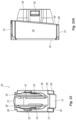
- a push-pull boot 410 is attached to the housing 406.
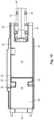
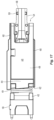
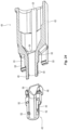
- the fiber optic ferrule receiver 200 includes a main body 202 extending between a front end 204 and a rear end 206. See Figs. 11 and 12 .
- the main body 202 has four sides 208,210,212,214, and an opening 216 extending between the front end 204 and the rear end 206 and being defined at least by a portion of internal surfaces of the four sides 208,210,212,214.
- the first side 208 and the second side 210 are on opposite sides of the opening 216, while the third side 212 and the fourth side 214 are each connected to the first side 208 and the second side 210 and are opposite each other about the opening 216.
- the third side 212 and the fourth side 214 have internal surfaces that are preferably flat and linear, but they may have tapering features like the internal surfaces of first side 208 and second side 210, discussed in detail below.
- the third side 212 may include a polarity step or a polarity mark to indicate orientation of the fiber optic ferrule receiver 200 and hence, the fiber optic ferrule 100. See also Fig. 13 .
- the first side 208 has a first tapered surface 208a in the opening 216 as well as a second tapered surface 208b, the first tapered surface 208a reducing the opening 216 between the rear end 206 and a first position 220, and the second tapered surface 208b increasing the opening 216 between the first position 220 and the front end 204.
- the first tapered surface 208a may have a number of ramped and flat portions. The first tapered surface 208a is to prevent the front end 114 of the main body 102 of the multi-fiber ferrule 100 from encountering any surface that causes damage to the front end 114 or causes the multi-fiber ferrule 100 from catching as it is inserted into the opening 216.
- the second side 210 also has a third tapered surface 210a in the opening 216 as well as a fourth tapered surface 210b, the third tapered surface 210a reducing the opening 216 between the rear end 206 and a second position 222, and the fourth tapered surface 210b increasing the opening 216 between the second position 222 and the front end 204.
- the first position 220 and the second position 222 are directly across the opening 216 from each other.
- the first position 220 and the second position 222 may be off set from one another along a longitudinal axis F through the fiber optic ferrule receiver 200.
- the first portion 220 and the second portion 222 can be thought of as a line that extends across the opening 416 between the third side 212 and the fourth side 214 and on the first side 208 and the second side 210, respectively.
- the first position 220 and/or the second position 222 may be a flat surface, e.g., parallel to the first side 208 and the second side 210. That is, there may be a flat surface formed at a junction of the first tapered surface 208a and the second tapered surface 208b. Likewise, there may be another flat surface formed at a junction of the third tapered surface 210a and the fourth tapered surface 210b.
- the fiber optic ferrule receiver 200 has a first projection 230 extending into the opening 216 from the first side 208 to engage the multi-fiber ferrule 100 at the first position 220.
- the first projection 230 engages the first forward facing surface 132 of the multi-fiber ferrule 100.
- the first projection 230 could engage any appropriate structure on the multi-fiber ferrule 100.
- the projection 230 preferably has a rearward facing surface 232 to engage the first forward facing surface 132 of the multi-fiber ferrule 100.
- the first projection 230 extends across the opening 216 in the appropriate location and width for that engagement.
- the first projection 230 preferably has a ramp surface 234 that extends from the first position 220 towards the front end 204.
- the ramp surface 234 extends all of the way to the front end 204, it could stop short thereof.
- the first projection 230 may have other configurations, such as a flat plateau like profile, instead of a ramp to engage the multi-fiber ferrule 100.
- the ferrule receiver 200 has a second projection 240 extending into the opening 216 from the second side 210 to engage the multi-fiber ferrule 100 at the second position 222.
- the second projection 240 engages the second forward facing surface 152 of the multi-fiber ferrule 100.
- the second projection 240 could engage any appropriate structure on the multi-fiber ferrule 100.
- the second projection 240 preferably has a rearward facing surface 242 to engage the second forward facing surface 152 of the multi-fiber ferrule 100.
- the second projection 240 extends across the opening 216 in the appropriate location and width for that engagement with the fiber optic ferrule receiver 200. As is clear in Fig.
- first projection 230 and the second projection 240 particularly with the ramp surfaces 234,244 cause the second and fourth tapered surfaces 208b,210b to be split into two sections - one on each side of the projections 230, 240. See Fig 13 .
- first tapered surface 208a and the second tapered surface 208b, as well as the third tapered surface 210a and the fourth tapered surface 210b are connected to one another about the first position 220 and second position 222, respectively.
- Such a connection may be along a line or along a flat plane.
- the rear end 206 of the main body 202 is not orthogonal to the longitudinal axis F extending through the main body 202. See, e.g., Fig. 11 . Rather, it has an angle that matches the angle at the front of the housing 406. One will be able to discern from this angled surface, where the first projection 230 and the second projection 240 are within the main body 202. This will allow for the multi-fiber ferrule 100 to be inserted so that the first projection 230 and the second projection 240 engage correct ones of the forward facing surfaces 132, 152 in the multi-fiber ferrule 100. See, e.g., Figs. 12 and 15 .
- the tabs 250 Extending from the rear end 206, and away from the main body 202, are two tabs 250, one is mounted on side 208 and the other on side 210.
- the two tabs 250 each have a shape of the letter "T".
- the tabs 250 have cut-outs 252 which form legs 254.
- the tabs 250 and the legs 254 are able to flex outward from the opening 216 and engage the housing 406 as described below. See also Figs. 15 and 16 .
- the tabs 250 have a rear surface 256 that is perpendicular to the longitudinal axis F.
- the cut-outs 252 between the tab 205 and the legs 254 are not rectangular, but are trapezoidal, allowing the rear end 206 to be angled, while still having the rear surface 256 and the front end 204 perpendicular to the longitudinal axis F.
- the main body 202 of the fiber optic ferrule receiver 200 has a plurality of shoulders 260 that extending from the front end 204 to the rear end 206.
- the shoulders are generally at the corners of the main body 202, where the sides 208,210, 212,214 meet. These shoulders 260 act as a guide to align the fiber optic connector 400 with another receptacle, such as an adapter.
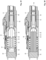
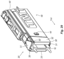
- the housing 406 will now be described with reference to Figs. 18-28 .
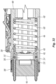
- the housing 406 has a main body 420 that extends between a front end 422 and a rear end 424 and generally has three sections.
- the housing 406 also has an opening 426 that extends between the front end 422 and the rear end 424.
- the first section 428 is a front section that receives an elastic member such as spring 404.
- the elastic member or spring 404 is to engage, directly or indirectly, the rear end of the multi-fiber ferrule 100 and bias it in a forward direction.
- the spring 404 engages forward facing surfaces 430 that extend into the opening 426 from the interior surface 432 and function as an integral spring stop. Referring to Fig.
- FIG. 20 in the cross-section, two of the forward facing surfaces 430 are illustrated, each continuing around one side of the housing 406 internally (see also Fig. 21 ) on the other half of the main body 420 that is not visible.
- the front end 422 has a chamfered surface 434 that assists in inserting the spring 404 during the initial insertion as well as movement of the spring 404 during use of the housing 406 in the fiber optic connector 400.
- the opening 426 is illustrated as being oval in cross section, but it could have other configurations as needed (e.g., an elliptical configuration).
- the spring 404 is accordingly shaped to be received inside the opening 426, and engage and seat at the forward facing surfaces 430.
- depressions 444 are also at the front end 422 and on first side 440 and on opposing second side 442 to receive the tab 250 and legs 254 from the fiber optic ferrule receiver 200 to removably secure the fiber optic ferrule receiver 200 to the main body 420. See, Fig. 19 and Fig. 21 showing a front view of the housing 406.
- the main body 420 of the housing 406 has a plurality of shoulders 460 that extending from the front end 422 to the rear end 424.
- the shoulders are generally at the corners of the main body 420, where first side 440 meets with top side 462 and bottom side 464 and second side 442 meets with top side 462 and bottom side 464.
- These shoulders 460 act as a guide to align the fiber optic connector 400 with another receptacle, such as an adapter.
- the shoulders 460 also match with the shoulders 260 on the fiber optic ferrule receiver 200 to form a continuous shoulder at each corner.
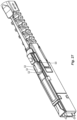
- the third or rear section 480 is used to finalize the configuration of the optical fibers 300 from the transition area in the middle section 470 to the cable format.
- the rear section 480 has an outer surface 482 to engage the crimp ring 408.
- the outer surface 482 is on a circular extension or crimp body 486 that extends from the rear end 424.
- the crimp body 486 is preferably made from two portions, a first portion 490 that is integral with the main body 420 and a second portion 492 that is removable from the main body 420 and the first portion 490. See Figs. 19-20 and 23-24 .
- the second portion 492 has a rear section 494 that is a half cylinder and a forward section 496 that mates with the main body 420 to close the middle section 470.
- the rear portion 494 mates with the first portion 490 to form the cylindrical shape that can accept the crimp ring 408.
- the rear section 494 mates with the first portion 490 with a series of projections 500 and recesses 502. As illustrated in the figures, the projections 500 are on the first portion 490 and the recesses 502 are on the second portion 492. However, the projections and recesses could be reversed or mixed with regard to their positions on the first portion 490 and the second portion 492.
- the projections 500 preferably frictionally engage the recesses 502 and then once the crimp ring 408 is secured around the crimp body 486, the two portions 490,492 will not move relative to one another.
- the forward section 496 of the second portion 492 mates with the main body 420 of the housing 406.
- the main body 420 has an extra portion 504 that has been cut out to allow for more optical fibers and larger groups of optical fibers to pass through the opening 426. This makes the opening 426 at the forward section 496 larger than on the opposing side..
- the larger opening 426 allows the housing 406 to be installed onto the cable and slid down the cable and out of the way during termination and polishing of the ferrule 100. That is when viewed straight into the opening 426 from the rear section 494, or even from the front end 422, the opening 426 is asymmetrical due to the presence of the first portion 490 and the extra portion 504. See Figs. 22 , 23 .
- the forward section 496 of the crimp body 486 has a tab 506 that extends into the extra portion 504 to close it off when the two portions 490,492 are mated.
- the housing 406 also has a number of latches 520 that extend from the main body 420 to engage a push-pull boot 410 and more specifically two latches 522 on the push-pull boot. See Figs. 9 , 10 , 24 , and 27 . As illustrated, the latches 522 on the push-pull boot can slide in the area 524 between two latches 520 on each side of the housing 406. See Fig. 27 . When the push-pull boot 410 is pulled, the latches 522 slide within the area 524 until they reach the end of the latches 520 and at this point, the force is transferred to the latches 520 and the housing 406 to remove the fiber optic connector from its receiver.
- the push-pull boot 410 is pushed until the latches 522 engage the front end of the area 524, which then transfers to the housing 406 and moves the fiber optic connector in a forward direction to secure it within a receptacle.
- FIG. 39 there is a housing 406a that has a second portion 492a of a crimp body 486a and a latch 520a molded thereon.
- the housing 406a has the same components as the housing discussed above, as well as the extra portion 504' that has been cut out to allow for more optical fibers and larger groups of optical fibers to be used with this housing 406a.
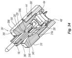
- FIGs. 29-34 Another embodiment of a housing 406' and a fiber optic ferrule receiver 200' according to the present invention are illustrated in Figs. 29-34 .
- the fiber optic ferrule that is used in these figures corresponds to multi-fiber ferrule 100 discussed above, but another fiber optic ferrule could also be used.
- This embodiment of a fiber optic ferrule receiver 200' includes a main body 202' extending between a front end 204' and a rear end 206'.
- the main body 202' also has four sides 208',210',212',214', and an opening 216' extending between the front end 204' and the rear end 206' and being defined at least by a portion of internal surfaces of the four sides 208',210',212',214'.
- the fiber optic ferrule receiver 200' also includes two tabs 250' that extend rearwardly from the rear end 206'.
- the two tabs 250' each have a projection 252' that extend outwardly and away from each other.
- the projections 252' are designed to engage an opening 444' on each side of the housing 406', as described in more detail below.
- the two tabs 250' are somewhat flexible in that they can flex inward to be inserted into the housing 406' and subsequently return, at least partially, to their pre-flexed configuration. This allows the fiber optic ferrule receiver 200' to be retained in the housing 406'.
- the length of fiber optic ferrule receiver 200' (the distance between the front end 204' and the rear end 206 ') is shorter than that of fiber optic ferrule receiver 200.
- the housing 406' is therefore longer so that the combination of the housing 406' and the fiber optic ferrule receiver 200' are preferably the same overall length. It is also clear from Fig. 33A that the rear end 206' of the a fiber optic ferrule receiver 200' and the front end of the housing 406' are slanted as in the previous embodiment for the purposes of polarity.
- the opening 216' of the fiber optic ferrule receiver 200' has the same general configuration of a fiber optic ferrule receiver 200. That is, first side 208' and second side 210' are on opposite sides of the opening 216', while third side 212' and fourth side 214' are each connected to the first side 208' and the second side 210' and are opposite each other about the opening 216'. Third side 212' and fourth side 214' have internal surfaces that are preferably flat and linear, but they may have tapering features discussed above.
- First side 208' has a first tapered surface 208a' in the opening 216' as well as a second tapered surface 208b', the first tapered surface 208a' reducing the opening 216' between the rear end 206' and a first position 220', and the second tapered surface 208b' increasing the opening 216' between the first position 220' and the front end 204'. See Fig. 34 .
- the first tapered surface 208a' may have a number of ramped and flat portions.
- the first tapered surface 208a' is to prevent the front end 114 of the main body 102 of the multi-fiber ferrule 100 from encountering any surface that causes damage to the front end 114 or causes the multi-fiber ferrule 100 from catching as it is inserted into the opening 216'.
- Second side 210' also has a third tapered surface 210a' in the opening 216' as well as a fourth tapered surface 210b', the third tapered surface 210a' reducing the opening 216' between the rear end 206' and a second position 222', and the fourth tapered surface 210b' increasing the opening 216' between the second position 222' and the front end 204'.
- the first position 220' and the second position 222' are directly across the opening 216' from each other.
- the first position 220' and the second position 222' may be off set from one another.
- the front section 602 has a second side 616 that has a third tapered surface 616a in the opening 608 as well as a fourth tapered surface 616b.
- the third tapered surface 616a reduces the opening 608 between the rear end 606 and a second position 618, and the fourth tapered surface 616b increasing the opening 608 between the second position 618. and the front end 604.
Landscapes
- Physics & Mathematics (AREA)
- General Physics & Mathematics (AREA)
- Optics & Photonics (AREA)
- Mechanical Coupling Of Light Guides (AREA)
- Optical Couplings Of Light Guides (AREA)
- Connector Housings Or Holding Contact Members (AREA)
Claims (14)
- Récepteur de ferrule de fibres optiques (200) d'un connecteur de fibres optiques (400) destiné à recevoir dans celui-ci une ferrule de fibres optiques (100) du connecteur de fibres optiques (400), le récepteur (200) comprenant :un corps principal (202) s'étendant entre une extrémité avant (204) et une extrémité arrière (206) et présentant quatre côtés (208, 210, 212, 214), le corps principal présentant une ouverture (216) s'étendant entre l'extrémité avant et l'extrémité arrière et étant définie au moins par une partie des surfaces internes des quatre côtés ;un premier côté (208) dans l'ouverture présentant une première surface conique (208a) et une deuxième surface conique (208b), la première surface conique réduisant l'ouverture entre l'extrémité arrière et une première position et la deuxième surface conique augmentant l'ouverture entre la première position et l'extrémité avant ;un deuxième côté (210) dans l'ouverture et en travers de l'ouverture par rapport au premier côté, le deuxième côté présentant une troisième surface conique (210a) et une quatrième surface conique (210b), la troisième surface conique réduisant l'ouverture entre l'extrémité arrière et une deuxième position et la quatrième surface conique augmentant l'ouverture entre la deuxième position et l'extrémité avant ;une première saillie (230) s'étendant dans l'ouverture depuis le premier côté pour venir en prise avec une première partie de la ferrule de fibres optiques au niveau de la première position ; etune seconde saillie (240) s'étendant dans l'ouverture depuis le deuxième côté pour venir en prise avec une deuxième partie de la ferrule de fibres optiques au niveau de la deuxième position,caractérisé en ce quele récepteur de ferrule de fibres optiques (200) comprend en outre au moins une languette (250) s'étendant depuis l'extrémité arrière (206), la languette présentant des échancrures opposées (252) pour former des pattes (254) qui peuvent fléchir vers l'extérieur depuis l'ouverture (216) pour venir en prise avec un boîtier (406) pour le connecteur de fibres optiques (400).
- Récepteur de ferrule de fibres optiques selon la revendication 1, dans lequel l'extrémité arrière (206) présente une surface arrière, la surface arrière étant non perpendiculaire à un axe longitudinal F s'étendant à travers l'ouverture (216) depuis l'extrémité avant (204) jusqu'à l'extrémité arrière.
- Récepteur de ferrule de fibres optiques selon la revendication 1, dans lequel une configuration de l'extrémité arrière (206) du corps principal (202) correspond à l'emplacement de la première saillie (230) et de la seconde saillie (240) dans l'ouverture (216) du récepteur de ferrule de fibres optiques.
- Récepteur de ferrule de fibres optiques selon la revendication 1, dans lequel la languette (250) présente une configuration globalement en forme de « T ».
- Récepteur de ferrule de fibres optiques selon la revendication 1, dans lequel la languette (250) présente une partie la plus en arrière, la partie la plus en arrière présentant une surface (256) qui est perpendiculaire à un axe longitudinal F s'étendant à travers l'ouverture (216) depuis l'extrémité avant (204) jusqu'à l'extrémité arrière (206).
- Récepteur de ferrule de fibres optiques selon la revendication 1, dans lequel le corps principal (202) présente une marque de polarité sur l'un des côtés (212).
- Récepteur de ferrule de fibres optiques selon la revendication 1, dans lequel le corps principal (202) présente une pluralité d'épaulements (260) s'étendant depuis l'extrémité avant (204) jusqu'à l'extrémité arrière (206) pour aligner le récepteur de ferrule de fibres optiques (200) avec un adaptateur.
- Récepteur de ferrule de fibres optiques selon la revendication 7, dans lequel chacun de la pluralité d'épaulements (260) est disposé à une jonction de deux des côtés (208, 210, 212, 214).
- Récepteur de ferrule de fibres optiques selon la revendication 1, dans lequel chacune de la première saillie (230) et de la seconde saillie (240) présente une longueur, la longueur de la première saillie étant supérieure à celle de la seconde saillie.
- Récepteur de ferrule de fibres optiques selon la revendication 1, dans lequel la première saillie (230) et la seconde saillie (240) confèrent une fonction de clavetage à la ferrule de fibres optiques (100).
- Récepteur de ferrule de fibres optiques selon la revendication 1, dans lequel les première et deuxième surfaces coniques (208a, 208b) sur le premier côté (208) et le deuxième côté (210) sont reliées l'une à l'autre en travers d'au moins une partie de l'ouverture (216).
- Récepteur de ferrule de fibres optiques selon la revendication 11, dans lequel la deuxième surface conique (208b) du premier côté (208) comprend deux deuxièmes surfaces coniques et la première saillie (230) est disposée entre les deux deuxièmes surfaces coniques.
- Récepteur de ferrule de fibres optiques selon la revendication 11, dans lequel la quatrième surface conique du deuxième côté (210) comprend deux quatrièmes surfaces coniques (210b) et la seconde saillie (240) est disposée entre les deux quatrièmes surfaces coniques.
- Récepteur de ferrule de fibres optiques selon la revendication 1, dans lequel chacune de la première saillie (230) et de la seconde saillie (240) s'étendent plus loin dans l'ouverture (216) qu'une quelconque surface parmi la première surface conique (208a), la deuxième surface conique (208b), la troisième surface conique (210a) et la quatrième surface conique (210b).
Priority Applications (1)
| Application Number | Priority Date | Filing Date | Title |
|---|---|---|---|
| EP25176345.4A EP4579300A3 (fr) | 2020-04-23 | 2021-04-23 | Ferrule de fibres optiques et systèmes de ferrule de fibres optiques |
Applications Claiming Priority (3)
| Application Number | Priority Date | Filing Date | Title |
|---|---|---|---|
| US202063014491P | 2020-04-23 | 2020-04-23 | |
| US202063047657P | 2020-07-02 | 2020-07-02 | |
| PCT/US2021/028925 WO2021217054A1 (fr) | 2020-04-23 | 2021-04-23 | Ferrule de fibres optiques et systèmes de ferrule de fibres optiques |
Related Child Applications (2)
| Application Number | Title | Priority Date | Filing Date |
|---|---|---|---|
| EP25176345.4A Division-Into EP4579300A3 (fr) | 2020-04-23 | 2021-04-23 | Ferrule de fibres optiques et systèmes de ferrule de fibres optiques |
| EP25176345.4A Division EP4579300A3 (fr) | 2020-04-23 | 2021-04-23 | Ferrule de fibres optiques et systèmes de ferrule de fibres optiques |
Publications (2)
| Publication Number | Publication Date |
|---|---|
| EP4139726A1 EP4139726A1 (fr) | 2023-03-01 |
| EP4139726B1 true EP4139726B1 (fr) | 2025-06-25 |
Family
ID=75914599
Family Applications (6)
| Application Number | Title | Priority Date | Filing Date |
|---|---|---|---|
| EP21725887.0A Active EP4139727B1 (fr) | 2020-04-23 | 2021-04-23 | Boîtier pour connecteur de fibres optiques |
| EP21725885.4A Active EP4139726B1 (fr) | 2020-04-23 | 2021-04-23 | Ferrule de fibres optiques et systèmes de ferrule de fibres optiques |
| EP25166348.0A Pending EP4553550A3 (fr) | 2020-04-23 | 2021-04-23 | Ferrule multifibre miniature |
| EP24217512.3A Pending EP4495648A3 (fr) | 2020-04-23 | 2021-04-23 | Boîtier pour connecteur de fibres optiques |
| EP25176345.4A Pending EP4579300A3 (fr) | 2020-04-23 | 2021-04-23 | Ferrule de fibres optiques et systèmes de ferrule de fibres optiques |
| EP21725638.7A Active EP4139725B1 (fr) | 2020-04-23 | 2021-04-23 | Ferrule multifibre miniature |
Family Applications Before (1)
| Application Number | Title | Priority Date | Filing Date |
|---|---|---|---|
| EP21725887.0A Active EP4139727B1 (fr) | 2020-04-23 | 2021-04-23 | Boîtier pour connecteur de fibres optiques |
Family Applications After (4)
| Application Number | Title | Priority Date | Filing Date |
|---|---|---|---|
| EP25166348.0A Pending EP4553550A3 (fr) | 2020-04-23 | 2021-04-23 | Ferrule multifibre miniature |
| EP24217512.3A Pending EP4495648A3 (fr) | 2020-04-23 | 2021-04-23 | Boîtier pour connecteur de fibres optiques |
| EP25176345.4A Pending EP4579300A3 (fr) | 2020-04-23 | 2021-04-23 | Ferrule de fibres optiques et systèmes de ferrule de fibres optiques |
| EP21725638.7A Active EP4139725B1 (fr) | 2020-04-23 | 2021-04-23 | Ferrule multifibre miniature |
Country Status (4)
| Country | Link |
|---|---|
| US (7) | US12019278B2 (fr) |
| EP (6) | EP4139727B1 (fr) |
| CN (3) | CN115516355A (fr) |
| WO (3) | WO2021217057A1 (fr) |
Families Citing this family (22)
| Publication number | Priority date | Publication date | Assignee | Title |
|---|---|---|---|---|
| EP3729153B1 (fr) * | 2017-12-19 | 2024-07-10 | US Conec, Ltd | Mini-connecteur duplex avec mécanisme de polarité poussée-traction et support |
| US12321017B2 (en) | 2020-04-23 | 2025-06-03 | Us Conec Ltd. | Fiber optic ferrule and fiber optic ferrule receiver |
| EP4139727B1 (fr) | 2020-04-23 | 2025-07-23 | US Conec, Ltd | Boîtier pour connecteur de fibres optiques |
| US11650379B2 (en) | 2020-10-14 | 2023-05-16 | Us Conec Ltd. | Anti-buckling latch for a fiber optic connector |
| EP4314917A1 (fr) | 2021-04-02 | 2024-02-07 | US Conec, Ltd | Support de ferrule pour ferrule mt miniature et interface d'adaptateur pour accouplement avec des connecteurs de fibres optiques |
| US12523821B2 (en) | 2021-04-08 | 2026-01-13 | Commscope Technologies Llc | Telecommunications connector with latch release mechanism |
| US12078854B2 (en) | 2021-04-23 | 2024-09-03 | US Conec, Ltd | Optical assembly |
| US12130480B2 (en) | 2021-05-17 | 2024-10-29 | Us Conec Ltd. | Polarity scheme for multi-fiber connectors with a connector key |
| EP4409343A4 (fr) * | 2021-09-30 | 2025-10-22 | Senko Advanced Components Inc | Systèmes de réseaux à fibres optiques |
| US12366711B2 (en) | 2021-12-08 | 2025-07-22 | Us Conec Ltd. | Small form factor fiber optic connector dust cap |
| WO2023122215A1 (fr) | 2021-12-22 | 2023-06-29 | US Conec, Ltd | Connecteur de fibre optique présentant un avantage mecanique |
| US12422627B2 (en) | 2022-05-02 | 2025-09-23 | Us Conec Ltd. | Data center interconnect for optical trunk cables having miniature multi-fiber ferrules |
| US12546954B2 (en) | 2022-05-31 | 2026-02-10 | Us Conec Ltd. | Fiber cable jacket retention features for VSFF fiber-optic connectors |
| US20250370195A1 (en) | 2022-07-20 | 2025-12-04 | Us Conec Ltd. | Mpo connector with non-mt multi-fiber ferrule and sleeve therefor |
| WO2024044060A1 (fr) | 2022-08-22 | 2024-02-29 | Corning Research & Development Corporation | Ferrule multifibre à transition conique en perçage de ferrule |
| US20240085636A1 (en) | 2022-09-13 | 2024-03-14 | Us Conec Ltd. | Optical Assembly with Adapter for Intermating Different Multi-Fiber Ferrule Formats within the Adapter |
| WO2024247936A1 (fr) * | 2023-05-31 | 2024-12-05 | 株式会社フジクラ | Connecteur optique à âmes multiples |
| USD1094314S1 (en) * | 2023-07-14 | 2025-09-23 | Senko Advanced Components, Inc. | MT ferrule |
| USD1102389S1 (en) * | 2023-10-26 | 2025-11-18 | Hakusan Inc. | Optical connector |
| WO2025126615A1 (fr) * | 2023-12-15 | 2025-06-19 | 株式会社フジクラ | Connecteur optique |
| WO2025175183A1 (fr) | 2024-02-14 | 2025-08-21 | Us Conec Ltd. | Insertion de masse de fibres optiques sur un dispositif de zone active |
| WO2025222088A1 (fr) | 2024-04-18 | 2025-10-23 | Us Conec Ltd. | Ferrules à lentilles pour connecteurs optiques compacts |
Family Cites Families (72)
| Publication number | Priority date | Publication date | Assignee | Title |
|---|---|---|---|---|
| US4178068A (en) * | 1977-11-14 | 1979-12-11 | Amp Incorporated | Fiber optic cable termination means |
| US4762389A (en) * | 1984-03-30 | 1988-08-09 | Nec Corporation | Optical fiber connector |
| US5016970A (en) * | 1989-08-22 | 1991-05-21 | Nippon Telegraph And Telephone Corp. | Ferrule for optical fiber transmitting linearly polarized light and optical fiber connector using this ferrule |
| US5746764A (en) * | 1995-12-04 | 1998-05-05 | Atrion Medical Products, Inc. | Stent compression instrument |
| JP3571863B2 (ja) * | 1996-10-16 | 2004-09-29 | 古河電気工業株式会社 | 光コネクタの光ファイバ突出長設定方法およびその治具 |
| JP3370908B2 (ja) * | 1997-08-18 | 2003-01-27 | 株式会社フジクラ | 光コネクタ |
| JPH11109161A (ja) | 1997-09-30 | 1999-04-23 | Sumitomo Electric Ind Ltd | 光ファイバアレイ、フェルール及びこのフェルールを利用した光コネクタ |
| US6154597A (en) | 1998-01-05 | 2000-11-28 | Molex Incorporated | Fiber optic termination system including a fiber optic connector assembly and method of fabricating same |
| US6435730B1 (en) * | 1998-05-06 | 2002-08-20 | The Whitaker Corporation | Optical fiber connector with improved ferrule float feature |
| US6085003A (en) * | 1998-07-28 | 2000-07-04 | Us Conec Ltd | Multifiber connector having a free floating ferrule |
| US6106162A (en) * | 1998-11-12 | 2000-08-22 | Delphi Technologies Inc. | Glass optical fiber bundle connector for a hybrid fiber optic lighting distribution system |
| US6195477B1 (en) * | 1998-11-12 | 2001-02-27 | Delphi Technologies, Inc. | Hybrid fiber optic lighting distribution system |
| EP1039323A1 (fr) * | 1999-03-23 | 2000-09-27 | W.L. GORE & ASSOCIATES | Embout pour fibres optiques |
| US6357933B1 (en) * | 1999-03-30 | 2002-03-19 | Lucent Technologies Inc. | Quick connect optical fiber ferrule connector |
| US6547449B1 (en) | 1999-12-17 | 2003-04-15 | Corning Cable Systems Llc | Windowless, rectangular ferrule in a preassembled multifiber connector and associated assembly method |
| US6412988B1 (en) | 1999-12-30 | 2002-07-02 | Corning Cable Systems Llc | Ferrule and fiber optic connector housing having enlarged shoulders |
| JP3917378B2 (ja) * | 2001-01-17 | 2007-05-23 | 株式会社オートネットワーク技術研究所 | 光ファイバ端末処理方法及び光ファイバ端末処理装置 |
| US6422760B1 (en) * | 2001-01-31 | 2002-07-23 | Molex Incorporated | Fiber optic connector module |
| US6663293B2 (en) * | 2001-03-16 | 2003-12-16 | Fitel Usa Corp. | Tunable optical fiber connector |
| JP2002318324A (ja) * | 2001-04-20 | 2002-10-31 | Furukawa Electric Co Ltd:The | 光コネクタフェルール用ハウジング、ハウジング付き光コネクタフェルール、光コネクタ |
| US7036993B2 (en) | 2001-06-11 | 2006-05-02 | Corning Cable Systems Llc | Pin retainer for fiber optic connector and associated fabrication method |
| US6893165B2 (en) * | 2002-03-01 | 2005-05-17 | Fci Americas Technology, Inc. | Optic fiber connectors and coupling sleeve |
| US6705765B2 (en) * | 2002-05-20 | 2004-03-16 | Fitel Usa Corp. | Polarization maintaining optical fiber connector plug |
| US6957920B2 (en) * | 2002-06-24 | 2005-10-25 | Corning Cable Systems Llc | Ferrule assembly having highly protruding optical fibers and an associated fabrication method |
| JP2004038005A (ja) * | 2002-07-05 | 2004-02-05 | Akutowan:Kk | フェルール及びフェルールの製造方法 |
| US7393142B2 (en) * | 2003-08-29 | 2008-07-01 | Corning Cable Systems Llc | Molded ferrule with reference surface for end face geometry measurement |
| US20050036742A1 (en) * | 2003-08-29 | 2005-02-17 | Dean David L. | Molded fiber optic ferrule with integrally formed geometry features |
| US7785019B2 (en) * | 2005-03-10 | 2010-08-31 | Corning Cable Systems Llc | Multi-fiber fiber optic receptacle and plug assembly |
| US8104973B2 (en) | 2007-02-09 | 2012-01-31 | Us Conec, Ltd. | Ferrule-to-ferrule adapter and ferrule adapter assembly |
| US7540666B2 (en) | 2007-02-27 | 2009-06-02 | Corning Cable Systems Llc | Articulated force application for multi-fiber ferrules |
| US20090041412A1 (en) | 2007-08-07 | 2009-02-12 | Jeffrey Dean Danley | Laser erosion processes for fiber optic ferrules |
| US8109679B2 (en) * | 2008-11-25 | 2012-02-07 | Corning Cable Systems Llc | Optical ferrule assemblies and methods of making the same |
| US7841778B2 (en) | 2008-12-19 | 2010-11-30 | The Furukawa Electric Co., Ltd. | Optical connector |
| US8337093B2 (en) * | 2009-09-30 | 2012-12-25 | Corning Cable Systems Llc | Fiber optic connectors and methods for making the same |
| CN102346279B (zh) * | 2010-07-30 | 2015-03-11 | 株式会社藤仓 | 光连接器、连接器连接系统 |
| WO2012064594A1 (fr) | 2010-11-09 | 2012-05-18 | Corning Cable Systems Llc | Ferrules possédant des trajets optiques et connecteurs de fibre optique les utilisant |
| TWM450737U (zh) * | 2011-06-14 | 2013-04-11 | Molex Inc | 光纖組件 |
| US8540435B2 (en) * | 2011-07-22 | 2013-09-24 | Corning Cable Systems Llc | Ferrule retainers having access window(s) for accessing and/or referencing a fiber optic ferrule, and related fiber optic connector assemblies, connectors, and referencing methods |
| EP2756344A2 (fr) * | 2011-09-13 | 2014-07-23 | Corning Cable Systems LLC | Ensembles support de lentilles à translation utilisant des zones de relief d'alésage, et connecteurs optiques les intégrant |
| US8534928B2 (en) * | 2011-11-28 | 2013-09-17 | Corning Cable Systems Llc | Optical fiber assemblies, optical fiber organizers and methods of fabricating optical fiber assemblies |
| US9529155B2 (en) * | 2012-11-28 | 2016-12-27 | Corning Optical Communications LLC | Gradient index (GRIN) lens chips and associated small form factor optical arrays for optical connections, related fiber optic connectors |
| US9551841B2 (en) * | 2012-11-30 | 2017-01-24 | Corning Optical Communications LLC | Optical data center connector systems, fiber optic plug assemblies, and fiber optic receptacle assemblies |
| US9028154B2 (en) * | 2013-02-01 | 2015-05-12 | Avago Technologies General Ip (Singapore) Pte. Ltd. | Adapter for cleaning an optical junction and reducing optical back reflection |
| WO2014123873A1 (fr) * | 2013-02-05 | 2014-08-14 | Commscope, Inc. Of North Carolina | Procédés d'installation de câbles à fibre optique à plusieurs cœurs dans des connecteurs, et appareil connexe |
| US10495824B2 (en) * | 2014-05-16 | 2019-12-03 | Joel C. Rosson | Optical connector element |
| FR3021415A1 (fr) | 2014-05-21 | 2015-11-27 | Radiall Sa | Ferule de dimensions reduites pour contact optique, connecteur multi-contacts integrant une pluralite de telles ferules. |
| CN208140982U (zh) | 2014-10-03 | 2018-11-23 | 康宁光电通信有限责任公司 | 用于光纤连接器的套圈组件、光纤连接器及光纤电缆组件 |
| WO2016072330A1 (fr) | 2014-11-07 | 2016-05-12 | Seiオプティフロンティア株式会社 | Connecteur optique, élément de retenue de broches, poussoir de broche, élément d'expansion et outil poussoir de broche |
| US9568689B2 (en) * | 2015-02-18 | 2017-02-14 | US Conec, Ltd | Spring push and push-pull tab for tightly spaced fiber optic connectors |
| US10197743B2 (en) * | 2015-05-22 | 2019-02-05 | US Conec, Ltd | Multi-fiber ferrule with improved eye safety |
| EP4403972A3 (fr) * | 2015-11-30 | 2024-10-16 | CommScope Technologies LLC | Connecteur de fibre optique et son assemblage |
| US10191227B2 (en) * | 2016-01-20 | 2019-01-29 | Alliance Fiber Optics Products, Inc. | Fiber optic connector with small profile, and cable assemblies, systems, and methods including the same |
| US10156683B2 (en) * | 2016-04-11 | 2018-12-18 | Leviton Manufacturing Co., Inc. | Polarity identification for polarity reversing duplex unibody connectors |
| TWI608262B (zh) * | 2016-11-30 | 2017-12-11 | 林雨晴 | 光纖連接器 |
| WO2018116855A1 (fr) | 2016-12-19 | 2018-06-28 | 株式会社フジクラ | Virole, virole avec fibre optique et procédé de fabrication de virole avec fibre optique |
| US10451830B2 (en) * | 2016-12-29 | 2019-10-22 | Corning Optical Communications LLC | Fiber optic cable assembly and fabrication method using sequentially arranged boots for multi-fiber ferrule |
| US10725248B2 (en) * | 2017-01-30 | 2020-07-28 | Senko Advanced Components, Inc. | Fiber optic receptacle with integrated device therein incorporating a behind-the-wall fiber optic receptacle |
| US10185100B2 (en) | 2017-01-30 | 2019-01-22 | Senko Advanced Components, Inc | Modular connector and adapter assembly using a removable anchor device |
| US20190361177A1 (en) * | 2017-01-31 | 2019-11-28 | Sei Optifrontier Co., Ltd. | Optical connector and optical fiber with connector |
| EP3596520B1 (fr) * | 2017-03-16 | 2022-04-27 | Corning Research & Development Corporation | Ensembles de connecteurs optiques détachables et de puces optiques |
| US10281669B2 (en) | 2017-07-14 | 2019-05-07 | Senko Advance Components, Inc. | Ultra-small form factor optical connectors |
| JP6858108B2 (ja) | 2017-10-03 | 2021-04-14 | 株式会社フジクラ | 光コネクタ及びフェルール |
| US11002923B2 (en) * | 2017-11-21 | 2021-05-11 | Senko Advanced Components, Inc. | Fiber optic connector with cable boot release having a two-piece clip assembly |
| EP3729153B1 (fr) * | 2017-12-19 | 2024-07-10 | US Conec, Ltd | Mini-connecteur duplex avec mécanisme de polarité poussée-traction et support |
| EP4492108A3 (fr) | 2018-04-06 | 2025-04-09 | US Conec, Ltd | Tétine de poussée-traction flexible et corps de sertissage pour connecteur de fibre optique |
| US10948663B2 (en) | 2018-06-05 | 2021-03-16 | Panduit Corp. | Small form factor multi-fiber connector |
| JPWO2020149262A1 (ja) * | 2019-01-15 | 2021-11-25 | 住友電気工業株式会社 | 光コネクタおよび光接続構造 |
| US11340406B2 (en) * | 2019-04-19 | 2022-05-24 | Senko Advanced Components, Inc. | Small form factor fiber optic connector with resilient latching mechanism for securing within a hook-less receptacle |
| US11194107B2 (en) | 2019-08-20 | 2021-12-07 | Corning Incorporated | High-density FAUs and optical interconnection devices employing small diameter low attenuation optical fiber |
| US11353664B1 (en) | 2019-08-21 | 2022-06-07 | Senko Advanced Components, Inc. | Fiber optic connector |
| US11243361B2 (en) | 2019-12-18 | 2022-02-08 | Viavi Solutions France SAS | Mechanical transfer ferrule based optical switch |
| EP4139727B1 (fr) | 2020-04-23 | 2025-07-23 | US Conec, Ltd | Boîtier pour connecteur de fibres optiques |
-
2021
- 2021-04-23 EP EP21725887.0A patent/EP4139727B1/fr active Active
- 2021-04-23 WO PCT/US2021/028929 patent/WO2021217057A1/fr not_active Ceased
- 2021-04-23 EP EP21725885.4A patent/EP4139726B1/fr active Active
- 2021-04-23 EP EP25166348.0A patent/EP4553550A3/fr active Pending
- 2021-04-23 WO PCT/US2021/028925 patent/WO2021217054A1/fr not_active Ceased
- 2021-04-23 CN CN202180030131.2A patent/CN115516355A/zh active Pending
- 2021-04-23 CN CN202180028531.XA patent/CN115427857A/zh active Pending
- 2021-04-23 EP EP24217512.3A patent/EP4495648A3/fr active Pending
- 2021-04-23 US US17/908,430 patent/US12019278B2/en active Active
- 2021-04-23 EP EP25176345.4A patent/EP4579300A3/fr active Pending
- 2021-04-23 EP EP21725638.7A patent/EP4139725B1/fr active Active
- 2021-04-23 WO PCT/US2021/028919 patent/WO2021217050A1/fr not_active Ceased
- 2021-04-23 CN CN202180030573.7A patent/CN115461662A/zh active Pending
- 2021-04-23 US US17/918,058 patent/US11914195B2/en active Active
- 2021-04-23 US US17/918,067 patent/US12061362B2/en active Active
-
2024
- 2024-04-21 US US18/641,400 patent/US12379549B2/en active Active
- 2024-07-26 US US18/785,303 patent/US20240385387A1/en active Pending
-
2025
- 2025-05-01 US US19/196,010 patent/US20250258342A1/en active Pending
- 2025-07-07 US US19/261,655 patent/US20250334748A1/en active Pending
Also Published As
| Publication number | Publication date |
|---|---|
| EP4139726A1 (fr) | 2023-03-01 |
| EP4139727A1 (fr) | 2023-03-01 |
| CN115427857A (zh) | 2022-12-02 |
| US20250334748A1 (en) | 2025-10-30 |
| US12061362B2 (en) | 2024-08-13 |
| US11914195B2 (en) | 2024-02-27 |
| US12379549B2 (en) | 2025-08-05 |
| US20250258342A1 (en) | 2025-08-14 |
| EP4553550A3 (fr) | 2025-06-25 |
| WO2021217054A1 (fr) | 2021-10-28 |
| US20230161116A1 (en) | 2023-05-25 |
| EP4139725B1 (fr) | 2025-04-02 |
| EP4495648A2 (fr) | 2025-01-22 |
| EP4579300A3 (fr) | 2025-09-17 |
| US20240264383A1 (en) | 2024-08-08 |
| WO2021217050A1 (fr) | 2021-10-28 |
| EP4139725A1 (fr) | 2023-03-01 |
| EP4579300A2 (fr) | 2025-07-02 |
| WO2021217057A1 (fr) | 2021-10-28 |
| CN115461662A (zh) | 2022-12-09 |
| US20230091327A1 (en) | 2023-03-23 |
| US20230161115A1 (en) | 2023-05-25 |
| EP4139727B1 (fr) | 2025-07-23 |
| US20240385387A1 (en) | 2024-11-21 |
| EP4553550A2 (fr) | 2025-05-14 |
| EP4495648A3 (fr) | 2025-03-19 |
| US12019278B2 (en) | 2024-06-25 |
| CN115516355A (zh) | 2022-12-23 |
Similar Documents
| Publication | Publication Date | Title |
|---|---|---|
| EP4139726B1 (fr) | Ferrule de fibres optiques et systèmes de ferrule de fibres optiques | |
| EP3330758B1 (fr) | Connecteur de fibre optique | |
| US11592626B2 (en) | Fiber optic connector with boot-integrated release and related assemblies | |
| EP1122566B1 (fr) | Système de connexion pour fibre optique | |
| US5315679A (en) | Optical fibers duplex connector assembly | |
| CN100388028C (zh) | 连接器组件夹子 | |
| EP2588907B1 (fr) | Connecteur de type mpo possédant une charge hors centre réduite | |
| US20240085636A1 (en) | Optical Assembly with Adapter for Intermating Different Multi-Fiber Ferrule Formats within the Adapter | |
| KR20130004236U (ko) | 상보적인 짝맞춤 형상부를 갖는 페룰 및 관련 섬유 광학 컨넥터 | |
| EP4314918B1 (fr) | Support de ferrule pour ferrule mt miniature et interface d'adaptateur pour accouplement avec des connecteurs de fibre optique | |
| US12321017B2 (en) | Fiber optic ferrule and fiber optic ferrule receiver | |
| CN100468107C (zh) | 键固光纤连接器 | |
| WO2006029299A2 (fr) | Systeme de connexion optique comprenant une ferrule de type mt de taille reduite | |
| WO2022081547A1 (fr) | Système de connexion à fibres multiples | |
| KR20130002936U (ko) | 상보적인 짝맞춤 형상부를 갖는 페룰 및 관련 섬유 광학 컨넥터 | |
| WO2022178017A1 (fr) | Connecteurs de télécommunication à profil bas |
Legal Events
| Date | Code | Title | Description |
|---|---|---|---|
| STAA | Information on the status of an ep patent application or granted ep patent |
Free format text: STATUS: UNKNOWN |
|
| STAA | Information on the status of an ep patent application or granted ep patent |
Free format text: STATUS: THE INTERNATIONAL PUBLICATION HAS BEEN MADE |
|
| PUAI | Public reference made under article 153(3) epc to a published international application that has entered the european phase |
Free format text: ORIGINAL CODE: 0009012 |
|
| STAA | Information on the status of an ep patent application or granted ep patent |
Free format text: STATUS: REQUEST FOR EXAMINATION WAS MADE |
|
| 17P | Request for examination filed |
Effective date: 20221121 |
|
| AK | Designated contracting states |
Kind code of ref document: A1 Designated state(s): AL AT BE BG CH CY CZ DE DK EE ES FI FR GB GR HR HU IE IS IT LI LT LU LV MC MK MT NL NO PL PT RO RS SE SI SK SM TR |
|
| DAV | Request for validation of the european patent (deleted) | ||
| DAX | Request for extension of the european patent (deleted) | ||
| P01 | Opt-out of the competence of the unified patent court (upc) registered |
Free format text: CASE NUMBER: APP_37201/2024 Effective date: 20240621 |
|
| GRAP | Despatch of communication of intention to grant a patent |
Free format text: ORIGINAL CODE: EPIDOSNIGR1 |
|
| STAA | Information on the status of an ep patent application or granted ep patent |
Free format text: STATUS: GRANT OF PATENT IS INTENDED |
|
| INTG | Intention to grant announced |
Effective date: 20241029 |
|
| GRAJ | Information related to disapproval of communication of intention to grant by the applicant or resumption of examination proceedings by the epo deleted |
Free format text: ORIGINAL CODE: EPIDOSDIGR1 |
|
| STAA | Information on the status of an ep patent application or granted ep patent |
Free format text: STATUS: REQUEST FOR EXAMINATION WAS MADE |
|
| GRAS | Grant fee paid |
Free format text: ORIGINAL CODE: EPIDOSNIGR3 |
|
| INTC | Intention to grant announced (deleted) | ||
| STAA | Information on the status of an ep patent application or granted ep patent |
Free format text: STATUS: GRANT OF PATENT IS INTENDED |
|
| GRAP | Despatch of communication of intention to grant a patent |
Free format text: ORIGINAL CODE: EPIDOSNIGR1 |
|
| INTG | Intention to grant announced |
Effective date: 20250407 |
|
| GRAA | (expected) grant |
Free format text: ORIGINAL CODE: 0009210 |
|
| STAA | Information on the status of an ep patent application or granted ep patent |
Free format text: STATUS: THE PATENT HAS BEEN GRANTED |
|
| AK | Designated contracting states |
Kind code of ref document: B1 Designated state(s): AL AT BE BG CH CY CZ DE DK EE ES FI FR GB GR HR HU IE IS IT LI LT LU LV MC MK MT NL NO PL PT RO RS SE SI SK SM TR |
|
| REG | Reference to a national code |
Ref country code: GB Ref legal event code: FG4D |
|
| REG | Reference to a national code |
Ref country code: CH Ref legal event code: EP |
|
| REG | Reference to a national code |
Ref country code: CH Ref legal event code: EP |
|
| REG | Reference to a national code |
Ref country code: IE Ref legal event code: FG4D |
|
| REG | Reference to a national code |
Ref country code: DE Ref legal event code: R096 Ref document number: 602021032849 Country of ref document: DE |
|
| PG25 | Lapsed in a contracting state [announced via postgrant information from national office to epo] |
Ref country code: FI Free format text: LAPSE BECAUSE OF FAILURE TO SUBMIT A TRANSLATION OF THE DESCRIPTION OR TO PAY THE FEE WITHIN THE PRESCRIBED TIME-LIMIT Effective date: 20250625 |
|
| REG | Reference to a national code |
Ref country code: CH Ref legal event code: R17 Free format text: ST27 STATUS EVENT CODE: U-0-0-R10-R17 (AS PROVIDED BY THE NATIONAL OFFICE) Effective date: 20251009 |
|
| REG | Reference to a national code |
Ref country code: LT Ref legal event code: MG9D |
|
| PG25 | Lapsed in a contracting state [announced via postgrant information from national office to epo] |
Ref country code: GR Free format text: LAPSE BECAUSE OF FAILURE TO SUBMIT A TRANSLATION OF THE DESCRIPTION OR TO PAY THE FEE WITHIN THE PRESCRIBED TIME-LIMIT Effective date: 20250926 Ref country code: NO Free format text: LAPSE BECAUSE OF FAILURE TO SUBMIT A TRANSLATION OF THE DESCRIPTION OR TO PAY THE FEE WITHIN THE PRESCRIBED TIME-LIMIT Effective date: 20250925 |
|
| REG | Reference to a national code |
Ref country code: SE Ref legal event code: TRGR |
|
| REG | Reference to a national code |
Ref country code: NL Ref legal event code: FP |
|
| PG25 | Lapsed in a contracting state [announced via postgrant information from national office to epo] |
Ref country code: BG Free format text: LAPSE BECAUSE OF FAILURE TO SUBMIT A TRANSLATION OF THE DESCRIPTION OR TO PAY THE FEE WITHIN THE PRESCRIBED TIME-LIMIT Effective date: 20250625 |
|
| PG25 | Lapsed in a contracting state [announced via postgrant information from national office to epo] |
Ref country code: HR Free format text: LAPSE BECAUSE OF FAILURE TO SUBMIT A TRANSLATION OF THE DESCRIPTION OR TO PAY THE FEE WITHIN THE PRESCRIBED TIME-LIMIT Effective date: 20250625 |
|
| PG25 | Lapsed in a contracting state [announced via postgrant information from national office to epo] |
Ref country code: RS Free format text: LAPSE BECAUSE OF FAILURE TO SUBMIT A TRANSLATION OF THE DESCRIPTION OR TO PAY THE FEE WITHIN THE PRESCRIBED TIME-LIMIT Effective date: 20250925 |
|
| PG25 | Lapsed in a contracting state [announced via postgrant information from national office to epo] |
Ref country code: LV Free format text: LAPSE BECAUSE OF FAILURE TO SUBMIT A TRANSLATION OF THE DESCRIPTION OR TO PAY THE FEE WITHIN THE PRESCRIBED TIME-LIMIT Effective date: 20250625 |
|
| PG25 | Lapsed in a contracting state [announced via postgrant information from national office to epo] |
Ref country code: PT Free format text: LAPSE BECAUSE OF FAILURE TO SUBMIT A TRANSLATION OF THE DESCRIPTION OR TO PAY THE FEE WITHIN THE PRESCRIBED TIME-LIMIT Effective date: 20251027 |
|
| REG | Reference to a national code |
Ref country code: AT Ref legal event code: MK05 Ref document number: 1807037 Country of ref document: AT Kind code of ref document: T Effective date: 20250625 |
|
| PG25 | Lapsed in a contracting state [announced via postgrant information from national office to epo] |
Ref country code: IS Free format text: LAPSE BECAUSE OF FAILURE TO SUBMIT A TRANSLATION OF THE DESCRIPTION OR TO PAY THE FEE WITHIN THE PRESCRIBED TIME-LIMIT Effective date: 20251025 |
|
| PG25 | Lapsed in a contracting state [announced via postgrant information from national office to epo] |
Ref country code: AT Free format text: LAPSE BECAUSE OF FAILURE TO SUBMIT A TRANSLATION OF THE DESCRIPTION OR TO PAY THE FEE WITHIN THE PRESCRIBED TIME-LIMIT Effective date: 20250625 Ref country code: SM Free format text: LAPSE BECAUSE OF FAILURE TO SUBMIT A TRANSLATION OF THE DESCRIPTION OR TO PAY THE FEE WITHIN THE PRESCRIBED TIME-LIMIT Effective date: 20250625 |
|
| PG25 | Lapsed in a contracting state [announced via postgrant information from national office to epo] |
Ref country code: CZ Free format text: LAPSE BECAUSE OF FAILURE TO SUBMIT A TRANSLATION OF THE DESCRIPTION OR TO PAY THE FEE WITHIN THE PRESCRIBED TIME-LIMIT Effective date: 20250625 |
|
| PG25 | Lapsed in a contracting state [announced via postgrant information from national office to epo] |
Ref country code: PL Free format text: LAPSE BECAUSE OF FAILURE TO SUBMIT A TRANSLATION OF THE DESCRIPTION OR TO PAY THE FEE WITHIN THE PRESCRIBED TIME-LIMIT Effective date: 20250625 |
|
| PG25 | Lapsed in a contracting state [announced via postgrant information from national office to epo] |
Ref country code: EE Free format text: LAPSE BECAUSE OF FAILURE TO SUBMIT A TRANSLATION OF THE DESCRIPTION OR TO PAY THE FEE WITHIN THE PRESCRIBED TIME-LIMIT Effective date: 20250625 |
|
| PG25 | Lapsed in a contracting state [announced via postgrant information from national office to epo] |
Ref country code: SK Free format text: LAPSE BECAUSE OF FAILURE TO SUBMIT A TRANSLATION OF THE DESCRIPTION OR TO PAY THE FEE WITHIN THE PRESCRIBED TIME-LIMIT Effective date: 20250625 |
|
| PG25 | Lapsed in a contracting state [announced via postgrant information from national office to epo] |
Ref country code: ES Free format text: LAPSE BECAUSE OF FAILURE TO SUBMIT A TRANSLATION OF THE DESCRIPTION OR TO PAY THE FEE WITHIN THE PRESCRIBED TIME-LIMIT Effective date: 20250625 |