EP2589112B1 - Borne à ressort miniature - Google Patents
Borne à ressort miniature Download PDFInfo
- Publication number
- EP2589112B1 EP2589112B1 EP11727462.1A EP11727462A EP2589112B1 EP 2589112 B1 EP2589112 B1 EP 2589112B1 EP 11727462 A EP11727462 A EP 11727462A EP 2589112 B1 EP2589112 B1 EP 2589112B1
- Authority
- EP
- European Patent Office
- Prior art keywords
- clamping means
- clamping
- leg
- conductor
- spring terminal
- Prior art date
- Legal status (The legal status is an assumption and is not a legal conclusion. Google has not performed a legal analysis and makes no representation as to the accuracy of the status listed.)
- Not-in-force
Links
- 239000004020 conductor Substances 0.000 claims description 62
- 230000037431 insertion Effects 0.000 claims description 12
- 238000003780 insertion Methods 0.000 claims description 12
- 230000001154 acute effect Effects 0.000 claims description 9
- 240000006829 Ficus sundaica Species 0.000 description 2
- 239000003795 chemical substances by application Substances 0.000 description 1
- 230000007423 decrease Effects 0.000 description 1
- 238000006073 displacement reaction Methods 0.000 description 1
- 239000000428 dust Substances 0.000 description 1
- 238000004519 manufacturing process Methods 0.000 description 1
Images


Classifications
-
- H—ELECTRICITY
- H01—ELECTRIC ELEMENTS
- H01R—ELECTRICALLY-CONDUCTIVE CONNECTIONS; STRUCTURAL ASSOCIATIONS OF A PLURALITY OF MUTUALLY-INSULATED ELECTRICAL CONNECTING ELEMENTS; COUPLING DEVICES; CURRENT COLLECTORS
- H01R4/00—Electrically-conductive connections between two or more conductive members in direct contact, i.e. touching one another; Means for effecting or maintaining such contact; Electrically-conductive connections having two or more spaced connecting locations for conductors and using contact members penetrating insulation
- H01R4/28—Clamped connections, spring connections
- H01R4/48—Clamped connections, spring connections utilising a spring, clip, or other resilient member
- H01R4/489—Clamped connections, spring connections utilising a spring, clip, or other resilient member spring force increased by screw, cam, wedge, or other fastening means
-
- H—ELECTRICITY
- H01—ELECTRIC ELEMENTS
- H01R—ELECTRICALLY-CONDUCTIVE CONNECTIONS; STRUCTURAL ASSOCIATIONS OF A PLURALITY OF MUTUALLY-INSULATED ELECTRICAL CONNECTING ELEMENTS; COUPLING DEVICES; CURRENT COLLECTORS
- H01R4/00—Electrically-conductive connections between two or more conductive members in direct contact, i.e. touching one another; Means for effecting or maintaining such contact; Electrically-conductive connections having two or more spaced connecting locations for conductors and using contact members penetrating insulation
- H01R4/28—Clamped connections, spring connections
- H01R4/48—Clamped connections, spring connections utilising a spring, clip, or other resilient member
- H01R4/4809—Clamped connections, spring connections utilising a spring, clip, or other resilient member using a leaf spring to bias the conductor toward the busbar
- H01R4/4811—Spring details
- H01R4/4814—Self-latching arrangements
-
- H—ELECTRICITY
- H01—ELECTRIC ELEMENTS
- H01R—ELECTRICALLY-CONDUCTIVE CONNECTIONS; STRUCTURAL ASSOCIATIONS OF A PLURALITY OF MUTUALLY-INSULATED ELECTRICAL CONNECTING ELEMENTS; COUPLING DEVICES; CURRENT COLLECTORS
- H01R4/00—Electrically-conductive connections between two or more conductive members in direct contact, i.e. touching one another; Means for effecting or maintaining such contact; Electrically-conductive connections having two or more spaced connecting locations for conductors and using contact members penetrating insulation
- H01R4/28—Clamped connections, spring connections
- H01R4/48—Clamped connections, spring connections utilising a spring, clip, or other resilient member
- H01R4/4809—Clamped connections, spring connections utilising a spring, clip, or other resilient member using a leaf spring to bias the conductor toward the busbar
- H01R4/48185—Clamped connections, spring connections utilising a spring, clip, or other resilient member using a leaf spring to bias the conductor toward the busbar adapted for axial insertion of a wire end
- H01R4/4819—Clamped connections, spring connections utilising a spring, clip, or other resilient member using a leaf spring to bias the conductor toward the busbar adapted for axial insertion of a wire end the spring shape allowing insertion of the conductor end when the spring is unbiased
- H01R4/4821—Single-blade spring
-
- H—ELECTRICITY
- H01—ELECTRIC ELEMENTS
- H01R—ELECTRICALLY-CONDUCTIVE CONNECTIONS; STRUCTURAL ASSOCIATIONS OF A PLURALITY OF MUTUALLY-INSULATED ELECTRICAL CONNECTING ELEMENTS; COUPLING DEVICES; CURRENT COLLECTORS
- H01R4/00—Electrically-conductive connections between two or more conductive members in direct contact, i.e. touching one another; Means for effecting or maintaining such contact; Electrically-conductive connections having two or more spaced connecting locations for conductors and using contact members penetrating insulation
- H01R4/28—Clamped connections, spring connections
- H01R4/48—Clamped connections, spring connections utilising a spring, clip, or other resilient member
- H01R4/4809—Clamped connections, spring connections utilising a spring, clip, or other resilient member using a leaf spring to bias the conductor toward the busbar
- H01R4/4846—Busbar details
Definitions
- the present invention relates to a spring terminal, in particular a front terminal, wherein a conductor can be inserted into the spring terminal and a contact part for connecting the conductor contacted with an electrical assembly.
- Such a spring clip shows, for example, the publication EP 0 836 242 B1 in which an electrical conductor with a pivotally mounted pressure piece can be clamped. In the clamping state of the pressure piece, the conductor contacts a busbar. For the provision of the pressure piece, a spring is provided.
- a spring clip according to the preamble of claim 1 is in US 5 494 456 A disclosed.
- the object of the invention is to provide a very space-saving and very inexpensive to produce spring clamp, which is suitable for many conductor cross sections, and at the same time is very easy to install.
- the housing part according to the invention comprises both the bearing means and the securing means, the spring clip with very few components is very inexpensive to produce.
- the clamping means is resiliently provided to hold the conductor in the inserted position. Since the clamping means is provided resiliently, it adjusts itself automatically when plugging in the conductor. This makes it possible to use the spring clip for conductors of different conductor cross sections in a large conductor cross section area. In addition, this acts on the inserted conductor, a restoring force of the clamping means, which acts in the direction of the conductor and counteracts pulling out of the conductor counter to the insertion.
- the clamping means is preferably even provided so that it secures the inserted conductor against pulling against the direction of insertion.
- the inserted conductor can not be pulled out of the spring clamp without actuating means. Therefore, the spring clip does not require any additional means such as an adjusting screw to adjust the clamping means so that it securely clamps the conductor.
- the housing part further preferably comprises a transversely arranged to the leg surfaces and connecting them transverse surface, so that it is formed substantially U-shaped.
- a housing part is very fast, inexpensive and can be produced by conventional means, for example as a stamped and bent part. It has the advantage that it can be produced with very low manufacturing tolerances and a very high rigidity.
- the contact rail extends within the housing part along the transverse surface, wherein the clamping means is also preferably arranged between the leg surfaces.
- the clamping means is also preferably arranged between the leg surfaces.
- the clamping means is arranged symmetrically to a substantially parallel to the leg surfaces extending center plane. Also preferably, the clamping means is mounted on the leg surfaces on both sides of the median plane and / or secured.
- the leg surfaces each have a bearing window as a bearing means, the clamping means having on its bearing leg two bearing edges, which are arranged symmetrically to the median plane, and with which the clamping means is mounted in the bearing windows. In the installed state of the clamping means, the bearing edges extend into the bearing window.
- the clamping means is mounted with its bearing leg on leg edges of the leg surfaces, which extend from the leg surface in the direction of the clamping means.
- the mounting of the clamping means in the bearing windows on the one hand more advantageous, since in this embodiment, the mobility of the clamping means is not hindered by protruding leg edges.
- the clamping means can not move in this embodiment, but it is securely positioned.
- the leg surfaces each have at least one securing tooth as securing means, wherein the clamping means has two securing edges, which are arranged symmetrically to the median plane.
- the securing tooth of a leg surface cooperates in each case with a securing edge of the clamping means.
- the securing tooth is arranged in a securing window of the leg surface, compared to a further embodiment in which the securing tooth from the Leg surface extending starting in the direction of the clamping means.
- a plurality of securing teeth are provided in the securing window in order to secure inserted conductors of different conductor cross-sections against being pulled out.
- the securing edges are preferably arranged on the connecting strut.
- the inserted conductor is arranged between the clamping means and the contact rail, so that the clamping means acts directly on the conductor.
- the clamping means is substantially U-shaped and has a bearing leg for supporting the clamping means, a clamping leg for clamping the conductor and a connecting struts connecting the legs of the clamping means, wherein the legs are each arranged at an acute angle to the connecting strut ,
- the acute angle between the clamping leg and the connecting strut decreases, whereby the acute angle between the bearing leg and the connecting strut increases.
- the clamping means deviates during the insertion of the conductor in the region of the corner between the clamping leg and the connecting strut approximately circular arc, wherein the circular arc has a large radius of circle.
- the clamping means preferably has on its clamping leg on a clamping edge, which is provided for a positive contact with the conductor.
- the U-shaped form of the clamping means allows this clamping edge moves almost horizontally regardless of the conductor cross section when inserting the conductor and their position on the conductor therefore does not change almost as a function of the conductor cross section.
- the spring clip preferably further comprises an insulating housing.
- the housing part, the clamping means and at least partially also the contact rail are preferably arranged.
- the insulating housing has a Insertion opening, through which the conductor is inserted into the spring clip.
- an actuating means such as a screwdriver
- the spring clip is designed as a front terminal and / or terminal block.
- the spring clip according to the invention has the advantage that, although it is very small to produce, it can be used for conductors of different conductor cross sections. For the contact and the jamming of the conductor only three components are needed, namely the housing part, the contact rail and the clamping means. All three components are produced very cost-effective as stamped and bent parts, and the components are very easy to install. In addition, the storage costs for the spring terminal due to the low number of components are very low. Finally, the spring clip is also very easy to use.
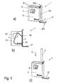
- Fig. 1 shows the spring clip according to the invention without inserted conductor 3, in the Fig. 1 (a) and (c) in a perspective view, and in Fig. 1 (b) a section through the spring clip 1 in a side view.
- the spring clip 1 has a housing part 5, in which a contact rail 2 and a clamping means 4 are arranged.
- the housing part 5 is formed substantially U-shaped and has two substantially mutually parallel leg surfaces 51, in each of which a securing window 53 and a storage means 54, a bearing window 54 are provided.
- storage means 54 and storage windows are used synonymously.
- the securing window 53 531 several securing teeth are arranged as securing means.
- the terms securing means 531 and safety tooth are used interchangeably.
- the leg surfaces 51 are connected to each other by means of a transverse surface 52, which is arranged substantially transversely to the leg surfaces 51.
- the contact rail 2 extends within the space enclosed by the housing part 5 space along the transverse surface 52. It protrudes out of the housing part 5 at a contact end 201 and is bent there to a tongue 21, to which an electrical assembly 7, here a conductor, the in Fig. 1 (c) is shown by way of example and schematically in dashed lines, can be connected. In addition, it also protrudes out of the housing part 5 at a plug-in end 202 and is bent there such that a conductor 3 when plugged into the spring clip 1 (see FIG. Fig. 1 (c) ) is guided in a plug-in direction 6 along the contact rail 2.
- the spring clip 1 further comprises an insulating housing 9, that in Fig. 1 (a) is shown schematically.
- Fig. 2 shows the spring clip the Fig. 1 with plugged in conductor 3, in Fig. 2 (a) in a perspective view, and in Fig. 2 (b) a section through the spring clip 1 in a side view. Also shows Fig. 3 in Fig. 3 (a) an enlarged section of the Fig. 2 (a) in another perspective view and in Fig. 3 (b) the cut AA through the Fig. 2 (a) in a side view.
- the clamping means 4 is symmetrical to a center plane 8 (s. Fig. 3 ) mounted in the housing part 5 by having two symmetrically arranged to the median plane 8 bearing edges 421, each extending into the bearing window 54 of the leg surfaces 51.
- the bearing windows 54 are provided substantially V-shaped, so that the clamping means 4 is rotatably movable about a pointed end 541 of the V-shaped bearing window 54.
- the bearing edge 421 extends over an entire width 542 of the bearing window 54, so that a displacement of the clamping means 4 transversely to the insertion direction 6 is not possible.
- the clamping means 4 further comprises two symmetrically arranged to the median plane 8 securing edges 411, each extending into the securing window 53 of the leg surfaces 51 and cooperate when pulling out the inserted conductor 3 against the insertion direction 6 with the securing teeth 531, which are arranged in the fuse window 53.
- Fig. 4 shows a clamping means 4, in Fig. 4 (a) in a perspective and in Fig. 4 (b) in a side view.
- the clamping means 4 is constructed substantially U-shaped and has a clamping leg 43, a bearing leg 42 and a connection leg 41 connecting the clamping leg 43 and the bearing leg 42.
- both the clamping leg 43 and the bearing leg 42 are arranged at an acute angle 40 to the connecting strut 41.
- the bearing leg 42 On the bearing leg 42 are symmetrical to the median plane 8 (s. Fig. 3 ) the two bearing edges 421 arranged. Furthermore, symmetrically to the center plane 8, the two securing edges 411 are arranged on the connecting strut 41. Finally, the clamping leg 43 has a clamping edge 431 with which it rests positively against the inserted conductor 3 and jams it.
- the clamping edge 431 moves almost in a straight line, independently of the conductor cross section of the inserted conductors 3, so that its position 10 relative to the height 11 (see FIG. Fig. 2 (b) ) of the housing part 5 as a function of the conductor cross section almost does not change.
- the clamping means 4 When pulling out the conductor 3 against the insertion direction 6, the clamping means 4 is raised until the securing edge 411 rests against one of the securing teeth 531. The conductor 3 is jammed at the clamping edge 431 so that it is secured against being pulled out.
- an actuating means (not shown) with which the clamping leg 43 is bendable so that the acute angle 40 between the clamping leg 43 and the connecting strut 41 is reduced, the conductor 3 of the spring clip 1 can be removed.
Landscapes
- Connections Arranged To Contact A Plurality Of Conductors (AREA)
- Clamps And Clips (AREA)
Claims (11)
- Borne à ressort (1) avec un rail de contact (2) pour la connexion électrique d'un conducteur (3) pouvant être inséré dans la borne à ressort (1) dans un sens d'insertion (6) avec un module électrique (7) ainsi qu'un moyen de serrage (4) pour serrer le conducteur (3) introduit dans la borne à ressort (1), le conducteur serré (3) venant en contact électrique avec le rail de contact (2), comprenant une partie de boîtier (5) qui comporte deux surfaces de bras (51) sensiblement parallèles l'une à l'autre, lesquelles surfaces de bras (51) présentent chacune aussi bien un moyen d'appui (54) pour l'appui du moyen de serrage (4) qu'un moyen de fixation (53) pour fixer le conducteur (3) afin d'empêcher son extraction en sens inverse du sens d'introduction (6),
caractérisée en ce que les surfaces de bras (51) comportent chacune comme moyen de fixation (53) au moins une dent de fixation, le moyen de serrage (4) comportant deux arêtes de fixation (411) disposées sur une entretoise de liaison (41), qui sont disposées de façon symétrique par rapport à un plan médian (8), la dent de fixation d'une surface de bras (51) coopérant avec une arête de fixation (411) du moyen de serrage (4). - Borne à ressort (1) selon la revendication 1, caractérisée en ce que la partie de boîtier (5) comprend une surface transversale (52) disposée transversalement par rapport aux surfaces de bras (51) et reliant celles-ci.
- Borne à ressort (1) selon l'une des revendications précédentes, caractérisée en ce que le rail de contact (2) s'étend à l'intérieur de la partie de boîtier (5) le long de la surface transversale (52).
- Borne à ressort (1) selon l'une des revendications précédentes, caractérisée en ce que le moyen de serrage (4) est disposé entre les surfaces de bras (51).
- Borne à ressort (1) selon l'une des revendications précédentes, caractérisée en ce que le moyen de serrage (4) est disposé de façon symétrique par rapport au plan médian (8) et celui-ci s'étend de façon sensiblement parallèle aux surfaces de bras (51).
- Borne à ressort (1) selon l'une des revendications précédentes, caractérisée en ce que les surfaces de bras (51) présentent chacune comme moyen d'appui (54) une fenêtre d'appui, le moyen de serrage (4) présentant sur son bras d'appui (42) deux arêtes d'appui (421) qui sont disposées de façon symétrique par rapport au plan médian (8) et avec lesquelles le moyen de serrage (4) s'appuie dans les fenêtres d'appui (54).
- Borne à ressort (1) selon l'une des revendications précédentes, caractérisée en ce que le moyen de serrage (4) est prévu pour être élastique de façon à retenir le conducteur (3) dans la position introduite (E).
- Borne à ressort (1) selon l'une des revendications précédentes, caractérisée en ce que le moyen de serrage (4) est sensiblement en forme de U et présente un bras d'appui (42) pour l'appui du moyen de serrage (4), un bras de serrage (43) pour le serrage du conducteur (3) et l'entretoise de liaison (41) reliant les bras (42, 43) du moyen de serrage (4), lesquels bras (42, 43) sont disposés chacun à angle aigu (40) par rapport à l'entretoise de liaison (41).
- Borne à ressort (1) selon la revendication 8, caractérisée en ce que le moyen de serrage (4) présente sur son bras de serrage (43) une arête de serrage (431) qui est prévue pour un contact en correspondance de forme avec le conducteur (3).
- Borne à ressort (1) selon l'une des revendications précédentes, caractérisée en ce qu'elle comprend un boîtier isolant.
- Borne à ressort (1) selon l'une des revendications précédentes, caractérisée en ce qu'il s'agit d'une borne de jonction et/ou d'une borne série.
Applications Claiming Priority (2)
| Application Number | Priority Date | Filing Date | Title |
|---|---|---|---|
| DE202010009666U DE202010009666U1 (de) | 2010-06-30 | 2010-06-30 | Miniatur-Federklemme |
| PCT/EP2011/060676 WO2012000919A1 (fr) | 2010-06-30 | 2011-06-27 | Pince à ressort miniature |
Publications (2)
| Publication Number | Publication Date |
|---|---|
| EP2589112A1 EP2589112A1 (fr) | 2013-05-08 |
| EP2589112B1 true EP2589112B1 (fr) | 2015-12-16 |
Family
ID=44483742
Family Applications (1)
| Application Number | Title | Priority Date | Filing Date |
|---|---|---|---|
| EP11727462.1A Not-in-force EP2589112B1 (fr) | 2010-06-30 | 2011-06-27 | Borne à ressort miniature |
Country Status (6)
| Country | Link |
|---|---|
| US (1) | US8771004B2 (fr) |
| EP (1) | EP2589112B1 (fr) |
| JP (1) | JP5768285B2 (fr) |
| CN (1) | CN102971913B (fr) |
| DE (1) | DE202010009666U1 (fr) |
| WO (1) | WO2012000919A1 (fr) |
Families Citing this family (18)
| Publication number | Priority date | Publication date | Assignee | Title |
|---|---|---|---|---|
| DE102011085872B4 (de) * | 2011-11-07 | 2023-03-23 | Lenze Se | Frequenzumrichter und Federelement hierfür |
| EP2792026B1 (fr) * | 2011-12-14 | 2017-08-23 | Ideal Industries Inc. | Connecteurs électriques destinés à être utilisés conjointement avec des cartes de circuit imprimé |
| US8870608B2 (en) | 2012-09-14 | 2014-10-28 | Schneider Electric USA, Inc. | Open spring mechanical clamping lug |
| NZ607726A (en) * | 2013-03-06 | 2014-09-26 | Gallagher Group Ltd | Securing device |
| DE102013109640B4 (de) * | 2013-09-04 | 2018-05-24 | Wago Verwaltungsgesellschaft Mbh | Federkraftanschlussklemme und Klemmenbauelement |
| DE102013110431A1 (de) * | 2013-09-20 | 2015-03-26 | Phoenix Contact Gmbh & Co. Kg | Verbindungsvorrichtung |
| DE102014103826A1 (de) * | 2014-03-20 | 2015-09-24 | Harting Electric Gmbh & Co. Kg | Paralleler Schraubanschluss |
| EP2947718B1 (fr) | 2014-05-23 | 2017-12-13 | Berker GmbH & Co. KG | Borne de connexion de serrage à ressort |
| TWI544705B (zh) * | 2014-09-05 | 2016-08-01 | 町洋企業股份有限公司 | 蝶形彈簧連接器 |
| TWM502983U (zh) * | 2014-12-04 | 2015-06-11 | Switchlab Inc | 軌道型電聯接端子之導電接線結構 |
| CN204558667U (zh) * | 2015-04-11 | 2015-08-12 | 江门市创艺电器有限公司 | 一种接线端子连接器 |
| DE202015104962U1 (de) * | 2015-09-18 | 2016-12-21 | Wago Verwaltungsgesellschaft Mbh | Leiteranschlussklemme |
| TWI619317B (zh) * | 2016-06-20 | 2018-03-21 | Improved structure of the connector head limiter of the wire connection terminal | |
| CN106374240B (zh) * | 2016-09-21 | 2018-07-20 | 上海航天科工电器研究院有限公司 | 一种带扭簧的锁线端子 |
| DE102017206776A1 (de) * | 2017-04-21 | 2018-10-25 | Siemens Aktiengesellschaft | Elektrisches Verbindungselement mit Klemmelement für Kabelende |
| DE202017105467U1 (de) | 2017-09-08 | 2018-12-12 | Wago Verwaltungsgesellschaft Mbh | Leiteranschlussklemme |
| TWI659581B (zh) * | 2018-03-16 | 2019-05-11 | 進聯工業股份有限公司 | Conductive component structure of wire coupling device |
| DE102018111216B3 (de) * | 2018-05-09 | 2019-10-17 | Semikron Elektronik Gmbh & Co. Kg | Schaltungsanordnung zur Strommessung in einer Leistungshalbleitergruppe und Leistungshalbleiterbaugruppe hiermit |
Family Cites Families (24)
| Publication number | Priority date | Publication date | Assignee | Title |
|---|---|---|---|---|
| US2713668A (en) * | 1951-06-21 | 1955-07-19 | Hart Mfg Co | Quick detachable electrical connector |
| DE2503091A1 (de) * | 1975-01-25 | 1976-07-29 | Hirschmann Radiotechnik | Federklemme zum anschliessen von elektrischen leitern |
| JPS60131969U (ja) * | 1984-02-13 | 1985-09-03 | 株式会社モリマツ | 中継端子台 |
| JPH0382562U (fr) * | 1989-12-12 | 1991-08-22 | ||
| IT229713Y1 (it) * | 1993-03-12 | 1999-01-29 | Vlm Spa | Portalampada per lampade alogene |
| JP2896736B2 (ja) * | 1993-08-25 | 1999-05-31 | モレックス インコーポレーテッド | 電気コネクタ |
| US5494456A (en) | 1994-10-03 | 1996-02-27 | Methode Electronics, Inc. | Wire-trap connector with anti-overstress member |
| JP3017433B2 (ja) * | 1995-09-05 | 2000-03-06 | 株式会社八光電機製作所 | 端子装置 |
| DE19613557A1 (de) * | 1995-12-22 | 1997-06-26 | Hager Electro Gmbh | Klemme zum Verbinden eines Leiterendes mit einem Kontakt |
| DE29608178U1 (de) * | 1996-05-06 | 1996-07-25 | Weidmüller Interface GmbH & Co, 32760 Detmold | Zugfederanschluß mit einsteckbarem Anschlagelement |
| DE19635135C1 (de) | 1996-08-30 | 1998-01-15 | Weidmueller Interface | Einrichtung zum Klemmen eines elektrischen Leiters |
| JPH1083850A (ja) | 1996-09-06 | 1998-03-31 | Osada:Kk | 端子台 |
| DE19817925B4 (de) * | 1998-04-17 | 2004-04-29 | Wago Verwaltungsgesellschaft Mbh | Federkraftklemmanschluß für elektrische Leiter |
| EP1253670B1 (fr) * | 2001-04-23 | 2006-04-26 | Weidmüller Interface GmbH & Co. | Borne à ressort et barette à bornes |
| DE10253858B4 (de) * | 2002-11-19 | 2004-09-16 | Gerd Conrad | Anschlußklemmelement und damit gebildete Anschlußklemme |
| DE102004046471B3 (de) * | 2004-09-23 | 2006-02-09 | Phoenix Contact Gmbh & Co. Kg | Elektrische Anschluß- oder Verbindungsklemme |
| DE202004019109U1 (de) * | 2004-12-10 | 2006-04-13 | Weidmüller Interface GmbH & Co. KG | Anschlussvorrichtung für elektrische Leiter mit Betätigungsvorrichtung |
| DE102006014646B4 (de) * | 2006-03-28 | 2008-06-26 | Phoenix Contact Gmbh & Co. Kg | Anschlussklemme für Leiterplatten |
| DE102007035336B3 (de) * | 2007-07-27 | 2009-02-05 | Phoenix Contact Gmbh & Co. Kg | Federkraftprintklemme |
| DE202008014469U1 (de) * | 2008-10-31 | 2010-03-18 | Weidmüller Interface GmbH & Co. KG | Anschlussklemme zum Anschluss von Leiterenden |
| DE202008016856U1 (de) * | 2008-12-22 | 2010-05-20 | Phoenix Contact Gmbh & Co. Kg | Elektrische Anschluss- oder Verbindungsklemme |
| DE102009004513A1 (de) * | 2009-01-09 | 2010-07-22 | Phoenix Contact Gmbh & Co. Kg | Klemmfeder für eine Federkraftklemme |
| DE202009010945U1 (de) * | 2009-08-14 | 2009-10-22 | Friedrich Göhringer Elektrotechnik GmbH | Sammelschienenanschlussklemme |
| US8408952B2 (en) * | 2011-05-19 | 2013-04-02 | Shang Tsai Wu | Wiring terminal structures |
-
2010
- 2010-06-30 DE DE202010009666U patent/DE202010009666U1/de not_active Expired - Lifetime
-
2011
- 2011-06-27 CN CN201180032322.9A patent/CN102971913B/zh not_active Expired - Fee Related
- 2011-06-27 JP JP2013517220A patent/JP5768285B2/ja not_active Expired - Fee Related
- 2011-06-27 US US13/701,742 patent/US8771004B2/en not_active Expired - Fee Related
- 2011-06-27 EP EP11727462.1A patent/EP2589112B1/fr not_active Not-in-force
- 2011-06-27 WO PCT/EP2011/060676 patent/WO2012000919A1/fr not_active Ceased
Also Published As
| Publication number | Publication date |
|---|---|
| US20130072072A1 (en) | 2013-03-21 |
| JP5768285B2 (ja) | 2015-08-26 |
| US8771004B2 (en) | 2014-07-08 |
| CN102971913A (zh) | 2013-03-13 |
| JP2013533591A (ja) | 2013-08-22 |
| DE202010009666U1 (de) | 2011-11-29 |
| EP2589112A1 (fr) | 2013-05-08 |
| WO2012000919A1 (fr) | 2012-01-05 |
| CN102971913B (zh) | 2016-03-23 |
Similar Documents
| Publication | Publication Date | Title |
|---|---|---|
| EP2589112A1 (fr) | Pince à ressort miniature | |
| DE102008017245B4 (de) | Steckadapter für ein elektrisches Schaltgerät | |
| DE102007022806B3 (de) | Klemmenbauteil | |
| EP2593991B1 (fr) | Pièce de contact électrique | |
| DE10355195B4 (de) | Leiteranschluss | |
| EP2522052B1 (fr) | Borne à ressort, en particulier borne frontale | |
| EP3595090B1 (fr) | Borne de connexion conductrice | |
| DE102016116510A1 (de) | Leiteranschlussklemme | |
| DE102012110759A1 (de) | Federkraftklemmanschluss und elektrisches Gerät hiermit | |
| DE202005005369U1 (de) | Anschlußvorrichtung zum Direktsteckanschluß von Leiterenden und elektrisches Gerät mit einer derartigen Anschlußvorrichtung | |
| DE102015101893A1 (de) | Leiteranschlussklemme | |
| DE10324144B4 (de) | Elektrische Reihenklemme und metallisches Schutzleiteranschlußelement zur Verwendung in einer elektrischen Reihenklemme | |
| DE9112178U1 (de) | Steckverbinder mit Kurzschlußbrücke | |
| WO2022136280A1 (fr) | Insert de contact pour borne de connexion de conducteur | |
| EP1691454B1 (fr) | Connecteur électrique avec crochets de fermeture | |
| EP2107660B1 (fr) | Connecteur de rails conducteurs | |
| DE102009043174A1 (de) | NH-Sicherungsschaltgerät | |
| DE102010050870B4 (de) | Niederspannungsschaltgerät mit einer Steckklemmvorrichtung | |
| DE10347668A1 (de) | Elektrische Klemme | |
| DE102013017157A1 (de) | Vorrichtung zur Montage mindestens eines als Steckmodul ausgebildeten Überspannungsschutzgeräts | |
| DE19816907B4 (de) | Schutzstecker für eine Einrichtung der Telekommunikationstechnik | |
| EP2684256B1 (fr) | Fiche de mise en contact pour la mise en contact directe d'une carte de circuits imprimés | |
| DE202015102561U1 (de) | Leiteranschlussklemme | |
| EP1432076B1 (fr) | Barette à bornes électrique | |
| EP2489100B1 (fr) | Borne à vis avec couvercle et appareil de coupure d'installation |
Legal Events
| Date | Code | Title | Description |
|---|---|---|---|
| PUAI | Public reference made under article 153(3) epc to a published international application that has entered the european phase |
Free format text: ORIGINAL CODE: 0009012 |
|
| 17P | Request for examination filed |
Effective date: 20130110 |
|
| AK | Designated contracting states |
Kind code of ref document: A1 Designated state(s): AL AT BE BG CH CY CZ DE DK EE ES FI FR GB GR HR HU IE IS IT LI LT LU LV MC MK MT NL NO PL PT RO RS SE SI SK SM TR |
|
| DAX | Request for extension of the european patent (deleted) | ||
| GRAP | Despatch of communication of intention to grant a patent |
Free format text: ORIGINAL CODE: EPIDOSNIGR1 |
|
| INTG | Intention to grant announced |
Effective date: 20150826 |
|
| GRAS | Grant fee paid |
Free format text: ORIGINAL CODE: EPIDOSNIGR3 |
|
| GRAA | (expected) grant |
Free format text: ORIGINAL CODE: 0009210 |
|
| AK | Designated contracting states |
Kind code of ref document: B1 Designated state(s): AL AT BE BG CH CY CZ DE DK EE ES FI FR GB GR HR HU IE IS IT LI LT LU LV MC MK MT NL NO PL PT RO RS SE SI SK SM TR |
|
| REG | Reference to a national code |
Ref country code: GB Ref legal event code: FG4D Free format text: NOT ENGLISH |
|
| REG | Reference to a national code |
Ref country code: CH Ref legal event code: EP |
|
| REG | Reference to a national code |
Ref country code: IE Ref legal event code: FG4D Free format text: LANGUAGE OF EP DOCUMENT: GERMAN |
|
| REG | Reference to a national code |
Ref country code: AT Ref legal event code: REF Ref document number: 765960 Country of ref document: AT Kind code of ref document: T Effective date: 20160115 |
|
| REG | Reference to a national code |
Ref country code: DE Ref legal event code: R096 Ref document number: 502011008516 Country of ref document: DE |
|
| REG | Reference to a national code |
Ref country code: NL Ref legal event code: MP Effective date: 20151216 |
|
| REG | Reference to a national code |
Ref country code: LT Ref legal event code: MG4D |
|
| PG25 | Lapsed in a contracting state [announced via postgrant information from national office to epo] |
Ref country code: NO Free format text: LAPSE BECAUSE OF FAILURE TO SUBMIT A TRANSLATION OF THE DESCRIPTION OR TO PAY THE FEE WITHIN THE PRESCRIBED TIME-LIMIT Effective date: 20160316 Ref country code: LT Free format text: LAPSE BECAUSE OF FAILURE TO SUBMIT A TRANSLATION OF THE DESCRIPTION OR TO PAY THE FEE WITHIN THE PRESCRIBED TIME-LIMIT Effective date: 20151216 Ref country code: HR Free format text: LAPSE BECAUSE OF FAILURE TO SUBMIT A TRANSLATION OF THE DESCRIPTION OR TO PAY THE FEE WITHIN THE PRESCRIBED TIME-LIMIT Effective date: 20151216 |
|
| PG25 | Lapsed in a contracting state [announced via postgrant information from national office to epo] |
Ref country code: GR Free format text: LAPSE BECAUSE OF FAILURE TO SUBMIT A TRANSLATION OF THE DESCRIPTION OR TO PAY THE FEE WITHIN THE PRESCRIBED TIME-LIMIT Effective date: 20160317 Ref country code: FI Free format text: LAPSE BECAUSE OF FAILURE TO SUBMIT A TRANSLATION OF THE DESCRIPTION OR TO PAY THE FEE WITHIN THE PRESCRIBED TIME-LIMIT Effective date: 20151216 Ref country code: RS Free format text: LAPSE BECAUSE OF FAILURE TO SUBMIT A TRANSLATION OF THE DESCRIPTION OR TO PAY THE FEE WITHIN THE PRESCRIBED TIME-LIMIT Effective date: 20151216 Ref country code: LV Free format text: LAPSE BECAUSE OF FAILURE TO SUBMIT A TRANSLATION OF THE DESCRIPTION OR TO PAY THE FEE WITHIN THE PRESCRIBED TIME-LIMIT Effective date: 20151216 Ref country code: SE Free format text: LAPSE BECAUSE OF FAILURE TO SUBMIT A TRANSLATION OF THE DESCRIPTION OR TO PAY THE FEE WITHIN THE PRESCRIBED TIME-LIMIT Effective date: 20151216 Ref country code: NL Free format text: LAPSE BECAUSE OF FAILURE TO SUBMIT A TRANSLATION OF THE DESCRIPTION OR TO PAY THE FEE WITHIN THE PRESCRIBED TIME-LIMIT Effective date: 20151216 |
|
| PG25 | Lapsed in a contracting state [announced via postgrant information from national office to epo] |
Ref country code: CZ Free format text: LAPSE BECAUSE OF FAILURE TO SUBMIT A TRANSLATION OF THE DESCRIPTION OR TO PAY THE FEE WITHIN THE PRESCRIBED TIME-LIMIT Effective date: 20151216 Ref country code: ES Free format text: LAPSE BECAUSE OF FAILURE TO SUBMIT A TRANSLATION OF THE DESCRIPTION OR TO PAY THE FEE WITHIN THE PRESCRIBED TIME-LIMIT Effective date: 20151216 Ref country code: IT Free format text: LAPSE BECAUSE OF FAILURE TO SUBMIT A TRANSLATION OF THE DESCRIPTION OR TO PAY THE FEE WITHIN THE PRESCRIBED TIME-LIMIT Effective date: 20151216 |
|
| PG25 | Lapsed in a contracting state [announced via postgrant information from national office to epo] |
Ref country code: PT Free format text: LAPSE BECAUSE OF FAILURE TO SUBMIT A TRANSLATION OF THE DESCRIPTION OR TO PAY THE FEE WITHIN THE PRESCRIBED TIME-LIMIT Effective date: 20160418 Ref country code: SM Free format text: LAPSE BECAUSE OF FAILURE TO SUBMIT A TRANSLATION OF THE DESCRIPTION OR TO PAY THE FEE WITHIN THE PRESCRIBED TIME-LIMIT Effective date: 20151216 Ref country code: EE Free format text: LAPSE BECAUSE OF FAILURE TO SUBMIT A TRANSLATION OF THE DESCRIPTION OR TO PAY THE FEE WITHIN THE PRESCRIBED TIME-LIMIT Effective date: 20151216 Ref country code: RO Free format text: LAPSE BECAUSE OF FAILURE TO SUBMIT A TRANSLATION OF THE DESCRIPTION OR TO PAY THE FEE WITHIN THE PRESCRIBED TIME-LIMIT Effective date: 20151216 Ref country code: SK Free format text: LAPSE BECAUSE OF FAILURE TO SUBMIT A TRANSLATION OF THE DESCRIPTION OR TO PAY THE FEE WITHIN THE PRESCRIBED TIME-LIMIT Effective date: 20151216 Ref country code: IS Free format text: LAPSE BECAUSE OF FAILURE TO SUBMIT A TRANSLATION OF THE DESCRIPTION OR TO PAY THE FEE WITHIN THE PRESCRIBED TIME-LIMIT Effective date: 20160416 |
|
| REG | Reference to a national code |
Ref country code: DE Ref legal event code: R097 Ref document number: 502011008516 Country of ref document: DE |
|
| PLBE | No opposition filed within time limit |
Free format text: ORIGINAL CODE: 0009261 |
|
| STAA | Information on the status of an ep patent application or granted ep patent |
Free format text: STATUS: NO OPPOSITION FILED WITHIN TIME LIMIT |
|
| PG25 | Lapsed in a contracting state [announced via postgrant information from national office to epo] |
Ref country code: DK Free format text: LAPSE BECAUSE OF FAILURE TO SUBMIT A TRANSLATION OF THE DESCRIPTION OR TO PAY THE FEE WITHIN THE PRESCRIBED TIME-LIMIT Effective date: 20151216 Ref country code: PL Free format text: LAPSE BECAUSE OF FAILURE TO SUBMIT A TRANSLATION OF THE DESCRIPTION OR TO PAY THE FEE WITHIN THE PRESCRIBED TIME-LIMIT Effective date: 20151216 |
|
| 26N | No opposition filed |
Effective date: 20160919 |
|
| PG25 | Lapsed in a contracting state [announced via postgrant information from national office to epo] |
Ref country code: BE Free format text: LAPSE BECAUSE OF NON-PAYMENT OF DUE FEES Effective date: 20160630 |
|
| REG | Reference to a national code |
Ref country code: DE Ref legal event code: R119 Ref document number: 502011008516 Country of ref document: DE |
|
| PG25 | Lapsed in a contracting state [announced via postgrant information from national office to epo] |
Ref country code: MC Free format text: LAPSE BECAUSE OF FAILURE TO SUBMIT A TRANSLATION OF THE DESCRIPTION OR TO PAY THE FEE WITHIN THE PRESCRIBED TIME-LIMIT Effective date: 20151216 |
|
| REG | Reference to a national code |
Ref country code: CH Ref legal event code: PL |
|
| PG25 | Lapsed in a contracting state [announced via postgrant information from national office to epo] |
Ref country code: SI Free format text: LAPSE BECAUSE OF FAILURE TO SUBMIT A TRANSLATION OF THE DESCRIPTION OR TO PAY THE FEE WITHIN THE PRESCRIBED TIME-LIMIT Effective date: 20151216 |
|
| GBPC | Gb: european patent ceased through non-payment of renewal fee |
Effective date: 20160627 |
|
| REG | Reference to a national code |
Ref country code: IE Ref legal event code: MM4A |
|
| REG | Reference to a national code |
Ref country code: FR Ref legal event code: ST Effective date: 20170228 |
|
| PG25 | Lapsed in a contracting state [announced via postgrant information from national office to epo] |
Ref country code: DE Free format text: LAPSE BECAUSE OF NON-PAYMENT OF DUE FEES Effective date: 20170103 Ref country code: CH Free format text: LAPSE BECAUSE OF NON-PAYMENT OF DUE FEES Effective date: 20160630 Ref country code: FR Free format text: LAPSE BECAUSE OF NON-PAYMENT OF DUE FEES Effective date: 20160630 Ref country code: LI Free format text: LAPSE BECAUSE OF NON-PAYMENT OF DUE FEES Effective date: 20160630 |
|
| PG25 | Lapsed in a contracting state [announced via postgrant information from national office to epo] |
Ref country code: IE Free format text: LAPSE BECAUSE OF NON-PAYMENT OF DUE FEES Effective date: 20160627 Ref country code: GB Free format text: LAPSE BECAUSE OF NON-PAYMENT OF DUE FEES Effective date: 20160627 |
|
| REG | Reference to a national code |
Ref country code: AT Ref legal event code: MM01 Ref document number: 765960 Country of ref document: AT Kind code of ref document: T Effective date: 20160627 |
|
| PG25 | Lapsed in a contracting state [announced via postgrant information from national office to epo] |
Ref country code: AT Free format text: LAPSE BECAUSE OF NON-PAYMENT OF DUE FEES Effective date: 20160627 |
|
| PG25 | Lapsed in a contracting state [announced via postgrant information from national office to epo] |
Ref country code: CY Free format text: LAPSE BECAUSE OF FAILURE TO SUBMIT A TRANSLATION OF THE DESCRIPTION OR TO PAY THE FEE WITHIN THE PRESCRIBED TIME-LIMIT Effective date: 20151216 Ref country code: HU Free format text: LAPSE BECAUSE OF FAILURE TO SUBMIT A TRANSLATION OF THE DESCRIPTION OR TO PAY THE FEE WITHIN THE PRESCRIBED TIME-LIMIT; INVALID AB INITIO Effective date: 20110627 |
|
| PG25 | Lapsed in a contracting state [announced via postgrant information from national office to epo] |
Ref country code: LU Free format text: LAPSE BECAUSE OF NON-PAYMENT OF DUE FEES Effective date: 20160627 Ref country code: MK Free format text: LAPSE BECAUSE OF FAILURE TO SUBMIT A TRANSLATION OF THE DESCRIPTION OR TO PAY THE FEE WITHIN THE PRESCRIBED TIME-LIMIT Effective date: 20151216 Ref country code: TR Free format text: LAPSE BECAUSE OF FAILURE TO SUBMIT A TRANSLATION OF THE DESCRIPTION OR TO PAY THE FEE WITHIN THE PRESCRIBED TIME-LIMIT Effective date: 20151216 Ref country code: MT Free format text: LAPSE BECAUSE OF FAILURE TO SUBMIT A TRANSLATION OF THE DESCRIPTION OR TO PAY THE FEE WITHIN THE PRESCRIBED TIME-LIMIT Effective date: 20151216 |
|
| PG25 | Lapsed in a contracting state [announced via postgrant information from national office to epo] |
Ref country code: BG Free format text: LAPSE BECAUSE OF FAILURE TO SUBMIT A TRANSLATION OF THE DESCRIPTION OR TO PAY THE FEE WITHIN THE PRESCRIBED TIME-LIMIT Effective date: 20151216 |
|
| PG25 | Lapsed in a contracting state [announced via postgrant information from national office to epo] |
Ref country code: AL Free format text: LAPSE BECAUSE OF FAILURE TO SUBMIT A TRANSLATION OF THE DESCRIPTION OR TO PAY THE FEE WITHIN THE PRESCRIBED TIME-LIMIT Effective date: 20151216 |