EP2593991B1 - Pièce de contact électrique - Google Patents
Pièce de contact électrique Download PDFInfo
- Publication number
- EP2593991B1 EP2593991B1 EP11745719.2A EP11745719A EP2593991B1 EP 2593991 B1 EP2593991 B1 EP 2593991B1 EP 11745719 A EP11745719 A EP 11745719A EP 2593991 B1 EP2593991 B1 EP 2593991B1
- Authority
- EP
- European Patent Office
- Prior art keywords
- contact
- fork
- contact part
- electrical contact
- electrical
- Prior art date
- Legal status (The legal status is an assumption and is not a legal conclusion. Google has not performed a legal analysis and makes no representation as to the accuracy of the status listed.)
- Revoked
Links
Images




Classifications
-
- H—ELECTRICITY
- H01—ELECTRIC ELEMENTS
- H01R—ELECTRICALLY-CONDUCTIVE CONNECTIONS; STRUCTURAL ASSOCIATIONS OF A PLURALITY OF MUTUALLY-INSULATED ELECTRICAL CONNECTING ELEMENTS; COUPLING DEVICES; CURRENT COLLECTORS
- H01R13/00—Details of coupling devices of the kinds covered by groups H01R12/70 or H01R24/00 - H01R33/00
- H01R13/02—Contact members
- H01R13/10—Sockets for co-operation with pins or blades
- H01R13/11—Resilient sockets
- H01R13/113—Resilient sockets co-operating with pins or blades having a rectangular transverse section
-
- H—ELECTRICITY
- H01—ELECTRIC ELEMENTS
- H01R—ELECTRICALLY-CONDUCTIVE CONNECTIONS; STRUCTURAL ASSOCIATIONS OF A PLURALITY OF MUTUALLY-INSULATED ELECTRICAL CONNECTING ELEMENTS; COUPLING DEVICES; CURRENT COLLECTORS
- H01R11/00—Individual connecting elements providing two or more spaced connecting locations for conductive members which are, or may be, thereby interconnected, e.g. end pieces for wires or cables supported by the wire or cable and having means for facilitating electrical connection to some other wire, terminal, or conductive member, blocks of binding posts
- H01R11/03—Individual connecting elements providing two or more spaced connecting locations for conductive members which are, or may be, thereby interconnected, e.g. end pieces for wires or cables supported by the wire or cable and having means for facilitating electrical connection to some other wire, terminal, or conductive member, blocks of binding posts characterised by the relationship between the connecting locations
- H01R11/05—Individual connecting elements providing two or more spaced connecting locations for conductive members which are, or may be, thereby interconnected, e.g. end pieces for wires or cables supported by the wire or cable and having means for facilitating electrical connection to some other wire, terminal, or conductive member, blocks of binding posts characterised by the relationship between the connecting locations the connecting locations having different types of direct connections
-
- H—ELECTRICITY
- H01—ELECTRIC ELEMENTS
- H01R—ELECTRICALLY-CONDUCTIVE CONNECTIONS; STRUCTURAL ASSOCIATIONS OF A PLURALITY OF MUTUALLY-INSULATED ELECTRICAL CONNECTING ELEMENTS; COUPLING DEVICES; CURRENT COLLECTORS
- H01R13/00—Details of coupling devices of the kinds covered by groups H01R12/70 or H01R24/00 - H01R33/00
- H01R13/02—Contact members
- H01R13/04—Pins or blades for co-operation with sockets
- H01R13/05—Resilient pins or blades
-
- H—ELECTRICITY
- H01—ELECTRIC ELEMENTS
- H01R—ELECTRICALLY-CONDUCTIVE CONNECTIONS; STRUCTURAL ASSOCIATIONS OF A PLURALITY OF MUTUALLY-INSULATED ELECTRICAL CONNECTING ELEMENTS; COUPLING DEVICES; CURRENT COLLECTORS
- H01R13/00—Details of coupling devices of the kinds covered by groups H01R12/70 or H01R24/00 - H01R33/00
- H01R13/02—Contact members
- H01R13/10—Sockets for co-operation with pins or blades
- H01R13/11—Resilient sockets
- H01R13/112—Resilient sockets forked sockets having two legs
-
- H—ELECTRICITY
- H01—ELECTRIC ELEMENTS
- H01R—ELECTRICALLY-CONDUCTIVE CONNECTIONS; STRUCTURAL ASSOCIATIONS OF A PLURALITY OF MUTUALLY-INSULATED ELECTRICAL CONNECTING ELEMENTS; COUPLING DEVICES; CURRENT COLLECTORS
- H01R12/00—Structural associations of a plurality of mutually-insulated electrical connecting elements, specially adapted for printed circuits, e.g. printed circuit boards [PCB], flat or ribbon cables, or like generally planar structures, e.g. terminal strips, terminal blocks; Coupling devices specially adapted for printed circuits, flat or ribbon cables, or like generally planar structures; Terminals specially adapted for contact with, or insertion into, printed circuits, flat or ribbon cables, or like generally planar structures
- H01R12/70—Coupling devices
- H01R12/71—Coupling devices for rigid printing circuits or like structures
- H01R12/72—Coupling devices for rigid printing circuits or like structures coupling with the edge of the rigid printed circuits or like structures
- H01R12/721—Coupling devices for rigid printing circuits or like structures coupling with the edge of the rigid printed circuits or like structures cooperating directly with the edge of the rigid printed circuits
-
- H—ELECTRICITY
- H01—ELECTRIC ELEMENTS
- H01R—ELECTRICALLY-CONDUCTIVE CONNECTIONS; STRUCTURAL ASSOCIATIONS OF A PLURALITY OF MUTUALLY-INSULATED ELECTRICAL CONNECTING ELEMENTS; COUPLING DEVICES; CURRENT COLLECTORS
- H01R9/00—Structural associations of a plurality of mutually-insulated electrical connecting elements, e.g. terminal strips or terminal blocks; Terminals or binding posts mounted upon a base or in a case; Bases therefor
- H01R9/22—Bases, e.g. strip, block, panel
- H01R9/24—Terminal blocks
- H01R9/26—Clip-on terminal blocks for side-by-side rail- or strip-mounting
- H01R9/2675—Electrical interconnections between two blocks, e.g. by means of busbars
Definitions
- the present invention relates to an electrical contact part according to the preamble of claim 1.
- Switchgear for example, for machines or production lines are known, which have connection modules for controlling and monitoring sensors, initiators, field devices and / or actuators, via which they are electrically connected to the machines and production lines.
- connection modules for controlling and monitoring sensors, initiators, field devices and / or actuators, via which they are electrically connected to the machines and production lines.
- connection modules are usually provided next to each other modular and interconnected to form a terminal block.
- a bus is usually provided, which is led from one connection module into the next and comprises one or more bus lines.
- Such a bus usually includes both signal and supply lines.
- the DE 199 64 156 A1 discloses a switchgear in which a connection module each having a plurality of diagnostic interfaces for connecting the sensors, initiators, field devices and / or actuators, which are electrically guided by busbars to terminal contacts, to which a circuit board of the connection module can be connected.
- the connection module contact parts (s. Fig. 5 to the prior art).
- the contact parts have, in addition to a contact fork 201, to which the circuit board can be connected, in each case a blade contact part 202 and a socket contact part 203.
- the blade contact part of the one connection module is connected to the socket contact part of the adjacent connection module and electrically contacted.
- the contact parts therefore form the bus line for the supply voltage.
- a generic contact part is from the DE 197 18 996 C1 known.
- Object of the present invention is to improve the generic electrical contact part, in particular for forwarding a supply voltage to the effect that it is in a vibration-prone environment a continuous and ensures high-quality connection, and also easy to connect and cost manufacturable.
- both contact spring legs each have a contact blade portion, the current is passed through both contact blade sections to the adjacent contact part, and not just by a single knife.
- the first contact spring limb and the second contact spring limb are preferably arranged symmetrically with respect to a first center plane, so that a current flowing through the electrical contact part is distributed substantially uniformly over both contact spring limbs.
- the first contact spring legs and second contact spring legs in the region of the fork sections by means of a transverse strut, which is arranged transversely to the median plane, electrically and preferably also mechanically interconnected.
- the bushing sections of the first and second contact spring leg and the transverse strut thereby form a substantially U-shaped insertion region into which the contact blade sections of the adjacent contact part can be inserted.
- the crossbar the contact part sufficient rigidity. The handling of the contact parts is therefore easy.
- the contact fork is thereby also in one piece.
- the crossbar is dimensioned so that their current carrying capacity of the total current carrying capacity of both contact spring leg corresponds.
- the contact spring legs are each resiliently designed at least at one of their ends. As a result, the contact blade portion of each contact spring leg is located in the plug state with a restoring force to a non-or substantially non-resilient fork portion of the contact spring leg of the adjacent contact part.
- the contact part according to the invention has the advantage that the two contact blade sections can not virtually free due to the restoring force of the contact spring leg and the electrical contact is therefore made very reliable even in a vibration prone environment.
- the contact blade thus consists of two when inserting into the first contact fork resiliently compressible single legs.
- the electrical contact part likewise preferably comprises a further connection means, in particular for connecting an electrical assembly.
- an assembly is for example an electrical circuit board or a conductor.
- the further connection means is particularly preferably a second contact fork.
- this second contact fork has two contact fork legs, which are arranged parallel to a second center plane which extends transversely to the first center plane.
- the second contact fork engages around a contact means of the electrical assembly, so that the electrical contact during assembly of the electrical contact member with the electrical assembly is made safe.
- the arrangement of the two contact forks parallel to the respectively transversely arranged center planes has the advantage that the plane in which the bus formed by the contact part is arranged outside, for example above or below, the plane is arranged, in which the electrical assembly is provided.
- the electric Assembly is therefore connectable to the contact part without entering the area of the contact fork. In the case of a faulty mounting, the electrical assembly therefore does not get into the area of the contact fork or the bus and therefore does not endanger the through-connection of further connected contact parts, and thus further connection modules.
- the contact fork legs are connected to each other by means of the transverse strut, so that no additional connection means between the first contact fork and the second contact fork are needed.
- the first contact fork and the second contact fork are made in one piece with each other.
- the contact part is preferably made as a stamped and bent part of a metal sheet. The arrangement of the contact fork and the contact fork to the crossbar allows a very space-saving punching pattern, so that only a very small waste produced. As a result, the contact part is very inexpensive manufacturable. Furthermore, the contact part with very low manufacturing tolerances and a high rigidity can be produced.
- the spring action of the contact spring legs can be achieved by appropriate bending of the contact spring leg.
- connection module with an electrical contact part according to the invention.
- connection block comprising at least two connection modules with electrical contact parts according to the invention.
- the electrical contact part allows a safe bus connection between two adjacent connection modules, especially for the supply voltage, even in a vibration-prone environment.
- Fig. 1 shows in (a) an inventive electrical contact part 100 in a side view, wherein the Fig. 1 (b) the electrical contact part of Fig. 1 (a) from the left, the Fig. 1 (c) the electrical contact part from the right, the Fig. 1 (d) the electrical contact part from above and the Fig. 1 (e) shows the electrical contact part from below.
- the contact part 100 has a contact spring arrangement 1 for connecting an adjacent electrical contact part 100 '.
- the contact spring arrangement 1 comprises a first contact spring leg 11 and a second contact spring leg 12, which are arranged symmetrically to a first center plane 10.
- the contact spring legs 11, 12 each have a contact blade portion 111, 121 and a fork portion 113, 123. In the region of the fork section 113, 123, the contact spring legs 11, 12 are electrically connected to one another by means of a transverse strut 23, which is arranged transversely to the first center plane 10.
- the cross member 23 connects the contact spring legs 11, 12 also mechanically -here in one piece - each other
- the cross member 23 and the fork portions 113, 123 form a substantially U-shaped insertion region 230 (see Fig. 3 (a) . 4 (b) ), in which the contact spring legs 11 ', 12' of an adjacent contact part 100 'can be inserted.
- An embodiment is also preferred in which the side 33 opposite the transverse strut 23 also has a second transverse strut (not shown), so that the insertion region 230 is in particular completely closed.
- the contact blade sections 111, 121 of the contact part 100 do not touch.
- connection means 2 for connecting an electrical assembly 4 (s. Fig. 3 (b) ) a second contact fork 2 with two arranged symmetrically to a second center plane 20 contact fork legs 21.
- electrical assembly 4 s. Fig. 3 (b)
- second contact fork 2 with two arranged symmetrically to a second center plane 20 contact fork legs 21.
- connecting means 2 and contact fork are used interchangeably.
- the second center plane 20 extends transversely to the first center plane 10 and transversely to the transverse strut 23.
- the contact fork legs 21 are arranged on the transverse strut 23 and only connected via these.
- the electrical assembly 4 can be inserted between the contact fork legs 21.
- the contact fork legs 21 are each facing away from the contact spring arrangement 1 End 31 bent so that the assembly 4 is guided into the contact fork 2 into it.
- the contact fork legs 21, at least at the bend have a contact zone 210 with which they electrically contact the electrical assembly 4.
- the assembly 4 is preferably a populated printed circuit board. Due to the arrangement of the contact fork legs 21 via the contact fork sections 113, 123, the printed circuit board can be arranged in a surrounding housing, for example a series-terminal I / O module, close to the housing wall on the outside.
- the contact part 100 is preferably made in one piece simply as a stamped and bent part from a metal sheet.
- Fig. 2 shows a punching pattern 111 for the production of the electrical contact part 100 of Fig. 1
- the contact part 100 can be produced from the sheet after punching, in that the contact fork limbs 21 are in a substantially parallel position to the second center plane 20 (FIG. Fig. 3a ) and the contact spring legs 11, 12 in a substantially parallel position to the first center plane 10 (FIG. Fig. 3a ) are bent.
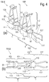
- Fig. 3 shows the electrical contact part 100 of Fig. 1 in a perspective view, wherein the Fig. 3 (a) the contact part 100 without electrical assembly 4 and the Fig. 3 (b) with connected electrical module 4 show. Visible is the substantially vertical arrangement of the first center plane 10 and the second center plane 20 (FIG. Fig. 3a ) to each other. By virtue of this arrangement, an electrical assembly 4 does not get into the region of the bus formed by the contact spring legs 11, 12 and therefore does not disturb the electrical contact of the bus.
- Fig. 4 shows an electrical contact part 100, which is inserted to form an electric bus in an adjacent electrical contact part 100 ', in Fig. 4 (a) in a perspective view and in Fig. 4 (b) in a bottom view. Both contact parts 100, 100 'correspond to the embodiment of the Fig. 1 ,
- the transverse strut 23 'and the fork sections 113', 123 'of the adjacent contact part 100' form the substantially U-shaped insertion region 230 'into which the contact blade sections 111, 121 of the electrical contact part 100 are inserted.
- the contact spring legs 11, 12 are bent at their end remote from the contact fork 2 32 so that they point away from the fork portion 113, 123, where they are in the insertion state E.
- insertion of the contact blade sections 111, 121 into the insertion region 230 'of the adjacent contact part 100' is simple.
- the contact blade sections 111, 121 thereby additionally each have a contact zone 110, with which they rest against a fork section 113 ', 123' of one of the contact spring legs 11 ', 12' of the adjacent contact part 100 '.
- the contact blade sections 111, 121 are compressed, so that the contact spring legs 11, 12 of the contact part 100 are tensioned.
- the contact spring legs 11, 12 therefore rest against the contact spring legs 11 '12' of the adjacent contact part 100 ', which counteracts detachment of the contact part 100 from the plug-in area 230' of the adjacent contact part 100 '.
- the electrical contact of the adjacent contact parts 100, 100 ' is therefore ensured.
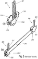
- Fig. 5 shows in Fig. 5 (a) an embodiment of an electrical contact part according to the prior art, and in Fig. 5 (b) two nested contact parts of the embodiment of the Fig. 5 (a) , The knife 202 'of the adjacent contact part 200' is formed extended here.
- the contact part 200 in each case a contact fork 201 for connecting an electrical assembly (not shown here) and a socket 203 for receiving a knife 202 of an adjacent contact part 200 'on.
- the bushing 203 has two opposite bushing legs 2031, 2032.
- the knife 202 is formed here merely as an extension of one of the two bushing legs 2031 forming the bushing 203.
- the contact fork 201 is also arranged only on this bushing leg 2031. As a result, the current carrying capacity of this contact part 200 according to the prior art is lower.
- a further embodiment of a contact part 100 according to the invention is shown.
- the two embodiments is compared to the embodiment of Fig. 1 - 4th in common that the fork portions 113, 123 of the first contact spring leg 11 and the second contact spring leg 12 are each extended at their the contact blade sections 111, 121 side facing away, so that they form fork legs 112, 122.
- the insertion space 230 is therefore formed in these embodiments, not only by the space between the contact spring legs 11, 12 in the region of the transverse web 23, but extends between the fork legs 112, 122nd
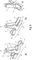
- the 8 (a) and (b) show the electrical contact part 100 of Fig. 6 in different perspective views.
- the fork legs 112, 122 extend approximately parallel to the first center plane 10 and are spaced from each other.
- the contact blade sections 111, 121 respectively facing away from the ends 34, they are each bent outwards, so they do not hinder the contact blade sections 111 ', 121' of an adjacent contact part 100 'when inserted into the insertion space 230.
- the Fig. 8 (c) shows by way of example two contact parts 100, 100 'of Fig. 6 in which the contact blade sections 111, 112 of a contact part 100 between the fork legs 112 ', 122' of an adjacent contact part 100 'are inserted and contact them electrically.
- the fork portions 113, 123 of the embodiment of the Fig. 9 extended even further and each have a bend 13 by 180 °, so that the fork legs 112, 122 are each formed by two adjoining leg portions 1121, 1122, 1221, 1222. This gives the fork legs 112, 122 a higher stability.
- the fork sections 113, 123 of the embodiments of contact parts 100 according to the invention shown here have an advantageous optional molding 35, which, inter alia, contributes to the stabilization of the fork.
- the Anformung is in the embodiments of Fig. 6-8 and 9 each provided on the fork legs 113, 123.
- it is also bent by 90 °, so that it extends transversely to the first and second center plane 10, 20 and extending from the fork legs 113, 123 below the insertion space 230 extends.
- the fork legs 113, 123 thereby always spaced.
- the projections 35 facilitate guiding the contact spring sections 111, 121 between the fork legs 113 ', 123' of an adjacent contact part 100 '.
Landscapes
- Coupling Device And Connection With Printed Circuit (AREA)
Claims (13)
- Élément de contact électrique (100) pour une ligne de bus extensible de façon modulaire, qui présente une première fourche de contact (1) pour le raccordement et la mise en contact d'un élément de contact électrique voisin (100'), dans lequel la fourche de contact (1) présente un premier bras de ressort de contact (11) et un deuxième bras de ressort de contact (12) qui sont reliés électriquement entre eux, le premier bras de ressort de contact (11) et le deuxième bras de ressort de contact (12) présentant chacun une partie de fourche (113, 123), le premier bras de ressort de contact (11) et le bras de ressort de contact (12) présentant en outre chacun une partie formant lame de contact (111, 121), et qui présente en outre une deuxième fourche de contact (2) pour le raccordement d'un module électrique (4), en particulier d'une carte de circuits,
dans lequel une zone d'enfichage (230) pour l'enfichage des parties formant lame de contact (111', 121') d'un élément de contact électrique voisin (100') s'étend entre les parties de fourche (113, 123) de la première fourche de contact (1) de l'élément de contact électrique (100),
caractérisé en ce que les parties formant lame de contact (100, 121) de l'élément de contact (100) ne se touchent pas, au moins dans un état libre dans lequel elles ne sont pas enfichées dans la zone d'enfichage (230') de l'élément de contact voisin (100'). - Élément de contact électrique (100) selon la revendication 1, caractérisé en ce que le premier bras de ressort de contact (11) et le deuxième bras de ressort de contact (12) sont disposés de façon symétrique par rapport à un premier plan central (10).
- Élément de contact électrique (100) selon l'une des revendications précédentes, caractérisé en ce que le premier bras de ressort de contact (11) et le deuxième bras de ressort de contact (12) sont reliés entre eux de façon mécanique et de préférence électriquement conductrice au moyen d'une traverse (23) qui s'étend perpendiculairement au plan central (10).
- Élément de contact électrique (100) selon l'une des revendications précédentes, caractérisé en ce que dans un état d'enfichage (E) dans lequel l'élément de contact électrique (100) est assemblé à un élément de contact électrique voisin (100'), chaque partie formant lame de contact (111, 121) de l'élément de contact électrique (100) repose en contact électrique sur une partie de fourche (113', 123') correspondante de l'élément de contact voisin (100').
- Élément de contact électrique (100) selon l'une des revendications précédentes, caractérisé en ce que le bras de ressort de contact (11, 12) est réalisé de façon élastique, en particulier au niveau de la partie formant lame de contact.
- Élément de contact électrique (100) selon l'une des revendications précédentes, caractérisé en ce que la deuxième fourche de contact (2) présente deux bras de fourche de contact (21) qui sont disposées parallèlement à un deuxième plan central (20) qui s'étend transversalement par rapport au premier plan central (10).
- Élément de contact électrique (100) selon l'une des revendications précédentes, caractérisé en ce que la carte de circuits est disposée de façon excentrée dans un boîtier d'entourage.
- Élément de contact électrique (100) selon l'une des revendications précédentes, caractérisé en ce que la première fourche de contact (1) et la deuxième fourche de contact (2) sont fabriquées ensemble d'un seul tenant.
- Élément de contact électrique (100) selon l'une des revendications précédentes, caractérisé en ce que les bras de fourche de contact (21) de la deuxième fourche de contact (2) sont reliés entre eux d'un seul tenant au moyen de la traverse (23).
- Élément de contact électrique (100) selon l'une des revendications précédentes, caractérisé en ce que les parties de fourche (113, 123) sont allongées sur leur côté tourné à l'opposé des parties formant lame de contact (111, 121) de manière à former des bras de fourche (112, 122) entre lesquels s'étend la zone d'enfichage (230).
- Élément de contact électrique (100) selon l'une des revendications précédentes, caractérisé en ce que les bras de fourche (112, 122) sont repliés à 180° à leurs extrémités (34) opposées aux parties formant lame de contact (111, 121).
- Module de raccordement avec un élément de contact électrique (100) selon l'une des revendications précédentes.
- Bloc de raccordement comprenant au moins deux modules de raccordement selon la revendication 12.
Applications Claiming Priority (2)
| Application Number | Priority Date | Filing Date | Title |
|---|---|---|---|
| DE202010010275U DE202010010275U1 (de) | 2010-07-15 | 2010-07-15 | Elektrisches Kontaktteil |
| PCT/EP2011/061985 WO2012007518A1 (fr) | 2010-07-15 | 2011-07-13 | Pièce de contact électrique |
Publications (2)
| Publication Number | Publication Date |
|---|---|
| EP2593991A1 EP2593991A1 (fr) | 2013-05-22 |
| EP2593991B1 true EP2593991B1 (fr) | 2016-04-20 |
Family
ID=44503776
Family Applications (1)
| Application Number | Title | Priority Date | Filing Date |
|---|---|---|---|
| EP11745719.2A Revoked EP2593991B1 (fr) | 2010-07-15 | 2011-07-13 | Pièce de contact électrique |
Country Status (5)
| Country | Link |
|---|---|
| US (1) | US8764497B2 (fr) |
| EP (1) | EP2593991B1 (fr) |
| CN (1) | CN203277677U (fr) |
| DE (1) | DE202010010275U1 (fr) |
| WO (1) | WO2012007518A1 (fr) |
Families Citing this family (19)
| Publication number | Priority date | Publication date | Assignee | Title |
|---|---|---|---|---|
| JP5632420B2 (ja) * | 2012-05-07 | 2014-11-26 | ヒロセ電機株式会社 | 端子間接続構造 |
| DE102012014407A1 (de) * | 2012-07-19 | 2014-01-23 | Wabco Gmbh | Vorrichtung zur Erfassung und Verarbeitung von Sensormesswerten und/oder zur Steuerung von Aktuatoren |
| EP2902538B1 (fr) | 2012-09-27 | 2018-03-07 | Mitsui Chemicals, Inc. | Tissu non tissé par filage direct |
| US9680236B2 (en) * | 2013-07-08 | 2017-06-13 | Fci Americas Technology Llc | Electrical connector |
| US9831482B2 (en) * | 2013-09-06 | 2017-11-28 | Johnson Controls Technology Company | Battery module lid system and method |
| DE102013111571B4 (de) | 2013-10-21 | 2016-11-17 | Wago Verwaltungsgesellschaft Mbh | Gerätegehäuse, Elektronikgeräte und Steckkontaktträger |
| EP3051635B1 (fr) * | 2015-01-30 | 2018-01-17 | TE Connectivity Germany GmbH | Moyens de contact électrique et ensemble de câble électrique pour l'industrie automobile |
| EP3404772B1 (fr) * | 2015-04-13 | 2022-08-31 | Dehn Se | Dispositif de serrage sans vis pour conducteur electrique |
| DE202016100323U1 (de) * | 2016-01-25 | 2017-04-28 | Wago Verwaltungsgesellschaft Mbh | Querverbinder für Reihenklemmen |
| JP6576268B2 (ja) * | 2016-03-02 | 2019-09-18 | 日立オートモティブシステムズ株式会社 | 電動駆動装置 |
| LU92995B1 (de) * | 2016-03-11 | 2017-11-13 | Phoenix Contact Gmbh & Co Kg Intellectual Property Licenses & Standards | Elektrisches Kontaktelement für ein Buselement eines Tragschienenbussystems |
| CN110649409B (zh) * | 2018-06-25 | 2025-12-16 | 武汉众宇动力系统科技有限公司 | 用于燃料电池的电压检测装置及其连接端子 |
| DE102019203496B3 (de) * | 2019-03-14 | 2020-07-16 | Te Connectivity Germany Gmbh | Passiver Stromsensor mit vereinfachter Geometrie |
| USD924150S1 (en) * | 2019-11-26 | 2021-07-06 | Molex, Llc | Connector |
| BE1030318B1 (de) | 2022-03-04 | 2023-10-03 | Phoenix Contact Gmbh & Co | Steckverbinder mit modularer Kontakteinrichtung |
| DE102022105164A1 (de) | 2022-03-04 | 2023-09-07 | Phoenix Contact Gmbh & Co. Kg | Steckverbinder mit modularer Kontakteinrichtung |
| DE102022109759A1 (de) | 2022-04-22 | 2023-10-26 | HARTING Electronics GmbH | Busverbinder für eine elektrische Steuerungsanlage |
| LU505011B1 (de) * | 2023-08-28 | 2025-02-28 | Phoenix Contact Gmbh & Co | Kontaktelement zum Aufbau eines Bussystems |
| DE102024103315A1 (de) * | 2024-02-06 | 2025-08-07 | Weidmüller Interface GmbH & Co. KG | Stromschienen-Federkontakt zur Kontaktierung einer oder mehrerer Stromschienen |
Citations (9)
| Publication number | Priority date | Publication date | Assignee | Title |
|---|---|---|---|---|
| DE19517351A1 (de) | 1995-05-11 | 1996-11-14 | Siemens Ag | Kontaktfeder |
| DE69403980T2 (de) | 1993-03-18 | 1998-01-02 | Sumitomo Wiring Systems | Steckverbinder |
| DE19718996C1 (de) | 1997-05-06 | 1998-06-04 | Phoenix Contact Gmbh & Co | Elektrisches oder elektronisches Gerät |
| DE29903991U1 (de) | 1999-03-05 | 2000-07-27 | Bosch Gmbh Robert | Kontaktfeder |
| DE19826390C2 (de) | 1998-06-12 | 2003-11-20 | Whitaker Corp | Elektrisches Kontaktelement |
| DE19964156B4 (de) | 1999-01-25 | 2004-07-15 | Weidmüller Interface Gmbh & Co. | Elektrisches Gerät |
| WO2007006432A1 (fr) | 2005-07-11 | 2007-01-18 | Nestec S.A. | Procedes et systeme pour ameliorer la generation et la qualite de mousse au moyen d'un distributeur traversant |
| DE60217594T2 (de) | 2001-08-31 | 2007-10-18 | Fci | Buchsensteckverbinder mit einem Steckkontakt zum Verbinden mit einer Stromschienenleistungsversorgung |
| WO2010063459A1 (fr) | 2008-12-03 | 2010-06-10 | Würth Elektronik Ics Gmbh & Co. Kg | Agencement de connexions dans les cartes de circuit imprimé |
Family Cites Families (7)
| Publication number | Priority date | Publication date | Assignee | Title |
|---|---|---|---|---|
| US4322120A (en) * | 1980-05-19 | 1982-03-30 | Hans Rilling | Plug-in connector with improved spring contact |
| DE3326991A1 (de) * | 1983-07-27 | 1985-02-14 | Dr.Ing.H.C. F. Porsche Ag, 7000 Stuttgart | Verbindungssystem fuer elektrische steckbuchsen |
| GB8630450D0 (en) * | 1986-12-19 | 1987-01-28 | Amp Holland | Modular circuit board bussing connector |
| DE19710768C2 (de) * | 1997-03-16 | 1999-11-11 | Phoenix Contact Gmbh & Co | Elektrisches oder elektronisches Gerät |
| DE29916302U1 (de) * | 1999-09-16 | 2001-03-01 | Weidmüller Interface GmbH & Co, 32760 Detmold | Busleiterabschnitt für ein elektrisches Gerät |
| US6780027B2 (en) * | 2003-01-28 | 2004-08-24 | Fci Americas Technology, Inc. | Power connector with vertical male AC power contacts |
| CN101572359B (zh) * | 2008-04-30 | 2013-06-05 | 凡甲电子(苏州)有限公司 | 电源连接器及其端子复合悬臂梁结构 |
-
2010
- 2010-07-15 DE DE202010010275U patent/DE202010010275U1/de not_active Expired - Lifetime
-
2011
- 2011-07-13 EP EP11745719.2A patent/EP2593991B1/fr not_active Revoked
- 2011-07-13 CN CN2011900006154U patent/CN203277677U/zh not_active Expired - Lifetime
- 2011-07-13 US US13/808,097 patent/US8764497B2/en active Active
- 2011-07-13 WO PCT/EP2011/061985 patent/WO2012007518A1/fr not_active Ceased
Patent Citations (9)
| Publication number | Priority date | Publication date | Assignee | Title |
|---|---|---|---|---|
| DE69403980T2 (de) | 1993-03-18 | 1998-01-02 | Sumitomo Wiring Systems | Steckverbinder |
| DE19517351A1 (de) | 1995-05-11 | 1996-11-14 | Siemens Ag | Kontaktfeder |
| DE19718996C1 (de) | 1997-05-06 | 1998-06-04 | Phoenix Contact Gmbh & Co | Elektrisches oder elektronisches Gerät |
| DE19826390C2 (de) | 1998-06-12 | 2003-11-20 | Whitaker Corp | Elektrisches Kontaktelement |
| DE19964156B4 (de) | 1999-01-25 | 2004-07-15 | Weidmüller Interface Gmbh & Co. | Elektrisches Gerät |
| DE29903991U1 (de) | 1999-03-05 | 2000-07-27 | Bosch Gmbh Robert | Kontaktfeder |
| DE60217594T2 (de) | 2001-08-31 | 2007-10-18 | Fci | Buchsensteckverbinder mit einem Steckkontakt zum Verbinden mit einer Stromschienenleistungsversorgung |
| WO2007006432A1 (fr) | 2005-07-11 | 2007-01-18 | Nestec S.A. | Procedes et systeme pour ameliorer la generation et la qualite de mousse au moyen d'un distributeur traversant |
| WO2010063459A1 (fr) | 2008-12-03 | 2010-06-10 | Würth Elektronik Ics Gmbh & Co. Kg | Agencement de connexions dans les cartes de circuit imprimé |
Also Published As
| Publication number | Publication date |
|---|---|
| WO2012007518A1 (fr) | 2012-01-19 |
| US8764497B2 (en) | 2014-07-01 |
| US20130109252A1 (en) | 2013-05-02 |
| CN203277677U (zh) | 2013-11-06 |
| DE202010010275U1 (de) | 2011-12-20 |
| EP2593991A1 (fr) | 2013-05-22 |
Similar Documents
| Publication | Publication Date | Title |
|---|---|---|
| EP2593991B1 (fr) | Pièce de contact électrique | |
| EP3028345B1 (fr) | Élément de contact pour ensemble enfichable d'un système de bus guidé en particulier à l'extérieur | |
| EP3316402B1 (fr) | Douille de contact plate | |
| EP1758206B1 (fr) | Possibilité de connexion verticale dans une barette à bornes ayant des étages décalés | |
| EP2608323B1 (fr) | Liaison pour passage de boîtier | |
| DE202010004408U1 (de) | Reihung von Anschlussmodulen | |
| DE202006009459U1 (de) | Anschlussleiste mit Kodiervorrichtung | |
| DE3318137C2 (de) | Mehrpolige elektrische Steckvorrichtung | |
| DE102019102011A1 (de) | Kontakt- und Busschienenanordnung | |
| DE102006031129B4 (de) | Gerätesystem mit auf einer Tragschiene montierten elektrischen Gerätemodulen und in der Tragschine angeordneter BUS-Leitung | |
| DE4236945A1 (de) | Verbindungselement für eine Hochfrequenz-Signalübertragungsstrecke | |
| DE102009049489A1 (de) | Anschlussklemme und Elektroinstallationsgerät mit einer Anschlussklemme | |
| EP0634813A2 (fr) | Bloc de distribution | |
| DE102007002466B4 (de) | Steckverbinderbuchse der industriellen Informationsnetzwerktechnik mit wenigstens zwei Kontaktstellen | |
| DE102013111571A1 (de) | Gerätegehäuse, Elektronikgeräte und Steckkontaktträger | |
| EP1916741B1 (fr) | Dispositif d' interruption et borne de serrage associée | |
| EP3221935B1 (fr) | Dispositif de liaison électrique et procédé de production dudit dispositif de liaison électrique | |
| EP2936617A1 (fr) | Chambre de raccordement multiple à barre omnibus | |
| DE102019111193B3 (de) | Schnittstelle mit Leiterplattenkontakt für Leiterplatte | |
| DE102017108444A1 (de) | Elektrisches Kontaktelement für eine Leiterplatte und damit ausgestattete Stromschnittstelle | |
| EP2684256B1 (fr) | Fiche de mise en contact pour la mise en contact directe d'une carte de circuits imprimés | |
| DE102019101859A1 (de) | Kontakt- und Busschienenanordnung, Elektronikgehäuseanordnung mit einer solchen Kontakt- und Busschienenanordnung, und Verfahren zur Entnahme eines Elektronikgehäuses aus einer solchen Elektronikgehäuseanordnung | |
| DE202004006433U1 (de) | Elektrischer Steckkontakt | |
| EP1786067B1 (fr) | Dispositif de connexion électrique | |
| EP3413400B1 (fr) | Peigne de raccordement transversal |
Legal Events
| Date | Code | Title | Description |
|---|---|---|---|
| PUAI | Public reference made under article 153(3) epc to a published international application that has entered the european phase |
Free format text: ORIGINAL CODE: 0009012 |
|
| 17P | Request for examination filed |
Effective date: 20130125 |
|
| AK | Designated contracting states |
Kind code of ref document: A1 Designated state(s): AL AT BE BG CH CY CZ DE DK EE ES FI FR GB GR HR HU IE IS IT LI LT LU LV MC MK MT NL NO PL PT RO RS SE SI SK SM TR |
|
| DAX | Request for extension of the european patent (deleted) | ||
| 17Q | First examination report despatched |
Effective date: 20140916 |
|
| GRAP | Despatch of communication of intention to grant a patent |
Free format text: ORIGINAL CODE: EPIDOSNIGR1 |
|
| RIC1 | Information provided on ipc code assigned before grant |
Ipc: H01R 9/26 20060101ALN20151105BHEP Ipc: H01R 13/11 20060101ALI20151105BHEP Ipc: H01R 12/72 20110101ALN20151105BHEP Ipc: H01R 11/05 20060101AFI20151105BHEP Ipc: H01R 13/05 20060101ALI20151105BHEP |
|
| INTG | Intention to grant announced |
Effective date: 20151120 |
|
| GRAS | Grant fee paid |
Free format text: ORIGINAL CODE: EPIDOSNIGR3 |
|
| GRAA | (expected) grant |
Free format text: ORIGINAL CODE: 0009210 |
|
| AK | Designated contracting states |
Kind code of ref document: B1 Designated state(s): AL AT BE BG CH CY CZ DE DK EE ES FI FR GB GR HR HU IE IS IT LI LT LU LV MC MK MT NL NO PL PT RO RS SE SI SK SM TR |
|
| REG | Reference to a national code |
Ref country code: GB Ref legal event code: FG4D Free format text: NOT ENGLISH |
|
| REG | Reference to a national code |
Ref country code: CH Ref legal event code: EP |
|
| REG | Reference to a national code |
Ref country code: AT Ref legal event code: REF Ref document number: 793336 Country of ref document: AT Kind code of ref document: T Effective date: 20160515 |
|
| REG | Reference to a national code |
Ref country code: IE Ref legal event code: FG4D Free format text: LANGUAGE OF EP DOCUMENT: GERMAN |
|
| REG | Reference to a national code |
Ref country code: DE Ref legal event code: R096 Ref document number: 502011009545 Country of ref document: DE |
|
| REG | Reference to a national code |
Ref country code: FR Ref legal event code: PLFP Year of fee payment: 6 |
|
| REG | Reference to a national code |
Ref country code: LT Ref legal event code: MG4D |
|
| REG | Reference to a national code |
Ref country code: NL Ref legal event code: MP Effective date: 20160420 |
|
| PG25 | Lapsed in a contracting state [announced via postgrant information from national office to epo] |
Ref country code: FI Free format text: LAPSE BECAUSE OF FAILURE TO SUBMIT A TRANSLATION OF THE DESCRIPTION OR TO PAY THE FEE WITHIN THE PRESCRIBED TIME-LIMIT Effective date: 20160420 Ref country code: NO Free format text: LAPSE BECAUSE OF FAILURE TO SUBMIT A TRANSLATION OF THE DESCRIPTION OR TO PAY THE FEE WITHIN THE PRESCRIBED TIME-LIMIT Effective date: 20160720 Ref country code: PL Free format text: LAPSE BECAUSE OF FAILURE TO SUBMIT A TRANSLATION OF THE DESCRIPTION OR TO PAY THE FEE WITHIN THE PRESCRIBED TIME-LIMIT Effective date: 20160420 Ref country code: NL Free format text: LAPSE BECAUSE OF FAILURE TO SUBMIT A TRANSLATION OF THE DESCRIPTION OR TO PAY THE FEE WITHIN THE PRESCRIBED TIME-LIMIT Effective date: 20160420 Ref country code: LT Free format text: LAPSE BECAUSE OF FAILURE TO SUBMIT A TRANSLATION OF THE DESCRIPTION OR TO PAY THE FEE WITHIN THE PRESCRIBED TIME-LIMIT Effective date: 20160420 |
|
| PG25 | Lapsed in a contracting state [announced via postgrant information from national office to epo] |
Ref country code: LV Free format text: LAPSE BECAUSE OF FAILURE TO SUBMIT A TRANSLATION OF THE DESCRIPTION OR TO PAY THE FEE WITHIN THE PRESCRIBED TIME-LIMIT Effective date: 20160420 Ref country code: HR Free format text: LAPSE BECAUSE OF FAILURE TO SUBMIT A TRANSLATION OF THE DESCRIPTION OR TO PAY THE FEE WITHIN THE PRESCRIBED TIME-LIMIT Effective date: 20160420 Ref country code: SE Free format text: LAPSE BECAUSE OF FAILURE TO SUBMIT A TRANSLATION OF THE DESCRIPTION OR TO PAY THE FEE WITHIN THE PRESCRIBED TIME-LIMIT Effective date: 20160420 Ref country code: ES Free format text: LAPSE BECAUSE OF FAILURE TO SUBMIT A TRANSLATION OF THE DESCRIPTION OR TO PAY THE FEE WITHIN THE PRESCRIBED TIME-LIMIT Effective date: 20160420 Ref country code: PT Free format text: LAPSE BECAUSE OF FAILURE TO SUBMIT A TRANSLATION OF THE DESCRIPTION OR TO PAY THE FEE WITHIN THE PRESCRIBED TIME-LIMIT Effective date: 20160822 Ref country code: RS Free format text: LAPSE BECAUSE OF FAILURE TO SUBMIT A TRANSLATION OF THE DESCRIPTION OR TO PAY THE FEE WITHIN THE PRESCRIBED TIME-LIMIT Effective date: 20160420 Ref country code: GR Free format text: LAPSE BECAUSE OF FAILURE TO SUBMIT A TRANSLATION OF THE DESCRIPTION OR TO PAY THE FEE WITHIN THE PRESCRIBED TIME-LIMIT Effective date: 20160721 |
|
| PG25 | Lapsed in a contracting state [announced via postgrant information from national office to epo] |
Ref country code: BE Free format text: LAPSE BECAUSE OF NON-PAYMENT OF DUE FEES Effective date: 20160731 Ref country code: IT Free format text: LAPSE BECAUSE OF FAILURE TO SUBMIT A TRANSLATION OF THE DESCRIPTION OR TO PAY THE FEE WITHIN THE PRESCRIBED TIME-LIMIT Effective date: 20160420 |
|
| REG | Reference to a national code |
Ref country code: DE Ref legal event code: R026 Ref document number: 502011009545 Country of ref document: DE |
|
| PLBI | Opposition filed |
Free format text: ORIGINAL CODE: 0009260 |
|
| PG25 | Lapsed in a contracting state [announced via postgrant information from national office to epo] |
Ref country code: CZ Free format text: LAPSE BECAUSE OF FAILURE TO SUBMIT A TRANSLATION OF THE DESCRIPTION OR TO PAY THE FEE WITHIN THE PRESCRIBED TIME-LIMIT Effective date: 20160420 Ref country code: EE Free format text: LAPSE BECAUSE OF FAILURE TO SUBMIT A TRANSLATION OF THE DESCRIPTION OR TO PAY THE FEE WITHIN THE PRESCRIBED TIME-LIMIT Effective date: 20160420 Ref country code: SK Free format text: LAPSE BECAUSE OF FAILURE TO SUBMIT A TRANSLATION OF THE DESCRIPTION OR TO PAY THE FEE WITHIN THE PRESCRIBED TIME-LIMIT Effective date: 20160420 Ref country code: DK Free format text: LAPSE BECAUSE OF FAILURE TO SUBMIT A TRANSLATION OF THE DESCRIPTION OR TO PAY THE FEE WITHIN THE PRESCRIBED TIME-LIMIT Effective date: 20160420 Ref country code: RO Free format text: LAPSE BECAUSE OF FAILURE TO SUBMIT A TRANSLATION OF THE DESCRIPTION OR TO PAY THE FEE WITHIN THE PRESCRIBED TIME-LIMIT Effective date: 20160420 |
|
| 26 | Opposition filed |
Opponent name: PHOENIX CONTACT GMBH & CO. KG Effective date: 20170119 |
|
| PLAX | Notice of opposition and request to file observation + time limit sent |
Free format text: ORIGINAL CODE: EPIDOSNOBS2 |
|
| PG25 | Lapsed in a contracting state [announced via postgrant information from national office to epo] |
Ref country code: SM Free format text: LAPSE BECAUSE OF FAILURE TO SUBMIT A TRANSLATION OF THE DESCRIPTION OR TO PAY THE FEE WITHIN THE PRESCRIBED TIME-LIMIT Effective date: 20160420 |
|
| REG | Reference to a national code |
Ref country code: CH Ref legal event code: PL |
|
| GBPC | Gb: european patent ceased through non-payment of renewal fee |
Effective date: 20160720 |
|
| PG25 | Lapsed in a contracting state [announced via postgrant information from national office to epo] |
Ref country code: MC Free format text: LAPSE BECAUSE OF FAILURE TO SUBMIT A TRANSLATION OF THE DESCRIPTION OR TO PAY THE FEE WITHIN THE PRESCRIBED TIME-LIMIT Effective date: 20160420 |
|
| PG25 | Lapsed in a contracting state [announced via postgrant information from national office to epo] |
Ref country code: CH Free format text: LAPSE BECAUSE OF NON-PAYMENT OF DUE FEES Effective date: 20160731 Ref country code: LI Free format text: LAPSE BECAUSE OF NON-PAYMENT OF DUE FEES Effective date: 20160731 |
|
| REG | Reference to a national code |
Ref country code: IE Ref legal event code: MM4A |
|
| PG25 | Lapsed in a contracting state [announced via postgrant information from national office to epo] |
Ref country code: GB Free format text: LAPSE BECAUSE OF NON-PAYMENT OF DUE FEES Effective date: 20160720 Ref country code: SI Free format text: LAPSE BECAUSE OF FAILURE TO SUBMIT A TRANSLATION OF THE DESCRIPTION OR TO PAY THE FEE WITHIN THE PRESCRIBED TIME-LIMIT Effective date: 20160420 |
|
| PLBB | Reply of patent proprietor to notice(s) of opposition received |
Free format text: ORIGINAL CODE: EPIDOSNOBS3 |
|
| REG | Reference to a national code |
Ref country code: FR Ref legal event code: PLFP Year of fee payment: 7 |
|
| PG25 | Lapsed in a contracting state [announced via postgrant information from national office to epo] |
Ref country code: IE Free format text: LAPSE BECAUSE OF NON-PAYMENT OF DUE FEES Effective date: 20160713 |
|
| PG25 | Lapsed in a contracting state [announced via postgrant information from national office to epo] |
Ref country code: LU Free format text: LAPSE BECAUSE OF NON-PAYMENT OF DUE FEES Effective date: 20160713 |
|
| PG25 | Lapsed in a contracting state [announced via postgrant information from national office to epo] |
Ref country code: CY Free format text: LAPSE BECAUSE OF FAILURE TO SUBMIT A TRANSLATION OF THE DESCRIPTION OR TO PAY THE FEE WITHIN THE PRESCRIBED TIME-LIMIT Effective date: 20160420 Ref country code: HU Free format text: LAPSE BECAUSE OF FAILURE TO SUBMIT A TRANSLATION OF THE DESCRIPTION OR TO PAY THE FEE WITHIN THE PRESCRIBED TIME-LIMIT; INVALID AB INITIO Effective date: 20110713 |
|
| PLCK | Communication despatched that opposition was rejected |
Free format text: ORIGINAL CODE: EPIDOSNREJ1 |
|
| STAA | Information on the status of an ep patent application or granted ep patent |
Free format text: STATUS: THE PATENT HAS BEEN GRANTED |
|
| APBM | Appeal reference recorded |
Free format text: ORIGINAL CODE: EPIDOSNREFNO |
|
| APBP | Date of receipt of notice of appeal recorded |
Free format text: ORIGINAL CODE: EPIDOSNNOA2O |
|
| PG25 | Lapsed in a contracting state [announced via postgrant information from national office to epo] |
Ref country code: MT Free format text: LAPSE BECAUSE OF FAILURE TO SUBMIT A TRANSLATION OF THE DESCRIPTION OR TO PAY THE FEE WITHIN THE PRESCRIBED TIME-LIMIT Effective date: 20160420 Ref country code: IS Free format text: LAPSE BECAUSE OF FAILURE TO SUBMIT A TRANSLATION OF THE DESCRIPTION OR TO PAY THE FEE WITHIN THE PRESCRIBED TIME-LIMIT Effective date: 20160420 Ref country code: TR Free format text: LAPSE BECAUSE OF FAILURE TO SUBMIT A TRANSLATION OF THE DESCRIPTION OR TO PAY THE FEE WITHIN THE PRESCRIBED TIME-LIMIT Effective date: 20160420 Ref country code: MK Free format text: LAPSE BECAUSE OF FAILURE TO SUBMIT A TRANSLATION OF THE DESCRIPTION OR TO PAY THE FEE WITHIN THE PRESCRIBED TIME-LIMIT Effective date: 20160420 |
|
| APAH | Appeal reference modified |
Free format text: ORIGINAL CODE: EPIDOSCREFNO |
|
| REG | Reference to a national code |
Ref country code: FR Ref legal event code: PLFP Year of fee payment: 8 |
|
| PG25 | Lapsed in a contracting state [announced via postgrant information from national office to epo] |
Ref country code: BG Free format text: LAPSE BECAUSE OF FAILURE TO SUBMIT A TRANSLATION OF THE DESCRIPTION OR TO PAY THE FEE WITHIN THE PRESCRIBED TIME-LIMIT Effective date: 20160420 |
|
| APBQ | Date of receipt of statement of grounds of appeal recorded |
Free format text: ORIGINAL CODE: EPIDOSNNOA3O |
|
| PG25 | Lapsed in a contracting state [announced via postgrant information from national office to epo] |
Ref country code: AL Free format text: LAPSE BECAUSE OF FAILURE TO SUBMIT A TRANSLATION OF THE DESCRIPTION OR TO PAY THE FEE WITHIN THE PRESCRIBED TIME-LIMIT Effective date: 20160420 |
|
| PLAB | Opposition data, opponent's data or that of the opponent's representative modified |
Free format text: ORIGINAL CODE: 0009299OPPO |
|
| PGFP | Annual fee paid to national office [announced via postgrant information from national office to epo] |
Ref country code: FR Payment date: 20210729 Year of fee payment: 11 Ref country code: AT Payment date: 20210722 Year of fee payment: 11 |
|
| R26 | Opposition filed (corrected) |
Opponent name: PHOENIX CONTACT GMBH & CO. KG Effective date: 20170119 |
|
| REG | Reference to a national code |
Ref country code: DE Ref legal event code: R103 Ref document number: 502011009545 Country of ref document: DE Ref country code: DE Ref legal event code: R064 Ref document number: 502011009545 Country of ref document: DE |
|
| PGFP | Annual fee paid to national office [announced via postgrant information from national office to epo] |
Ref country code: DE Payment date: 20210721 Year of fee payment: 11 |
|
| APBU | Appeal procedure closed |
Free format text: ORIGINAL CODE: EPIDOSNNOA9O |
|
| PLAB | Opposition data, opponent's data or that of the opponent's representative modified |
Free format text: ORIGINAL CODE: 0009299OPPO |
|
| RDAF | Communication despatched that patent is revoked |
Free format text: ORIGINAL CODE: EPIDOSNREV1 |
|
| STAA | Information on the status of an ep patent application or granted ep patent |
Free format text: STATUS: PATENT REVOKED |
|
| RDAG | Patent revoked |
Free format text: ORIGINAL CODE: 0009271 |
|
| R26 | Opposition filed (corrected) |
Opponent name: PHOENIX CONTACT GMBH & CO. KG Effective date: 20170119 |
|
| REG | Reference to a national code |
Ref country code: FI Ref legal event code: MGE |
|
| 27W | Patent revoked |
Effective date: 20211126 |
|
| REG | Reference to a national code |
Ref country code: AT Ref legal event code: MA03 Ref document number: 793336 Country of ref document: AT Kind code of ref document: T Effective date: 20211126 |
|
| P01 | Opt-out of the competence of the unified patent court (upc) registered |
Effective date: 20230521 |