EP2589414A2 - Überlebensanzug - Google Patents
Überlebensanzug Download PDFInfo
- Publication number
- EP2589414A2 EP2589414A2 EP20120188845 EP12188845A EP2589414A2 EP 2589414 A2 EP2589414 A2 EP 2589414A2 EP 20120188845 EP20120188845 EP 20120188845 EP 12188845 A EP12188845 A EP 12188845A EP 2589414 A2 EP2589414 A2 EP 2589414A2
- Authority
- EP
- European Patent Office
- Prior art keywords
- suit
- securing
- coupling element
- person
- upper body
- Prior art date
- Legal status (The legal status is an assumption and is not a legal conclusion. Google has not performed a legal analysis and makes no representation as to the accuracy of the status listed.)
- Granted
Links
Images


Classifications
-
- A—HUMAN NECESSITIES
- A62—LIFE-SAVING; FIRE-FIGHTING
- A62B—DEVICES, APPARATUS OR METHODS FOR LIFE-SAVING
- A62B35/00—Safety belts or body harnesses; Similar equipment for limiting displacement of the human body, especially in case of sudden changes of motion
- A62B35/0006—Harnesses; Accessories therefor
- A62B35/0018—Full body harnesses covering at least shoulders and thighs
-
- A—HUMAN NECESSITIES
- A41—WEARING APPAREL
- A41D—OUTERWEAR; PROTECTIVE GARMENTS; ACCESSORIES
- A41D13/00—Professional, industrial or sporting protective garments, e.g. surgeons' gowns or garments protecting against blows or punches
- A41D13/0007—Garments with built-in harnesses
Definitions
- the present invention relates to a suit system for securing a person to a securing element and to a method for securing a person to a securing element.
- a seat belt is known for example, via a fluid-tight survival suit, which protects the worker against fluids from the environment to attract.
- the object is achieved by means of a suit system for securing a person to a securing element and with a method for securing a person to a securing element according to the independent claims.
- a suit system for securing a person to a security element, such as a security device. a rescue rope, described.
- the suit system has a suit, a backup tape and a coupling element.
- the suit has an inside and an outside. Furthermore, the suit has an upper body region, which can be placed on an upper body of the person.
- a fastening device On the inside of the suit, a fastening device is formed, which secures the securing band on the inside.
- the fastening device is designed such that the securing band is fastened along the upper body region so that the securing band around the upper body of the person wearing the suit can form a closed loop.
- the coupling element penetrates the suit in the upper body region in such a way that the suit is fluid-tight at the penetration by means of the coupling element, ie that no fluid (gas, hydrogen) is present between the coupling element and the suit. Liquid) from the environment of the suit into an inner volume of the suit can be penetrated.
- the coupling element is on the one hand coupled to the securing band and on the other hand coupled to the securing element, so that a load-bearing connection between the securing band and the securing element can be produced.
- a method for securing a person to a security member is described.
- an upper body portion of a suit is placed on a torso of the person.
- a fastening device is formed, which secures a securing band on the inside, wherein the fastening device is designed such that the securing band is attached to extend along the upper body region.
- a closed loop of the securing band is formed so that the securing band runs around the upper body of the person wearing the suit.
- a coupling element is coupled to the securing band, wherein the coupling element penetrates the suit in the upper body region such that the suit is fluid-tight at the penetration by means of the coupling element.
- the coupling element can be coupled to the securing element, so that a load-bearing connection between the securing strap and the securing element can be produced.
- a survival suit or a protective suit which can be worn by the person to be secured.
- the suit consists for example of a robust natural or artificial fabric or tissue.
- the material of the suit is selected such that a fluid surrounding the suit, such as a liquid or a gas, can not penetrate through the material (or the suit membrane) into the interior of the suit.
- the suit can be used as a jumpsuit or catsuit be educated.
- the suit for example, a torso area and a leg area, so that the upper body and the legs of the person can be placed in the suit and wrapped.
- the upper body region has arm regions which envelop the arms of the person to be protected.
- appropriate hoods, gloves or shoes can be sealingly attached to openings of the suit, such as a head area, an arm area or a foot area of the suit.
- the securing element is designed to carry at least the weight of the person.
- the securing element may, for example, be a running rail, a railing, a snap hook or a safety rope, which may be fastened at one end to the coupling element and at the other end to a fixed foundation (for example on a winch or on the running rail).
- the fastening device On the inside of the suit, the fastening device is formed, which secures the securing tape on the inside.
- the fastening device can for example consist of a plurality of spaced-apart tabs, through which the security band can be performed.
- the fastening device is designed such that the securing band can form a closed loop around the upper body of the person.
- the security tape is fixed by means of the fastening device, so to speak firmly in the suit on the inside. Due to the fastening of the securing band in a tab or in a tunnel, which are fastened to the inside of the suit and form the fastening device, the securing band can be fastened interchangeably with the suit so that the securing band can be removed, for example, for inspection and replacement ,
- the closed loop is provided in a plane which is substantially parallel to a standing surface on which the person stands upright.
- the loop on the inside of the suit is such that a person wearing the suit wears the loop underneath the armpits and above the legs, so that the securing band runs from a breast area below an underarm area to a back area and from the back area below Another armpit area again runs to the chest area.
- the security tape runs around the upper body area and under the armpits of a person wearing the suit.
- the backup tape can be a flat tape with a high tear resistance.
- the safety band can be ergonomically cling to the upper body of the suit-wearing person with its flat surface.
- the security band can also be formed in a rope shape with a round cross-section.
- the securing band is coupled to the coupling element.
- the coupling element is, for example, a robust bolt, which penetrates the suit and protrudes from the outside of the suit in the environment and at the same time protrudes from the inside of the suit in the inner volume of the suit.
- the coupling element may have fastening elements in order to be coupled accordingly with the securing band or the securing element.
- the fasteners are, for example, hooks or eyes on which, for example, a snap hook or other load-transferring provisions can be fastened.
- the coupling element sealing elements such as sealing lamellae have for sealing the suit.
- the coupling element in the region of the penetration can have flange-like or disc-shaped regions which form a surface contact with the inside and / or the outside of the suit, so that a better sealing effect can be achieved.
- the coupling element may further comprise a material connection.
- the cohesive connection between the coupling element and the suit can be achieved for example by means of soldering, welding, gluing or vulcanization between the coupling element and the suit.
- the coupling element can also be attached fluid-tight and resilient to the penetration of the suit by the coupling element is fixed, for example via a screwed clamping flange and / or a coarse flange attachment to the suit or the suit membrane.
- a suit system in which a fall protection / recovery safeguard is integrated and at the same time a contamination protection is provided.
- all elements required to secure the person, such as the security tape run in a protected inner volume of the suit so that the security elements are not contaminated by any fluid in the environment.
- the person to be secured does not necessarily require additional securing elements, such as a seat belt, for example, so that fall protection is already provided by wearing the suit system alone.
- additional securing elements such as a seat belt
- the suit system increases the work safety enormously. If a person surprisingly finds himself in an emergency situation, for example, because the person has gone overboard a ship is, so can be made possible due to the integrated security tape and the coupling element of the suit system, a safe and quick recovery of the person, even if it does not wear seat belt.
- the securing band runs along the inside of the suit, this does not impair the person during the wearing of the suit system.
- no pulling force of the securing element e.g., the rescue rope
- the coupling element is attached to the fuse element and a tensile force is transmitted from the fuse element to the coupling element, the loop of the backup tape spans around the person.
- train e.g. the rescue rope
- the weight of the person on the security tape and the coupling element is transmitted to the rescue rope.
- the securing tape snuggles against the torso of the person in train.
- the coupling element penetrates a front region of the upper body region of the suit.
- the front area may cover a chest area of the person wearing the suit. Since the coupling element penetrates the front region of the upper body region of the suit, the person himself can fasten the securing element to the coupling element in a simple manner, since the front region of the suit lies in the field of vision and in the gripping region of the person. Furthermore, the transmission of force from the coupling element to the securing element in the front region of the upper body region is more ergonomic than a transmission of the tensile force of the securing element to a coupling element which For example, penetrates a back portion of the upper body portion of the suit.
- the attachment means comprises a tubular member (eg, a tubular fabric) with the tubular member secured to the inside of the suit.
- the security band is placed inside the tubular member for attachment to the inside of the suit.
- the tubular element forms a tunnel which is fixed continuously or at short intervals via fastening points or seams on the inside of the suit, for example by means of a tear-resistant yarn or by means of a material connection, such as by means of an adhesive bond , Since the tubular element wraps around the securing band and forms a closed pocket around the securing band, the risk of the person becoming wedged between the securing band and the inside of the suit when the suit is tightened is reduced. This makes it easier to put on and take off the suit.
- the tubular element may e.g. be woven from a tear-resistant natural or synthetic yarn.
- a cushioning member may be disposed in the tubular member so as to provide a smoother force transmission between the securing band and the person. In particular, when a tensile force of the securing element is transmitted to the securing band and thus to the person, constrictions on the body of the person can be reduced or prevented by the cushioning elements.
- the fastening device is further formed on the inside of the suit such that the fastening device attaches an additional portion of the securing band, for example, to another area, eg a leg area, of the suit.
- the additional portion of the securing band can run around the leg area of the suit for better force distribution of an introduced tensile force.
- the additional portion extends to the person wearing the suit thus, for example, starting from a front portion of the closed loop of the securing band to the front pelvic area of a person, further between the legs of the person and further along the buttocks of the person back to a rear area or to a back region of the closed loop of the securing band.
- another additional portion of the securing band may loop around a thigh area of the suit covering the thigh of a person wearing the suit so that another closed loop is formed around the person's thigh.
- the suit system has a seat belt, which can be arranged between the inside of the suit and the person wearing the suit and can be fastened thereto.
- the seat belt has a fastener (eg, hook, eyelet or carabiner), the fastener being attachable to the securing strap and / or the coupling element to provide a further load-bearing connection between the securing strap and the seat belt.
- the suit system can be used on the one hand without seat belt or seat belt.
- the person can wear a seat belt and other safety harness with him and on the security tape and the coupling element to the security element (eg rescue rope, running track, etc. ) couple.
- a seat belt is provided in particular for permanent free-floating holding a person, so that this extremely ergonomically transmits the forces of the person on the rescue rope and vice versa.
- a detachable connection between the seat belt (or safety harness) and the securing band can be provided, so that the suit can be stored without having to put down the seat belt.
- the seat belt and the securing strap are protected against external influences, such as against cold water, in particular against aggressive, saline seawater or other toxic fluids in the environment due to the inner position between the suit and the person. Since the safety harness and the safety belt are coupled eg via a common coupling point, for example at the coupling between the safety strap and the seat belt, there is no mutual interference in the protective effect of the individual tightening components, in particular between the suit, the safety strap and the seat belt.
- the penetration of the coupling element is provided at an integrated central position at chest level of the suit and is secured in this central position (also attack point called) the backup tape and / or the seat belt to the coupling element, an efficient introduction of force of the seat belt on the security tape and thus the Suit to be provided.
- the person may assume a hanging or sitting position or, for example, ascend and descend a slope without causing obstruction due to the coupling element and the elements coupled thereto (e.g., fuse element).
- the securing band has a coupling portion, wherein the coupling element and the fastening element of the seat belt are coupled to the securing band within the coupling portion.
- the securing band on the one side of the coupling portion have a provision for coupling the coupling element and on another opposite side of the coupling portion have a further provision to which the fastening element of the seat belt is coupled.
- the suit system has a closure for closing and opening, wherein the closure runs along the upper body region such that the closure at least partially separates the suit into a suit shell, for example with arm regions and into a suit base, for example with leg regions.
- the closure may for example be a zipper, which is designed to be fluid-tight, so that no fluid can penetrate into the suit from outside through the closed closure.
- the closure separates the suit into the suit top and the suit bottom.
- the fastener separates the suit along a substantially horizontal plane when the person wearing the suit is standing upright in a vertical position.
- the closure may extend only along the front of the suit and the suit may be processed continuously on the back and have no closure.
- the person may insert the arms through the closure opening and pull the front of the suit over the person's head backwards toward the person's back. This attachment of the closure to the suit increases ergonomic dressing and undressing of the suit as compared to a closure along a vertical plane.
- the upper part of the suit can easily be folded backwards during physically strenuous work of the person due to the horizontal course of the closure, so that the upper body of the person is free and overheating of the person wearing the suit can be reduced.
- the closure may for example be designed in the manner of a kangaroo closure.
- the loop of the securing band can be closed with a resealable quick-release fastener, in particular with a click fastener.
- the loop of the security tape can thus be opened and closed. Is this With the safety band open, the person can ergonomically and efficiently put the suit on and off without having to squeeze through the tight closed loop of the securing band. In the opened state of the security band, the person can simply put on the suit without the security band obstructing the donning of the suit.
- the person After the person has put on the suit, for example after the person has inserted the head through a head opening on the suit, arms through arm openings on the suit and legs through leg openings on the suit, the person can close the loop with the resealable quick release fastener.
- the securing band can then be coupled to the coupling element in a detachable manner.
- the coupling element can also be fixed permanently and integrally with the coupling element in one embodiment.
- the quick release may be formed, for example, with a click closure or with another solid and robust resealable closure.
- a seat belt is fastened to the person.
- the seat belt is placed between and secured to the inside of the suit and the person wearing the suit.
- a fastener of the seat belt is attached to a coupling portion of the securing band and / or directly to the coupling element to provide a further load-bearing connection between the securing band and / or the coupling element and the seat belt.
- the coupling element is coupled to the securing band.
- a back pad may be incorporated in the suit, which runs along the back of a person wearing the suit.
- a neck brace can support the neck area the person wearing the suit should be trained.
- the back pad may, for example, with the backup tape in a force-transmitting connection, so that a better force distribution between the person and the backup tape is provided because over a larger area, namely on the backup tape and the surface of the back pad, a power transmission can take place on the coupling element ,
- the suit has a flexible suit section.
- the suit has in the flexible suit section on a penetration region in which the coupling element penetrates the suit.
- the flexible suit portion is configured such that upon transmission of a tensile force on the coupling member, a portion of the flexible suit portion is movable together with the coupling member relative to a suit surface of the suit surrounding the flexible suit portion.
- the tensile force is transmitted, for example via the coupling element on the security tape when the person hangs on a rescue rope. If the tensile force is transmitted to the securing band via the coupling element, then the coupling element and the securing band are aligned in the direction of the tensile force direction. By moving or aligning the coupling element and the backup tape may cause tension of the suit, so that part of the tensile force is transmitted through the suit. This can lead to cracking in the suit.
- the above-described flexible tightening portion is formed around the penetrating portion. If it comes with a displacement of the coupling element during the tensile force transmission to a tension in the suit, so gives the flexible suit section until the coupling element and the suit are aligned so that the tensile force exclusively on the Coupling element is transferred to the security tape.
- this balance can be provided by allowing the flexible suit portion to move, eg, expand, relative to the suit surface, such that in the expanded state of the flexible suit portion, the penetration region is spaced from the suit surface.
- the flexible suit portion may be formed in an exemplary embodiment by means of an elastically deformable material. If, for example, the displacement of the coupling element occurs relative to the tightening surface during a transmission of the tensile force, then the flexible tightening section or its material expands correspondingly. If no tensile force is transmitted via the coupling element, the flexible tightening section contracts accordingly and does not or hardly protrudes from the suit surface.
- the flexible suit section can be provided in a further exemplary embodiment in that the flexible suit section is formed foldable bellows, so that when transferring the tensile force on the coupling element of the flexible suit portion of a suit surface is bellows extendable or unfolded, so that the Penetration region or a surface region of the flexible tightening portion spaced from the tightening surface is present.
- the flexible tightening portion is folded, for example, so that the surface of the penetrating portion is in the same plane as the tightening surface surrounding the flexible tightening portion.
- the flexible suit section forms a bellows pocket, so to speak, which in an unfolded state creates an additional volume between the wearer of the suit and the penetration area.
- the suit has an edge portion which at least partially overlaps the flexible tightening portion, in particular when the coupling element and the flexible tightening portion are traction free.
- the edge portion forms, for example, an overlapping portion which overlaps the flexible tightening portion.
- the edge portion is, so to speak, a kind of flap which at least partially overlaps the flexible tightening portion.
- the overlap of the edge portion with the flexible tightening portion occurs when the surface of the penetration portion is approximately in a plane with the tightening surface surrounding the penetration portion.
- the edge section protects the flexible suit section from external influences.
- the edge portion prevents e.g. an unwanted unfolding of the bellows-shaped flexible tightening section when no tensile force is transmitted.
- the edge portion thus creates a certain resistance, which prevents unfolding of the bellows-shaped flexible tightening portion. Only when a greater tensile force is exceeded, the edge portion yields, so that the flexible suit section can unfold.
- the coupling element on the fluid-tight penetration of the suit on a cohesive connection between the coupling element and the suit may comprise, for example, a solder joint, a welded joint, an adhesive bond or a vulcanized compound.
- the cohesive connection can be made by means of soldering, welding, gluing or vulcanization.
- the sealing connection between the coupling element and the penetration region of the suit can for example also be provided via a clamping flange, wherein, for example, on an inner side of the suit, a first plate and on an outer side of the suit, a second plate, wherein between the plates of the penetration region of the suit and a suitably provided projection of the coupling element can be clamped together.
- a mechanical, sealing connection between the coupling element and the penetration region of the suit is produced.
- Fig. 1 shows a suit system 100 for securing a person 200 (see Fig. 2 ) on a fuse element 400 (see Fig. 4 ).
- the suit system 100 has a suit 101, a security tape 102 and a coupling element 103.
- the suit 101 has a head portion 111, a torso portion 112, and a leg portion 113.
- the head region 111 includes, for example, a hood or a head cover, so that the head of a person 200 can be protected, for example, against a fluid from the environment of the suit 101.
- a ventilator or the like can also be connected or integrated in the head area 111.
- the upper body region 112 describes the region of the suit 101 which wraps and covers the arms, chest region, and abdominal region of a person wearing the suit 101.
- the leg portion 113 covers, for example, the hip and both legs of the suit-wearing person 200 from.
- a fastening device which secures the securing band 102 to the inside, wherein the securing device is designed such that the securing band 102 is attached running along the upper body region 112, so that the securing band 102 around the upper body and under the Armpits of the suit 101 wearing the person 200 can form a closed loop.
- a coupling element 103 such as a bolt, penetrates the suit 101 in the upper body region 112 such that the suit 101 is fluid-tight at the penetration by means of the coupling element 103.
- the coupling element 103 may have a flange area in the region of the penetration of the suit 101, so that a large contact surface with the flange of the coupling element 103 can be provided on the inside or on the outside.
- the large support surface improves, for example, an adhesive connection of the coupling element 103 with the fabric of the suit 101.
- the coupling element 103 is coupled on the one hand with the securing band 102 and on the other hand with the securing element 400, such as a rescue rope or a running rail, can be coupled. As a result, a load-bearing connection between the securing band 102 and the rescue rope 400 is produced.
- the securing band 102 forms a closed loop around the upper body of the suit-wearing person 200, so that by means of the loop a person 200 in the suit 101 can be attached to the securing element 400 without the person 200 additionally securing devices, such as a seat belt or other safety harness, mandatory must wear.
- Fig. 1 the course of the security band 102 is shown in dashed lines, to illustrate that the security band 102 extends along an inner side of the suit 101.
- Fig. 2 shows the suit system 100 including a person wearing the suit system 100 200 (dashed lines). Furthermore, in Fig. 2 the face of the person 200 shown to clarify that in Fig. 2 the front of the person 200 and the suit 101 is shown.
- the securing band 102 extends under the armpits and around the upper body of the person 200.
- the coupling element 103 with coupled to the backup tape 102. Furthermore, the penetration of the coupling element 103 through the suit 101 is located at this position.
- the person 200 can be coupled to the securing element 400 and retrieved in a sitting or hanging position by means of the rescue element 400 (eg, the security rope). Further, coupling of the securing member 400 to the coupling member 103 disposed in the breast center does not interfere with the person 200, for example, during running or climbing.
- the person 200 may optionally wear a seat belt 201.
- the seat belt 201 encloses, for example, the legs of the person 200 and the pelvic area of the person 200.
- the seat belt 201 is coupled to a coupling portion of the securing band 102 or directly to the coupling element 103 with a fastening element (such as a snap hook, hook or click connection) ,
- the safety belt 201 allows ergonomic force transmission of the body weight of the person 200 to the securing element 400, so that, for example, the person 200 can work for a prolonged period in a hanging position in which the person 200 hangs on the securing element 400 without fatigue and fatigue due to To feel hanging.
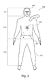
- Fig. 3 shows another exemplary embodiment of the suit system 100.
- the suit 101 in turn has the head portion 111, the upper body portion 112 and the leg portion 113 on.
- Fig. 3 is the face of the person 200 indicated to clarify that in Fig. 3 the front of the suit 101 is shown.
- the penetration of the coupling element 103 is shown.
- a closure 301 of the suit 100 which may be formed for example as a zipper.
- the closure 301 extends under the shoulders of the person 200 along the front of the suit 101.
- the closure 301 at least partially separates the suit 101 into a suit shell I and a suit base II.
- the suit 101 is not separated by the fastener 301. If the closure 301 is opened, the person 200 can pull the suit 101 over the head and put it on the back side of the person 200 (see arrow in FIG Fig. 3 ).
- the person 200 can turn the suit 101 extremely ergonomically and quickly take off.
- the person 200 can fold the suit shell I backwards and let hang down, the person 200 continues to wear the suit base II.
- the closure 300 may extend completely around the upper body region 112 so that the upper garment part I can be removed entirely from the lower garment part II.
- Fig. 4 shows the suit system 100, wherein the suit system 100 is coupled to the securing element 400.
- a penetration region 401 is also shown, in which the coupling element 103 penetrates the suit 101.
- the coupling region 401 is located in the upper body region 112 on the front side of the suit 101.
- the suit 101 in the penetration region 401 may include an additional suit material or cover (such as a flexible suit section 501 which is shown in FIG Fig. 5 shown in more detail), which Stoffumhüllung is attached to the outside of the suit 101 sealing.
- an additional suit material or cover such as a flexible suit section 501 which is shown in FIG Fig. 5 shown in more detail
- more space is created in the space around the inside of the suit 101, for example, the coupling element 103 and the coupling element of the securing band 102 and / or the seat belt 201 accommodate.
- closure 301 which under the armpits transversely from one side of the body to an opposite side of the body along the front of the suit 101 runs and separates the suit in the suit shell I and the suit base II.
- Fig. 4 the person 200 shown in a hanging position, wherein the person 200 is freely suspended in the air on the securing element 400, which is shown as a rescue rope coupled.
- the person 200 can, for example, upright her torso in the hanging position, so that in this suspended position too, freedom of movement of the arms and thus ergonomic working of the person 200 is possible.
- this hanging position as in Fig. 4 as shown the person 200 in an upright position can continue to use their hands in coordination. Further, the field of view of the person 200 is due to the illustrated hanging position in Fig. 4 continue to be directed to the hands, so that a controlled work is still possible.
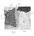
- Fig. 5 shows the suit system 100, in which a tensile force is transmitted to the coupling element 103.
- the suit 101 in Fig. 5 has the penetration area 401, through which the coupling element 103 penetrates the suit 101.
- the suit 101 has a flexible suit section 501.
- the flexible suit portion 501 can be pulled out when a tensile force is transmitted to the coupling element 103 and the coupling element 103 thus aligns with the direction of tensile force of the tensile force.
- tensions in the suit 101 are avoided because the flexible suit portion 501 expands or unfolds accordingly and compensates for the new position of the coupler 103 in the event of a tensile force transmission.
- the flexible suit section 501 has a surface on which the penetration of the coupling element 103 is formed.
- a material-bonding connection 503 (for example an adhesive connection) is used at the penetration of the coupling element 103 in order to ensure the fluid-tight passage of the coupling element 103.
- the surface of the penetration area 401 may be at a tensile force transmission spaced from a tightening surface 505 surrounding the penetration area 401 and the flexible tightening portion 501, respectively.
- the suit 101 has an edge portion 504 which surrounds and partially overlaps the flexible suit portion 501.
- the skirt portion 504 reinforces the suit 101 in the area around the flexible suit portion 501.
- the skirt portion 504 prevents unwanted unfolding of the bellows portion 502 of the flexible suit portion 501 when no tensile force is transmitted.
- the edge portion 504 thus creates a certain resistance, which prevents unfolding of the bellows-shaped portion 502 of the flexible tightening portion 501. Only when a greater tensile force is exceeded, the edge portion 504 yields, so that the bellows-shaped portion 502 of the flexible tightening portion 501 can deploy.
- the flexible suit portion 501 is formed foldable bellows or foldable. Upon transmission of the tensile force, the bellows-shaped portion 502 of the flexible tightening portion 501 unfolds so that the surface of the penetrating portion 501 is spaced from the tightening surface 505.
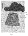
- FIG. 12 shows the exemplary embodiment of the flexible suit portion 501 according to FIG Fig. 5 , where in Fig. 6 no tensile force is transmitted via the coupling element 103.
- the flexible suit portion 501 is thus shown in a retracted state, so that the surface of the penetration area 401 is approximately on a plane like the
- Suit surface 505, which surrounds the flexible suit portion 501 is located.
- the edge portion 504 at least partially overlaps the surface of the flexible tightening portion 501.
Landscapes
- Health & Medical Sciences (AREA)
- General Health & Medical Sciences (AREA)
- Physical Education & Sports Medicine (AREA)
- Engineering & Computer Science (AREA)
- Textile Engineering (AREA)
- Business, Economics & Management (AREA)
- Emergency Management (AREA)
- Professional, Industrial, Or Sporting Protective Garments (AREA)
Abstract
Description
- Die vorliegende Erfindung betrifft ein Anzugsystem zum Sichern einer Person an einem Sicherungselement sowie ein Verfahren zum Sichern einer Person an einem Sicherungselement.
- In riskanten Einsatzgebieten, wie beispielsweise in großen Höhen, müssen Arbeiter gesichert werden, um einen Sturz abzufangen oder nach einem Unfall eine schnelle und unkomplizierte Bergung zu ermöglichen. Hierzu werden beispielsweise Sitzgurte verwendet, welche an einem Rettungsseil befestigbar sind.
- Neben der Sicherung des Arbeiters bei einem Sturz oder einem Unfall kann es in vielen Einsatzgebieten, wie beispielsweise in der Chemieindustrie, zudem notwendig sein, den Arbeiter vor einer Kontamination zu schützen. Auch beispielsweise in dem maritimen Bereich kann es erforderlich sein, den Arbeiter vor einem Eindringen eines kalten Wassers zu schützen, um eine Unterkühlung des Arbeiters zu verhindern. Aus diesem Grunde werden Anzüge, wie beispielsweise Überlebensanzüge, eingesetzt, welche den Arbeiter vor einem Eindringen eines den Anzug umgebenden Fluids (beispielsweise eines kalten Meerwassers oder toxisches Gases) schützen.
- Damit der Arbeiter bei einem Sturz gehalten und gleichzeitig gegen eine Kontamination geschützt werden kann, ist bekannt, einen Sitzgurt beispielsweise über einen fluiddichten Überlebensanzug, welcher den Arbeiter gegenüber Fluiden aus der Umgebung schützt, anzuziehen.
- Es ist eine Aufgabe der vorliegenden Erfindung, einen Anzug bereitzustellen, welcher einen Arbeiter gegenüber Einflüssen aus der Umgebung schützt und gleichzeitig vor einem Absturz sichert.
- Die Aufgabe wird mittels eines Anzugsystems zum Sichern einer Person an einem Sicherungselement und mit einem Verfahren zum Sichern einer Person an einem Sicherungselement gemäß den unabhängigen Ansprüchen gelöst.
- Gemäß einem ersten Aspekt der vorliegenden Erfindung wird ein Anzugsystem zum Sichern einer Person an einem Sicherungselement, wie z.B. einem Rettungsseil, beschrieben. Das Anzugsystem weist einen Anzug, ein Sicherungsband und ein Koppelelement auf. Der Anzug weist eine Innenseite und eine Außenseite auf. Ferner weist der Anzug einen Oberkörperbereich auf, welcher an einem Oberkörper der Person platzierbar ist.
- An der Innenseite des Anzugs ist eine Befestigungseinrichtung ausgebildet, welche das Sicherungsband an der Innenseite befestigt. Die Befestigungseinrichtung ist derart ausgebildet, dass das Sicherungsband entlang des Oberkörperbereichs verlaufend befestigt ist, so dass das Sicherungsband um den Oberkörper der den Anzug tragenden Person eine geschlossene Schlaufe bilden kann.
- Das Koppelelement durchdringt den Anzug in dem Oberkörperbereich derart, dass der Anzug an der Durchdringung mittels des Koppelelements fluiddicht ist, d.h., dass zwischen dem Koppelelement und dem Anzug kein Fluid (Gas, Flüssigkeit) von der Umgebung des Anzugs in ein Innenvolumen des Anzugs eindringbar ist.
- Das Koppelelement ist einerseits mit dem Sicherungsband gekoppelt und andererseits mit dem Sicherungselement koppelbar, so dass eine lasttragende Verbindung zwischen dem Sicherungsband und dem Sicherungselement herstellbar ist.
- Gemäß einem weiteren Aspekt der vorliegenden Erfindung wird ein Verfahren zum Sichern einer Person an einem Sicherungselement beschrieben. Gemäß dem Verfahren wird ein Oberkörperbereich eines Anzugs an einem Oberkörper der Person platziert. An einer Innenseite des Anzugs ist eine Befestigungseinrichtung ausgebildet, welche ein Sicherungsband an der Innenseite befestigt, wobei die Befestigungseinrichtung derart ausgebildet ist, dass das Sicherungsband entlang des Oberkörperbereichs verlaufend befestigt ist. Ferner wird eine geschlossene Schlaufe des Sicherungsbands gebildet, so dass das Sicherungsband um den Oberkörper der den Anzug tragenden Person verläuft. Ein Koppelelement wird mit dem Sicherungsband gekoppelt, wobei das Koppelelement den Anzug in dem Oberkörperbereich derart durchdringt, dass der Anzug an der Durchdringung mittels des Koppelelements fluiddicht ist. Das Koppelelement ist mit dem Sicherungselement koppelbar, so dass eine lasttragende Verbindung zwischen dem Sicherungsband und dem Sicherungselement herstellbar ist.
- Als Anzug wird im Folgenden ein Überlebensanzug bzw. ein Schutzanzug verstanden, welcher von der zu sichernden Person getragen werden kann. Der Anzug besteht beispielsweise aus einem robusten natürlichem oder künstlichem Stoff bzw. Gewebe. Das Material des Anzugs ist derart gewählt, dass ein den Anzug umgebendes Fluid, wie beispielsweise eine Flüssigkeit oder ein Gas, nicht durch das Material (bzw. die Anzugmembran) in das Innere des Anzugs eindringen kann. Der Anzug kann als Overall bzw. Ganzanzug ausgebildet sein. Als Ganzanzug weist der Anzug beispielsweise einen Oberkörperbereich und einen Beinbereich auf, so dass der Oberkörper sowie die Beine der Person in dem Anzug platziert und eingehüllt werden können. Ferner weist der Oberkörperbereich Armbereiche auf, welche die Arme der zu sichernden Person umhüllen. Um die Dichtigkeit des Anzugs zu gewährleisten, können an Öffnungen des Anzugs, wie beispielsweise an einem Kopfbereich, an einem Armbereich oder an einem Fußbereich des Anzugs entsprechende Hauben, Handschuhe oder Schuhe dichtend befestigt werden.
- Als Sicherungselement wird ein Element verstanden, an welchem die Person zur Sicherung oder zur Bergung mittels des Koppelelements befestigt werden kann. Das Sicherungselement ist ausgebildet um zumindest das Gewicht der Person zu tragen. Das Sicherungselement kann beispielsweise eine Laufschiene, ein Geländer, ein Karabinerhaken oder ein Sicherungsseil sein, welches mit einem Ende an dem Koppelement und mit dem anderen Ende an einem festen Fundament (z.B. an einer Seilwinde oder an der Laufschiene) befestigt sein kann.
- An der Innenseite des Anzugs ist die Befestigungseinrichtung ausgebildet, welche das Sicherungsband an der Innenseite befestigt. Die Befestigungseinrichtung kann beispielsweise aus mehreren voneinander beabstandeten Laschen bestehen, durch welche das Sicherungsband geführt werden kann. Insbesondere ist die Befestigungseinrichtung derart ausgebildet, dass das Sicherungsband eine geschlossene Schlaufe um den Oberkörper der Person bilden kann. Das Sicherungsband ist mittels der Befestigungseinrichtung sozusagen fest im Anzug an der Innenseite befestigt. Aufgrund der Befestigung des Sicherungsbandes in einer Lasche bzw. in einem Tunnel, welche an der Innenseite des Anzugs befestigt sind und die Befestigungseinrichtung bilden, kann das Sicherungsband austauschbar mit dem Anzug befestigt werden, so dass das Sicherungsband beispielsweise für eine Inspektion und einem Austausch entnehmbar ist.
- Die geschlossene Schlaufe wird insbesondere in einer Ebene bereitgestellt, welche im Wesentlichen parallel zu einer Standfläche verläuft, auf welcher die Person aufrecht steht. Mit anderen Worten verläuft die Schlaufe an der Innenseite des Anzugs derart, dass eine den Anzug tragende Person die Schlaufe unterhalb der Achseln und oberhalb der Beine trägt, so dass das Sicherungsband von einem Brustbereich unterhalb eines Achselbereichs zu einem Rückenbereich verläuft und von dem Rückenbereich unterhalb des weiteren Achselbereichs wieder zu dem Brustbereich verläuft. Mit anderen Worten verläuft das Sicherungsband rundherum um den Oberkörperbereich und unter den Achseln einer den Anzug tragenden Person.
- Das Sicherungsband kann beispielsweise ein flaches Band mit einer hohen Reißfestigkeit darstellen. Das Sicherungsband kann sich mit seiner flachen Oberfläche ergonomisch an den Oberkörper der den Anzug tragenden Person anschmiegen. Ferner kann das Sicherungsband auch in einer Seilform mit einem runden Querschnitt ausgebildet werden.
- An einem Koppelabschnitt ist das Sicherungsband mit dem Koppelelement gekoppelt. Das Koppelelement ist beispielsweise ein robuster Bolzen, welcher den Anzug durchdringt und von der Außenseite des Anzugs in die Umgebung ragt und gleichzeitig von der Innenseite des Anzugs in das Innenvolumen des Anzugs hineinragt. An den jeweiligen Enden des Koppelelements im Bereich der Innenseite oder der Außenseite des Anzugs kann das Koppelelement Befestigungselemente aufweisen, um entsprechend mit dem Sicherungsband oder dem Sicherungselement gekoppelt zu werden. Die Befestigungselemente sind beispielsweise Haken oder Ösen, an welchen beispielsweise ein Karabinerhaken oder andere lastübertragende Vorkehrungen befestigbar sind.
- Im Bereich der Durchdringung des Koppelelements durch den Anzug kann das Koppelelement Dichtelemente, wie beispielsweise Dichtlamellen zur Abdichtung des Anzugs aufweisen. Ferner kann das Koppelelement im Bereich der Durchdringung flanschartige bzw. scheibenförmige Bereiche aufweisen, welche mit der Innenseite und/oder der Außenseite des Anzugs einen Flächenkontakt bilden, so dass eine bessere Dichtwirkung erreicht werden kann. Im Bereich der Durchdringung kann das Koppelelement ferner eine stoffschlüssige Verbindung aufweisen. Die stoffschlüssige Verbindung zwischen dem Koppelelement und dem Anzug kann beispielsweise mittels Verlötens, Schweißens, Klebens oder Vulkanisierens zwischen dem Koppelelement und dem Anzug erzielt werden. Das Koppelelement kann ferner fluiddicht und belastbar an der Durchdringung mit dem Anzug befestigt werden, indem das Koppelelement beispielsweise über einen geschraubten Klemmflansch und/oder über eine grobflächige Flanschanklebung mit dem Anzug bzw. der Anzugmembrane befestigt wird.
- Mittels der oben beschriebenen Erfindung wird ein Anzugsystem bereitgestellt, in welchem eine Fallsicherung/Bergungssicherung integriert ist und gleichzeitig ein Kontaminationsschutz gegeben ist. Zudem verlaufen alle zur Sicherung der Person benötigten Elemente, wie beispielsweise das Sicherungsband, in einem geschützten Innenvolumen des Anzugs, so dass die Sicherungselemente nicht von einem sich in der Umgebung befindenden Fluid kontaminiert werden.
- Da in dem Anzugsystem alle zur Sicherung notwendigen Elemente in dem Anzug integriert sind, benötigt die zu sichernde Person nicht zwingend zusätzliche Sicherungselemente, wie beispielsweise einen Sitzgurt, so dass durch Tragen des Anzugsystems alleine bereits ein Fallschutz bereitgestellt wird. Insbesondere in Einsatzbereichen, in welchen das Tragen eines Sicherungsgurts nicht zwingend vorgeschrieben ist, erhöht das Anzugsystem die Arbeitssicherheit enorm. Gelangt eine Person überraschenderweise in eine Notsituation, beispielsweise da die Person über Bord eines Schiffes gegangen ist, so kann aufgrund des integrierten Sicherungsbandes und des Koppelelements des Anzugsystems eine sichere und schnelle Bergung der Person ermöglicht werden, auch wenn diese keinen Sitzgurt trägt.
- Da das Sicherungsband entlang der Innenseite des Anzugs verläuft, stellt dies keine Beeinträchtigung der Person während des Tragens des Anzugsystems dar. Das Sicherungsband wird solange z.B. keine Zugkraft des Sicherungselements (z.B. des Rettungsseils) über das Koppelelement übertragen wird locker um den Oberkörper der Person getragen. Erst wenn das Koppelelement an dem Sicherungselement angehängt ist und eine Zugkraft von dem Sicherungselement auf das Koppelelement übertragen wird, spannt sich die Schlaufe des Sicherungsbands um die Person. Bei Zug z.B. des Rettungsseils wird die Gewichtskraft der Person über das Sicherungsband und dem Koppelelement auf das Rettungsseil übertragen. Das Sicherungsband schmiegt sich bei Zug an den Oberkörper der Person an. Insbesondere, da das Sicherungsband unterhalb der Achseln der Person um den Oberkörper in der geschlossenen Schlaufe verläuft, wird ein Herausrutschen der Person aus der Schlaufe des Sicherungsbandes verhindert. Somit kann die Person gesichert werden, auch wenn diese keinen Sitzgurt oder weitere Sicherungsmittel, wie beispielsweise weiteres Sicherungsgeschirr, am Körper trägt.
- Gemäß einer weiteren beispielhaften Ausführungsform durchdringt das Koppelelement einen Vorderbereich des Oberkörperbereichs des Anzugs. Der Vorderbereich kann einen Brustbereich der den Anzug tragenden Person abdecken. Da das Koppelelement den Vorderbereich des Oberkörperbereichs des Anzugs durchdringt, kann die Person selbst in einfacher Art und Weise das Sicherungselement an dem Koppelelement befestigen, da der Vorderbereich des Anzugs im Blickfeld und im Greifbereich der Person liegt. Ferner ist die Kraftübertragung von dem Koppelelement auf das Sicherungselement in dem Vorderbereich des Oberkörperbereichs ergonomischer als eine Übertragung der Zugkraft des Sicherungselements auf ein Koppelelement, welches beispielsweise einen Rückenbereich des Oberkörperbereichs des Anzugs durchdringt.
- Gemäß einer weiteren beispielhaften Ausführungsform weist die Befestigungseinrichtung ein schlauchförmiges Element (z.B. ein schlauchartiges Gewebe) auf, wobei das schlauchförmige Element an der Innenseite des Anzugs befestigt ist. Das Sicherungsband wird innerhalb des schlauchförmigen Elements zur Befestigung an der Innenseite des Anzugs angeordnet. Das schlauchförmige Element bildet mit anderen Worten einen Tunnel bzw. einen Kanal aus, welcher kontinuierlich oder in kurzen Abständen über Befestigungspunkte oder -nähte an der Innenseite des Anzugs befestigt ist, beispielsweise mittels eines reißfesten Garns oder mittels einer stofflichen Verbindung, wie beispielsweise mittels einer Klebeverbindung. Da das schlauchförmiges Element das Sicherungsband umhüllt und eine geschlossenen Tasche um das Sicherungsband bildet, verringert sich das Risiko, dass die Person beim Anziehen des Anzugs zwischen dem Sicherungsband und der Innenseite des Anzugs verkeilt. Somit werden das Anziehen und das Ausziehen des Anzugs erleichtert. Zudem findet eine schonendere Kraftübertragung zwischen dem Sicherungsband, dem Anzug und der Person statt, da das Sicherungsband nicht nur über wenige im Abstand voneinander angeordnete Befestigungselemente, z.B. voneinander beabstandete Laschen, an der Innenseite befestigt ist, sondern über eine gesamte Länge des schlauchförmigen Elements die Kraft zwischen dem Sicherungsband und dem Anzug überträgt. Das schlauchförmige Element kann nahezu vollständig das Sicherungsband der Länge nach einhüllen. Lediglich an dem Koppelabschnitt des Sicherungsbandes mit dem Koppelelement ist das Sicherungsband frei von dem schlauchartigen Gewebe, so dass eine direkte Kopplung zwischen dem Sicherungsband und dem Koppelelement ermöglicht wird.
- Das schlauchförmige Element kann z.B. aus einem reißfesten Natur- oder Kunstgarn gewebt sein. Ferner kann in dem schlauchförmigen Element ein Polsterelement angeordnet werden, so dass eine sanftere Kraftübertragung zwischen dem Sicherungsband und der Person bereitgestellt wird. Insbesondere, wenn eine Zugkraft des Sicherungselements auf das Sicherungsband und somit auf die Person übertragen wird, können Einschnürungen an dem Körper der Person durch die Polsterelemente reduziert bzw. verhindert werden.
- Gemäß einer weiteren beispielhaften Ausführungsform ist die Befestigungseinrichtung ferner an der Innenseite des Anzugs derart ausgebildet, dass die Befestigungseinrichtung einen zusätzlichen Abschnitt des Sicherungsbandes z.B. um einen weiteren Bereich, z.B. einen Beinbereich, des Anzugs befestigt. Neben der durch das Sicherungsband gebildeten und geschlossenen Schlaufe um den Oberkörper der Person kann zur besseren Kraftverteilung einer eingeleiteten Zugkraft der zusätzliche Abschnitt des Sicherungsbandes um den Beinbereich des Anzugs verlaufen. Der zusätzliche Abschnitt verläuft an der Person bei Tragen des Anzugs somit beispielsweise ausgehend von einem vorderen Bereich der geschlossenen Schlaufe des Sicherungsbandes zu dem vorderen Beckenbereich einer Person, weiter zwischen den Beinen der Person und weiter entlang des Gesäßes der Person zurück zu einem hinteren Bereich bzw. zu einem Rückenbereich der geschlossenen Schlaufe des Sicherungsbandes. Ferner kann ein weiterer zusätzlicher Abschnitt des Sicherungsbandes einen Oberschenkelbereich des Anzugs, welcher den Oberschenkel einer den Anzug tragenden Person abdeckt, umlaufen, so dass eine weitere geschlossene Schlaufe um den Oberschenkel der Person gebildet wird. Somit kann eine vorteilhafte und sanftere Krafteinleitung zwischen der Person und dem Sicherungsband bei Übertragung einer Zugkraft des Sicherungselements ermöglicht werden. Gemäß einer weiteren beispielhaften Ausführungsform weist das Anzugsystem einen Sitzgurt auf, welcher zwischen der Innenseite des Anzugs und der den Anzug tragenden Person anordbar ist und an dieser befestigbar ist. Der Sitzgurt weist ein Befestigungselement (z.B. Hacken, Öse oder Karabiner) auf, wobei das Befestigungselement an dem Sicherungsband und/oder dem Koppelelement befestigbar ist, um eine weitere lasttragende Verbindung zwischen dem Sicherungsband und dem Sitzgurt bereitzustellen. Mit dem oben beschriebenen Ausführungsbeispiel kann das Anzugsystem einerseits ohne Sitzgurt oder mit Sitzgurt verwendet werden. Ist der Arbeitsbereich der Person beispielsweise in großen Höhen vorgesehen, so dass eine permanente Sicherung der Person notwendig ist, so kann die Person einen Sitzgurt und weiteres Sicherungsgeschirr bei sich tragen und über das Sicherungsband und dem Koppelelement an das Sicherungselement (z.B. Rettungsseil, Laufschiene etc.) koppeln. Ein Sitzgurt ist insbesondere zum permanenten freischwebenden Halten einer Person vorgesehen, so dass dieser äußerst ergonomisch die Kräfte von der Person auf das Rettungsseil und umgekehrt überträgt.
- Ferner kann eine lösbare Verbindung zwischen dem Sitzgurt (bzw. Auffanggurt) und dem Sicherungsband vorgesehen werden, so dass der Anzug abgelegt werden kann, ohne den Sitzgurt ablegen zu müssen. Der Sitzgurt und das Sicherungsband sind aufgrund der inneren Position zwischen dem Anzug und der Person gegen äußere Einflüsse, wie beispielsweise gegen kaltes Wasser, insbesondere gegen aggressives, salzhaltiges Seewasser oder anderen toxischen Fluiden in der Umgebung geschützt. Da der Auffanggurt und der Sicherungsgurt z.B. über einen gemeinsamen Koppelpunkt, beispielsweise an der Kopplung zwischen dem Sicherungsband und dem Sitzgurt, gekoppelt sind, finden keine gegenseitigen Beeinträchtigungen in der Schutzwirkung der einzelnen Anzugkomponenten, insbesondere zwischen dem Anzug, dem Sicherungsband und dem Sitzgurt statt.
- Wird die Durchdringung des Koppelelements an einer integrierten zentrale Position in Brusthöhe des Anzugs vorgesehen und wird in dieser zentralen Position (auch Anschlagpunkt bezeichnet) das Sicherungsband und/oder der Sitzgurt an das Koppelelement befestigt, kann eine effiziente Krafteinleitung des Sitzgurts auf das Sicherungsband und somit dem Anzug bereitgestellt werden. Ferner kann die Person eine hängende oder sitzende Position einnehmen oder beispielsweise ein Gefälle auf- und absteigen, ohne dass eine Behinderung aufgrund des Koppelelements und der daran gekoppelten Elemente (z.B. Sicherungselement) verursacht werden.
- Gemäß einer weiteren beispielhaften Ausführungsform weist das Sicherungsband einen Koppelabschnitt auf, wobei innerhalb des Koppelabschnitts das Koppelelement und das Befestigungselement des Sitzgurts an das Sicherungsband angekoppelt sind. Beispielsweise kann das Sicherungsband auf der einen Seite des Koppelabschnitts eine Vorkehrung zur Kopplung des Koppelelements aufweisen und auf einer gegenüberliegenden anderen Seite des Koppelabschnitts eine weitere Vorkehrung aufweisen, an welcher das Befestigungselement des Sitzgurts angekoppelt ist. Somit wird nahezu eine direkte Kraftübertragung zwischen dem Befestigungselement des Sitzgurts und dem Koppelelement hergestellt.
- Gemäß einer weiteren beispielhaften Ausführungsform weist das Anzugsystem einen Verschluss zum Verschließen und Öffnen auf, wobei der Verschluss entlang des Oberkörperbereichs derart verläuft, dass der Verschluss den Anzug in ein Anzugoberteil z.B. mit Armbereichen und in ein Anzugunterteil z.B. mit Beinbereichen zumindest teilweise trennt. Der Verschluss kann beispielsweise ein Reißverschluss sein, welcher fluiddicht ausgebildet ist, so dass durch den geschlossenen Verschluss kein Fluid von außen in den Anzug eindringen kann.
- Insbesondere trennt der Verschluss den Anzug in das Anzugoberteil und das Anzugunterteil. Mit anderen Worten trennt der Verschluss den Anzug entlang einer im Wesentlichen horizontalen Ebene, wenn die Person mit dem Anzug aufrecht in einer vertikalen Position steht. Beispielsweise kann der Verschluss ausschließlich entlang der Vorderseite des Anzugs verlaufen und der Anzug kann auf der Rückseite durchgängig verarbeitet sein und keinen Verschluss aufweisen. Bei Öffnen des Verschlusses kann die Person beispielsweise die Arme durch die Verschlussöffnung hindurchstecken und die Vorderseite des Anzugs über den Kopf der Person nach hinten, in Richtung des Rückens der Person ausziehen. Diese Anbringung des Verschlusses an dem Anzug erhöht im Vergleich zu einem Verschluss entlang einer Vertikalebene ein ergonomisches An- und Ausziehen des Anzugs. Ferner kann bei Anbringung des Verschlusses entlang der Horizontalebene eine große durchgängige Anzugfläche auf der Vorderseite des Anzugs im Anzugoberteil geschaffen werden, so dass zentral an der Vorderseite des Anzugoberteils die Durchdringung des Koppelelements bereitstellbar ist, ohne dass in der Nähe des Durchdringungspunktes der Verschluss verläuft. Ein Verlauf des Verschlusses in unmittelbarer Umgebung kann die Festigkeit des Anzugs reduzieren.
- Ferner kann durch den horizontalen Verlauf des Verschlusses das Anzugoberteil bei physisch anstrengenden Arbeiten der Person einfach nach hinten geklappt werden, so dass der Oberkörper der Person frei ist und eine Überhitzung der den Anzug tragenden Person reduziert werden kann. Der Verschluss kann beispielsweise nach Art eines Känguru-Verschlusses ausgebildet sein.
- Gemäß einer weiteren beispielhaften Ausführungsform ist die Schlaufe des Sicherungsbandes mit einem wiederverschließbaren Schnellverschluss, insbesondere mit einem Klickverschluss, schließbar. Die Schlaufe des Sicherungsbandes kann somit geöffnet und geschlossen vorliegen. Ist das Sicherungsband geöffnet, kann die Person ergonomisch und effizient den Anzug an- und ausziehen, ohne sich durch die enge geschlossenen Schlaufe des Sicherungsbandes zwängen zu müssen. In dem geöffneten Zustand des Sicherungsbandes kann die Person einfach den Anzug anziehen, ohne dass das Sicherungsband das Anziehen des Anzugs behindert. Nachdem die Person den Anzug angezogen hat, beispielsweise nachdem die Person den Kopf durch eine Kopföffnung am Anzug, die Arme durch Armöffnungen am Anzug und die Beine durch Beinöffnungen am Anzug hindurchgesteckt hat, kann die Person die Schlaufe mittels des wiederverschließbaren Schnellverschlusses schließen. Das Sicherungsband kann anschließend in lösbarer Art und Weise an dem Koppelelement gekoppelt werden. Das Koppelelement kann auch in einer Ausführungsform permanent und integral mit dem Koppelelement befestigt sein.
- Der Schnellverschluss kann beispielsweise mit einem Klickverschluss oder mit einem anderen festen und robusten wiederverschließbaren Verschluss ausgebildet sein.
- Gemäß einer weiteren beispielhaften Ausführungsform des Verfahrens wird ein Sitzgurt an der Person befestigt. Der Sitzgurt wird zwischen der Innenseite des Anzugs und der den Anzug tragenden Person angeordnet und an dieser befestigt. Ein Befestigungselement des Sitzgurts wird an einem Koppelabschnitt des Sicherungsbandes und/oder direkt an dem Koppelelement befestigt, um eine weitere lasttragende Verbindung zwischen dem Sicherungsband und/oder dem Koppelelement und dem Sitzgurt bereitzustellen. In dem Koppelabschnitt ist das Koppelelement mit dem Sicherungsband gekoppelt.
- Ferner kann in dem Anzug ein Rückenpolster eingearbeitet sein, welches entlang des Rückens einer den Anzug tragenden Person verläuft. Am oberen Ende des Rückenpolsters kann eine Halskrause zur Stützung des Halsbereichs der den Anzug tragenden Person eingearbeitet sein. Das Rückenpolster kann beispielsweise mit dem Sicherungsband in einer kraftübertragenden Verbindung stehen, so dass eine bessere Kraftverteilung zwischen der Person und dem Sicherungsband bereitgestellt wird, da über eine größere Fläche, nämlich über das Sicherungsband und der Fläche des Rückenpolsters, eine Kraftübertragung auf das Koppelelement stattfinden kann.
- Gemäß einer weiteren beispielhaften Ausführungsform weist der Anzug einen flexiblen Anzugabschnitt auf. Der Anzug weist in dem flexiblen Anzugabschnitt einen Durchdringungsbereich auf, in welchem das Koppelelement den Anzug durchdringt. Der flexible Anzugabschnitt ist derart ausgebildet, dass bei Übertragung einer Zugkraft auf das Koppelelement ein Teil des flexiblen Anzugabschnitts zusammen mit dem Koppelelement relativ zu einer Anzugoberfläche des Anzugs, welche den flexiblen Anzugabschnitt umgibt, bewegbar ist.
- Die Zugkraft wird beispielsweise über das Koppelelement auf das Sicherungsband übertragen, wenn die Person an einem Rettungsseil hängt. Wird die Zugkraft über das Koppelelement auf das Sicherungsband übertragen, so richten sich das Koppelelement und das Sicherungsband in Richtung der Zugkraftrichtung aus. Durch das Verschieben bzw. das Ausrichten des Koppelelements und des Sicherungsbands kann es zu Spannungen des Anzugs kommen, so dass ein Teil der Zugkraft über den Anzug übertragen wird. Dies kann zu einer Rissbildung in dem Anzug führen.
- Um zu verhindern, dass ein Teil der Zugkraft von dem Koppelelement auf den Anzug übertragen wird, wird der oben beschriebene flexible Anzugabschnitt um den Durchdringungsbereich ausgebildet. Kommt es bei einem Verschieben des Koppelelements während der Zugkraftübertragung zu einer Spannung im Anzug, so gibt der flexible Anzugabschnitt nach, bis das Koppelelement und der Anzug derart ausgerichtet sind, dass die Zugkraft ausschließlich über das Koppelelement in das Sicherungsband übertragen wird. Dieser Ausgleich kann insbesondere dadurch geschaffen werden, indem der flexible Anzugabschnitt sich relativ zur Anzugoberfläche bewegen, z.B. ausdehnen, kann, so dass in dem ausgedehnten Zustand des flexiblen Anzugabschnitts der Durchdringungsbereich beabstandet von der Anzugoberfläche vorliegt.
- Der flexible Anzugabschnitt kann in einer beispielhaften Ausführungsform mittels eines elastisch verformbaren Materials ausgebildet werden. Tritt beispielsweise die Verschiebung des Koppelelements relativ zu der Anzugoberfläche bei einer Übertragung der Zugkraft auf, so dehnt sich entsprechend der flexible Anzugabschnitt bzw. sein Material aus. Wird keine Zugkraft über das Koppelelement übertragen, so zieht sich der flexible Anzugabschnitt entsprechend zusammen und tritt nicht bzw. kaum von der Anzugoberfläche hervor.
- Diese Funktionalität des flexiblen Anzugabschnitts kann in einer weiteren beispielhaften Ausführungsform dadurch bereitgestellt werden, indem der flexible Anzugabschnitt balgförmig faltbar ausgebildet ist, so dass bei der Übertragung der Zugkraft auf das Koppelelement der flexible Anzugabschnitt von einer Anzugoberfläche balgförmig ausfahrbar bzw. entfaltbar ist, so dass der Durchdringungsbereich bzw. ein Oberflächenbereich des flexiblen Anzugabschnitts beabstandet von der Anzugoberfläche vorliegt.
- Wird keine Zugkraft von dem Koppelelement übertragen, liegt der flexible Anzugabschnitt beispielsweise zusammengefaltet vor, so dass die Oberfläche des Durchdringungsbereichs in derselben Ebene wie die Anzugoberfläche vorliegt, welche den flexiblen Anzugabschnitt umgibt.
- Der flexible Anzugabschnitt bildet sozusagen eine Balgtasche aus, welche in einem ausgefalteten Zustand ein zusätzliches Volumen zwischen dem Träger des Anzugs und dem Durchdringungsbereich erzeugt.
- Gemäß einer weiteren beispielhaften Ausführungsform weist der Anzug einen Randabschnitt auf, welcher den flexiblen Anzugabschnitt zumindest teilweise überlappt, insbesondere wenn das Koppelelement und der flexible Anzugabschnitt zugkraftfrei sind.
- Der Randabschnitt bildet beispielsweise einen überlappenden Abschnitt aus, welcher den flexiblen Anzugabschnitt überlappt. Der Randabschnitt ist sozusagen eine Art Patte, welche den flexiblen Anzugsabschnitt zumindest teilweise überlappt. Insbesondere liegt die Überlappung des Randabschnitts mit dem flexiblen Anzugabschnitt vor, wenn die Oberfläche des Durchdringungsbereichs ungefähr in einer Ebene mit der Anzugoberfläche, welche den Durchdringungsbereich umgibt, vorliegt. Der Randabschnitt schützt den flexiblen Anzugabschnitt vor äußeren einflüssen. Ferner verhindert der Randabschnitt z.B. ein ungewolltes Entfalten des balgförmigen flexiblen Anzugabschnitts, wenn keine Zugkraft übertragen wird. Der Randabschnitt erzeugt somit einen gewissen Widerstand, welcher ein Entfalten des balgförmigen flexiblen Anzugabschnitts verhindert. Erst bei Überschreiten einer größeren Zugkraft gibt der Randabschnitt nach, so dass der flexible Anzugabschnitt sich entfalten kann.
- Gemäß einer weiteren beispielhaften Ausführungsform weist das Koppelelement an der fluiddichten Durchdringung des Anzugs eine stoffschlüssige Verbindung zwischen dem Koppelelement und dem Anzug auf. Die stoffschlüssige Verbindung kann beispielsweise eine Lötverbindung, eine Schweißverbindung, eine Klebverbindung oder eine vulkanisierte Verbindung aufweisen. Mit anderen Worten kann die stoffschlüssige Verbindung mittels Lötens, mittels Schweißens, mittels Klebens oder mittels Vulkanisierens hergestellt werden.
- Die dichtende Verbindung zwischen dem Koppelelement und dem Durchdringungsbereich des Anzugs kann beispielsweise auch über einen Klemmflansch bereitgestellt werden, wobei beispielsweise an einer Innenseite des Anzugs eine erste Platte und an einer Außenseite des Anzugs eine zweite Platte anliegt, wobei zwischen den Platten der Durchdringungsbereich des Anzugs und eine entsprechend vorgesehene Auskragung des Koppelelement zusammengespannt werden kann. Somit wird eine mechanische, dichtende Verbindung zwischen dem Koppelelement und dem Durchdringungsbereich des Anzugs hergestellt.
- Es wird darauf hingewiesen, dass Ausführungsformen der Erfindung mit Bezug auf unterschiedliche Erfindungsgegenstände beschrieben wurden. Insbesondere sind einige Ausführungsformen der Erfindung mit Vorrichtungsansprüchen und andere Ausführungsformen der Erfindung mit Verfahrensansprüchen beschrieben. Dem Fachmann wird jedoch bei der Lektüre dieser Anmeldung sofort klar werden, dass, sofern nicht explizit anders angegeben, zusätzlich zu einer Kombination von Merkmalen, die zu einem Typ von Erfindungsgegenstand gehören, auch eine beliebige Kombination von Merkmalen möglich ist, die zu unterschiedlichen Typen von Erfindungsgegenständen gehören.
- Im Folgenden werden zur weiteren Erläuterung und zum besseren Verständnis der vorliegenden Erfindung Ausführungsbeispiele unter Bezugnahme auf die beigefügten Zeichnungen näher beschrieben. Es zeigen:
-
Fig. 1 eine schematische Darstellung des Anzugsystems gemäß einer beispielhaften Ausführungsform der vorliegenden Erfindung; -
Fig. 2 eine schematische Darstellung des Anzugsystems, welches von einer Person getragen wird, gemäß einer beispielhaften Ausführungsform der vorliegenden Erfindung; -
Fig. 3 eine schematische Darstellung des Anzugsystems mit einem Verschluss gemäß einer beispielhaften Ausführungsform der vorliegenden Erfindung; -
Fig. 4 eine schematische Darstellung des Anzugsystems, wobei das Anzugsystem an einem Koppelelement eines Rettungsseils befestigt ist; -
Fig. 5 ein Anzugsystem mit einem flexiblen Anzugabschnitt, bei welchem eine Zugkraft auf das Koppelelement übertragen wird, gemäß einer beispielhaften Ausführungsform der vorliegenden Erfindung; und -
Fig. 6 ein Anzugsystem, bei welchem keine Zugkraft auf das Koppelelement übertragen wird, gemäß einer beispielhaften Ausführungsform der vorliegenden Erfindung. - Gleiche oder ähnliche Komponenten in unterschiedlichen Figuren sind mit gleichen Bezugsziffern versehen. Die Darstellungen in den Figuren sind schematisch.
-
Fig. 1 zeigt ein Anzugsystem 100 zum Sichern einer Person 200 (sieheFig. 2 ) an einem Sicherungselement 400 (sieheFig. 4 ). Das Anzugsystem 100 weist einen Anzug 101, ein Sicherungsband 102 und ein Koppelelement 103 auf. Der Anzug 101 weist einen Kopfbereich 111, einen Oberkörperbereich 112 und einen Beinbereich 113 auf. - Der Kopfbereich 111 umfasst beispielsweise eine Haube oder einen Kopfüberzug, so dass der Kopf einer Person 200 beispielsweise gegenüber einem Fluid aus der Umgebung des Anzugs 101 geschützt werden kann. In dem Kopfbereich 111 kann beispielsweise ebenfalls ein Beatmungsgerät oder ähnliches angeschlossen oder integriert werden. Der Oberkörperbereich 112 beschreibt beispielsweise den Bereich des Anzugs 101, welcher die Arme, den Brustbereich und den Bauchbereich einer den Anzug 101 tragenden Person 200 einhüllt und abdeckt. Der Beinbereich 113 deckt beispielsweise die Hüfte und beide Beine der den Anzug tragenden Person 200 ab.
- An der Innenseite des Anzugs 101 ist eine Befestigungseinrichtung ausgebildet, welche das Sicherungsband 102 an der Innenseite befestigt, wobei die Befestigungseinrichtung derart ausgebildet ist, dass das Sicherungsband 102 entlang des Oberkörperbereichs 112 verlaufend befestigt ist, so dass das Sicherungsband 102 um den Oberkörper und unter den Achseln der den Anzug 101 tragenden Person 200 eine geschlossene Schlaufe bilden kann. Ein Koppelelement 103, wie beispielsweise ein Bolzen, durchdringt den Anzug 101 im Oberkörperbereich 112 derart, dass der Anzug 101 an der Durchdringung mittels des Koppelelements 103 fluiddicht ist.
- Beispielsweise kann das Koppelelement 103 einen Flanschbereich im Bereich der Durchdringung des Anzugs 101 aufweisen, so dass an der Innenseite oder an der Außenseite eine große Auflagefläche mit dem Flansch des Koppelelements 103 bereitstellbar ist. Die große Auflagefläche verbessert beispielsweise eine Klebeverbindung des Koppelelements 103 mit dem Stoff des Anzugs 101.
- Das Koppelelement 103 ist einerseits mit dem Sicherungsband 102 gekoppelt und andererseits mit dem Sicherungselement 400, wie z.B. einem Rettungsseil oder einer Laufschiene, koppelbar. Dadurch wird eine lasttragende Verbindung zwischen dem Sicherungsband 102 und dem Rettungsseil 400 hergestellt.
- Das Sicherungsband 102 bildet eine geschlossene Schlaufe um den Oberkörper der den Anzug tragenden Person 200, so dass mittels der Schlaufe eine Person 200 in dem Anzug 101 an das Sicherungselement 400 angehängt werden kann, ohne dass die Person 200 zusätzlich Sicherungsvorrichtungen, wie beispielsweise einen Sitzgurt oder anderes Sicherungsgeschirr, zwingend tragen muss.
- In
Fig. 1 wird der Verlauf des Sicherungsbandes 102 gestrichelt dargestellt, um zu verdeutlichen, dass das Sicherungsband 102 entlang einer Innenseite des Anzugs 101 verläuft. -
Fig. 2 zeigt das Anzugsystem 100 einschließlich einer das Anzugsystem 100 tragenden Person 200 (gestrichelte Linien). Ferner ist inFig. 2 das Gesicht der Person 200 dargestellt um zu verdeutlichen, dass inFig. 2 die Vorderseite der Person 200 und des Anzugs 101 dargestellt ist. - Im Brustbereich der Person 200, welche durch den Oberkörperbereich 112 des Anzugs 101 abgedeckt wird, verläuft das Sicherungsband 102 unter den Achseln und um den Oberkörper der Person 200. Im Brustzentrum bzw. an der Vorderseite des Oberkörperbereichs 112 des Anzugs 101 ist das Koppelelement 103 mit dem Sicherungsband 102 gekoppelt. Ferner befindet sich an dieser Position die Durchdringung des Koppelelements 103 durch den Anzug 101. Somit kann die Person 200 an das Sicherungselement 400 angekoppelt werden und in einer sitzenden oder hängenden Position mittels des Rettungselements 400 (z.B. des Sicherungsseils) geborgen werden. Ferner stört eine Kopplung des Sicherungselements 400 mit dem in dem Brustzentrum angeordneten Koppelelement 103 nicht die Person 200 beispielsweise während des Laufens oder des Steigens.
- Zusätzlich kann wie in
Fig. 2 dargestellt die Person 200 optional einen Sitzgurt 201 tragen. Der Sitzgurt 201 umschließt beispielsweise die Beine der Person 200 und den Beckenbereich der Person 200. Zudem ist der Sitzgurt 201 mit einem Befestigungselement (wie beispielsweise einem Karabinerhaken, einem Haken oder einer Klickverbindung) mit einem Koppelabschnitt des Sicherungsbandes 102 oder direkt mit dem Koppelelement 103 gekoppelt. Der Sicherungsgurt 201 ermöglicht eine ergonomische Kraftübertragung des Körpergewichts der Person 200 auf das Sicherungselement 400, so dass beispielsweise die Person 200 über einen längeren Zeitraum in einer Hängeposition, bei welcher die Person 200 an dem Sicherungselement 400 hängt, arbeiten kann ohne Ermüdungserscheinungen und Erschöpfungserscheinungen aufgrund des Hängens zu verspüren. -
Fig. 3 zeigt eine weitere beispielhafte Ausführungsform des Anzugsystems 100. Der Anzug 101 weist wiederum den Kopfbereich 111, den Oberkörperbereich 112 und den Beinbereich 113 auf. InFig. 3 ist das Gesicht der Person 200 angedeutet, um zu verdeutlichen, dass inFig. 3 die Vorderseite des Anzugs 101 dargestellt wird. Im Brustbereich bzw. auf der Vorderseite des Anzugs 101 ist die Durchdringung des Koppelelements 103 dargestellt. - Ferner zeigt
Fig. 3 einen Verschluss 301 des Anzugs 100, welcher beispielsweise als Reißverschluss ausgebildet sein kann. Der Verschluss 301 verläuft unter den Achseln der Person 200 entlang der Vorderseite des Anzugs 101. Der Verschluss 301 trennt den Anzug 101 zumindest teilweise in ein Anzugoberteil I und ein Anzugunterteil II auf. Auf der Rückseite des Anzugs 101 ist der Anzug 101 z.B. nicht durch den Verschluss 301 getrennt. Ist der Verschluss 301 geöffnet, kann die Person 200 den Anzug 101 über Kopf ziehen und auf die Rückenseite der Person 200 stülpen (siehe Pfeil inFig. 3 ). Somit kann die Person 200 äußerst ergonomisch und schnell den Anzug 101 an- und ausziehen. Darüber hinaus kann die Person 200 das Anzugoberteil I nach hinten umklappen und herunterhängen lassen, wobei die Person 200 weiterhin das Anzugunterteil II trägt. Somit kann die Person 200 weiterarbeiten, ohne den Anzug 101 komplett ausziehen zu müssen. Dies begünstigt die Kühlung der Person 200 während der Arbeit, da die Person 200 bei Überhitzung das Anzugoberteil I schnell nach hinten umklappen kann. In einer alternativen Ausführungsform kann der Verschluss 300 vollumfänglich um den Oberkörperbereich 112 verlaufen, so dass das Anzugoberteil I gänzlich von dem Anzugunterteil II abgenommen werden kann. -
Fig. 4 zeigt das Anzugsystem 100, wobei das Anzugsystem 100 an das Sicherungselement 400 gekoppelt ist. InFig. 4 wird ebenfalls ein Durchdringungsbereich 401 gezeigt, in welchem das Koppelelement 103 den Anzug 101 durchdringt. Der Koppelbereich 401 befindet sich im Oberkörperbereich 112 an der Vorderseite des Anzugs 101. - Um Spannungen zwischen dem Koppelelement 103 und dem Stoff des Anzugs 101 zu reduzieren, kann der Anzug 101 im Durchdringungsbereich 401 ein zusätzliches Anzugmaterial bzw. eine zusätzliche Stoffumhüllung (wie beispielsweise einen flexiblen Anzugabschnitt 501, welcher in
Fig. 5 detaillierter dargestellt ist) aufweisen, welche Stoffumhüllung auf der Außenseite des Anzugs 101 dichtend befestigt ist. Dies ermöglicht einen größeren Zwischenraum zwischen dem Brustbereich der Person 200 und der Innenseite des Anzugs 101 im Durchdringungsbereich 401. Damit ist in dem Zwischenraum mehr Platz geschaffen um innenseitig am Anzug 101 z.B. das Koppelement 103 und die Ankoppelelement des Sicherungsbands 102 und/oder des Sitzgurts 201 unterzubringen. - In
Fig. 4 wird ferner der Verschluss 301 dargestellt, welcher unter den Achseln quer von einer Körperseite zu einer gegenüberliegenden Körperseite entlang der Vorderseite des Anzugs 101 verläuft und den Anzug in das Anzugoberteil I und das Anzugunterteil II trennt. - Ferner wird in
Fig. 4 die Person 200 in einer Hängeposition dargestellt, wobei die Person 200 frei in der Luft hängend an dem Sicherungselement 400, welches als Rettungsseil dargestellt wird, angekoppelt ist. - Da der Durchdringungsbereich 401 des Koppelelements 103 in dem Vorderbereich des Oberkörperbereichs 112 des Anzugs 101 angeordnet ist, kann die Person 200 in der Hängeposition ihren Oberkörper z.B. aufrecht richten, so dass auch in dieser Hängestellung eine Bewegungsfreiheit der Arme und somit ein ergonomisches Arbeiten der Person 200 möglich ist. In dieser Hängestellung wie in
Fig. 4 dargestellt kann die Person 200 in einer aufrechten Position koordiniert weiterhin ihre Hände einsetzen. Ferner ist das Blickfeld der Person 200 aufgrund der dargestellten Hängeposition inFig. 4 weiterhin auf die Hände gerichtet, so dass eine kontrollierte Arbeit weiterhin möglich ist. -
Fig. 5 zeigt das Anzugsystem 100, in welchem eine Zugkraft auf das Koppelelement 103 übertragen wird. Der Anzug 101 inFig. 5 weist den Durchdringungsbereich 401 auf, durch welchen das Koppelelement 103 den Anzug 101 durchdringt. Um den Durchdringungsbereich 401 weist der Anzug 101 einen flexiblen Anzugabschnitt 501 auf. - Wie in
Fig. 5 dargestellt, kann der flexible Anzugabschnitt 501 ausgezogen werden, wenn eine Zugkraft auf das Koppelelement 103 übertragen wird und sich das Koppelelement 103 somit zur Zugkraftrichtung der Zugkraft ausrichtet. Somit werden Spannungen in dem Anzug 101 vermieden, da der flexible Anzugabschnitt 501 sich entsprechend ausdehnt bzw. entfaltet und die neue Position des Koppelelements 103 im Falle einer Zugkraftübertragung ausgleicht. - Der flexible Anzugabschnitt 501 weist eine Oberfläche auf, an welcher die Durchdringung des Koppelelements 103 ausgebildet ist. An der Durchdringung des Koppelelements 103 wird beispielsweise eine stoffschlüssige Verbindung 503 (z.B. eine Klebeverbindung) eingesetzt, um die fluiddichte Durchführung des Koppelelements 103 zu gewährleisten.
- Die Oberfläche des Durchdringungsbereichs 401 kann bei einer Zugkraftübertragung beabstandet von einer Anzugoberfläche 505 vorliegen, welche den Durchdringungsbereich 401 bzw. den flexiblen Anzugabschnitt 501 umgibt. Ferner weist der Anzug 101 einen Randabschnitt 504 auf, welcher den flexiblen Anzugabschnitt 501 umgibt und diesen teilweise überlappt. Der Randabschnitt 504 verstärkt den Anzug 101 im Bereich um den flexiblen Anzugabschnitt 501. Ferner verhindert der Randabschnitt 504 ein ungewolltes Entfalten des balgförmigen Abschnitts 502 des flexiblen Anzugabschnitts 501, wenn keine Zugkraft übertragen wird. Der Randabschnitt 504 erzeugt somit einen gewissen Widerstand, welcher ein Entfalten des balgförmigen Abschnitts 502 des flexiblen Anzugabschnitts 501 verhindert. Erst bei Überschreiten einer größeren Zugkraft gibt der Randabschnitt 504 nach, so dass sich der balgförmige Abschnitt 502 des flexiblen Anzugabschnitts 501 entfalten kann.
- Wie in
Fig. 5 dargestellt, ist der flexible Anzugabschnitt 501 balgförmig faltbar bzw. ausfaltbar ausgebildet. Bei Übertragung der Zugkraft entfaltet sich der balgförmige Abschnitt 502 des flexiblen Anzugabschnitts 501, so dass die Oberfläche des Durchdringungsbereichs 501 beabstandet von der Anzugoberfläche 505 ist. -
Fig. 6 zeigt die beispielhafte Ausführungsform des flexiblen Anzugabschnitts 501 gemäßFig. 5 , wobei inFig. 6 keine Zugkraft über das Koppelelement 103 übertragen wird. Der flexible Anzugabschnitt 501 ist somit in einem eingefahrenen Zustand dargestellt, so dass sich die Oberfläche des Durchdringungsbereichs 401 ungefähr auf einer Ebene wie die - Anzugoberfläche 505, welche den flexiblen Anzugabschnitt 501 umgibt, befindet. Der Randabschnitt 504 überlappt die Oberfläche des flexiblen Anzugabschnitts 501 zumindest teilweise.
- Ergänzend ist darauf hinzuweisen, dass "umfassend" keine anderen Elemente oder Schritte ausschließt und "eine" oder "ein" keine Vielzahl ausschließt. Ferner sei darauf hingewiesen, dass Merkmale oder Schritte, die mit Verweis auf eines der obigen Ausführungsbeispiele beschrieben worden ist, auch in Kombination mit anderen Merkmalen oder Schritten anderer oben beschriebener Ausführungsbeispiele verwendet werden können. Bezugszeichen in den Ansprüchen sind nicht als Einschränkung anzusehen.
-
- 100
- Anzugsystem
- 101
- Anzug
- 102
- Sicherungsband
- 103
- Koppelelement
- 111
- Kopfbereich
- 112
- Oberkörperbereich
- 113
- Beinbereich
- 200
- Person
- 201
- Sitzgurt
- 301
- Verschluss
- 400
- Sicherungselement, Rettungsseil
- 401
- Durchdringungsbereich
- 501
- flexibler Anzugabschnitt
- 502
- balgförmiger Abschnitt des flexiblen Anzugabschnitts
- 503
- stoffschlüssige Verbindung
- 504
- Randabschnitt
- 505
- Anzugoberfläche
- I
- Anzugoberteil
- II
- Anzugunterteil
Claims (15)
- Anzugsystem (100) zum Sichern einer Person (200) an einem Sicherungselement (400), das Anzugsystem (100) aufweisend:einen Anzug (101), welcher einen Oberkörperbereich (112), welcher an einem Oberkörper der den Anzug (101) tragenden Person (200) anlegbar ist, und eine Befestigungseinrichtung, welche an einer Innenseite des Anzugs (101) ausgebildet ist, aufweist,ein Sicherungsband (102),welches an der Befestigungseinrichtung befestigt ist,wobei die Befestigungseinrichtung derart ausgebildet ist, dass das Sicherungsband (102) an der Innenseite des Oberkörperbereichs (112) verlaufend befestigt ist, sodass das Sicherungsband (102) um den Oberkörper der den Anzug (101) tragenden Person (200) eine geschlossene Schlaufe bilden kann, undein Koppelelement (103), welches den Anzug (101) in dem Oberkörperbereich (112) derart durchdringt, dass der Anzug (101) an der Durchdringung mittels des Koppelements (103) fluiddicht ist,wobei das Koppelelement (103) einerseits mit dem Sicherungsband (102) gekoppelt ist und andererseits mit dem Sicherungselement (400) koppelbar ist, so dass eine lasttragende Verbindung zwischen dem Sicherungsband (102) und dem Sicherungselement (400) hergestellt ist.
- Anzugsystem (100) nach Anspruch 1,
wobei das Koppelelement (103) einen Vorderbereich des Oberkörperbereichs (112) durchdringt, und
wobei mittels des Vorderbereichs ein Brustbereich der den Anzug (101) tragenden Person (200) abdeckbar ist. - Anzugsystem (100) nach Anspruch 1 oder 2,
wobei die Befestigungseinrichtung ein schlauchförmiges Element aufweist,
wobei das schlauchförmige Element an der Innenseite des Anzugs (101) befestigt ist, und
wobei das Sicherungsband (102) in dem schlauchförmigen Element zur Befestigung an der Innenseite des Anzugs (101) befestigt ist. - Anzugsystem (100) nach einem der Ansprüche 1 bis 3,
wobei die Befestigungseinrichtung ferner an der Innenseite des Anzugs (101) derart ausgebildet ist, dass ein zusätzlicher Abschnitt des Sicherungsbands (102) um einen Beinbereich (113) des Anzugs (101) verlaufend befestigt ist. - Anzugsystem (100) nach einem der Ansprüche 1 bis 4, ferner aufweisend
einen Sitzgurt (201), welcher zwischen der Innenseite des Anzugs (101) und der den Anzug (101) tragenden Person (200) anordbar ist und an dieser befestigbar ist,
wobei der Sitzgurt (201) ein Befestigungselement aufweist,
wobei das Befestigungselement an dem Sicherungsband (102) und/oder dem Koppelelement (103) befestigbar ist, um eine weitere lasttragende Verbindung zwischen dem Sitzgurt (201) einerseits und dem Sicherungsband (102) und/oder dem Koppelelement (103) andererseits bereitzustellen. - Anzugsystem (100) nach Anspruch 5,
wobei das Sicherungsband (102) einen Koppelabschnitt aufweist,
wobei innerhalb des Koppelabschnitts das Koppelelement (103) und das Befestigungselement des Sitzgurts (201) an das Sicherungsband (102) angekoppelt sind. - Anzugsystem (100) nach einem der Ansprüche 1 bis 6, ferner aufweisend
einen Verschluss (301) zum Verschließen und Öffnen des Anzugs (101),
wobei der Verschluss (301) entlang des Oberkörperbereichs (112) derart verläuft, dass der Verschluss (301) den Anzug (101) in ein Anzugoberteil (I) mit Armbereichen und in ein Anzugunterteil (II) mit Beinbereichen zumindest teilweise auftrennt. - Anzugsystem (100) nach einem der Ansprüche 1 bis 7,
wobei die Schlaufe des Sicherungsbands (102) mit einem wiederverschließbaren Schnellverschluss, insbesondere mit einem KlickVerschluss (301), schließbar ist. - Anzugsystem (100) nach einem der Ansprüche 1 bis 8,
wobei der Anzug (101) einen flexiblen Anzugabschnitt (501) aufweist,
wobei der Anzug (101) in dem flexiblen Anzugabschnitt (501) einen Durchdringungsbereich (401) aufweist, in welchem das Koppelelement (103) den Anzug (101) durchdringt,
wobei der flexible Anzugabschnitt (501) derart ausgebildet ist, dass bei Übertragung einer Zugkraft auf das Koppelelement (103) zumindest ein Teil des flexiblen Anzugabschnitts (501) zusammen mit dem Koppelelement (103) relativ zu einer Anzugoberfläche (505) des Anzugs (101), welche den flexiblen Anzugabschnitt (501) umgibt, bewegbar ist. - Anzugsystem (100) nach Anspruch 9,
wobei der flexible Anzugabschnitt (501) ein elastisch verformbares Material aufweist. - Anzugsystem (100) nach Anspruch 9 oder 10,
wobei der flexible Anzugabschnitt (501) balgförmig faltbar ausgebildet ist, derart, dass bei der Übertragung der Zugkraft auf das Koppelelement (103) der flexible Anzugabschnitt (501) von der Anzugoberfläche (505) balgförmig ausfaltbar ist. - Anzugsystem (100) nach einem der Ansprüche 9 bis 11,
wobei der Anzug (101) einen Randabschnitt (504) aufweist, welcher den flexiblen Anzugabschnitt (501) zumindest teilweise überlappt, insbesondere wenn das Koppelelement (103) und der flexible Anzugabschnitt (501) zugkraftfrei sind. - Anzugsystem (100) nach einem der Ansprüche 1 bis 12,
wobei das Koppelelement (103) an der fluiddichten Durchdringung des Anzugs (101) eine stoffschlüssige Verbindung (503) zwischen dem Koppelelement (103) und dem Anzug (101) aufweist, und
wobei die stoffschlüssige Verbindung insbesondere eine Lötverbindung, eine Schweißverbindung, eine Klebeverbindung oder eine vulkanisierte Verbindung aufweist. - Verfahren zum Sichern einer Person (200) an einem Sicherungselement (400), das Verfahren aufweisend:Platzieren eines Oberkörperbereichs eines Anzugs (101) an einem Oberkörper der Person (200),
wobei an einer Innenseite des Anzugs (101) eine Befestigungseinrichtung ausgebildet ist, an welcher ein Sicherungsband (102) befestigt wird,
wobei die Befestigungseinrichtung derart ausgebildet ist, dass das Sicherungsband (102) entlang des Oberkörperbereichs (112) verlaufend befestigt ist,Bilden einer geschlossene Schlaufe des Sicherungsbands (102), sodass das Sicherungsband (102) um den Oberkörper der den Anzug (101) tragenden Person (200) verläuft, undKoppeln eines Koppelelements (103) mit dem Sicherungsband (102), wobei das Koppelelement (103) den Anzug (101) in dem Oberkörperbereich (112) derart durchdringt, dass der Anzug (101) an der Durchdringung mittels des Koppelements (103) fluiddicht ist,
wobei das Koppelelement (103) mit dem Sicherungselement (400) koppelbar ist, so dass eine lasttragende Verbindung zwischen dem Sicherungsband (102) und dem Sicherungselement (400) hergestellt wird. - Verfahren nach Anspruch 14,
Befestigen eines Sitzgurts (201) an der Person (200),
wobei der Sitzgurt (201) zwischen der Innenseite des Anzugs (101) und der den Anzug (101) tragenden Person (200) angeordnet und an dieser befestigt wird,
Befestigen eines Befestigungselements des Sitzgurts (201) an einem Koppelabschnitt des Sicherungsbands (102) und/oder des Koppelelements (103), um eine weitere lasttragende Verbindung zwischen dem Sitzgurt (201) einerseits und dem Sicherungsband (102) und/oder dem Koppelelement (103) bereitzustellen,
wobei in dem Koppelabschnitt das Koppelelement (103) mit dem Sicherungsband (102) gekoppelt ist.
Applications Claiming Priority (1)
| Application Number | Priority Date | Filing Date | Title |
|---|---|---|---|
| DE102011084657 | 2011-10-17 |
Publications (3)
| Publication Number | Publication Date |
|---|---|
| EP2589414A2 true EP2589414A2 (de) | 2013-05-08 |
| EP2589414A3 EP2589414A3 (de) | 2013-12-25 |
| EP2589414B1 EP2589414B1 (de) | 2016-03-23 |
Family
ID=47115399
Family Applications (1)
| Application Number | Title | Priority Date | Filing Date |
|---|---|---|---|
| EP12188845.7A Not-in-force EP2589414B1 (de) | 2011-10-17 | 2012-10-17 | Überlebensanzug |
Country Status (2)
| Country | Link |
|---|---|
| EP (1) | EP2589414B1 (de) |
| DK (1) | DK2589414T3 (de) |
Cited By (2)
| Publication number | Priority date | Publication date | Assignee | Title |
|---|---|---|---|---|
| WO2014121784A1 (de) * | 2013-02-04 | 2014-08-14 | Lhd Group Gmbh | Schutzjacke mit sicherheitsgurtsystem |
| FR3043311A1 (de) * | 2015-11-06 | 2017-05-12 | Honeywell Int Inc |
Family Cites Families (3)
| Publication number | Priority date | Publication date | Assignee | Title |
|---|---|---|---|---|
| US2979153A (en) * | 1958-01-24 | 1961-04-11 | Standard Safety Equipment Co | Safety suit |
| US4253198A (en) * | 1979-05-29 | 1981-03-03 | Estabrook James R | Rescue suit |
| US5220976A (en) * | 1991-04-08 | 1993-06-22 | Gunter Larry W | Safety harness |
-
2012
- 2012-10-17 DK DK12188845.7T patent/DK2589414T3/en active
- 2012-10-17 EP EP12188845.7A patent/EP2589414B1/de not_active Not-in-force
Non-Patent Citations (1)
| Title |
|---|
| None |
Cited By (2)
| Publication number | Priority date | Publication date | Assignee | Title |
|---|---|---|---|---|
| WO2014121784A1 (de) * | 2013-02-04 | 2014-08-14 | Lhd Group Gmbh | Schutzjacke mit sicherheitsgurtsystem |
| FR3043311A1 (de) * | 2015-11-06 | 2017-05-12 | Honeywell Int Inc |
Also Published As
| Publication number | Publication date |
|---|---|
| EP2589414A3 (de) | 2013-12-25 |
| EP2589414B1 (de) | 2016-03-23 |
| DK2589414T3 (en) | 2016-07-04 |
Similar Documents
| Publication | Publication Date | Title |
|---|---|---|
| DE212016000216U1 (de) | Schützende integrierte Haube für Bekleidung | |
| EP2589414B1 (de) | Überlebensanzug | |
| US20170368388A1 (en) | Firefighter multifunction ladder and escape belt | |
| DE202005020354U1 (de) | Schutzgurt und Schutzbekleidungsweste | |
| DE8534081U1 (de) | Rettungsweste | |
| EP3704979B1 (de) | Schutzbekleidung | |
| EP2904917B1 (de) | Schutzbekleidungsstück mit einem integrierten Überwachungssystem | |
| DE10037868B4 (de) | Verfahren und Gerät zur Rettung von verunglückten Personen | |
| EP4249081B1 (de) | Vorrichtung zur rettung einer person von einer windkraftanlage sowie windkraftanlage | |
| EP2991518B1 (de) | Sicherheitsanzug | |
| EP1222004B1 (de) | Arbeitssicherungs- und rettungsanzug | |
| EP2420291A1 (de) | Bauch- oder Beckengürtel und Sitzgurtsystem | |
| DE202012001063U1 (de) | Schutzbekleidung | |
| DE10343072A1 (de) | Auffanggurt, insbesondere für Feuerwehrleute | |
| DE102019001527A1 (de) | Integriertes Rettungssystem für Feuerwehrüberjacke | |
| DE2727443A1 (de) | Sicherheitsvorrichtung fuer personen in fahrzeugen | |
| EP1537795B1 (de) | Bekleidungsstück mit integriertem Gurtzeug | |
| DE202017101921U1 (de) | Vorrichtung zum Transport einer verletzten, insbesondere nicht gehfähigen Person | |
| DE19640626A1 (de) | Schutzbekleidung mit Sicherheitsgurten | |
| DE20216719U1 (de) | An den Körper eines Benutzers anlegbare Absturzsicherung | |
| DE202016105893U1 (de) | Schutzjacke mit Rettungsgurt | |
| DE202023103052U1 (de) | Tragegurt-System | |
| DE680271C (de) | Freigabevorrichtung fuer die Belastungsgewichte an Taucheranzuegen | |
| DE20301867U1 (de) | Paddeljacke für Kanusportler | |
| DE202019101250U1 (de) | Vorrichtung für den Körperschutz mit integrierter Personentransportvorrichtung |
Legal Events
| Date | Code | Title | Description |
|---|---|---|---|
| PUAI | Public reference made under article 153(3) epc to a published international application that has entered the european phase |
Free format text: ORIGINAL CODE: 0009012 |
|
| AK | Designated contracting states |
Kind code of ref document: A2 Designated state(s): AL AT BE BG CH CY CZ DE DK EE ES FI FR GB GR HR HU IE IS IT LI LT LU LV MC MK MT NL NO PL PT RO RS SE SI SK SM TR |
|
| AX | Request for extension of the european patent |
Extension state: BA ME |
|
| PUAL | Search report despatched |
Free format text: ORIGINAL CODE: 0009013 |
|
| AK | Designated contracting states |
Kind code of ref document: A3 Designated state(s): AL AT BE BG CH CY CZ DE DK EE ES FI FR GB GR HR HU IE IS IT LI LT LU LV MC MK MT NL NO PL PT RO RS SE SI SK SM TR |
|
| AX | Request for extension of the european patent |
Extension state: BA ME |
|
| RIC1 | Information provided on ipc code assigned before grant |
Ipc: A62B 35/00 20060101AFI20131118BHEP Ipc: A41D 13/00 20060101ALI20131118BHEP |
|
| 17P | Request for examination filed |
Effective date: 20140226 |
|
| RBV | Designated contracting states (corrected) |
Designated state(s): AL AT BE BG CH CY CZ DE DK EE ES FI FR GB GR HR HU IE IS IT LI LT LU LV MC MK MT NL NO PL PT RO RS SE SI SK SM TR |
|
| GRAP | Despatch of communication of intention to grant a patent |
Free format text: ORIGINAL CODE: EPIDOSNIGR1 |
|
| INTG | Intention to grant announced |
Effective date: 20150518 |
|
| GRAP | Despatch of communication of intention to grant a patent |
Free format text: ORIGINAL CODE: EPIDOSNIGR1 |
|
| INTG | Intention to grant announced |
Effective date: 20150916 |
|
| GRAS | Grant fee paid |
Free format text: ORIGINAL CODE: EPIDOSNIGR3 |
|
| GRAA | (expected) grant |
Free format text: ORIGINAL CODE: 0009210 |
|
| AK | Designated contracting states |
Kind code of ref document: B1 Designated state(s): AL AT BE BG CH CY CZ DE DK EE ES FI FR GB GR HR HU IE IS IT LI LT LU LV MC MK MT NL NO PL PT RO RS SE SI SK SM TR |
|
| REG | Reference to a national code |
Ref country code: GB Ref legal event code: FG4D Free format text: NOT ENGLISH |
|
| REG | Reference to a national code |
Ref country code: CH Ref legal event code: EP |
|
| REG | Reference to a national code |
Ref country code: AT Ref legal event code: REF Ref document number: 782545 Country of ref document: AT Kind code of ref document: T Effective date: 20160415 |
|
| REG | Reference to a national code |
Ref country code: IE Ref legal event code: FG4D Free format text: LANGUAGE OF EP DOCUMENT: GERMAN |
|
| REG | Reference to a national code |
Ref country code: DE Ref legal event code: R096 Ref document number: 502012006377 Country of ref document: DE |
|
| REG | Reference to a national code |
Ref country code: DK Ref legal event code: T3 Effective date: 20160628 |
|
| REG | Reference to a national code |
Ref country code: LT Ref legal event code: MG4D |
|
| REG | Reference to a national code |
Ref country code: NL Ref legal event code: MP Effective date: 20160323 |
|
| PG25 | Lapsed in a contracting state [announced via postgrant information from national office to epo] |
Ref country code: HR Free format text: LAPSE BECAUSE OF FAILURE TO SUBMIT A TRANSLATION OF THE DESCRIPTION OR TO PAY THE FEE WITHIN THE PRESCRIBED TIME-LIMIT Effective date: 20160323 Ref country code: GR Free format text: LAPSE BECAUSE OF FAILURE TO SUBMIT A TRANSLATION OF THE DESCRIPTION OR TO PAY THE FEE WITHIN THE PRESCRIBED TIME-LIMIT Effective date: 20160624 Ref country code: FI Free format text: LAPSE BECAUSE OF FAILURE TO SUBMIT A TRANSLATION OF THE DESCRIPTION OR TO PAY THE FEE WITHIN THE PRESCRIBED TIME-LIMIT Effective date: 20160323 |
|
| REG | Reference to a national code |
Ref country code: NO Ref legal event code: T2 Effective date: 20160323 |
|
| PG25 | Lapsed in a contracting state [announced via postgrant information from national office to epo] |
Ref country code: LT Free format text: LAPSE BECAUSE OF FAILURE TO SUBMIT A TRANSLATION OF THE DESCRIPTION OR TO PAY THE FEE WITHIN THE PRESCRIBED TIME-LIMIT Effective date: 20160323 Ref country code: RS Free format text: LAPSE BECAUSE OF FAILURE TO SUBMIT A TRANSLATION OF THE DESCRIPTION OR TO PAY THE FEE WITHIN THE PRESCRIBED TIME-LIMIT Effective date: 20160323 Ref country code: SE Free format text: LAPSE BECAUSE OF FAILURE TO SUBMIT A TRANSLATION OF THE DESCRIPTION OR TO PAY THE FEE WITHIN THE PRESCRIBED TIME-LIMIT Effective date: 20160323 Ref country code: LV Free format text: LAPSE BECAUSE OF FAILURE TO SUBMIT A TRANSLATION OF THE DESCRIPTION OR TO PAY THE FEE WITHIN THE PRESCRIBED TIME-LIMIT Effective date: 20160323 Ref country code: NL Free format text: LAPSE BECAUSE OF FAILURE TO SUBMIT A TRANSLATION OF THE DESCRIPTION OR TO PAY THE FEE WITHIN THE PRESCRIBED TIME-LIMIT Effective date: 20160323 |
|
| PG25 | Lapsed in a contracting state [announced via postgrant information from national office to epo] |
Ref country code: EE Free format text: LAPSE BECAUSE OF FAILURE TO SUBMIT A TRANSLATION OF THE DESCRIPTION OR TO PAY THE FEE WITHIN THE PRESCRIBED TIME-LIMIT Effective date: 20160323 Ref country code: PL Free format text: LAPSE BECAUSE OF FAILURE TO SUBMIT A TRANSLATION OF THE DESCRIPTION OR TO PAY THE FEE WITHIN THE PRESCRIBED TIME-LIMIT Effective date: 20160323 Ref country code: IS Free format text: LAPSE BECAUSE OF FAILURE TO SUBMIT A TRANSLATION OF THE DESCRIPTION OR TO PAY THE FEE WITHIN THE PRESCRIBED TIME-LIMIT Effective date: 20160723 |
|
| PG25 | Lapsed in a contracting state [announced via postgrant information from national office to epo] |
Ref country code: SM Free format text: LAPSE BECAUSE OF FAILURE TO SUBMIT A TRANSLATION OF THE DESCRIPTION OR TO PAY THE FEE WITHIN THE PRESCRIBED TIME-LIMIT Effective date: 20160323 Ref country code: ES Free format text: LAPSE BECAUSE OF FAILURE TO SUBMIT A TRANSLATION OF THE DESCRIPTION OR TO PAY THE FEE WITHIN THE PRESCRIBED TIME-LIMIT Effective date: 20160323 Ref country code: SK Free format text: LAPSE BECAUSE OF FAILURE TO SUBMIT A TRANSLATION OF THE DESCRIPTION OR TO PAY THE FEE WITHIN THE PRESCRIBED TIME-LIMIT Effective date: 20160323 Ref country code: RO Free format text: LAPSE BECAUSE OF FAILURE TO SUBMIT A TRANSLATION OF THE DESCRIPTION OR TO PAY THE FEE WITHIN THE PRESCRIBED TIME-LIMIT Effective date: 20160323 Ref country code: PT Free format text: LAPSE BECAUSE OF FAILURE TO SUBMIT A TRANSLATION OF THE DESCRIPTION OR TO PAY THE FEE WITHIN THE PRESCRIBED TIME-LIMIT Effective date: 20160725 Ref country code: CZ Free format text: LAPSE BECAUSE OF FAILURE TO SUBMIT A TRANSLATION OF THE DESCRIPTION OR TO PAY THE FEE WITHIN THE PRESCRIBED TIME-LIMIT Effective date: 20160323 |
|
| PG25 | Lapsed in a contracting state [announced via postgrant information from national office to epo] |
Ref country code: IT Free format text: LAPSE BECAUSE OF FAILURE TO SUBMIT A TRANSLATION OF THE DESCRIPTION OR TO PAY THE FEE WITHIN THE PRESCRIBED TIME-LIMIT Effective date: 20160323 |
|
| REG | Reference to a national code |
Ref country code: DE Ref legal event code: R097 Ref document number: 502012006377 Country of ref document: DE |
|
| PLBE | No opposition filed within time limit |
Free format text: ORIGINAL CODE: 0009261 |
|
| STAA | Information on the status of an ep patent application or granted ep patent |
Free format text: STATUS: NO OPPOSITION FILED WITHIN TIME LIMIT |
|
| PG25 | Lapsed in a contracting state [announced via postgrant information from national office to epo] |
Ref country code: BE Free format text: LAPSE BECAUSE OF NON-PAYMENT OF DUE FEES Effective date: 20161031 Ref country code: BG Free format text: LAPSE BECAUSE OF FAILURE TO SUBMIT A TRANSLATION OF THE DESCRIPTION OR TO PAY THE FEE WITHIN THE PRESCRIBED TIME-LIMIT Effective date: 20160623 |
|
| 26N | No opposition filed |
Effective date: 20170102 |
|
| PG25 | Lapsed in a contracting state [announced via postgrant information from national office to epo] |
Ref country code: SI Free format text: LAPSE BECAUSE OF FAILURE TO SUBMIT A TRANSLATION OF THE DESCRIPTION OR TO PAY THE FEE WITHIN THE PRESCRIBED TIME-LIMIT Effective date: 20160323 |
|
| REG | Reference to a national code |
Ref country code: CH Ref legal event code: PL |
|
| REG | Reference to a national code |
Ref country code: IE Ref legal event code: MM4A |
|
| REG | Reference to a national code |
Ref country code: FR Ref legal event code: ST Effective date: 20170630 |
|
| PG25 | Lapsed in a contracting state [announced via postgrant information from national office to epo] |
Ref country code: FR Free format text: LAPSE BECAUSE OF NON-PAYMENT OF DUE FEES Effective date: 20161102 Ref country code: LI Free format text: LAPSE BECAUSE OF NON-PAYMENT OF DUE FEES Effective date: 20161031 Ref country code: CH Free format text: LAPSE BECAUSE OF NON-PAYMENT OF DUE FEES Effective date: 20161031 |
|
| PG25 | Lapsed in a contracting state [announced via postgrant information from national office to epo] |
Ref country code: LU Free format text: LAPSE BECAUSE OF NON-PAYMENT OF DUE FEES Effective date: 20161017 |
|
| PG25 | Lapsed in a contracting state [announced via postgrant information from national office to epo] |
Ref country code: IE Free format text: LAPSE BECAUSE OF NON-PAYMENT OF DUE FEES Effective date: 20161017 |
|
| REG | Reference to a national code |
Ref country code: BE Ref legal event code: MM Effective date: 20161031 |
|
| PG25 | Lapsed in a contracting state [announced via postgrant information from national office to epo] |
Ref country code: CY Free format text: LAPSE BECAUSE OF FAILURE TO SUBMIT A TRANSLATION OF THE DESCRIPTION OR TO PAY THE FEE WITHIN THE PRESCRIBED TIME-LIMIT Effective date: 20160323 Ref country code: HU Free format text: LAPSE BECAUSE OF FAILURE TO SUBMIT A TRANSLATION OF THE DESCRIPTION OR TO PAY THE FEE WITHIN THE PRESCRIBED TIME-LIMIT; INVALID AB INITIO Effective date: 20121017 |
|
| PG25 | Lapsed in a contracting state [announced via postgrant information from national office to epo] |
Ref country code: TR Free format text: LAPSE BECAUSE OF FAILURE TO SUBMIT A TRANSLATION OF THE DESCRIPTION OR TO PAY THE FEE WITHIN THE PRESCRIBED TIME-LIMIT Effective date: 20160323 Ref country code: MT Free format text: LAPSE BECAUSE OF FAILURE TO SUBMIT A TRANSLATION OF THE DESCRIPTION OR TO PAY THE FEE WITHIN THE PRESCRIBED TIME-LIMIT Effective date: 20160323 Ref country code: MC Free format text: LAPSE BECAUSE OF FAILURE TO SUBMIT A TRANSLATION OF THE DESCRIPTION OR TO PAY THE FEE WITHIN THE PRESCRIBED TIME-LIMIT Effective date: 20160323 Ref country code: MK Free format text: LAPSE BECAUSE OF FAILURE TO SUBMIT A TRANSLATION OF THE DESCRIPTION OR TO PAY THE FEE WITHIN THE PRESCRIBED TIME-LIMIT Effective date: 20160323 |
|
| PG25 | Lapsed in a contracting state [announced via postgrant information from national office to epo] |
Ref country code: AL Free format text: LAPSE BECAUSE OF FAILURE TO SUBMIT A TRANSLATION OF THE DESCRIPTION OR TO PAY THE FEE WITHIN THE PRESCRIBED TIME-LIMIT Effective date: 20160323 |
|
| REG | Reference to a national code |
Ref country code: AT Ref legal event code: MM01 Ref document number: 782545 Country of ref document: AT Kind code of ref document: T Effective date: 20171017 |
|
| PG25 | Lapsed in a contracting state [announced via postgrant information from national office to epo] |
Ref country code: AT Free format text: LAPSE BECAUSE OF NON-PAYMENT OF DUE FEES Effective date: 20171017 |
|
| PGFP | Annual fee paid to national office [announced via postgrant information from national office to epo] |
Ref country code: DK Payment date: 20201027 Year of fee payment: 9 Ref country code: GB Payment date: 20201027 Year of fee payment: 9 Ref country code: DE Payment date: 20201030 Year of fee payment: 9 Ref country code: NO Payment date: 20201028 Year of fee payment: 9 |
|
| REG | Reference to a national code |
Ref country code: DE Ref legal event code: R119 Ref document number: 502012006377 Country of ref document: DE |
|
| REG | Reference to a national code |
Ref country code: NO Ref legal event code: MMEP Ref country code: DK Ref legal event code: EBP Effective date: 20211031 |
|
| GBPC | Gb: european patent ceased through non-payment of renewal fee |
Effective date: 20211017 |
|
| PG25 | Lapsed in a contracting state [announced via postgrant information from national office to epo] |
Ref country code: NO Free format text: LAPSE BECAUSE OF NON-PAYMENT OF DUE FEES Effective date: 20211031 Ref country code: GB Free format text: LAPSE BECAUSE OF NON-PAYMENT OF DUE FEES Effective date: 20211017 Ref country code: DE Free format text: LAPSE BECAUSE OF NON-PAYMENT OF DUE FEES Effective date: 20220503 |
|
| PG25 | Lapsed in a contracting state [announced via postgrant information from national office to epo] |
Ref country code: DK Free format text: LAPSE BECAUSE OF NON-PAYMENT OF DUE FEES Effective date: 20211031 |
|
| P01 | Opt-out of the competence of the unified patent court (upc) registered |
Effective date: 20230524 |