EP2589414A2 - Combinaison de survie - Google Patents
Combinaison de survie Download PDFInfo
- Publication number
- EP2589414A2 EP2589414A2 EP20120188845 EP12188845A EP2589414A2 EP 2589414 A2 EP2589414 A2 EP 2589414A2 EP 20120188845 EP20120188845 EP 20120188845 EP 12188845 A EP12188845 A EP 12188845A EP 2589414 A2 EP2589414 A2 EP 2589414A2
- Authority
- EP
- European Patent Office
- Prior art keywords
- suit
- securing
- coupling element
- person
- upper body
- Prior art date
- Legal status (The legal status is an assumption and is not a legal conclusion. Google has not performed a legal analysis and makes no representation as to the accuracy of the status listed.)
- Granted
Links
Images


Classifications
-
- A—HUMAN NECESSITIES
- A62—LIFE-SAVING; FIRE-FIGHTING
- A62B—DEVICES, APPARATUS OR METHODS FOR LIFE-SAVING
- A62B35/00—Safety belts or body harnesses; Similar equipment for limiting displacement of the human body, especially in case of sudden changes of motion
- A62B35/0006—Harnesses; Accessories therefor
- A62B35/0018—Full body harnesses covering at least shoulders and thighs
-
- A—HUMAN NECESSITIES
- A41—WEARING APPAREL
- A41D—OUTERWEAR; PROTECTIVE GARMENTS; ACCESSORIES
- A41D13/00—Professional, industrial or sporting protective garments, e.g. surgeons' gowns or garments protecting against blows or punches
- A41D13/0007—Garments with built-in harnesses
Definitions
- the present invention relates to a suit system for securing a person to a securing element and to a method for securing a person to a securing element.
- a seat belt is known for example, via a fluid-tight survival suit, which protects the worker against fluids from the environment to attract.
- the object is achieved by means of a suit system for securing a person to a securing element and with a method for securing a person to a securing element according to the independent claims.
- a suit system for securing a person to a security element, such as a security device. a rescue rope, described.
- the suit system has a suit, a backup tape and a coupling element.
- the suit has an inside and an outside. Furthermore, the suit has an upper body region, which can be placed on an upper body of the person.
- a fastening device On the inside of the suit, a fastening device is formed, which secures the securing band on the inside.
- the fastening device is designed such that the securing band is fastened along the upper body region so that the securing band around the upper body of the person wearing the suit can form a closed loop.
- the coupling element penetrates the suit in the upper body region in such a way that the suit is fluid-tight at the penetration by means of the coupling element, ie that no fluid (gas, hydrogen) is present between the coupling element and the suit. Liquid) from the environment of the suit into an inner volume of the suit can be penetrated.
- the coupling element is on the one hand coupled to the securing band and on the other hand coupled to the securing element, so that a load-bearing connection between the securing band and the securing element can be produced.
- a method for securing a person to a security member is described.
- an upper body portion of a suit is placed on a torso of the person.
- a fastening device is formed, which secures a securing band on the inside, wherein the fastening device is designed such that the securing band is attached to extend along the upper body region.
- a closed loop of the securing band is formed so that the securing band runs around the upper body of the person wearing the suit.
- a coupling element is coupled to the securing band, wherein the coupling element penetrates the suit in the upper body region such that the suit is fluid-tight at the penetration by means of the coupling element.
- the coupling element can be coupled to the securing element, so that a load-bearing connection between the securing strap and the securing element can be produced.
- a survival suit or a protective suit which can be worn by the person to be secured.
- the suit consists for example of a robust natural or artificial fabric or tissue.
- the material of the suit is selected such that a fluid surrounding the suit, such as a liquid or a gas, can not penetrate through the material (or the suit membrane) into the interior of the suit.
- the suit can be used as a jumpsuit or catsuit be educated.
- the suit for example, a torso area and a leg area, so that the upper body and the legs of the person can be placed in the suit and wrapped.
- the upper body region has arm regions which envelop the arms of the person to be protected.
- appropriate hoods, gloves or shoes can be sealingly attached to openings of the suit, such as a head area, an arm area or a foot area of the suit.
- the securing element is designed to carry at least the weight of the person.
- the securing element may, for example, be a running rail, a railing, a snap hook or a safety rope, which may be fastened at one end to the coupling element and at the other end to a fixed foundation (for example on a winch or on the running rail).
- the fastening device On the inside of the suit, the fastening device is formed, which secures the securing tape on the inside.
- the fastening device can for example consist of a plurality of spaced-apart tabs, through which the security band can be performed.
- the fastening device is designed such that the securing band can form a closed loop around the upper body of the person.
- the security tape is fixed by means of the fastening device, so to speak firmly in the suit on the inside. Due to the fastening of the securing band in a tab or in a tunnel, which are fastened to the inside of the suit and form the fastening device, the securing band can be fastened interchangeably with the suit so that the securing band can be removed, for example, for inspection and replacement ,
- the closed loop is provided in a plane which is substantially parallel to a standing surface on which the person stands upright.
- the loop on the inside of the suit is such that a person wearing the suit wears the loop underneath the armpits and above the legs, so that the securing band runs from a breast area below an underarm area to a back area and from the back area below Another armpit area again runs to the chest area.
- the security tape runs around the upper body area and under the armpits of a person wearing the suit.
- the backup tape can be a flat tape with a high tear resistance.
- the safety band can be ergonomically cling to the upper body of the suit-wearing person with its flat surface.
- the security band can also be formed in a rope shape with a round cross-section.
- the securing band is coupled to the coupling element.
- the coupling element is, for example, a robust bolt, which penetrates the suit and protrudes from the outside of the suit in the environment and at the same time protrudes from the inside of the suit in the inner volume of the suit.
- the coupling element may have fastening elements in order to be coupled accordingly with the securing band or the securing element.
- the fasteners are, for example, hooks or eyes on which, for example, a snap hook or other load-transferring provisions can be fastened.
- the coupling element sealing elements such as sealing lamellae have for sealing the suit.
- the coupling element in the region of the penetration can have flange-like or disc-shaped regions which form a surface contact with the inside and / or the outside of the suit, so that a better sealing effect can be achieved.
- the coupling element may further comprise a material connection.
- the cohesive connection between the coupling element and the suit can be achieved for example by means of soldering, welding, gluing or vulcanization between the coupling element and the suit.
- the coupling element can also be attached fluid-tight and resilient to the penetration of the suit by the coupling element is fixed, for example via a screwed clamping flange and / or a coarse flange attachment to the suit or the suit membrane.
- a suit system in which a fall protection / recovery safeguard is integrated and at the same time a contamination protection is provided.
- all elements required to secure the person, such as the security tape run in a protected inner volume of the suit so that the security elements are not contaminated by any fluid in the environment.
- the person to be secured does not necessarily require additional securing elements, such as a seat belt, for example, so that fall protection is already provided by wearing the suit system alone.
- additional securing elements such as a seat belt
- the suit system increases the work safety enormously. If a person surprisingly finds himself in an emergency situation, for example, because the person has gone overboard a ship is, so can be made possible due to the integrated security tape and the coupling element of the suit system, a safe and quick recovery of the person, even if it does not wear seat belt.
- the securing band runs along the inside of the suit, this does not impair the person during the wearing of the suit system.
- no pulling force of the securing element e.g., the rescue rope
- the coupling element is attached to the fuse element and a tensile force is transmitted from the fuse element to the coupling element, the loop of the backup tape spans around the person.
- train e.g. the rescue rope
- the weight of the person on the security tape and the coupling element is transmitted to the rescue rope.
- the securing tape snuggles against the torso of the person in train.
- the coupling element penetrates a front region of the upper body region of the suit.
- the front area may cover a chest area of the person wearing the suit. Since the coupling element penetrates the front region of the upper body region of the suit, the person himself can fasten the securing element to the coupling element in a simple manner, since the front region of the suit lies in the field of vision and in the gripping region of the person. Furthermore, the transmission of force from the coupling element to the securing element in the front region of the upper body region is more ergonomic than a transmission of the tensile force of the securing element to a coupling element which For example, penetrates a back portion of the upper body portion of the suit.
- the attachment means comprises a tubular member (eg, a tubular fabric) with the tubular member secured to the inside of the suit.
- the security band is placed inside the tubular member for attachment to the inside of the suit.
- the tubular element forms a tunnel which is fixed continuously or at short intervals via fastening points or seams on the inside of the suit, for example by means of a tear-resistant yarn or by means of a material connection, such as by means of an adhesive bond , Since the tubular element wraps around the securing band and forms a closed pocket around the securing band, the risk of the person becoming wedged between the securing band and the inside of the suit when the suit is tightened is reduced. This makes it easier to put on and take off the suit.
- the tubular element may e.g. be woven from a tear-resistant natural or synthetic yarn.
- a cushioning member may be disposed in the tubular member so as to provide a smoother force transmission between the securing band and the person. In particular, when a tensile force of the securing element is transmitted to the securing band and thus to the person, constrictions on the body of the person can be reduced or prevented by the cushioning elements.
- the fastening device is further formed on the inside of the suit such that the fastening device attaches an additional portion of the securing band, for example, to another area, eg a leg area, of the suit.
- the additional portion of the securing band can run around the leg area of the suit for better force distribution of an introduced tensile force.
- the additional portion extends to the person wearing the suit thus, for example, starting from a front portion of the closed loop of the securing band to the front pelvic area of a person, further between the legs of the person and further along the buttocks of the person back to a rear area or to a back region of the closed loop of the securing band.
- another additional portion of the securing band may loop around a thigh area of the suit covering the thigh of a person wearing the suit so that another closed loop is formed around the person's thigh.
- the suit system has a seat belt, which can be arranged between the inside of the suit and the person wearing the suit and can be fastened thereto.
- the seat belt has a fastener (eg, hook, eyelet or carabiner), the fastener being attachable to the securing strap and / or the coupling element to provide a further load-bearing connection between the securing strap and the seat belt.
- the suit system can be used on the one hand without seat belt or seat belt.
- the person can wear a seat belt and other safety harness with him and on the security tape and the coupling element to the security element (eg rescue rope, running track, etc. ) couple.
- a seat belt is provided in particular for permanent free-floating holding a person, so that this extremely ergonomically transmits the forces of the person on the rescue rope and vice versa.
- a detachable connection between the seat belt (or safety harness) and the securing band can be provided, so that the suit can be stored without having to put down the seat belt.
- the seat belt and the securing strap are protected against external influences, such as against cold water, in particular against aggressive, saline seawater or other toxic fluids in the environment due to the inner position between the suit and the person. Since the safety harness and the safety belt are coupled eg via a common coupling point, for example at the coupling between the safety strap and the seat belt, there is no mutual interference in the protective effect of the individual tightening components, in particular between the suit, the safety strap and the seat belt.
- the penetration of the coupling element is provided at an integrated central position at chest level of the suit and is secured in this central position (also attack point called) the backup tape and / or the seat belt to the coupling element, an efficient introduction of force of the seat belt on the security tape and thus the Suit to be provided.
- the person may assume a hanging or sitting position or, for example, ascend and descend a slope without causing obstruction due to the coupling element and the elements coupled thereto (e.g., fuse element).
- the securing band has a coupling portion, wherein the coupling element and the fastening element of the seat belt are coupled to the securing band within the coupling portion.
- the securing band on the one side of the coupling portion have a provision for coupling the coupling element and on another opposite side of the coupling portion have a further provision to which the fastening element of the seat belt is coupled.
- the suit system has a closure for closing and opening, wherein the closure runs along the upper body region such that the closure at least partially separates the suit into a suit shell, for example with arm regions and into a suit base, for example with leg regions.
- the closure may for example be a zipper, which is designed to be fluid-tight, so that no fluid can penetrate into the suit from outside through the closed closure.
- the closure separates the suit into the suit top and the suit bottom.
- the fastener separates the suit along a substantially horizontal plane when the person wearing the suit is standing upright in a vertical position.
- the closure may extend only along the front of the suit and the suit may be processed continuously on the back and have no closure.
- the person may insert the arms through the closure opening and pull the front of the suit over the person's head backwards toward the person's back. This attachment of the closure to the suit increases ergonomic dressing and undressing of the suit as compared to a closure along a vertical plane.
- the upper part of the suit can easily be folded backwards during physically strenuous work of the person due to the horizontal course of the closure, so that the upper body of the person is free and overheating of the person wearing the suit can be reduced.
- the closure may for example be designed in the manner of a kangaroo closure.
- the loop of the securing band can be closed with a resealable quick-release fastener, in particular with a click fastener.
- the loop of the security tape can thus be opened and closed. Is this With the safety band open, the person can ergonomically and efficiently put the suit on and off without having to squeeze through the tight closed loop of the securing band. In the opened state of the security band, the person can simply put on the suit without the security band obstructing the donning of the suit.
- the person After the person has put on the suit, for example after the person has inserted the head through a head opening on the suit, arms through arm openings on the suit and legs through leg openings on the suit, the person can close the loop with the resealable quick release fastener.
- the securing band can then be coupled to the coupling element in a detachable manner.
- the coupling element can also be fixed permanently and integrally with the coupling element in one embodiment.
- the quick release may be formed, for example, with a click closure or with another solid and robust resealable closure.
- a seat belt is fastened to the person.
- the seat belt is placed between and secured to the inside of the suit and the person wearing the suit.
- a fastener of the seat belt is attached to a coupling portion of the securing band and / or directly to the coupling element to provide a further load-bearing connection between the securing band and / or the coupling element and the seat belt.
- the coupling element is coupled to the securing band.
- a back pad may be incorporated in the suit, which runs along the back of a person wearing the suit.
- a neck brace can support the neck area the person wearing the suit should be trained.
- the back pad may, for example, with the backup tape in a force-transmitting connection, so that a better force distribution between the person and the backup tape is provided because over a larger area, namely on the backup tape and the surface of the back pad, a power transmission can take place on the coupling element ,
- the suit has a flexible suit section.
- the suit has in the flexible suit section on a penetration region in which the coupling element penetrates the suit.
- the flexible suit portion is configured such that upon transmission of a tensile force on the coupling member, a portion of the flexible suit portion is movable together with the coupling member relative to a suit surface of the suit surrounding the flexible suit portion.
- the tensile force is transmitted, for example via the coupling element on the security tape when the person hangs on a rescue rope. If the tensile force is transmitted to the securing band via the coupling element, then the coupling element and the securing band are aligned in the direction of the tensile force direction. By moving or aligning the coupling element and the backup tape may cause tension of the suit, so that part of the tensile force is transmitted through the suit. This can lead to cracking in the suit.
- the above-described flexible tightening portion is formed around the penetrating portion. If it comes with a displacement of the coupling element during the tensile force transmission to a tension in the suit, so gives the flexible suit section until the coupling element and the suit are aligned so that the tensile force exclusively on the Coupling element is transferred to the security tape.
- this balance can be provided by allowing the flexible suit portion to move, eg, expand, relative to the suit surface, such that in the expanded state of the flexible suit portion, the penetration region is spaced from the suit surface.
- the flexible suit portion may be formed in an exemplary embodiment by means of an elastically deformable material. If, for example, the displacement of the coupling element occurs relative to the tightening surface during a transmission of the tensile force, then the flexible tightening section or its material expands correspondingly. If no tensile force is transmitted via the coupling element, the flexible tightening section contracts accordingly and does not or hardly protrudes from the suit surface.
- the flexible suit section can be provided in a further exemplary embodiment in that the flexible suit section is formed foldable bellows, so that when transferring the tensile force on the coupling element of the flexible suit portion of a suit surface is bellows extendable or unfolded, so that the Penetration region or a surface region of the flexible tightening portion spaced from the tightening surface is present.
- the flexible tightening portion is folded, for example, so that the surface of the penetrating portion is in the same plane as the tightening surface surrounding the flexible tightening portion.
- the flexible suit section forms a bellows pocket, so to speak, which in an unfolded state creates an additional volume between the wearer of the suit and the penetration area.
- the suit has an edge portion which at least partially overlaps the flexible tightening portion, in particular when the coupling element and the flexible tightening portion are traction free.
- the edge portion forms, for example, an overlapping portion which overlaps the flexible tightening portion.
- the edge portion is, so to speak, a kind of flap which at least partially overlaps the flexible tightening portion.
- the overlap of the edge portion with the flexible tightening portion occurs when the surface of the penetration portion is approximately in a plane with the tightening surface surrounding the penetration portion.
- the edge section protects the flexible suit section from external influences.
- the edge portion prevents e.g. an unwanted unfolding of the bellows-shaped flexible tightening section when no tensile force is transmitted.
- the edge portion thus creates a certain resistance, which prevents unfolding of the bellows-shaped flexible tightening portion. Only when a greater tensile force is exceeded, the edge portion yields, so that the flexible suit section can unfold.
- the coupling element on the fluid-tight penetration of the suit on a cohesive connection between the coupling element and the suit may comprise, for example, a solder joint, a welded joint, an adhesive bond or a vulcanized compound.
- the cohesive connection can be made by means of soldering, welding, gluing or vulcanization.
- the sealing connection between the coupling element and the penetration region of the suit can for example also be provided via a clamping flange, wherein, for example, on an inner side of the suit, a first plate and on an outer side of the suit, a second plate, wherein between the plates of the penetration region of the suit and a suitably provided projection of the coupling element can be clamped together.
- a mechanical, sealing connection between the coupling element and the penetration region of the suit is produced.
- Fig. 1 shows a suit system 100 for securing a person 200 (see Fig. 2 ) on a fuse element 400 (see Fig. 4 ).
- the suit system 100 has a suit 101, a security tape 102 and a coupling element 103.
- the suit 101 has a head portion 111, a torso portion 112, and a leg portion 113.
- the head region 111 includes, for example, a hood or a head cover, so that the head of a person 200 can be protected, for example, against a fluid from the environment of the suit 101.
- a ventilator or the like can also be connected or integrated in the head area 111.
- the upper body region 112 describes the region of the suit 101 which wraps and covers the arms, chest region, and abdominal region of a person wearing the suit 101.
- the leg portion 113 covers, for example, the hip and both legs of the suit-wearing person 200 from.
- a fastening device which secures the securing band 102 to the inside, wherein the securing device is designed such that the securing band 102 is attached running along the upper body region 112, so that the securing band 102 around the upper body and under the Armpits of the suit 101 wearing the person 200 can form a closed loop.
- a coupling element 103 such as a bolt, penetrates the suit 101 in the upper body region 112 such that the suit 101 is fluid-tight at the penetration by means of the coupling element 103.
- the coupling element 103 may have a flange area in the region of the penetration of the suit 101, so that a large contact surface with the flange of the coupling element 103 can be provided on the inside or on the outside.
- the large support surface improves, for example, an adhesive connection of the coupling element 103 with the fabric of the suit 101.
- the coupling element 103 is coupled on the one hand with the securing band 102 and on the other hand with the securing element 400, such as a rescue rope or a running rail, can be coupled. As a result, a load-bearing connection between the securing band 102 and the rescue rope 400 is produced.
- the securing band 102 forms a closed loop around the upper body of the suit-wearing person 200, so that by means of the loop a person 200 in the suit 101 can be attached to the securing element 400 without the person 200 additionally securing devices, such as a seat belt or other safety harness, mandatory must wear.
- Fig. 1 the course of the security band 102 is shown in dashed lines, to illustrate that the security band 102 extends along an inner side of the suit 101.
- Fig. 2 shows the suit system 100 including a person wearing the suit system 100 200 (dashed lines). Furthermore, in Fig. 2 the face of the person 200 shown to clarify that in Fig. 2 the front of the person 200 and the suit 101 is shown.
- the securing band 102 extends under the armpits and around the upper body of the person 200.
- the coupling element 103 with coupled to the backup tape 102. Furthermore, the penetration of the coupling element 103 through the suit 101 is located at this position.
- the person 200 can be coupled to the securing element 400 and retrieved in a sitting or hanging position by means of the rescue element 400 (eg, the security rope). Further, coupling of the securing member 400 to the coupling member 103 disposed in the breast center does not interfere with the person 200, for example, during running or climbing.
- the person 200 may optionally wear a seat belt 201.
- the seat belt 201 encloses, for example, the legs of the person 200 and the pelvic area of the person 200.
- the seat belt 201 is coupled to a coupling portion of the securing band 102 or directly to the coupling element 103 with a fastening element (such as a snap hook, hook or click connection) ,
- the safety belt 201 allows ergonomic force transmission of the body weight of the person 200 to the securing element 400, so that, for example, the person 200 can work for a prolonged period in a hanging position in which the person 200 hangs on the securing element 400 without fatigue and fatigue due to To feel hanging.
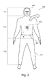
- Fig. 3 shows another exemplary embodiment of the suit system 100.
- the suit 101 in turn has the head portion 111, the upper body portion 112 and the leg portion 113 on.
- Fig. 3 is the face of the person 200 indicated to clarify that in Fig. 3 the front of the suit 101 is shown.
- the penetration of the coupling element 103 is shown.
- a closure 301 of the suit 100 which may be formed for example as a zipper.
- the closure 301 extends under the shoulders of the person 200 along the front of the suit 101.
- the closure 301 at least partially separates the suit 101 into a suit shell I and a suit base II.
- the suit 101 is not separated by the fastener 301. If the closure 301 is opened, the person 200 can pull the suit 101 over the head and put it on the back side of the person 200 (see arrow in FIG Fig. 3 ).
- the person 200 can turn the suit 101 extremely ergonomically and quickly take off.
- the person 200 can fold the suit shell I backwards and let hang down, the person 200 continues to wear the suit base II.
- the closure 300 may extend completely around the upper body region 112 so that the upper garment part I can be removed entirely from the lower garment part II.
- Fig. 4 shows the suit system 100, wherein the suit system 100 is coupled to the securing element 400.
- a penetration region 401 is also shown, in which the coupling element 103 penetrates the suit 101.
- the coupling region 401 is located in the upper body region 112 on the front side of the suit 101.
- the suit 101 in the penetration region 401 may include an additional suit material or cover (such as a flexible suit section 501 which is shown in FIG Fig. 5 shown in more detail), which Stoffumhüllung is attached to the outside of the suit 101 sealing.
- an additional suit material or cover such as a flexible suit section 501 which is shown in FIG Fig. 5 shown in more detail
- more space is created in the space around the inside of the suit 101, for example, the coupling element 103 and the coupling element of the securing band 102 and / or the seat belt 201 accommodate.
- closure 301 which under the armpits transversely from one side of the body to an opposite side of the body along the front of the suit 101 runs and separates the suit in the suit shell I and the suit base II.
- Fig. 4 the person 200 shown in a hanging position, wherein the person 200 is freely suspended in the air on the securing element 400, which is shown as a rescue rope coupled.
- the person 200 can, for example, upright her torso in the hanging position, so that in this suspended position too, freedom of movement of the arms and thus ergonomic working of the person 200 is possible.
- this hanging position as in Fig. 4 as shown the person 200 in an upright position can continue to use their hands in coordination. Further, the field of view of the person 200 is due to the illustrated hanging position in Fig. 4 continue to be directed to the hands, so that a controlled work is still possible.
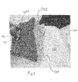
- Fig. 5 shows the suit system 100, in which a tensile force is transmitted to the coupling element 103.
- the suit 101 in Fig. 5 has the penetration area 401, through which the coupling element 103 penetrates the suit 101.
- the suit 101 has a flexible suit section 501.
- the flexible suit portion 501 can be pulled out when a tensile force is transmitted to the coupling element 103 and the coupling element 103 thus aligns with the direction of tensile force of the tensile force.
- tensions in the suit 101 are avoided because the flexible suit portion 501 expands or unfolds accordingly and compensates for the new position of the coupler 103 in the event of a tensile force transmission.
- the flexible suit section 501 has a surface on which the penetration of the coupling element 103 is formed.
- a material-bonding connection 503 (for example an adhesive connection) is used at the penetration of the coupling element 103 in order to ensure the fluid-tight passage of the coupling element 103.
- the surface of the penetration area 401 may be at a tensile force transmission spaced from a tightening surface 505 surrounding the penetration area 401 and the flexible tightening portion 501, respectively.
- the suit 101 has an edge portion 504 which surrounds and partially overlaps the flexible suit portion 501.
- the skirt portion 504 reinforces the suit 101 in the area around the flexible suit portion 501.
- the skirt portion 504 prevents unwanted unfolding of the bellows portion 502 of the flexible suit portion 501 when no tensile force is transmitted.
- the edge portion 504 thus creates a certain resistance, which prevents unfolding of the bellows-shaped portion 502 of the flexible tightening portion 501. Only when a greater tensile force is exceeded, the edge portion 504 yields, so that the bellows-shaped portion 502 of the flexible tightening portion 501 can deploy.
- the flexible suit portion 501 is formed foldable bellows or foldable. Upon transmission of the tensile force, the bellows-shaped portion 502 of the flexible tightening portion 501 unfolds so that the surface of the penetrating portion 501 is spaced from the tightening surface 505.
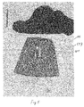
- FIG. 12 shows the exemplary embodiment of the flexible suit portion 501 according to FIG Fig. 5 , where in Fig. 6 no tensile force is transmitted via the coupling element 103.
- the flexible suit portion 501 is thus shown in a retracted state, so that the surface of the penetration area 401 is approximately on a plane like the
- Suit surface 505, which surrounds the flexible suit portion 501 is located.
- the edge portion 504 at least partially overlaps the surface of the flexible tightening portion 501.
Landscapes
- Health & Medical Sciences (AREA)
- General Health & Medical Sciences (AREA)
- Physical Education & Sports Medicine (AREA)
- Engineering & Computer Science (AREA)
- Textile Engineering (AREA)
- Business, Economics & Management (AREA)
- Emergency Management (AREA)
- Professional, Industrial, Or Sporting Protective Garments (AREA)
Applications Claiming Priority (1)
| Application Number | Priority Date | Filing Date | Title |
|---|---|---|---|
| DE102011084657 | 2011-10-17 |
Publications (3)
| Publication Number | Publication Date |
|---|---|
| EP2589414A2 true EP2589414A2 (fr) | 2013-05-08 |
| EP2589414A3 EP2589414A3 (fr) | 2013-12-25 |
| EP2589414B1 EP2589414B1 (fr) | 2016-03-23 |
Family
ID=47115399
Family Applications (1)
| Application Number | Title | Priority Date | Filing Date |
|---|---|---|---|
| EP12188845.7A Not-in-force EP2589414B1 (fr) | 2011-10-17 | 2012-10-17 | Combinaison de survie |
Country Status (2)
| Country | Link |
|---|---|
| EP (1) | EP2589414B1 (fr) |
| DK (1) | DK2589414T3 (fr) |
Cited By (2)
| Publication number | Priority date | Publication date | Assignee | Title |
|---|---|---|---|---|
| WO2014121784A1 (fr) * | 2013-02-04 | 2014-08-14 | Lhd Group Gmbh | Veste de protection comportant un système de sangle de sécurité |
| FR3043311A1 (fr) * | 2015-11-06 | 2017-05-12 | Honeywell Int Inc |
Family Cites Families (3)
| Publication number | Priority date | Publication date | Assignee | Title |
|---|---|---|---|---|
| US2979153A (en) * | 1958-01-24 | 1961-04-11 | Standard Safety Equipment Co | Safety suit |
| US4253198A (en) * | 1979-05-29 | 1981-03-03 | Estabrook James R | Rescue suit |
| US5220976A (en) * | 1991-04-08 | 1993-06-22 | Gunter Larry W | Safety harness |
-
2012
- 2012-10-17 DK DK12188845.7T patent/DK2589414T3/en active
- 2012-10-17 EP EP12188845.7A patent/EP2589414B1/fr not_active Not-in-force
Non-Patent Citations (1)
| Title |
|---|
| None |
Cited By (2)
| Publication number | Priority date | Publication date | Assignee | Title |
|---|---|---|---|---|
| WO2014121784A1 (fr) * | 2013-02-04 | 2014-08-14 | Lhd Group Gmbh | Veste de protection comportant un système de sangle de sécurité |
| FR3043311A1 (fr) * | 2015-11-06 | 2017-05-12 | Honeywell Int Inc |
Also Published As
| Publication number | Publication date |
|---|---|
| EP2589414A3 (fr) | 2013-12-25 |
| EP2589414B1 (fr) | 2016-03-23 |
| DK2589414T3 (en) | 2016-07-04 |
Similar Documents
| Publication | Publication Date | Title |
|---|---|---|
| DE212016000216U1 (de) | Schützende integrierte Haube für Bekleidung | |
| EP2589414B1 (fr) | Combinaison de survie | |
| US20170368388A1 (en) | Firefighter multifunction ladder and escape belt | |
| DE202005020354U1 (de) | Schutzgurt und Schutzbekleidungsweste | |
| DE8534081U1 (de) | Rettungsweste | |
| EP3704979B1 (fr) | Vêtement de protection | |
| EP2904917B1 (fr) | Vêtement protecteur doté d'un système de surveillance intégré | |
| DE10037868B4 (de) | Verfahren und Gerät zur Rettung von verunglückten Personen | |
| EP4249081B1 (fr) | Dispositif de sauvetage d'une personne d'une eolienne et eolienne | |
| EP2991518B1 (fr) | Vêtement de sécurité | |
| EP1222004B1 (fr) | Vetement de securite pour le travail et les sauvetages | |
| EP2420291A1 (fr) | Ceinture ventrale et système de harnais | |
| DE202012001063U1 (de) | Schutzbekleidung | |
| DE10343072A1 (de) | Auffanggurt, insbesondere für Feuerwehrleute | |
| DE102019001527A1 (de) | Integriertes Rettungssystem für Feuerwehrüberjacke | |
| DE2727443A1 (de) | Sicherheitsvorrichtung fuer personen in fahrzeugen | |
| EP1537795B1 (fr) | Vêtement avec harnais incorporé | |
| DE202017101921U1 (de) | Vorrichtung zum Transport einer verletzten, insbesondere nicht gehfähigen Person | |
| DE19640626A1 (de) | Schutzbekleidung mit Sicherheitsgurten | |
| DE20216719U1 (de) | An den Körper eines Benutzers anlegbare Absturzsicherung | |
| DE202016105893U1 (de) | Schutzjacke mit Rettungsgurt | |
| DE202023103052U1 (de) | Tragegurt-System | |
| DE680271C (de) | Freigabevorrichtung fuer die Belastungsgewichte an Taucheranzuegen | |
| DE20301867U1 (de) | Paddeljacke für Kanusportler | |
| DE202019101250U1 (de) | Vorrichtung für den Körperschutz mit integrierter Personentransportvorrichtung |
Legal Events
| Date | Code | Title | Description |
|---|---|---|---|
| PUAI | Public reference made under article 153(3) epc to a published international application that has entered the european phase |
Free format text: ORIGINAL CODE: 0009012 |
|
| AK | Designated contracting states |
Kind code of ref document: A2 Designated state(s): AL AT BE BG CH CY CZ DE DK EE ES FI FR GB GR HR HU IE IS IT LI LT LU LV MC MK MT NL NO PL PT RO RS SE SI SK SM TR |
|
| AX | Request for extension of the european patent |
Extension state: BA ME |
|
| PUAL | Search report despatched |
Free format text: ORIGINAL CODE: 0009013 |
|
| AK | Designated contracting states |
Kind code of ref document: A3 Designated state(s): AL AT BE BG CH CY CZ DE DK EE ES FI FR GB GR HR HU IE IS IT LI LT LU LV MC MK MT NL NO PL PT RO RS SE SI SK SM TR |
|
| AX | Request for extension of the european patent |
Extension state: BA ME |
|
| RIC1 | Information provided on ipc code assigned before grant |
Ipc: A62B 35/00 20060101AFI20131118BHEP Ipc: A41D 13/00 20060101ALI20131118BHEP |
|
| 17P | Request for examination filed |
Effective date: 20140226 |
|
| RBV | Designated contracting states (corrected) |
Designated state(s): AL AT BE BG CH CY CZ DE DK EE ES FI FR GB GR HR HU IE IS IT LI LT LU LV MC MK MT NL NO PL PT RO RS SE SI SK SM TR |
|
| GRAP | Despatch of communication of intention to grant a patent |
Free format text: ORIGINAL CODE: EPIDOSNIGR1 |
|
| INTG | Intention to grant announced |
Effective date: 20150518 |
|
| GRAP | Despatch of communication of intention to grant a patent |
Free format text: ORIGINAL CODE: EPIDOSNIGR1 |
|
| INTG | Intention to grant announced |
Effective date: 20150916 |
|
| GRAS | Grant fee paid |
Free format text: ORIGINAL CODE: EPIDOSNIGR3 |
|
| GRAA | (expected) grant |
Free format text: ORIGINAL CODE: 0009210 |
|
| AK | Designated contracting states |
Kind code of ref document: B1 Designated state(s): AL AT BE BG CH CY CZ DE DK EE ES FI FR GB GR HR HU IE IS IT LI LT LU LV MC MK MT NL NO PL PT RO RS SE SI SK SM TR |
|
| REG | Reference to a national code |
Ref country code: GB Ref legal event code: FG4D Free format text: NOT ENGLISH |
|
| REG | Reference to a national code |
Ref country code: CH Ref legal event code: EP |
|
| REG | Reference to a national code |
Ref country code: AT Ref legal event code: REF Ref document number: 782545 Country of ref document: AT Kind code of ref document: T Effective date: 20160415 |
|
| REG | Reference to a national code |
Ref country code: IE Ref legal event code: FG4D Free format text: LANGUAGE OF EP DOCUMENT: GERMAN |
|
| REG | Reference to a national code |
Ref country code: DE Ref legal event code: R096 Ref document number: 502012006377 Country of ref document: DE |
|
| REG | Reference to a national code |
Ref country code: DK Ref legal event code: T3 Effective date: 20160628 |
|
| REG | Reference to a national code |
Ref country code: LT Ref legal event code: MG4D |
|
| REG | Reference to a national code |
Ref country code: NL Ref legal event code: MP Effective date: 20160323 |
|
| PG25 | Lapsed in a contracting state [announced via postgrant information from national office to epo] |
Ref country code: HR Free format text: LAPSE BECAUSE OF FAILURE TO SUBMIT A TRANSLATION OF THE DESCRIPTION OR TO PAY THE FEE WITHIN THE PRESCRIBED TIME-LIMIT Effective date: 20160323 Ref country code: GR Free format text: LAPSE BECAUSE OF FAILURE TO SUBMIT A TRANSLATION OF THE DESCRIPTION OR TO PAY THE FEE WITHIN THE PRESCRIBED TIME-LIMIT Effective date: 20160624 Ref country code: FI Free format text: LAPSE BECAUSE OF FAILURE TO SUBMIT A TRANSLATION OF THE DESCRIPTION OR TO PAY THE FEE WITHIN THE PRESCRIBED TIME-LIMIT Effective date: 20160323 |
|
| REG | Reference to a national code |
Ref country code: NO Ref legal event code: T2 Effective date: 20160323 |
|
| PG25 | Lapsed in a contracting state [announced via postgrant information from national office to epo] |
Ref country code: LT Free format text: LAPSE BECAUSE OF FAILURE TO SUBMIT A TRANSLATION OF THE DESCRIPTION OR TO PAY THE FEE WITHIN THE PRESCRIBED TIME-LIMIT Effective date: 20160323 Ref country code: RS Free format text: LAPSE BECAUSE OF FAILURE TO SUBMIT A TRANSLATION OF THE DESCRIPTION OR TO PAY THE FEE WITHIN THE PRESCRIBED TIME-LIMIT Effective date: 20160323 Ref country code: SE Free format text: LAPSE BECAUSE OF FAILURE TO SUBMIT A TRANSLATION OF THE DESCRIPTION OR TO PAY THE FEE WITHIN THE PRESCRIBED TIME-LIMIT Effective date: 20160323 Ref country code: LV Free format text: LAPSE BECAUSE OF FAILURE TO SUBMIT A TRANSLATION OF THE DESCRIPTION OR TO PAY THE FEE WITHIN THE PRESCRIBED TIME-LIMIT Effective date: 20160323 Ref country code: NL Free format text: LAPSE BECAUSE OF FAILURE TO SUBMIT A TRANSLATION OF THE DESCRIPTION OR TO PAY THE FEE WITHIN THE PRESCRIBED TIME-LIMIT Effective date: 20160323 |
|
| PG25 | Lapsed in a contracting state [announced via postgrant information from national office to epo] |
Ref country code: EE Free format text: LAPSE BECAUSE OF FAILURE TO SUBMIT A TRANSLATION OF THE DESCRIPTION OR TO PAY THE FEE WITHIN THE PRESCRIBED TIME-LIMIT Effective date: 20160323 Ref country code: PL Free format text: LAPSE BECAUSE OF FAILURE TO SUBMIT A TRANSLATION OF THE DESCRIPTION OR TO PAY THE FEE WITHIN THE PRESCRIBED TIME-LIMIT Effective date: 20160323 Ref country code: IS Free format text: LAPSE BECAUSE OF FAILURE TO SUBMIT A TRANSLATION OF THE DESCRIPTION OR TO PAY THE FEE WITHIN THE PRESCRIBED TIME-LIMIT Effective date: 20160723 |
|
| PG25 | Lapsed in a contracting state [announced via postgrant information from national office to epo] |
Ref country code: SM Free format text: LAPSE BECAUSE OF FAILURE TO SUBMIT A TRANSLATION OF THE DESCRIPTION OR TO PAY THE FEE WITHIN THE PRESCRIBED TIME-LIMIT Effective date: 20160323 Ref country code: ES Free format text: LAPSE BECAUSE OF FAILURE TO SUBMIT A TRANSLATION OF THE DESCRIPTION OR TO PAY THE FEE WITHIN THE PRESCRIBED TIME-LIMIT Effective date: 20160323 Ref country code: SK Free format text: LAPSE BECAUSE OF FAILURE TO SUBMIT A TRANSLATION OF THE DESCRIPTION OR TO PAY THE FEE WITHIN THE PRESCRIBED TIME-LIMIT Effective date: 20160323 Ref country code: RO Free format text: LAPSE BECAUSE OF FAILURE TO SUBMIT A TRANSLATION OF THE DESCRIPTION OR TO PAY THE FEE WITHIN THE PRESCRIBED TIME-LIMIT Effective date: 20160323 Ref country code: PT Free format text: LAPSE BECAUSE OF FAILURE TO SUBMIT A TRANSLATION OF THE DESCRIPTION OR TO PAY THE FEE WITHIN THE PRESCRIBED TIME-LIMIT Effective date: 20160725 Ref country code: CZ Free format text: LAPSE BECAUSE OF FAILURE TO SUBMIT A TRANSLATION OF THE DESCRIPTION OR TO PAY THE FEE WITHIN THE PRESCRIBED TIME-LIMIT Effective date: 20160323 |
|
| PG25 | Lapsed in a contracting state [announced via postgrant information from national office to epo] |
Ref country code: IT Free format text: LAPSE BECAUSE OF FAILURE TO SUBMIT A TRANSLATION OF THE DESCRIPTION OR TO PAY THE FEE WITHIN THE PRESCRIBED TIME-LIMIT Effective date: 20160323 |
|
| REG | Reference to a national code |
Ref country code: DE Ref legal event code: R097 Ref document number: 502012006377 Country of ref document: DE |
|
| PLBE | No opposition filed within time limit |
Free format text: ORIGINAL CODE: 0009261 |
|
| STAA | Information on the status of an ep patent application or granted ep patent |
Free format text: STATUS: NO OPPOSITION FILED WITHIN TIME LIMIT |
|
| PG25 | Lapsed in a contracting state [announced via postgrant information from national office to epo] |
Ref country code: BE Free format text: LAPSE BECAUSE OF NON-PAYMENT OF DUE FEES Effective date: 20161031 Ref country code: BG Free format text: LAPSE BECAUSE OF FAILURE TO SUBMIT A TRANSLATION OF THE DESCRIPTION OR TO PAY THE FEE WITHIN THE PRESCRIBED TIME-LIMIT Effective date: 20160623 |
|
| 26N | No opposition filed |
Effective date: 20170102 |
|
| PG25 | Lapsed in a contracting state [announced via postgrant information from national office to epo] |
Ref country code: SI Free format text: LAPSE BECAUSE OF FAILURE TO SUBMIT A TRANSLATION OF THE DESCRIPTION OR TO PAY THE FEE WITHIN THE PRESCRIBED TIME-LIMIT Effective date: 20160323 |
|
| REG | Reference to a national code |
Ref country code: CH Ref legal event code: PL |
|
| REG | Reference to a national code |
Ref country code: IE Ref legal event code: MM4A |
|
| REG | Reference to a national code |
Ref country code: FR Ref legal event code: ST Effective date: 20170630 |
|
| PG25 | Lapsed in a contracting state [announced via postgrant information from national office to epo] |
Ref country code: FR Free format text: LAPSE BECAUSE OF NON-PAYMENT OF DUE FEES Effective date: 20161102 Ref country code: LI Free format text: LAPSE BECAUSE OF NON-PAYMENT OF DUE FEES Effective date: 20161031 Ref country code: CH Free format text: LAPSE BECAUSE OF NON-PAYMENT OF DUE FEES Effective date: 20161031 |
|
| PG25 | Lapsed in a contracting state [announced via postgrant information from national office to epo] |
Ref country code: LU Free format text: LAPSE BECAUSE OF NON-PAYMENT OF DUE FEES Effective date: 20161017 |
|
| PG25 | Lapsed in a contracting state [announced via postgrant information from national office to epo] |
Ref country code: IE Free format text: LAPSE BECAUSE OF NON-PAYMENT OF DUE FEES Effective date: 20161017 |
|
| REG | Reference to a national code |
Ref country code: BE Ref legal event code: MM Effective date: 20161031 |
|
| PG25 | Lapsed in a contracting state [announced via postgrant information from national office to epo] |
Ref country code: CY Free format text: LAPSE BECAUSE OF FAILURE TO SUBMIT A TRANSLATION OF THE DESCRIPTION OR TO PAY THE FEE WITHIN THE PRESCRIBED TIME-LIMIT Effective date: 20160323 Ref country code: HU Free format text: LAPSE BECAUSE OF FAILURE TO SUBMIT A TRANSLATION OF THE DESCRIPTION OR TO PAY THE FEE WITHIN THE PRESCRIBED TIME-LIMIT; INVALID AB INITIO Effective date: 20121017 |
|
| PG25 | Lapsed in a contracting state [announced via postgrant information from national office to epo] |
Ref country code: TR Free format text: LAPSE BECAUSE OF FAILURE TO SUBMIT A TRANSLATION OF THE DESCRIPTION OR TO PAY THE FEE WITHIN THE PRESCRIBED TIME-LIMIT Effective date: 20160323 Ref country code: MT Free format text: LAPSE BECAUSE OF FAILURE TO SUBMIT A TRANSLATION OF THE DESCRIPTION OR TO PAY THE FEE WITHIN THE PRESCRIBED TIME-LIMIT Effective date: 20160323 Ref country code: MC Free format text: LAPSE BECAUSE OF FAILURE TO SUBMIT A TRANSLATION OF THE DESCRIPTION OR TO PAY THE FEE WITHIN THE PRESCRIBED TIME-LIMIT Effective date: 20160323 Ref country code: MK Free format text: LAPSE BECAUSE OF FAILURE TO SUBMIT A TRANSLATION OF THE DESCRIPTION OR TO PAY THE FEE WITHIN THE PRESCRIBED TIME-LIMIT Effective date: 20160323 |
|
| PG25 | Lapsed in a contracting state [announced via postgrant information from national office to epo] |
Ref country code: AL Free format text: LAPSE BECAUSE OF FAILURE TO SUBMIT A TRANSLATION OF THE DESCRIPTION OR TO PAY THE FEE WITHIN THE PRESCRIBED TIME-LIMIT Effective date: 20160323 |
|
| REG | Reference to a national code |
Ref country code: AT Ref legal event code: MM01 Ref document number: 782545 Country of ref document: AT Kind code of ref document: T Effective date: 20171017 |
|
| PG25 | Lapsed in a contracting state [announced via postgrant information from national office to epo] |
Ref country code: AT Free format text: LAPSE BECAUSE OF NON-PAYMENT OF DUE FEES Effective date: 20171017 |
|
| PGFP | Annual fee paid to national office [announced via postgrant information from national office to epo] |
Ref country code: DK Payment date: 20201027 Year of fee payment: 9 Ref country code: GB Payment date: 20201027 Year of fee payment: 9 Ref country code: DE Payment date: 20201030 Year of fee payment: 9 Ref country code: NO Payment date: 20201028 Year of fee payment: 9 |
|
| REG | Reference to a national code |
Ref country code: DE Ref legal event code: R119 Ref document number: 502012006377 Country of ref document: DE |
|
| REG | Reference to a national code |
Ref country code: NO Ref legal event code: MMEP Ref country code: DK Ref legal event code: EBP Effective date: 20211031 |
|
| GBPC | Gb: european patent ceased through non-payment of renewal fee |
Effective date: 20211017 |
|
| PG25 | Lapsed in a contracting state [announced via postgrant information from national office to epo] |
Ref country code: NO Free format text: LAPSE BECAUSE OF NON-PAYMENT OF DUE FEES Effective date: 20211031 Ref country code: GB Free format text: LAPSE BECAUSE OF NON-PAYMENT OF DUE FEES Effective date: 20211017 Ref country code: DE Free format text: LAPSE BECAUSE OF NON-PAYMENT OF DUE FEES Effective date: 20220503 |
|
| PG25 | Lapsed in a contracting state [announced via postgrant information from national office to epo] |
Ref country code: DK Free format text: LAPSE BECAUSE OF NON-PAYMENT OF DUE FEES Effective date: 20211031 |
|
| P01 | Opt-out of the competence of the unified patent court (upc) registered |
Effective date: 20230524 |