EP2589452B3 - Fräswerkzeug, Vorrichtung mit einem solchen Fräswerkzeug und Verfahren für die Herstellung von Dentalkörpern - Google Patents
Fräswerkzeug, Vorrichtung mit einem solchen Fräswerkzeug und Verfahren für die Herstellung von Dentalkörpern Download PDFInfo
- Publication number
- EP2589452B3 EP2589452B3 EP12190885.9A EP12190885A EP2589452B3 EP 2589452 B3 EP2589452 B3 EP 2589452B3 EP 12190885 A EP12190885 A EP 12190885A EP 2589452 B3 EP2589452 B3 EP 2589452B3
- Authority
- EP
- European Patent Office
- Prior art keywords
- milling tool
- tool according
- cutter
- elevations
- milling
- Prior art date
- Legal status (The legal status is an assumption and is not a legal conclusion. Google has not performed a legal analysis and makes no representation as to the accuracy of the status listed.)
- Active
Links
Images

Classifications
-
- B—PERFORMING OPERATIONS; TRANSPORTING
- B23—MACHINE TOOLS; METAL-WORKING NOT OTHERWISE PROVIDED FOR
- B23C—MILLING
- B23C5/00—Milling-cutters
- B23C5/02—Milling-cutters characterised by the shape of the cutter
- B23C5/10—Shank-type cutters, i.e. with an integral shaft
- B23C5/1009—Ball nose end mills
-
- A—HUMAN NECESSITIES
- A61—MEDICAL OR VETERINARY SCIENCE; HYGIENE
- A61C—DENTISTRY; APPARATUS OR METHODS FOR ORAL OR DENTAL HYGIENE
- A61C3/00—Dental tools or instruments
- A61C3/02—Tooth drilling or cutting instruments; Instruments acting like a sandblast machine
-
- B—PERFORMING OPERATIONS; TRANSPORTING
- B23—MACHINE TOOLS; METAL-WORKING NOT OTHERWISE PROVIDED FOR
- B23C—MILLING
- B23C2210/00—Details of milling cutters
- B23C2210/20—Number of cutting edges
- B23C2210/201—Number of cutting edges one
-
- B—PERFORMING OPERATIONS; TRANSPORTING
- B23—MACHINE TOOLS; METAL-WORKING NOT OTHERWISE PROVIDED FOR
- B23C—MILLING
- B23C2210/00—Details of milling cutters
- B23C2210/32—Details of teeth
- B23C2210/321—Lands, i.e. the area on the rake face in the immediate vicinity of the cutting edge
-
- B—PERFORMING OPERATIONS; TRANSPORTING
- B23—MACHINE TOOLS; METAL-WORKING NOT OTHERWISE PROVIDED FOR
- B23C—MILLING
- B23C2210/00—Details of milling cutters
- B23C2210/44—Margins, i.e. the part of the peripheral suface immediately adacent the cutting edge
-
- B—PERFORMING OPERATIONS; TRANSPORTING
- B23—MACHINE TOOLS; METAL-WORKING NOT OTHERWISE PROVIDED FOR
- B23C—MILLING
- B23C2226/00—Materials of tools or workpieces not comprising a metal
- B23C2226/61—Plastics not otherwise provided for, e.g. nylon
Definitions
- the invention relates to a milling tool, a device with such a milling tool for the production of dental bodies and a method for producing dental bodies using such a milling tool.
- Milling tools are known in great variety of forms and for different purposes.
- Heicko fferen GmbH for example, is familiar with a single-edged water slot cutter with a drill point and teeth ground into the lateral surface with the same twist as the spiral cutting edge.
- the company Spannabriolde Deutschenberichte GmbH offers u. a. a Ein leopardfräser with such in the lateral surface ground teeth and a spur radius.
- a similar burr with barb radius from vhf camfacture AG is indicated as suitable for roughing and for softer materials.
- thermoplastics such as those with regard to the materials for the dental body.
- thermoplastic PMMA or in particular PEEK thermoplastic PMMA or in particular PEEK.
- the loss heat generated during processing, in particular due to friction can not be dissipated sufficiently quickly and damage, in particular deformation of the workpiece, can occur.
- the dental laboratories are therefore faced with the dilemma of either making high investments in processing stations with active fluid cooling or the production of dental bodies made of such plastics or not be able to offer economically because of the risk of high scrap.
- One from the DE 20105015 U1 known milling cutter for the dental sector has a plurality of circumferentially offset from each other cutting the same direction of twist and at these cutting edges of different sizes scores first and second order as a so-called cross-toothing.
- the tool insert for a hand drill known.
- the tool insert has an annular groove, which continues in a spiral shape. On opposite sides of a helical recess is provided.
- a woodworking tool in the form of a router which shows a peripheral edge as the main cutting edge and a front cutting edge as a minor cutting edge.
- the present invention is therefore an object of the invention to provide a milling tool and a device with such a milling tool for the production of dental bodies and a method for producing dental bodies using such a tool, which cost the processing of such polymer plastics, such as chemoplastics and in particular thermoplastic materials without liquid cooling allow.
- the coiled main train can be formed with advantageously large diameter and thereby cause a rapid removal of chips from the cutting point in particular from the first cutting edge forming a radius cutting edge at the tip of the milling tool.
- the area fraction of the main draw within a cross-sectional area perpendicular to the axis of rotation of the rotational volume of the milling tool determined by the cutting arrangement is advantageously at least 30%, in particular at least 40%.
- milling tool or a device containing such a milling tool advantageously allows a process for the production of dental bodies, in particular dental prosthesis bodies in dental laboratories with there usually existing equipment.
- the milling can be done without supply of cooling fluid to the milling position of the milling tool on the plastic workpiece.
- the area fraction of the material cross-section of the base body at the cross-sectional area of the rotation volume is advantageously at least 50%.
- the size of a possibly occurring friction surface on contact of the relief grinding structure with the material of the workpiece is limited to the elevations and thus the heat generation can be kept low by the depressions in the relief grinding structure.
- the area fraction of the elevations, which possibly come into frictional contact with the thermoplastic material of the workpiece, on the total area of the lateral surface is advantageously less than 20%, in particular less than 10%, of the lateral surface.
- the possible contact surfaces in the elevation are approximately linear.
- a plurality of elevations and depressions are arranged successively at all longitudinal positions of the longitudinal section of the base body in the circumferential direction between the leading edge in the working direction and the trailing edge of the lateral opening of the main train.
- the enveloping lines of the circumferential lines of the lateral surface in cross sections perpendicular to the axis of rotation extend from a maximum radius at the cutting edge of the lateral opening of the main train substantially helically with continuously decreasing radius to the rear edge with a minimum radius.
- the radius difference between the cutting edge and the rear edge is advantageously at least 5%, in particular at least 10% of the maximum radius, which advantageously allows a large chip thickness and thus a low heat development per removed volume unit.
- a twist angle of the second cutting edge is advantageously not more than 45 °, in particular not more than 35 °, which favors a high cutting performance in thermoplastic materials.
- the radial depression of the depressions against the circumferentially adjacent thereto elevations is advantageously at least 1%, in particular at least 1.5% of the radius of the rotary volume.
- the radial depression is advantageously not greater than 5%, in particular 3% of the radius of the rotary volume, whereby a reduction of the material cross section of the base body can be advantageously kept low by the wells.
- the relief-cut structure is formed in a preferred embodiment by a plurality of trained as coiled depressions in the lateral surface trains, hereinafter referred to differentiate from the main train as a side cables.
- the side cables advantageously have the same helical pitch as the main train and the coiled second cutting edge.
- the side cables are advantageously produced by a rotating grinding tool, in a preferred procedure by the same grinding tool, which is used to produce the main train, inexpensive.
- the tip of the milling tool with the radius-cutting, which causes an axially curved sub-volume of the rotational volume is formed by ground on the end face of the milling tool flanks for an axial insertion of the milling tool into the workpiece.
- the radius cutting edge as the first cutting edge of the cutting arrangement advantageously extends by a small amount past the rotation axis of the milling tool and beyond. This favors a correct representation of a cutting radius on the workpiece.
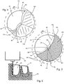
- Fig. 1 shows a lateral view as viewed perpendicular to the axis of rotation RA a milling tool according to the invention.
- the milling tool is designed as an end mill with a shank SC for clamping in a processing machine.
- On the shaft SC of the axially opposite tip of the milling tool a rounded radius cutting edge SR is formed, which allows the use of the milling tool as a radius cutter.
- the radius cutting edge SR is also referred to below as the first cutting edge.
- the axial section in which the radius cutting edge SR is effective is denoted by RB.
- a second cutting edge SW running around the rotational axis RA is formed on the tool.
- the second cutting edge SW preferably runs with a constant radius with respect to the axis of rotation RA.
- the enveloping rotational volume taken on rotation of the milling tool about the axis of rotation RA from the one-sectional cutting arrangement with the first cutting edge SR and the second cutting edge SW is shown in FIG Fig. 1 shown with a broken line.
- the rotation volume HV has in the longitudinal section WS the constant diameter DF.
- the formation of a constant diameter is of particular advantage, in particular with regard to the production of the tool, but is not mandatory.
- the diameter DF is, in particular at the transition to the tip region RB, not greater than 3 mm, in particular not greater than 2 mm.
- the rotation volume takes the form of a convexly curved body of revolution away from the milling tool.
- the axial regions RB and WB are referred to as the main body.
- the milling tool is preferably made of one piece material homogeneous.
- a main HZ in the form of a coiled recess with a coincident with the axis of rotation RA coil axis.
- the main pull HZ is formed in an advantageous embodiment over the entire work area formed by the longitudinal area WB and radius area RB of the main body of the milling tool with a constant cross section.
- the lateral, radially outwardly facing opening of the main pull HZ is limited by the coiled second cutting edge SW as an opening edge and a circumferentially opposite second edge RK, which is also referred to as the rear edge.
- Fig. 3 is enlarged a cross section through a milling tool of the type Fig. 1 shown with a sectional plane perpendicular to the axis of rotation RA in the region of the longitudinal section WB.
- the second cutting edge SW forms a pointing in the direction of rotation DR cutting edge, which with their distance RS the envelope of the rotational volume HV in the sectional plane of the Fig. 3 certainly.
- the rear edge KR runs coiled in a relation to the second cutting SW SW smaller radius RR from the axis of rotation DA.
- the following after the free surface FW peripheral surface of the milling tool, which is referred to as a lateral surface or as a rear surface extends approximately spirally with decreasing radius up to the rear edge KR.
- the recess forming the main pull HZ in the cross-section of the milling tool advantageously extends as in FIG Fig. 3 outlines approximately to the rotation axis RA and in a preferred embodiment by a small amount, which is advantageously not greater than 10% of the radius RS, beyond the axis of rotation.
- the body then has no core or soul.
- an undercut structure is formed, which has a plurality of circumferentially successive recesses MT and elevations ME.
- the elevations ME are preferably approximately on a spiral path from the cutting edge SW to the rear edge RK.
- the extent of the elevations ME in the circumferential direction is advantageously so small that the surface portion of the elevations ME on the lateral surface is at most 20%, in particular not more than 10%.
- the elevations ME in the lateral surface are substantially linear through the plane of the drawing Fig. 3 formed piercing.
- the depressions MT have a radial depression TN relative to the elevations ME, which is advantageously at least 1%, in particular at least 1.5% of the radius RS of the second cutting edge SW and at most 5%, in particular not more than 3% of the radius RS of the second cutting edge SW ,
- successive elevations ME are advantageously spaced by an angle WE of at least 15 °, in particular at least 20 ° from each other.
- the width of the recesses MT in the circumferential direction is advantageously less than 50 °, in particular less than 40 °, preferably less than 35 °, which is advantageous for a radial uniform support.
- the number of recesses is smaller for smaller cutting radii RS than for larger cutting radii.
- the cutting radii RS are advantageously not greater than 1.5 mm, in particular not greater than 1 mm, for the production of dental bodies.
- the elevations ME and depressions MT in the lateral surface of the milling tool facing away from the main pull HZ are in a preferred embodiment as shown in FIG Fig. 1 can be seen as coiled depressions formed against an envelope surface of the lateral surface. These depressions of the relief-grinding structure are also referred to below as side-draws NZ.
- the Maurat are preferably coiled with a coiled course of the second cutting edge SW same Wendelgang invented. Due to the approximately spirally extending envelope lines of the peripheral lines of the lateral surface, a greater helical pitch and a smaller radius than for the secondary blade near the second cutting edge SW results for the side branches near the rear edge KR. Due to the radius decreasing from the cutting edge SW to the back edge KR, the projection of the milling tool appears in the in Fig. 1 shown with a deviating from the envelope surface of the rotational volume DF conical course.
- the opening angle WE of the radially outwardly laterally outwardly facing opening of the main pull HZ is advantageously at least 110 °, in particular at least 130 °.
- the opening angle WH is not more than 180 °, in particular not more than 160 °.
- the area fraction of the main train HZ at the is advantageously at least 30%, in particular at least 40% of the circular area and advantageously at most 60%, in particular at most 50% of the circular area by the enveloping circle of the rotational volume HV specific cross-sectional area.
- a large chip thickness is given in particular by the radius difference of the rear edge KR against the second cutting edge SW.
- a high chip removal is advantageously favored by a small helix angle WD.
- Due to the incision-type design of the tool advantageously remains sufficient for the stability of the tool during milling operation material cross-sectional area MQ of the main body of the milling tool, which in Fig. 3 hatched.
- the plurality of recesses MT in the circumferential surface of the tool section in the longitudinal section WB advantageously causes a small contact surface of the tool with the thermoplastic material of the workpiece and thereby a low heat development.
- the relief grinding structure with the secondary draws NZ in the lateral surface of the longitudinal section WB of the milling tool can be produced in an advantageous embodiment by means of a grinding tool, wherein preferably in the production of the Maurat NZ same grinding tool can be used, which is also used for the production of Hauptzugs HZ.
- the control of the grinding tool for main train and side cables is advantageously easy.
- the approximately line-shaped coiled elevations of the relief grinding structure thereby automatically result as cutting lines of the curved grinding tool surfaces of the successively ground side cables.
- a freewheel FZ which in Fig. 1 is mostly obscured.
- Figure 4 is shown in an axial view of the tip of the milling tool, a preferred embodiment of the fingerschliffs FZ.
- the first edge SR which is against the plane of the drawing Fig. 4 arched, a first, the cutting edge of the first cutting edge approximately following free surface FR is assigned.
- FZ1 and FZ2 Farther away from the first cutting edge SR in the circumferential direction, there are free surfaces FZ1 and FZ2, which can be formed by flat surfaces in order to produce them in an advantageous manner.
- a further flank FZ3 is ground steeper against the direction of the axis of rotation directly on the main pull HZ than the flank faces FZ1 and FZ2. It turns out that the steeper cut of the further open space FZ3 advantageously favors the breaking off of material chips.
- the resulting from the intersection of the other free surface FZ3 with the main HZ edge in the end face is denoted by KF.
- the radius cutting edge SR as the first cutting edge of the single-cutting cutting arrangement extends from the second cutting edge SW forth in the view Fig. 4 curved towards the axis of rotation RA and spaced by a small amount radially from the axis of rotation at this past and by a small amount beyond this.
- Fig. 2 shows in longitudinal cut representation with against the plane of rotation twisted cutting plane another milling tool in Fig. 1 shown, in which example the helical pitch of the coiled structures is greater than in the example of Fig. 1 ,
- Out Fig. 2 clearly shows the course of the rotation axis RA with comprehensive Hauptzugs HZ.
- the free-edge FR is also clearly visible immediately behind the first edge SR and edge KF.
- Fig. 5 shows schematically the use of a milling tool WZ of the type described in the manufacture of dental bodies, such as dental crowns, from a thermoplastic or thermoplastic plastic workpiece WS. Due to the fine structures, in particular cavities in the dental bodies Z1, Z2 milling tools are required in relation to the diameter of great length.
- Fig. 5 shows an intermediate stage of the milling process, in which a part of the structures of the dental body Z1, Z2 are already created. The final contours are drawn with broken lines.
- a material removal by the milling tool FZ is carried out both by the radius cutting edge at the tip of the tool and by the coiled second cutting edge in the longitudinal region WB of the tool.
- the milling tool WZ is clamped in a receptacle of a drive device AE and driven in the milling operation with preferably more than 10,000 revolutions per minute.
Landscapes
- Health & Medical Sciences (AREA)
- Oral & Maxillofacial Surgery (AREA)
- Dentistry (AREA)
- Epidemiology (AREA)
- Life Sciences & Earth Sciences (AREA)
- Animal Behavior & Ethology (AREA)
- General Health & Medical Sciences (AREA)
- Public Health (AREA)
- Veterinary Medicine (AREA)
- Engineering & Computer Science (AREA)
- Mechanical Engineering (AREA)
- Dental Tools And Instruments Or Auxiliary Dental Instruments (AREA)
- Milling Processes (AREA)
Description
- Die Erfindung betrifft ein Fräswerkzeug, eine Vorrichtung mit einem solchen Fräswerkzeug für die Herstellung von Dentalkörpern sowie ein Verfahren zur Herstellung von Dentalkörpern unter Verwendung eines solchen Fräswerkzeugs.
- Fräswerkzeuge sind in großer Formvielfalt und für unterschiedliche Einsatzzwecke bekannt. Von Heicko Schrauben GmbH ist beispielsweise ein einschneidiger Wasserschlitzfräser mit Bohrspitze und in die Mantelfläche eingeschliffenen Zügen mit zur Wendelschneide gleichem Drall bekannt. Die Firma Spanabhebende Werkzeuge GmbH bietet u. a. einen Einzahnfräser mit solchen in die Mantelfläche eingeschliffenen Zügen und einem Stirnradius an. Ein ähnlicher Einzahnfräser mit Stirnradius von der vhf camfacture AG ist als zum Schruppen und für weichere Materialien geeignet angegeben.
- Für die Herstellung von Dentalkörpern wie z. B. Zahnkronen oder Brücken sind Fräser erforderlich, welche in Freiformfräsen weitgehend beliebig dreidimensional unregelmäßig gekrümmte Geometrien sehr kleiner Abmessungen ermöglichen.
- Für die Herstellung von Dentalkörpern, insbesondere Zahnprothesenkörpern werden in Dentallaboren zunehmend numerisch steuerbare Bearbeitungsstationen eingesetzt. Für die Bearbeitung typischer Werkstoffe können dabei vorteilhafterweise kostengünstige Vorrichtungen mit trockener, kühlfluidfreier Werkstückbearbeitung eingesetzt werden. Es zeigt sich aber hinsichtlich der Materialien für die Dentalkörper ein Trend zu Kunststoffen, insbesondere Thermoplasten, wie z. B. thermoplastisches PMMA oder insbesondere PEEK. Solche Kunststoffe sind zwar in Werkzeugmaschinen mit Flüssigkeitskühlung am Bearbeitungsbereich bearbeitbar, insbesondere fräsbar. Bei trockener, kühlfluidfreier Bearbeitung in den herkömmlichen Bearbeitungsstationen der Dentallabore kann die bei der Bearbeitung insbesondere durch Reibung entstehende Verlustwärme aber nicht hinreichend schnell abgeführt werden und es kann zu Beschädigungen, insbesondere Verformungen des Werkstücks kommen. Die Dentallabore stehen daher vor dem Dilemma, entweder hohe Investitionen für Bearbeitungsstationen mit aktiver Fluidkühlung zu tätigen oder die Herstellung von Dentalkörpern aus solchen Kunststoffen nicht oder wegen der Gefahr hohen Ausschusses nicht wirtschaftlich anbieten zu können.
- Ein aus der
DE 20105015 U1 bekannter Fräser für den Dentalbereich weist mehrere in Umfangsrichtung gegeneinander versetzte Schneiden gleicher Drallrichtung und an diesen Schneiden unterschiedlich große Kerben erster und zweiter Ordnung als eine sogenannte Kreuzverzahnung auf. - Aus der
US 2011/268517 A1 ist ein Werkzeugeinsatz für eine Handbohrmaschine bekannt. Der Werkzeugeinsatz weist eine ringförmige Auskehlung auf, die sich spiralförmig fortsetzt. An gegenüber liegenden Seiten ist eine helixförmige Aussparung vorgesehen. - In der
DD 289 231 A5 - In der Druckschrift
US 664 876 A wird ein Bohrer gezeigt, der über bleibende Bruchstücke leicht entfernt. Dazu ist eine helixförmige Hauptschneide vorgesehen, die in Zwischenbereichen eine Feinstrukturierung aufweist. Dabei kann es sich entweder um eine Profilierung handeln, die als Kreuzprofil ausgebildet ist oder es sind einzelne parallele Schneidkanten vorgesehen. - Von der Firma Digital Dental Solutions sind verschiedene Vollhartmetall-Radiusfräser bekannt, welche für die Bearbeitung von Zirkon oder PMMA, Wachs, Gips ausgebildet sein können.
- Die vorstehend erwähnten Fräswerkzeuge für den Dentalbereich erweisen sich in der Praxis für die Herstellung von Dentalkörpern insbesondere aus thermoplastischen Materialien nicht als befriedigend. Insbesondere treten immer wieder lokale Überhitzungen des thermoplastischen Materials auf, wodurch häufig das bis dahin bearbeitete Werkstück verworfen werden muss.
- Der vorliegenden Erfindung liegt daher die Aufgabe zugrunde, ein Fräswerkzeug und eine Vorrichtung mit einem solchen Fräswerkzeug für die Herstellung von Dentalkörpern sowie ein Verfahren zur Herstellung von Dentalkörpern unter Verwendung eines solchen Werkzeugs anzugeben, welche kostengünstig die Bearbeitung solcher Polymer-Kunststoffe, beispielsweise chemoplastischer Kunststoffe und insbesondere thermoplastischer Kunststoffe ohne Flüssigkeitskühlung ermöglichen.
- Erfindungsgemäße Lösungen sind in den unabhängigen Ansprüchen beschrieben. Die abhängigen Ansprüche enthalten vorteilhafte Ausgestaltungen und Weiterbildungen der Erfindung.
- Durch die einschnittige Schneidenanordnung kann der gewendelte Hauptzug mit vorteilhaft großem Durchmesser ausgebildet sein und dadurch eine schnelle Abfuhr von Spänen von der Schneidstelle insbesondere auch von der eine Radiusschneide bildenden ersten Schneide an der Spitze des Fräswerkzeugs bewirken. Der Flächenanteil des Hauptzugs innerhalb einer senkrecht zur Rotationsachse liegenden Querschnittsfläche des durch die Schneidenanordnung bestimmten Rotationsvolumens des Fräswerkzeugs beträgt vorteilhafterweise wenigstens 30 %, insbesondere wenigstens 40 %.
- Die Verwendung eines solchen Fräswerkzeugs bzw. einer ein solches Fräswerkzeug enthaltenden Vorrichtung ermöglicht vorteilhafterweise ein Verfahren zur Herstellung von Dentalkörpern, insbesondere Zahnprothesenkörpern in Dentallabors mit dort üblicherweise vorhandener Ausrüstung. Insbesondere kann die Fräsbearbeitung ohne Zufuhr von Kühlfluid an die Fräsposition des Fräswerkzeugs an dem Kunststoff-Werkstück erfolgen.
- Durch die an der Mantelfläche des Längsabschnitts des Grundkörpers ausgebildete Hinterschliffstruktur mit den mehreren Vertiefungen und Erhebungen zum einen kann trotz des großen Hauptzugs ein ausreichend großer Materialquerschnitt des Grundkörpers erhalten werden, wodurch sich eine hohe Festigkeit des länglichen Grundkörpers und/oder eine gute seitliche Abstützung im Werkstück und somit eine hohe Stabilität und Belastbarkeit des Fräswerkzeugs im Einsatz erzielen läßt. Der Flächenanteil des Materialquerschnitts des Grundkörpers an der Querschnittsfläche des Rotationsvolumens beträgt vorteilhafterweise wenigstens 50 %. Zugleich kann durch die Vertiefungen in der Hinterschliffstruktur wird die Größe einer eventuell auftretenden Reibfläche beim Kontakt der Hinterschliffstruktur mit dem Material des Werkstücks auf die Erhebungen beschränkt und dadurch die Wärmeentwicklung gering gehalten werden. Der Flächenanteil der eventuell mit dem thermoplastischen Material des Werkstücks in reibenden Kontakt tretenden Erhebungen an der Gesamtfläche der Mantelfläche beträgt vorteilhafterweise weniger als 20 %, insbesondere weniger als 10 % der Mantelfläche. Vorzugsweise sind die möglichen Kontaktflächen in der Erhebung annähernd linienförmig. Vorteilhafterweise sind an allen Längspositionen des Längsabschnitts des Grundkörpers in Umfangsrichtung zwischen der in Arbeitsdrehrichtung voreilenden und der nacheilenden Kante der seitlichen Öffnung des Hauptzugs immer mehrere Erhebungen und Vertiefungen aufeinander folgend angeordnet. Die Anzahl n von in Umfangsrichtung aufeinanderfolgenden Vertiefungen und Erhebungen beträgt vorteilhafterweise wenigstens n=4, insbesondere wenigstens n=6.
- Die einhüllenden Linien der Umfangslinien der Mantelfläche in Querschnitten senkrecht zur Rotationsachse verlaufen von einem maximalen Radius an der Schneidkante der seitlichen Öffnung des Hauptzugs im wesentlichen spiralförmig mit kontinuierlich abnehmenden Radius zu der Rückkante mit einem minimalen Radius. Die Radiusdifferenz zwischen Schneidkante und Rückkante beträgt vorteilhafterweise wenigstens 5 %, insbesondere wenigstens 10 % des maximalen Radius, was vorteilhafterweise eine große Spandicke und dadurch eine geringe Wärmeentwicklung je abgetragener Volumeneinheit ermöglicht. Ein Drallwinkel der zweiten Schneidkante beträgt vorteilhafterweise nicht mehr als 45°, insbesondere nicht mehr als 35°, was eine hohe Schneidleistung in thermoplastischen Werkstoffen begünstigt.
- Die radiale Einsenkung der Vertiefungen gegen die in Umfangsrichtung diesen benachbarte Erhebungen beträgt vorteilhafterweise wenigstens 1 %, insbesondere wenigstens 1,5 % des Radius des Rotationsvolumens. Die radiale Einsenkung ist vorteilhafterweise nichtgrößer als 5 %, insbesondere 3 % des Radius des Rotationsvolumens, wodurch eine Verringerung des Materialquerschnitts des Grundkörpers durch die Vertiefungen vorteilhaft gering gehalten werden kann.
- Die Hinterschliffstruktur ist in bevorzugter Ausführung durch mehrere als gewendelte Vertiefungen in der Mantelfläche ausgeführte Züge, nachfolgend zur Unterscheidung vom Hauptzug auch als Nebenzüge bezeichnet, gebildet. Die Nebenzüge weisen vorteilhafterweise dieselbe Wendelganghöhe auf wie der Hauptzug und die gewendelte zweite Schneide. Die Nebenzüge sind vorteilhafterweise durch ein rotierendes Schleifwerkzeug, in bevorzugter Vorgehensweise durch dasselbe Schleifwerkzeug, welches zur Erzeugung des Hauptzugs eingesetzt wird, kostengünstig herstellbar.
- Die Spitze des Fräswerkzeugs mit der Radius-schneide, welche ein axial gewölbtes Teilvolumen des Rotationsvolumens bewirkt, ist durch an der Stirnfläche des Fräswerkzeugs angeschliffene Freiflächen für ein axiales Einstecken des Fräswerkzeugs in das Werkstück ausgebildet. Die Radiusschneide als erste Schneide der Schneidenanordnung verläuft dabei vorteilhafterweise um ein geringes Maß an der Rotationsachse des Fräswerkzeugs vorbei und überdiese hinaus. Dies begünstigt eine korrekte Darstellung eines Fräsradius am Werkstück.
- Das Fräswerkzeug ist bei der Bearbeitung des Kunststoff-Werkstücks vorteilhafterweise mit mehr als 10.000 U/min. angetrieben.
- Fig. 1
- ein Fräswerkzeug in seitlicher Ansicht,
- Fig. 2
- eine geschnittene Seitenansicht eines Fräswerkzeugs,
- Fig. 3
- einen Schnitt durch ein Werkzeug senkrecht zur Rotationsachse,
- Fig. 4
- eine axiale Ansicht auf die Werkzeugspitze,
- Fig. 5
- einen Ausschnitt aus einem Fräsvorgang.
-
Fig. 1 zeigtin seitlicherAnsicht mit Blickrichtung senkrecht zur Rotationsachse RA ein Fräswerkzeug nach der Erfindung. Das Fräswerkzeug ist als Schaftfräser mit einem Schaft SC zum Einspannen in eine Bearbeitungsmaschine ausgeführt. An der dem Schaft SC axial entgegen gesetzten Spitze des Fräswerkzeugs ist eine gerundete Radiusschneide SR ausgebildet, welche den Einsatz des Fräswerkzeugs als Radiusschneider ermöglicht. Die Radiusschneide SR ist nachfolgend auch als erste Schneide bezeichnet. Der axiale Abschnitt, in welchem die Radiusschneide SR wirksam ist, ist mit RB bezeichnet. In einem axialen Längsbereich WB ist an dem Werkzeug eine um die Rotationsachse RA gewendelt verlaufende zweite Schneide SW ausgebildet. Die zweite Schneide SW verläuft vorzugsweise mit konstantem Radius bezüglich der Rotationsachse RA. Das bei Rotation des Fräswerkzeugs um die Rotationsachse RA von der einschnittigen Schneidenanordnung mit erster Schneide SR und zweiter Schneide SW eingenommene einhüllende Rotationsvolumen ist inFig. 1 mit unterbrochener Linie dargestellt. Das Rotationsvolumen HV besitzt im Längsabschnitt WS den konstanten Durchmesser DF. Die Ausbildung eines konstanten Durchmessers ist von besonderem Vorteil, insbesondere hinsichtlich der Herstellung des Werkzeugs, ist aber nicht zwingend. Der Durchmesser DF ist insbesondere am Übergang zum Spitzenbereich RB, nicht größer als 3 mm, insbesondere nicht größer als 2 mm. Im axialen Abschnitt RB nimmt das Rotationsvolumen die Form eines konvex von dem Fräswerkzeug weg gewölbten Rotationskörpers ein. Die axialen Bereiche RB und WB seien als Grundkörper bezeichnet. Das Fräswerkzeug ist vorzugsweise einteilig materialhomogen ausgeführt. - Für die Herstellung des Werkzeugs wird vorteilhafterweise in einem Werkzeug-Rohling mit einem Schleifwerkzeug, welches insbesondere scheibenförmig ausgebildet sein kann, ein Hauptzug HZ in Form einer gewendelten Vertiefung mit einer mit der Rotationsachse RA zusammen fallenden Wendelachse erzeugt. Der Hauptzug HZ ist in vorteilhafter Ausführung über den gesamten, durch Längsbereich WB und Radiusbereich RB gebildeten Arbeitsbereich des Grundkörpers des Fräswerkzeugs mit konstantem Querschnitt durchgehend ausgebildet. Die seitliche, radial nach außen weisende Öffnung des Hauptzugs HZ ist durch die gewendelte zweite Schneide SW als einer Öffnungskante und eine in Umfangsrichtung gegenüber liegende zweite Kante RK, welche auch als Rückkante bezeichnet ist, begrenzt.
- In
Fig. 3 ist vergrößert ein Querschnitt durch ein Fräswerkzeug nach Art derFig. 1 mit einer Schnittebene senkrecht zur Rotationsachse RA im Bereich des Längsabschnitts WB dargestellt. Die zweite Schneide SW bildet eine in Drehrichtung DR weisende Schneidkante, welche mit ihrem Abstand RS den Hüllkreis des Rotationsvolumens HV in der Schnittebene derFig. 3 bestimmt. Die Rückkante KR verläuft gewendelt in einem gegenüber der zweiten Schneide SW geringeren Radius RR von der Drehachse DA. - Bezüglich der Drehrichtung DR hinter der zweiten Schneide SW ist in an sich bekannter Ausführung eine Freifläche FW ausgebildet, welche gegenüber dem Hüllkreis des Rotationsvolumens HV mit dem Radius RS = DF/2 um ein geringes Maß zurückweicht. Die nach der Freifläche FW folgende Umfangsfläche des Fräswerkzeugs, welche als Mantelfläche oder auch als Rückfläche bezeichnet sei, verläuft annähernd spiralförmig mit abnehmendem Radius bis zu der Rückkante KR.
- Die den Hauptzug HZ bildende Aussparung im Querschnitt des Fräswerkzeugs reicht vorteilhafterweise wie in
Fig. 3 skizziert ungefähr bis zur Rotationsachse RA und in bevorzugter Ausführung um ein geringes Maß, welches vorteilhafterweise nicht größer ist als 10 % des Radius RS, über die Rotationsachse hinaus. Der Grundkörper hat dann keinen Kern oder Seele. - In der Mantelfläche von der zweiten Schneide SW bis zu der Rückkante KR ist eine Hinterschliffstruktur ausgebildet, welche eine Mehrzahl von in Umfangsrichtung aufeinander folgenden Vertiefungen MT und Erhebungen ME aufweist. Die Erhebungen ME liegen vorzugsweise annähernd auf einer Spiralbahn von der Schneidkante SW bis zu der Rückkante RK. Die Erstreckung der Erhebungen ME in Umfangsrichtung ist vorteilhafterweise so klein, dass der Flächenanteil der Erhebungen ME an der Mantelfläche maximal 20 %, insbesondere maximal 10 % beträgt. Vorzugsweise sind die Erhebungen ME in der Mantelfläche im wesentlichen linienförmig durch die Zeichenebene der
Fig. 3 durchstoßend ausgebildet. Die Vertiefungen MT weisen gegenüber den Erhebungen ME eine radiale Einsenkung TN auf, welche vorteilhafterweise wenigstens 1 %, insbesondere wenigstens 1,5 % des Radius RS der zweiten Schneide SW und höchstens 5 %, insbesondere höchstens 3 % des Radius RS der zweiten Schneide SW beträgt. - In Umfangsrichtung aufeinander folgende Erhebungen ME sind vorteilhafterweise um einen Winkel WE von wenigstens 15°, insbesondere wenigstens 20° voneinander beabstandet. Die Weite der Vertiefungen MT in Umfangsrichtung beträgt vorteilhafterweise weniger als 50°, insbesondere weniger als 40°, vorzugsweise weniger als 35°, was für eine radiale gleichmäßige Abstützung vorteilhaft ist. Die Anzahl der in Umfangsrichtung alternierend aufeinander folgenden Erhebungen ME und Vertiefungen MT beträgt vorteilhafterweise wenigstens n=4, insbesondere wenigstens n=6. Im dargestellten Beispiel beträgt die Anzahl n=8. Typischerweise ist die Anzahl der Vertiefungen bei kleineren Schneidenradien RS geringer als bei größeren Schneidenradien. Die Schneidenradien RS sind für die Herstellung von Dentalkörpern vorteilhafterweise nicht größer als 1,5 mm, insbesondere nicht größer als 1 mm.
- Die Erhebungen ME und Vertiefungen MT in der den Hauptzug HZ abgewandten Mantelfläche des Fräswerkzeugs sind in bevorzugter Ausführung wie aus der Darstellung nach
Fig. 1 ersichtlich als gewendelte Vertiefungen gegen eine Einhüllendenfläche der Mantelfläche ausgebildet. Diese Vertiefungen der Hinterschliffstruktur sind nachfolgend auch als Nebenzüge NZ bezeichnet. Die Nebenzüge sind vorzugsweise gewendelt mit einer zum gewendelten Verlauf der zweiten Schneide SW gleichen Wendelganghöhe. Aufgrund der annähernd spiralförmig verlaufenden Einhüllendenlinien der Umfangslinien der Mantelfläche ergibt sich für die der Rückkante KR nahen Nebenzüge eine größere Wendelsteigung und ein geringerer Radius als für die der zweiten Schneide SW nahen Nebenzüge. Aufgrund des von der Schneidkante SW zur Rückkante KR abnehmenden Radius erscheint die Projektion des Fräswerkzeugs in der inFig. 1 dargestellten Ansicht mit einem von der Hüllfläche des Rotationsvolumens DF abweichenden konischen Verlauf. - Der Öffnungswinkel WE der radial nach seitlich außen weisenden Öffnung des Hauptzugs HZ beträgt vorteilhafterweise wenigstens 110°, insbesondere wenigstens 130°. Vorteilhafterweise beträgt der Öffnungswinkel WH nicht mehr als 180°, insbesondere nicht mehr als 160°. Der Flächenanteil des Hauptzugs HZ an der durch den Hüllkreis des Rotationsvolumens HV bestimmten Querschnittsfläche beträgt vorteilhafterweise wenigstens 30 %, insbesondere wenigstens 40 % der Kreisfläche und vorteilhafterweise höchstens 60 %, insbesondere höchstens 50 % der Kreisfläche.
- Durch die einschnittige Ausführung des Fräswerkzeugs und den großen Querschnittsflächenanteil des Hauptzugs ist eine gute Spanabfuhr gewährleistet, was wiederum die Ausbildung des Fräswerkzeugs für einen hohen Spanabtrag mit großer Spandicke ermöglicht. Eine große Spandicke ist insbesondere durch den Radiusunterschied der Rückkante KR gegen die zweite Schneide SW gegeben. Ein hoher Spanabtrag wird vorteilhafterweise durch einen kleinen Drallwinkel WD begünstigt. Durch die einschnittige Ausführung des Werkzeugs verbleibt vorteilhafterweise ein für die Stabilität des Werkzeugs im Fräsbetrieb ausreichende Material-Querschnittsfläche MQ des Grundkörpers des Fräswerkzeugs, welcher in
Fig. 3 schraffiert ist. Die Mehrzahl der Vertiefungen MT in der Mantelfläche des Werkzeugsabschnitts im LängsabschnittWB bewirkt vorteilhafterweise eine geringe Berührungsfläche des Werkzeugs mit dem thermoplastischen Material des Werkstücks und dadurch eine geringe Wärmeentwicklung. - Die Hinterschliffstruktur mit den Nebenzügen NZ in der Mantelfläche des Längsabschnitts WB des Fräswerkzeugs ist in vorteilhafter Ausführung mittels eines Schleifwerkzeugs herstellbar, wobei vorzugsweise bei der Herstellung der Nebenzüge NZ dasselbe Schleifwerkzeug verwendet werden kann, welches auch für die Herstellung des Hauptzugs HZ eingesetzt wird. Durch die gleiche Wendelganghöhe der Nebenzüge NZ und der zweiten Schneide SW bzw. des Hauptzugs HZ wird die Steuerung des Schleifwerkzeugs für Hauptzug und Nebenzüge vorteilhaft einfach. Die annähernd linienförmigen gewendelten Erhebungen der Hinterschliffstruktur ergeben sich dabei automatisch als Schnittlinien der gekrümmten Schleifwerkzeugflächen der nacheinander geschliffenen Nebenzüge.
- Im Radiusbereich RB an der Spitze des Fräswerkzeugs ist vorteilhafterweise hinter der Radius-schneide SR ein Freischliff FZ vorgesehen, welcher in
Fig. 1 überwiegend verdeckt ist. InFig.4 ist in einer axialen Ansicht auf die Spitze des Fräswerkzeugs eine bevorzugte Ausführung des Freischliffs FZ dargestellt. Der ersten Schneide SR, welche gegen die Zeichenebene derFig. 4 aufgewölbt verläuft, ist eine erste, der Schneidenkontur der ersten Schneide ungefähr folgende Freifläche FR zugeordnet. In Umfangsrichtung weiter von der ersten Schneide SR beabstandet folgen Freiflächen FZ1 und FZ2, welche in für die Herstellung vorteilhafter Ausführung durch eben geschliffene Flächen ausgebildet sein können. Anstelle der eben geschliffenen Freiflächen FZ1 und FZ2 kann aber auch eine kontinuierlich durchgehende, kegelstumpfähnliche Freifläche vorgesehen sein. Vorteilhafterweise ist eine weitere Freifläche FZ3 unmittelbar am Hauptzug HZ steiler gegen die Richtung der Rotationsachse geschliffen als die Freiflächen FZ1 und FZ2. Es zeigt sich, dass der steilere Schliff der weiteren Freifläche FZ3 vorteilhafterweise das Abbrechen von Materialspänen begünstigt. Die aus dem Schnitt der weiteren Freifläche FZ3 mit dem Hauptzug HZ entstehende Kante in der Stirnfläche ist mit KF bezeichnet. Die Radiusschneide SR als erste Schneide der einschnittigen Schneidanordnung verläuft von der zweiten Schneide SW her in der Ansicht nachFig. 4 gekrümmt auf die Rotationsachse RA zu und um ein geringes Maß radial von der Rotationsachse beabstandet an dieser vorbei und um ein geringes Maß über diese hinaus. -
Fig. 2 zeigt in längsgeschnittener Darstellung mitgegen die Zeichenebene verdrehter Schnittebene ein weiteres Fräswerkzeug der inFig. 1 dargestellten Art, wobei in diesem Beispiel die Wendelganghöhe der gewendelten Strukturen größer ist als im Beispiel derFig. 1 . AusFig. 2 wird anschaulich der Verlauf des die Rotationsachse RA mit umfassenden Hauptzugs HZ ersichtlich. InFig. 2 ist auch der Freischliff FR unmittelbar hinter der ersten Schneide SR und die Kante KF gut erkennbar. -
Fig. 5 zeigt schematisch den Einsatz eines Fräswerkzeugs WZ der beschriebenen Art bei der Herstellung von Dentalkörpern, beispielsweise Zahnkronen, aus einem chemoplastischen oder thermoplastischen Kunststoff-Werkstück WS. Durch die feinen Strukturen insbesondere auch von Hohlräumen in den Dentalkörpern Z1, Z2 sind Fräswerkzeuge mit im Verhältnis zum Durchmesser großer Länge erforderlich.Fig. 5 zeigt ein Zwischenstadium des Fräsvorgangs, in welchem ein Teil der Strukturen der Dentalkörper Z1, Z2 bereits erstellt sind. Die endgültigen Konturen sind mit unterbrochenen Linien eingezeichnet. Ein Materialabtrag durch das Fräswerkzeug FZ erfolgt sowohl durch die Radiusschneide an der Spitze des Werkzeugs als auch durch die gewendelte zweite Schneide im Längsbereich WB des Werkzeugs. Das Fräswerkzeug WZ ist in eine Aufnahme einer Antriebseinrichtung AE eingespannt und im Fräsbetrieb mit vorzugsweise mehrals 10.000 Umdrehungen pro Minute angetrieben. - Die vorstehend und die in den Ansprüchen angegebenen sowie die den Abbildungen entnehmbaren Merkmale sind sowohl einzeln als auch in verschiedener Kombination vorteilhaft realisierbar. Die Erfindung ist nicht auf die beschriebenen Ausführungsbeispiele beschränkt, sondern im Rahmen fachmännischen Könnens in mancherlei Weise abwandelbar.
Claims (22)
- Fräswerkzeug (WZ) für die trockene, kühlfluidfreie Bearbeitung von Dentalwerkkörpern aus Kunststoffmaterial, insbesondere aus chemoplastischem oder thermoplastischem Material (WS), mit einem um eine Rotationsachse (RA) rotierbaren, über einen Arbeitsbereich (RB, WB) axial langgestreckten Grundkörper, wobei- in dem Grundkörper ein Hauptzug (HZ) als eine gewendelte Vertiefung gegenüber dem durch das rotierende Fräswerkzeug eingenommenen Rotationsvolumen (HV) ausgebildet ist, welche in Rotationsrichtung eine Schneidkante und eine Rückkante (KR) bestimmt,- an der Schneidkante des Hauptzugs (HZ) eine Schneidenanordnung ausgebildet ist, welche eine erste Schneide (SR) als eine Radius-Schneide an der Spitze (RB) des Fräswerkzeugs und axial an diese anschließend eine um einen Längsabschnitt (WB) des Grundkörpers gewendelte zweite Schneide (SW) umfasst,- der ersten und der zweiten Schneide (SR, SW) eine erste bzw. zweite Freifläche zugeordnet ist,- die Mantelfläche des Längsabschnitts (WB) eine Hinterschliffstruktur mit einer Mehrzahl von Vertiefungen (MT) und Erhebungen (ME) aufweist,- an der Spitze (RB) nach der der ersten Schneide zugeordneten der Schneidenkontur der ersten Schneide folgende Freifläche (FR) wenigstens eine weitere Freischlifffläche (FZ1, FZ2, FZ3) vorgesehen ist,wobei die Mehrzahl von Vertiefungen (MT) und Erhebungen (ME) alternierend und von der zweiten Schneide (SW) zu der Rückkante (KR) mit abnehmenden Radius mit einer zum gewendelten Verlauf der zweiten Schneide (SW) gleichen Wendelganghöhe und zunehmender Wendelgangsteigung gewendelt angeordnet sind, so dass eine Projektion des Fräswerkzeugs (WZ) einen von einer Hüllfläche eines Rotationsvolumens (DF) abweichenden konischen Verlauf aufweist.
- Fräswerkzeug nach Anspruch 1, dadurch gekennzeichnet, dass die den Hauptzug (HZ) bildende Vertiefung radial im wesentlichen bis zur Rotationsachse (RA) reicht und diese vorzugsweise mit umfasst.
- Fräswerkzeug nach Anspruch 1 oder 2, dadurch gekennzeichnet, dass im Längsabschnitt (WB) der Flächenanteil des Hauptzugs an der Querschnittfläche des Rotationsvolumens (HV) wenigstens 30 %, insbesondere wenigstens 40 % und höchstens 60 %, insbesondere höchstens 50 % beträgt.
- Fräswerkzeug nach einem der Ansprüche 1 bis 3, dadurch gekennzeichnet, dass die seitliche Öffnung des Hauptzugs in Umfangsrichtung zwischen Schneidkante (SW) und Rückkante (KR) wenigstens 110°, vorzugsweise wenigstens 130° beträgt.
- Fräswerkzeug nach einem der Ansprüche 1 bis 4, dadurch gekennzeichnet, dass die seitliche Öffnung des Hauptzugs in Umfangsrichtung höchstens 180°, insbesondere höchstens 160° beträgt.
- Fräswerkzeug nach einem der Ansprüche 1 bis 5, dadurch gekennzeichnet, dass die Querschnittsform des Hauptzugs (HZ) im Längsbereich (WB) und der Spitze (RB) gleich ist.
- Fräswerkzeug nach einem der Ansprüche 1 bis 6, dadurch gekennzeichnet, dass die Rückkante (KR) der seitlichen Öffnung des Hauptzugs (HZ) um wenigstens 10 %, insbesondere wenigstens 20 % näher an der Rotationsachse verläuft als die zweite Schneide (SW) an der Schneidkante.
- Fräswerkzeug nach einem der Ansprüche 1 bis 7, dadurch gekennzeichnet, dass die Hinterschliffstruktur in Umfangsrichtung aufeinander folgend alternierend mehrere Vertiefungen (MT) und mehrere Erhebungen (ME) aufweist.
- Fräswerkzeug nach Anspruch 8, dadurch gekennzeichnet, dass die Anzahl n von Erhebungen und Vertiefungen jeweils wenigstens n=4, insbesondere wenigstens n=6 beträgt.
- Fräswerkzeug nach Anspruch 8 oder 9, dadurch gekennzeichnet, dass in Umfangsrichtung benachbarte Erhebungen (ME) um einen Winkel (WE) von wenigstens 10°, vorzugsweise wenigstens 15° gegeneinander versetzt angeordnet sind.
- Fräswerkzeug nach einem der Ansprüche 1 bis 10, dadurch gekennzeichnet, dass der Flächenanteil der Erhebungen an der Mantelfläche maximal 20 %, insbesondere maximal 10 % beträgt.
- Fräswerkzeug nach Anspruch 11, dadurch gekennzeichnet, dass die Erhebungen im wesentlichen linienförmig sind.
- Fräswerkzeug nach einem der Ansprüche 1 bis 12, dadurch gekennzeichnet, dass die Vertiefungen um maximal 5 %, insbesondere maximal 3 % des Radius des Rotationsvolumens radial gegen die benachbarten Erhebungen eingesenkt sind.
- Fräswerkzeug nach einem der Ansprüche 1 bis 13, dadurch gekennzeichnet, dass die Vertiefungen (MT) um wenigstens 1 %, insbesondere wenigstens 1,5 % des Radius des Rotationsvolumens radial gegen die benachbarten Erhebungen (ME) eingesenkt sind.
- Fräswerkzeug nach einem der Ansprüche 1 bis 14, dadurch gekennzeichnet, dass die Vertiefungen (MT) durch mehrere gewendelte Nebenzüge (NZ) in der Mantelfläche gebildet sind.
- Fräswerkzeug nach Anspruch 15, dadurch gekennzeichnet, dass die Nebenzüge (NZ) dieselbe Wendelganghöhe aufweisen wie die zweite Schneide (SW).
- Fräswerkzeug nach einem der Ansprüche 1 bis 16, dadurch gekennzeichnet, dass der Radius der Schneidenanordnung maximal 1,5 mm beträgt.
- Fräswerkzeug nach einem der Ansprüche 1 bis 17, dadurch gekennzeichnet, dass die axiale Länge der Schneidenanordnung wenigstens das 3-fache ihres maximalen Durchmessers beträgt.
- Vorrichtung zur Herstellung von Dentalkörpern durch trockene, kühlfluidfreie Fräsbearbeitung eines Werkstücks aus einem thermoplastischen Material, mit einem um eine Rotationsachse rotierbaren und dreidimensional relativ zum Werkstück verlagerbaren Fräswerkzeug nach einem der Ansprüche 1 bis 18.
- Verfahren zur Herstellung von Dentalkörpern aus Kunststoff, gekennzeichnet durch die Verwendung eines Fräswerkzeugs (WZ) nach Anspruch 1 zur Fräsbearbeitung eines Kunststoff-Werkstücks (WS) ohne Zufuhr von Kühlfluid an die Fräsposition.
- Verfahren nach Anspruch 20, dadurch gekennzeichnet, dass ein Werkstück aus thermoplastischem oder chemoplastischen Kunststoff gewählt wird.
- Verfahren nach Anspruch 20 oder 21, dadurch gekennzeichnet, dass das Fräswerkzeug mit wenigstens 10.000 U/min angetrieben wird.
Applications Claiming Priority (2)
| Application Number | Priority Date | Filing Date | Title |
|---|---|---|---|
| DE201120051863 DE202011051863U1 (de) | 2011-11-04 | 2011-11-04 | Fräswerkzeug und Vorrichtung mit einem solchen Fräswerkzeug für die Herstellung von Dentalkörpern |
| DE102012100508A DE102012100508A1 (de) | 2011-11-04 | 2012-01-23 | Fräswerkzeug, Vorrichtung mit einem solchen Fräswerkzeug und Verfahren für die Herstellung von Dentalkörpern |
Publications (3)
| Publication Number | Publication Date |
|---|---|
| EP2589452A1 EP2589452A1 (de) | 2013-05-08 |
| EP2589452B1 EP2589452B1 (de) | 2017-02-08 |
| EP2589452B3 true EP2589452B3 (de) | 2019-11-13 |
Family
ID=47142987
Family Applications (1)
| Application Number | Title | Priority Date | Filing Date |
|---|---|---|---|
| EP12190885.9A Active EP2589452B3 (de) | 2011-11-04 | 2012-10-31 | Fräswerkzeug, Vorrichtung mit einem solchen Fräswerkzeug und Verfahren für die Herstellung von Dentalkörpern |
Country Status (2)
| Country | Link |
|---|---|
| EP (1) | EP2589452B3 (de) |
| DE (1) | DE102012100508A1 (de) |
Families Citing this family (3)
| Publication number | Priority date | Publication date | Assignee | Title |
|---|---|---|---|---|
| DE102014203450B4 (de) * | 2014-02-26 | 2024-10-10 | Gebr. Brasseler Gmbh & Co. Kg | Dentalinstrument |
| DE202017101382U1 (de) * | 2017-03-10 | 2017-03-30 | Hptec Gmbh | Fräswerkzeug |
| LU100689B1 (de) * | 2018-01-26 | 2019-08-21 | Datron Ag | Fräswerkzeug |
Family Cites Families (4)
| Publication number | Priority date | Publication date | Assignee | Title |
|---|---|---|---|---|
| DD289231A5 (de) * | 1989-11-29 | 1991-04-25 | Forschungszentrum Der Werkzeugindustrie,De | Werkzeug fuer holz- und plastbearbeitung |
| US6164876A (en) * | 1999-10-30 | 2000-12-26 | Tungsten Industries, Inc | Cutting tool |
| DE20105015U1 (de) * | 2001-03-22 | 2001-07-19 | Busch & CO. KG, 51766 Engelskirchen | Rotierendes spanabhebendes Fräswerkzeug |
| CA2798110C (en) * | 2010-04-30 | 2018-02-20 | Robert Bosch Gmbh | 'o' flute multipurpose bit |
-
2012
- 2012-01-23 DE DE102012100508A patent/DE102012100508A1/de not_active Withdrawn
- 2012-10-31 EP EP12190885.9A patent/EP2589452B3/de active Active
Also Published As
| Publication number | Publication date |
|---|---|
| EP2589452B1 (de) | 2017-02-08 |
| DE102012100508A1 (de) | 2013-05-08 |
| EP2589452A1 (de) | 2013-05-08 |
Similar Documents
| Publication | Publication Date | Title |
|---|---|---|
| DE112007003489B4 (de) | Spiralgewindebohrer | |
| EP1864737B1 (de) | Spanabhebendes Werkzeug | |
| EP2403673B2 (de) | Schaftfräser | |
| EP1131012B1 (de) | Wurzelkanalinstrument und verfahren zu dessen herstellung | |
| EP1669149B1 (de) | Werkzeug und Verfahren zur Erzeugung eines Gewindes in einem Werkstück | |
| EP3157700B1 (de) | Rotationsschneidwerkzeug | |
| WO2016020047A1 (de) | Fräswerkzeug | |
| EP3797911B1 (de) | Schaftfräser und verfahren zu dessen herstellung | |
| DE102005022503B4 (de) | Werkzeug und Verfahren zur Erzeugung eines Gewindes | |
| EP2589452B3 (de) | Fräswerkzeug, Vorrichtung mit einem solchen Fräswerkzeug und Verfahren für die Herstellung von Dentalkörpern | |
| DE112008004051T5 (de) | Spiralgewindebohrer | |
| DE102008030100B4 (de) | Gewindefräser | |
| DE102021105703B4 (de) | Bohrwerkzeug und Verfahren zum Erzeugen einer Bohrung | |
| DE102007060554A1 (de) | Verfahren und Werkzeug zur Erzeugung eines Außengewindes | |
| DE112006004174T5 (de) | Spiralnut-Gewindeschneider | |
| EP3517235B1 (de) | Verfahren zum entgraten von kegelrädern und cnc-verzahnmaschine mit einer entsprechenden software zum entgraten | |
| EP3507044B1 (de) | Einschneidiges fräswerkzeug | |
| EP1958589A1 (de) | Dentalfraeser | |
| DE202011051863U1 (de) | Fräswerkzeug und Vorrichtung mit einem solchen Fräswerkzeug für die Herstellung von Dentalkörpern | |
| WO2023213816A1 (de) | Stufenbohrer | |
| DE102004040580B4 (de) | Fräser | |
| DE102005037309B4 (de) | Werkzeug und Verfahren zur Erzeugung oder Nachbearbeitung eines Gewindes | |
| EP0432621A2 (de) | Gewinde-Zirkularfräser | |
| DE102010027496B4 (de) | Fräswerkzeug | |
| EP3804906B1 (de) | Verfahren zur herstellung einer mantelseitigen schneidengeometrie in einem vollmaterialschaftwerkzeug zur materialbearbeitung |
Legal Events
| Date | Code | Title | Description |
|---|---|---|---|
| PUAI | Public reference made under article 153(3) epc to a published international application that has entered the european phase |
Free format text: ORIGINAL CODE: 0009012 |
|
| AK | Designated contracting states |
Kind code of ref document: A1 Designated state(s): AL AT BE BG CH CY CZ DE DK EE ES FI FR GB GR HR HU IE IS IT LI LT LU LV MC MK MT NL NO PL PT RO RS SE SI SK SM TR |
|
| AX | Request for extension of the european patent |
Extension state: BA ME |
|
| 17P | Request for examination filed |
Effective date: 20131108 |
|
| RBV | Designated contracting states (corrected) |
Designated state(s): AL AT BE BG CH CY CZ DE DK EE ES FI FR GB GR HR HU IE IS IT LI LT LU LV MC MK MT NL NO PL PT RO RS SE SI SK SM TR |
|
| GRAP | Despatch of communication of intention to grant a patent |
Free format text: ORIGINAL CODE: EPIDOSNIGR1 |
|
| INTG | Intention to grant announced |
Effective date: 20160826 |
|
| GRAS | Grant fee paid |
Free format text: ORIGINAL CODE: EPIDOSNIGR3 |
|
| GRAA | (expected) grant |
Free format text: ORIGINAL CODE: 0009210 |
|
| AK | Designated contracting states |
Kind code of ref document: B1 Designated state(s): AL AT BE BG CH CY CZ DE DK EE ES FI FR GB GR HR HU IE IS IT LI LT LU LV MC MK MT NL NO PL PT RO RS SE SI SK SM TR |
|
| REG | Reference to a national code |
Ref country code: GB Ref legal event code: FG4D Free format text: NOT ENGLISH |
|
| REG | Reference to a national code |
Ref country code: CH Ref legal event code: EP Ref country code: AT Ref legal event code: REF Ref document number: 866645 Country of ref document: AT Kind code of ref document: T Effective date: 20170215 |
|
| REG | Reference to a national code |
Ref country code: IE Ref legal event code: FG4D Free format text: LANGUAGE OF EP DOCUMENT: GERMAN |
|
| REG | Reference to a national code |
Ref country code: DE Ref legal event code: R096 Ref document number: 502012009491 Country of ref document: DE |
|
| REG | Reference to a national code |
Ref country code: LT Ref legal event code: MG4D |
|
| REG | Reference to a national code |
Ref country code: NL Ref legal event code: MP Effective date: 20170208 |
|
| PG25 | Lapsed in a contracting state [announced via postgrant information from national office to epo] |
Ref country code: GR Free format text: LAPSE BECAUSE OF FAILURE TO SUBMIT A TRANSLATION OF THE DESCRIPTION OR TO PAY THE FEE WITHIN THE PRESCRIBED TIME-LIMIT Effective date: 20170509 Ref country code: NO Free format text: LAPSE BECAUSE OF FAILURE TO SUBMIT A TRANSLATION OF THE DESCRIPTION OR TO PAY THE FEE WITHIN THE PRESCRIBED TIME-LIMIT Effective date: 20170508 Ref country code: FI Free format text: LAPSE BECAUSE OF FAILURE TO SUBMIT A TRANSLATION OF THE DESCRIPTION OR TO PAY THE FEE WITHIN THE PRESCRIBED TIME-LIMIT Effective date: 20170208 Ref country code: HR Free format text: LAPSE BECAUSE OF FAILURE TO SUBMIT A TRANSLATION OF THE DESCRIPTION OR TO PAY THE FEE WITHIN THE PRESCRIBED TIME-LIMIT Effective date: 20170208 Ref country code: LT Free format text: LAPSE BECAUSE OF FAILURE TO SUBMIT A TRANSLATION OF THE DESCRIPTION OR TO PAY THE FEE WITHIN THE PRESCRIBED TIME-LIMIT Effective date: 20170208 |
|
| PG25 | Lapsed in a contracting state [announced via postgrant information from national office to epo] |
Ref country code: LV Free format text: LAPSE BECAUSE OF FAILURE TO SUBMIT A TRANSLATION OF THE DESCRIPTION OR TO PAY THE FEE WITHIN THE PRESCRIBED TIME-LIMIT Effective date: 20170208 Ref country code: PT Free format text: LAPSE BECAUSE OF FAILURE TO SUBMIT A TRANSLATION OF THE DESCRIPTION OR TO PAY THE FEE WITHIN THE PRESCRIBED TIME-LIMIT Effective date: 20170608 Ref country code: SE Free format text: LAPSE BECAUSE OF FAILURE TO SUBMIT A TRANSLATION OF THE DESCRIPTION OR TO PAY THE FEE WITHIN THE PRESCRIBED TIME-LIMIT Effective date: 20170208 Ref country code: RS Free format text: LAPSE BECAUSE OF FAILURE TO SUBMIT A TRANSLATION OF THE DESCRIPTION OR TO PAY THE FEE WITHIN THE PRESCRIBED TIME-LIMIT Effective date: 20170208 Ref country code: ES Free format text: LAPSE BECAUSE OF FAILURE TO SUBMIT A TRANSLATION OF THE DESCRIPTION OR TO PAY THE FEE WITHIN THE PRESCRIBED TIME-LIMIT Effective date: 20170208 Ref country code: NL Free format text: LAPSE BECAUSE OF FAILURE TO SUBMIT A TRANSLATION OF THE DESCRIPTION OR TO PAY THE FEE WITHIN THE PRESCRIBED TIME-LIMIT Effective date: 20170208 Ref country code: BG Free format text: LAPSE BECAUSE OF FAILURE TO SUBMIT A TRANSLATION OF THE DESCRIPTION OR TO PAY THE FEE WITHIN THE PRESCRIBED TIME-LIMIT Effective date: 20170508 |
|
| REG | Reference to a national code |
Ref country code: FR Ref legal event code: PLFP Year of fee payment: 6 |
|
| PG25 | Lapsed in a contracting state [announced via postgrant information from national office to epo] |
Ref country code: SK Free format text: LAPSE BECAUSE OF FAILURE TO SUBMIT A TRANSLATION OF THE DESCRIPTION OR TO PAY THE FEE WITHIN THE PRESCRIBED TIME-LIMIT Effective date: 20170208 Ref country code: EE Free format text: LAPSE BECAUSE OF FAILURE TO SUBMIT A TRANSLATION OF THE DESCRIPTION OR TO PAY THE FEE WITHIN THE PRESCRIBED TIME-LIMIT Effective date: 20170208 Ref country code: RO Free format text: LAPSE BECAUSE OF FAILURE TO SUBMIT A TRANSLATION OF THE DESCRIPTION OR TO PAY THE FEE WITHIN THE PRESCRIBED TIME-LIMIT Effective date: 20170208 Ref country code: CZ Free format text: LAPSE BECAUSE OF FAILURE TO SUBMIT A TRANSLATION OF THE DESCRIPTION OR TO PAY THE FEE WITHIN THE PRESCRIBED TIME-LIMIT Effective date: 20170208 |
|
| REG | Reference to a national code |
Ref country code: DE Ref legal event code: R097 Ref document number: 502012009491 Country of ref document: DE |
|
| PG25 | Lapsed in a contracting state [announced via postgrant information from national office to epo] |
Ref country code: PL Free format text: LAPSE BECAUSE OF FAILURE TO SUBMIT A TRANSLATION OF THE DESCRIPTION OR TO PAY THE FEE WITHIN THE PRESCRIBED TIME-LIMIT Effective date: 20170208 Ref country code: DK Free format text: LAPSE BECAUSE OF FAILURE TO SUBMIT A TRANSLATION OF THE DESCRIPTION OR TO PAY THE FEE WITHIN THE PRESCRIBED TIME-LIMIT Effective date: 20170208 Ref country code: SM Free format text: LAPSE BECAUSE OF FAILURE TO SUBMIT A TRANSLATION OF THE DESCRIPTION OR TO PAY THE FEE WITHIN THE PRESCRIBED TIME-LIMIT Effective date: 20170208 |
|
| PLBE | No opposition filed within time limit |
Free format text: ORIGINAL CODE: 0009261 |
|
| 26N | No opposition filed |
Effective date: 20171109 |
|
| PG25 | Lapsed in a contracting state [announced via postgrant information from national office to epo] |
Ref country code: SI Free format text: LAPSE BECAUSE OF FAILURE TO SUBMIT A TRANSLATION OF THE DESCRIPTION OR TO PAY THE FEE WITHIN THE PRESCRIBED TIME-LIMIT Effective date: 20170208 |
|
| PG25 | Lapsed in a contracting state [announced via postgrant information from national office to epo] |
Ref country code: MC Free format text: LAPSE BECAUSE OF FAILURE TO SUBMIT A TRANSLATION OF THE DESCRIPTION OR TO PAY THE FEE WITHIN THE PRESCRIBED TIME-LIMIT Effective date: 20170208 |
|
| REG | Reference to a national code |
Ref country code: CH Ref legal event code: PL |
|
| REG | Reference to a national code |
Ref country code: IE Ref legal event code: MM4A |
|
| PG25 | Lapsed in a contracting state [announced via postgrant information from national office to epo] |
Ref country code: LU Free format text: LAPSE BECAUSE OF NON-PAYMENT OF DUE FEES Effective date: 20171031 Ref country code: CH Free format text: LAPSE BECAUSE OF NON-PAYMENT OF DUE FEES Effective date: 20171031 Ref country code: LI Free format text: LAPSE BECAUSE OF NON-PAYMENT OF DUE FEES Effective date: 20171031 |
|
| REG | Reference to a national code |
Ref country code: BE Ref legal event code: MM Effective date: 20171031 |
|
| PG25 | Lapsed in a contracting state [announced via postgrant information from national office to epo] |
Ref country code: BE Free format text: LAPSE BECAUSE OF NON-PAYMENT OF DUE FEES Effective date: 20171031 |
|
| PG25 | Lapsed in a contracting state [announced via postgrant information from national office to epo] |
Ref country code: MT Free format text: LAPSE BECAUSE OF FAILURE TO SUBMIT A TRANSLATION OF THE DESCRIPTION OR TO PAY THE FEE WITHIN THE PRESCRIBED TIME-LIMIT Effective date: 20170208 |
|
| REG | Reference to a national code |
Ref country code: FR Ref legal event code: PLFP Year of fee payment: 7 |
|
| PG25 | Lapsed in a contracting state [announced via postgrant information from national office to epo] |
Ref country code: IE Free format text: LAPSE BECAUSE OF NON-PAYMENT OF DUE FEES Effective date: 20171031 |
|
| REG | Reference to a national code |
Ref country code: AT Ref legal event code: MM01 Ref document number: 866645 Country of ref document: AT Kind code of ref document: T Effective date: 20171031 |
|
| PG25 | Lapsed in a contracting state [announced via postgrant information from national office to epo] |
Ref country code: AT Free format text: LAPSE BECAUSE OF NON-PAYMENT OF DUE FEES Effective date: 20171031 |
|
| PG25 | Lapsed in a contracting state [announced via postgrant information from national office to epo] |
Ref country code: HU Free format text: LAPSE BECAUSE OF FAILURE TO SUBMIT A TRANSLATION OF THE DESCRIPTION OR TO PAY THE FEE WITHIN THE PRESCRIBED TIME-LIMIT; INVALID AB INITIO Effective date: 20121031 |
|
| REG | Reference to a national code |
Ref country code: DE Ref legal event code: R055 Ref document number: 502012009491 Country of ref document: DE |
|
| PLCP | Request for limitation filed |
Free format text: ORIGINAL CODE: EPIDOSNLIM1 |
|
| PLCQ | Request for limitation of patent found admissible |
Free format text: ORIGINAL CODE: 0009231 |
|
| LIM1 | Request for limitation found admissible |
Free format text: SEQUENCE NO: 1; FILED AFTER OPPOSITION PERIOD Filing date: 20190710 Effective date: 20190710 |
|
| REG | Reference to a national code |
Ref country code: DE Ref legal event code: R056 Ref document number: 502012009491 Country of ref document: DE |
|
| PLCR | Communication despatched that request for limitation of patent was allowed |
Free format text: ORIGINAL CODE: 0009245 |
|
| PLCN | Payment of fee for limitation of patent |
Free format text: ORIGINAL CODE: EPIDOSNRAL3 |
|
| PUAM | (expected) publication of b3 document |
Free format text: ORIGINAL CODE: 0009410 |
|
| STAA | Information on the status of an ep patent application or granted ep patent |
Free format text: STATUS: THE PATENT HAS BEEN LIMITED |
|
| PG25 | Lapsed in a contracting state [announced via postgrant information from national office to epo] |
Ref country code: CY Free format text: LAPSE BECAUSE OF NON-PAYMENT OF DUE FEES Effective date: 20170208 |
|
| PG25 | Lapsed in a contracting state [announced via postgrant information from national office to epo] |
Ref country code: MK Free format text: LAPSE BECAUSE OF FAILURE TO SUBMIT A TRANSLATION OF THE DESCRIPTION OR TO PAY THE FEE WITHIN THE PRESCRIBED TIME-LIMIT Effective date: 20170208 |
|
| REG | Reference to a national code |
Ref country code: DE Ref legal event code: R008 Ref document number: 502012009491 Country of ref document: DE Ref country code: DE Ref legal event code: R039 Ref document number: 502012009491 Country of ref document: DE |
|
| PG25 | Lapsed in a contracting state [announced via postgrant information from national office to epo] |
Ref country code: AL Free format text: LAPSE BECAUSE OF FAILURE TO SUBMIT A TRANSLATION OF THE DESCRIPTION OR TO PAY THE FEE WITHIN THE PRESCRIBED TIME-LIMIT Effective date: 20170208 Ref country code: IS Free format text: LAPSE BECAUSE OF FAILURE TO SUBMIT A TRANSLATION OF THE DESCRIPTION OR TO PAY THE FEE WITHIN THE PRESCRIBED TIME-LIMIT Effective date: 20170608 |
|
| REG | Reference to a national code |
Ref country code: DE Ref legal event code: R040 Ref document number: 502012009491 Country of ref document: DE |
|
| PGFP | Annual fee paid to national office [announced via postgrant information from national office to epo] |
Ref country code: GB Payment date: 20211022 Year of fee payment: 10 Ref country code: TR Payment date: 20211026 Year of fee payment: 10 |
|
| PGFP | Annual fee paid to national office [announced via postgrant information from national office to epo] |
Ref country code: IT Payment date: 20211029 Year of fee payment: 10 Ref country code: FR Payment date: 20211021 Year of fee payment: 10 |
|
| GBPC | Gb: european patent ceased through non-payment of renewal fee |
Effective date: 20221031 |
|
| PG25 | Lapsed in a contracting state [announced via postgrant information from national office to epo] |
Ref country code: FR Free format text: LAPSE BECAUSE OF NON-PAYMENT OF DUE FEES Effective date: 20221031 |
|
| PG25 | Lapsed in a contracting state [announced via postgrant information from national office to epo] |
Ref country code: IT Free format text: LAPSE BECAUSE OF NON-PAYMENT OF DUE FEES Effective date: 20221031 Ref country code: GB Free format text: LAPSE BECAUSE OF NON-PAYMENT OF DUE FEES Effective date: 20221031 |
|
| PGFP | Annual fee paid to national office [announced via postgrant information from national office to epo] |
Ref country code: DE Payment date: 20251031 Year of fee payment: 14 |