EP2589452B3 - Outil de fraisage, dispositif doté d'un tel outil de fraisage et procédé de fabrication de corps dentaires - Google Patents
Outil de fraisage, dispositif doté d'un tel outil de fraisage et procédé de fabrication de corps dentaires Download PDFInfo
- Publication number
- EP2589452B3 EP2589452B3 EP12190885.9A EP12190885A EP2589452B3 EP 2589452 B3 EP2589452 B3 EP 2589452B3 EP 12190885 A EP12190885 A EP 12190885A EP 2589452 B3 EP2589452 B3 EP 2589452B3
- Authority
- EP
- European Patent Office
- Prior art keywords
- milling tool
- tool according
- cutter
- elevations
- milling
- Prior art date
- Legal status (The legal status is an assumption and is not a legal conclusion. Google has not performed a legal analysis and makes no representation as to the accuracy of the status listed.)
- Active
Links
Images

Classifications
-
- B—PERFORMING OPERATIONS; TRANSPORTING
- B23—MACHINE TOOLS; METAL-WORKING NOT OTHERWISE PROVIDED FOR
- B23C—MILLING
- B23C5/00—Milling-cutters
- B23C5/02—Milling-cutters characterised by the shape of the cutter
- B23C5/10—Shank-type cutters, i.e. with an integral shaft
- B23C5/1009—Ball nose end mills
-
- A—HUMAN NECESSITIES
- A61—MEDICAL OR VETERINARY SCIENCE; HYGIENE
- A61C—DENTISTRY; APPARATUS OR METHODS FOR ORAL OR DENTAL HYGIENE
- A61C3/00—Dental tools or instruments
- A61C3/02—Tooth drilling or cutting instruments; Instruments acting like a sandblast machine
-
- B—PERFORMING OPERATIONS; TRANSPORTING
- B23—MACHINE TOOLS; METAL-WORKING NOT OTHERWISE PROVIDED FOR
- B23C—MILLING
- B23C2210/00—Details of milling cutters
- B23C2210/20—Number of cutting edges
- B23C2210/201—Number of cutting edges one
-
- B—PERFORMING OPERATIONS; TRANSPORTING
- B23—MACHINE TOOLS; METAL-WORKING NOT OTHERWISE PROVIDED FOR
- B23C—MILLING
- B23C2210/00—Details of milling cutters
- B23C2210/32—Details of teeth
- B23C2210/321—Lands, i.e. the area on the rake face in the immediate vicinity of the cutting edge
-
- B—PERFORMING OPERATIONS; TRANSPORTING
- B23—MACHINE TOOLS; METAL-WORKING NOT OTHERWISE PROVIDED FOR
- B23C—MILLING
- B23C2210/00—Details of milling cutters
- B23C2210/44—Margins, i.e. the part of the peripheral suface immediately adacent the cutting edge
-
- B—PERFORMING OPERATIONS; TRANSPORTING
- B23—MACHINE TOOLS; METAL-WORKING NOT OTHERWISE PROVIDED FOR
- B23C—MILLING
- B23C2226/00—Materials of tools or workpieces not comprising a metal
- B23C2226/61—Plastics not otherwise provided for, e.g. nylon
Definitions
- the invention relates to a milling tool, a device with such a milling tool for the production of dental bodies and a method for producing dental bodies using such a milling tool.
- Milling tools are known in great variety of forms and for different purposes.
- Heicko fferen GmbH for example, is familiar with a single-edged water slot cutter with a drill point and teeth ground into the lateral surface with the same twist as the spiral cutting edge.
- the company Spannabriolde Deutschenberichte GmbH offers u. a. a Ein leopardfräser with such in the lateral surface ground teeth and a spur radius.
- a similar burr with barb radius from vhf camfacture AG is indicated as suitable for roughing and for softer materials.
- thermoplastics such as those with regard to the materials for the dental body.
- thermoplastic PMMA or in particular PEEK thermoplastic PMMA or in particular PEEK.
- the loss heat generated during processing, in particular due to friction can not be dissipated sufficiently quickly and damage, in particular deformation of the workpiece, can occur.
- the dental laboratories are therefore faced with the dilemma of either making high investments in processing stations with active fluid cooling or the production of dental bodies made of such plastics or not be able to offer economically because of the risk of high scrap.
- One from the DE 20105015 U1 known milling cutter for the dental sector has a plurality of circumferentially offset from each other cutting the same direction of twist and at these cutting edges of different sizes scores first and second order as a so-called cross-toothing.
- the tool insert for a hand drill known.
- the tool insert has an annular groove, which continues in a spiral shape. On opposite sides of a helical recess is provided.
- a woodworking tool in the form of a router which shows a peripheral edge as the main cutting edge and a front cutting edge as a minor cutting edge.
- the present invention is therefore an object of the invention to provide a milling tool and a device with such a milling tool for the production of dental bodies and a method for producing dental bodies using such a tool, which cost the processing of such polymer plastics, such as chemoplastics and in particular thermoplastic materials without liquid cooling allow.
- the coiled main train can be formed with advantageously large diameter and thereby cause a rapid removal of chips from the cutting point in particular from the first cutting edge forming a radius cutting edge at the tip of the milling tool.
- the area fraction of the main draw within a cross-sectional area perpendicular to the axis of rotation of the rotational volume of the milling tool determined by the cutting arrangement is advantageously at least 30%, in particular at least 40%.
- milling tool or a device containing such a milling tool advantageously allows a process for the production of dental bodies, in particular dental prosthesis bodies in dental laboratories with there usually existing equipment.
- the milling can be done without supply of cooling fluid to the milling position of the milling tool on the plastic workpiece.
- the area fraction of the material cross-section of the base body at the cross-sectional area of the rotation volume is advantageously at least 50%.
- the size of a possibly occurring friction surface on contact of the relief grinding structure with the material of the workpiece is limited to the elevations and thus the heat generation can be kept low by the depressions in the relief grinding structure.
- the area fraction of the elevations, which possibly come into frictional contact with the thermoplastic material of the workpiece, on the total area of the lateral surface is advantageously less than 20%, in particular less than 10%, of the lateral surface.
- the possible contact surfaces in the elevation are approximately linear.
- a plurality of elevations and depressions are arranged successively at all longitudinal positions of the longitudinal section of the base body in the circumferential direction between the leading edge in the working direction and the trailing edge of the lateral opening of the main train.
- the enveloping lines of the circumferential lines of the lateral surface in cross sections perpendicular to the axis of rotation extend from a maximum radius at the cutting edge of the lateral opening of the main train substantially helically with continuously decreasing radius to the rear edge with a minimum radius.
- the radius difference between the cutting edge and the rear edge is advantageously at least 5%, in particular at least 10% of the maximum radius, which advantageously allows a large chip thickness and thus a low heat development per removed volume unit.
- a twist angle of the second cutting edge is advantageously not more than 45 °, in particular not more than 35 °, which favors a high cutting performance in thermoplastic materials.
- the radial depression of the depressions against the circumferentially adjacent thereto elevations is advantageously at least 1%, in particular at least 1.5% of the radius of the rotary volume.
- the radial depression is advantageously not greater than 5%, in particular 3% of the radius of the rotary volume, whereby a reduction of the material cross section of the base body can be advantageously kept low by the wells.
- the relief-cut structure is formed in a preferred embodiment by a plurality of trained as coiled depressions in the lateral surface trains, hereinafter referred to differentiate from the main train as a side cables.
- the side cables advantageously have the same helical pitch as the main train and the coiled second cutting edge.
- the side cables are advantageously produced by a rotating grinding tool, in a preferred procedure by the same grinding tool, which is used to produce the main train, inexpensive.
- the tip of the milling tool with the radius-cutting, which causes an axially curved sub-volume of the rotational volume is formed by ground on the end face of the milling tool flanks for an axial insertion of the milling tool into the workpiece.
- the radius cutting edge as the first cutting edge of the cutting arrangement advantageously extends by a small amount past the rotation axis of the milling tool and beyond. This favors a correct representation of a cutting radius on the workpiece.
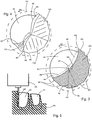
- Fig. 1 shows a lateral view as viewed perpendicular to the axis of rotation RA a milling tool according to the invention.
- the milling tool is designed as an end mill with a shank SC for clamping in a processing machine.
- On the shaft SC of the axially opposite tip of the milling tool a rounded radius cutting edge SR is formed, which allows the use of the milling tool as a radius cutter.
- the radius cutting edge SR is also referred to below as the first cutting edge.
- the axial section in which the radius cutting edge SR is effective is denoted by RB.
- a second cutting edge SW running around the rotational axis RA is formed on the tool.
- the second cutting edge SW preferably runs with a constant radius with respect to the axis of rotation RA.
- the enveloping rotational volume taken on rotation of the milling tool about the axis of rotation RA from the one-sectional cutting arrangement with the first cutting edge SR and the second cutting edge SW is shown in FIG Fig. 1 shown with a broken line.
- the rotation volume HV has in the longitudinal section WS the constant diameter DF.
- the formation of a constant diameter is of particular advantage, in particular with regard to the production of the tool, but is not mandatory.
- the diameter DF is, in particular at the transition to the tip region RB, not greater than 3 mm, in particular not greater than 2 mm.
- the rotation volume takes the form of a convexly curved body of revolution away from the milling tool.
- the axial regions RB and WB are referred to as the main body.
- the milling tool is preferably made of one piece material homogeneous.
- a main HZ in the form of a coiled recess with a coincident with the axis of rotation RA coil axis.
- the main pull HZ is formed in an advantageous embodiment over the entire work area formed by the longitudinal area WB and radius area RB of the main body of the milling tool with a constant cross section.
- the lateral, radially outwardly facing opening of the main pull HZ is limited by the coiled second cutting edge SW as an opening edge and a circumferentially opposite second edge RK, which is also referred to as the rear edge.
- Fig. 3 is enlarged a cross section through a milling tool of the type Fig. 1 shown with a sectional plane perpendicular to the axis of rotation RA in the region of the longitudinal section WB.
- the second cutting edge SW forms a pointing in the direction of rotation DR cutting edge, which with their distance RS the envelope of the rotational volume HV in the sectional plane of the Fig. 3 certainly.
- the rear edge KR runs coiled in a relation to the second cutting SW SW smaller radius RR from the axis of rotation DA.
- the following after the free surface FW peripheral surface of the milling tool, which is referred to as a lateral surface or as a rear surface extends approximately spirally with decreasing radius up to the rear edge KR.
- the recess forming the main pull HZ in the cross-section of the milling tool advantageously extends as in FIG Fig. 3 outlines approximately to the rotation axis RA and in a preferred embodiment by a small amount, which is advantageously not greater than 10% of the radius RS, beyond the axis of rotation.
- the body then has no core or soul.
- an undercut structure is formed, which has a plurality of circumferentially successive recesses MT and elevations ME.
- the elevations ME are preferably approximately on a spiral path from the cutting edge SW to the rear edge RK.
- the extent of the elevations ME in the circumferential direction is advantageously so small that the surface portion of the elevations ME on the lateral surface is at most 20%, in particular not more than 10%.
- the elevations ME in the lateral surface are substantially linear through the plane of the drawing Fig. 3 formed piercing.
- the depressions MT have a radial depression TN relative to the elevations ME, which is advantageously at least 1%, in particular at least 1.5% of the radius RS of the second cutting edge SW and at most 5%, in particular not more than 3% of the radius RS of the second cutting edge SW ,
- successive elevations ME are advantageously spaced by an angle WE of at least 15 °, in particular at least 20 ° from each other.
- the width of the recesses MT in the circumferential direction is advantageously less than 50 °, in particular less than 40 °, preferably less than 35 °, which is advantageous for a radial uniform support.
- the number of recesses is smaller for smaller cutting radii RS than for larger cutting radii.
- the cutting radii RS are advantageously not greater than 1.5 mm, in particular not greater than 1 mm, for the production of dental bodies.
- the elevations ME and depressions MT in the lateral surface of the milling tool facing away from the main pull HZ are in a preferred embodiment as shown in FIG Fig. 1 can be seen as coiled depressions formed against an envelope surface of the lateral surface. These depressions of the relief-grinding structure are also referred to below as side-draws NZ.
- the Maurat are preferably coiled with a coiled course of the second cutting edge SW same Wendelgang invented. Due to the approximately spirally extending envelope lines of the peripheral lines of the lateral surface, a greater helical pitch and a smaller radius than for the secondary blade near the second cutting edge SW results for the side branches near the rear edge KR. Due to the radius decreasing from the cutting edge SW to the back edge KR, the projection of the milling tool appears in the in Fig. 1 shown with a deviating from the envelope surface of the rotational volume DF conical course.
- the opening angle WE of the radially outwardly laterally outwardly facing opening of the main pull HZ is advantageously at least 110 °, in particular at least 130 °.
- the opening angle WH is not more than 180 °, in particular not more than 160 °.
- the area fraction of the main train HZ at the is advantageously at least 30%, in particular at least 40% of the circular area and advantageously at most 60%, in particular at most 50% of the circular area by the enveloping circle of the rotational volume HV specific cross-sectional area.
- a large chip thickness is given in particular by the radius difference of the rear edge KR against the second cutting edge SW.
- a high chip removal is advantageously favored by a small helix angle WD.
- Due to the incision-type design of the tool advantageously remains sufficient for the stability of the tool during milling operation material cross-sectional area MQ of the main body of the milling tool, which in Fig. 3 hatched.
- the plurality of recesses MT in the circumferential surface of the tool section in the longitudinal section WB advantageously causes a small contact surface of the tool with the thermoplastic material of the workpiece and thereby a low heat development.
- the relief grinding structure with the secondary draws NZ in the lateral surface of the longitudinal section WB of the milling tool can be produced in an advantageous embodiment by means of a grinding tool, wherein preferably in the production of the Maurat NZ same grinding tool can be used, which is also used for the production of Hauptzugs HZ.
- the control of the grinding tool for main train and side cables is advantageously easy.
- the approximately line-shaped coiled elevations of the relief grinding structure thereby automatically result as cutting lines of the curved grinding tool surfaces of the successively ground side cables.
- a freewheel FZ which in Fig. 1 is mostly obscured.
- Figure 4 is shown in an axial view of the tip of the milling tool, a preferred embodiment of the fingerschliffs FZ.
- the first edge SR which is against the plane of the drawing Fig. 4 arched, a first, the cutting edge of the first cutting edge approximately following free surface FR is assigned.
- FZ1 and FZ2 Farther away from the first cutting edge SR in the circumferential direction, there are free surfaces FZ1 and FZ2, which can be formed by flat surfaces in order to produce them in an advantageous manner.
- a further flank FZ3 is ground steeper against the direction of the axis of rotation directly on the main pull HZ than the flank faces FZ1 and FZ2. It turns out that the steeper cut of the further open space FZ3 advantageously favors the breaking off of material chips.
- the resulting from the intersection of the other free surface FZ3 with the main HZ edge in the end face is denoted by KF.
- the radius cutting edge SR as the first cutting edge of the single-cutting cutting arrangement extends from the second cutting edge SW forth in the view Fig. 4 curved towards the axis of rotation RA and spaced by a small amount radially from the axis of rotation at this past and by a small amount beyond this.
- Fig. 2 shows in longitudinal cut representation with against the plane of rotation twisted cutting plane another milling tool in Fig. 1 shown, in which example the helical pitch of the coiled structures is greater than in the example of Fig. 1 ,
- Out Fig. 2 clearly shows the course of the rotation axis RA with comprehensive Hauptzugs HZ.
- the free-edge FR is also clearly visible immediately behind the first edge SR and edge KF.
- Fig. 5 shows schematically the use of a milling tool WZ of the type described in the manufacture of dental bodies, such as dental crowns, from a thermoplastic or thermoplastic plastic workpiece WS. Due to the fine structures, in particular cavities in the dental bodies Z1, Z2 milling tools are required in relation to the diameter of great length.
- Fig. 5 shows an intermediate stage of the milling process, in which a part of the structures of the dental body Z1, Z2 are already created. The final contours are drawn with broken lines.
- a material removal by the milling tool FZ is carried out both by the radius cutting edge at the tip of the tool and by the coiled second cutting edge in the longitudinal region WB of the tool.
- the milling tool WZ is clamped in a receptacle of a drive device AE and driven in the milling operation with preferably more than 10,000 revolutions per minute.
Landscapes
- Health & Medical Sciences (AREA)
- Oral & Maxillofacial Surgery (AREA)
- Dentistry (AREA)
- Epidemiology (AREA)
- Life Sciences & Earth Sciences (AREA)
- Animal Behavior & Ethology (AREA)
- General Health & Medical Sciences (AREA)
- Public Health (AREA)
- Veterinary Medicine (AREA)
- Engineering & Computer Science (AREA)
- Mechanical Engineering (AREA)
- Dental Tools And Instruments Or Auxiliary Dental Instruments (AREA)
- Milling Processes (AREA)
Claims (22)
- Outil de fraisage (WZ) pour l'usinage à sec, sans fluide de refroidissement, de corps dentaires en matériau synthétique, en particulier en matériau chimioplastique ou thermoplastique (WS), avec un corps de base pouvant tourner autour d'un axe de rotation (RA) et allongé axialement sur une zone de travail (RB, WB), dans lequel- une gorge principale (HZ) est réalisée dans le corps de base sous la forme d'un creux hélicoïdal par rapport au volume de rotation (HV) occupé par l'outil de fraisage en rotation, laquelle définit dans le sens de la rotation une arête de coupe et une arête arrière (KR),- un arrangement de tranchants est réalisé à l'arête de coupe de la gorge principale (HZ), lequel comprend un premier tranchant (SR) sous la forme d'un tranchant à rayon à la pointe (RB) de l'outil de fraisage et se raccordant à celui-ci un deuxième tranchant (SW) en forme d'hélice autour d'une partie longitudinale (WB) du corps de base,- une première ou une deuxième face libre est associée au premier et au deuxième tranchant (SR, SW),- la surface latérale de la partie longitudinale (WB) présente une structure de goujure comportant une multiplicité de creux (MT) et d'élévations (ME), et- il est prévu à la pointe (RB), après la face libre (FR) suivant le contour de coupe du premier tranchant associé au premier tranchant, au moins une autre face polie libre (FZ1, FZ2, FZ3), dans laquelle la multiplicité de creux (MT) et d'élévations (ME) sont disposées de manière se succédant et hélicoïdale le long du rayon décroissant du deuxième tranchant (SW) au bord arrière (KR) avec un pas d'hélice égal au pas d'hélice du deuxième tranchant (SW) et un angle d'attaque hélicoïdal croissant, de sorte qu'une projection d'outil de fraisage (WZ) a un pas d'hélice différent de la surface enveloppe d'un volume rotatif (DF) .
- Outil de fraisage selon la revendication 1, caractérisé en ce que le creux formant la gorge principale (HZ) arrive radialement essentiellement jusqu'à l'axe de rotation (RA) et comprend de préférence celui-ci.
- Outil de fraisage selon la revendication 1 ou 2, caractérisé en ce que dans la partie longitudinale (WB) la proportion de surface de la gorge principale dans la surface de section transversale du volume de rotation (HV) vaut au moins 30 %, en particulier au moins 40 % et au maximum 60 %, en particulier au maximum 50 %.
- Outil de fraisage selon l'une quelconque des revendications 1 à 3, caractérisé en ce que l'ouverture latérale de la gorge principale dans la direction périphérique entre l'arête de coupe (SW) et l'arête arrière (KR) vaut au moins 110°, de préférence au moins 130°.
- Outil de fraisage selon l'une quelconque des revendications 1 à 4, caractérisé en ce que l'ouverture latérale de la gorge principale en direction périphérique vaut au maximum 180°, en particulier au maximum 160°.
- Outil de fraisage selon l'une quelconque des revendications 1 à 5, caractérisé en ce que la forme de la section transversale de la gorge principale (HZ) est identique dans la partie longitudinale (WB) et dans la pointe (RB).
- Outil de fraisage selon l'une quelconque des revendications 1 à 6, caractérisé en ce que l'arête arrière (KR) de l'ouverture latérale de la gorge principale (HZ) est d'au moins 10 %, en particulier d'au moins 20 %, plus proche de l'axe de rotation que le deuxième tranchant (SW) de l'arête de coupe.
- Outil de fraisage selon l'une quelconque des revendications 1 à 7, caractérisé en ce que la structure de goujure présente plusieurs creux (MT) et plusieurs élévations (ME) se succédant en direction périphérique.
- Outil de fraisage selon la revendication 8, caractérisé en ce que le nombre n d'élévations et de creux vaut respectivement au moins n = 4, en particulier au moins n = 6.
- Outil de fraisage selon la revendication 8 ou 9, caractérisé en ce que des élévations (ME) voisines en direction périphérique sont disposées en décalage l'une par rapport à l'autre d'un angle (WE) d'au moins 10°, de préférence d'au moins 15°.
- Outil de fraisage selon l'une quelconque des revendications 1 à 10, caractérisé en ce que la proportion de surface des élévations sur la surface latérale vaut au maximum 20 %, en particulier au maximum 10 %.
- Outil de fraisage selon la revendication 11, caractérisé en ce que les élévations se présentent essentiellement sous forme de lignes.
- Outil de fraisage selon l'une quelconque des revendications 1 à 12, caractérisé en ce que les creux sont enfoncés d'au maximum 5 %, en particulier d'au maximum 3 % du rayon du volume de rotation, radialement par rapport aux élévations voisines.
- Outil de fraisage selon l'une quelconque des revendications 1 à 13, caractérisé en ce que les creux (MT) sont enfoncés d'au moins 1 %, en particulier d'au moins 1,5 % du rayon du volume de rotation, radialement par rapport aux élévations voisines (ME).
- Outil de fraisage selon l'une quelconque des revendications 1 à 14, caractérisé en ce que les creux (MT) sont formés dans la surface latérale par plusieurs gorges secondaires (NZ) en forme d'hélice.
- Outil de fraisage selon la revendication 15, caractérisé en ce que les gorges secondaires (NZ) présentent le même pas d'hélice que le deuxième tranchant (SW).
- Outil de fraisage selon l'une quelconque des revendications 1 à 16, caractérisé en ce que le rayon de l'arrangement de tranchants vaut au maximum 1,5 mm.
- Outil de fraisage selon l'une quelconque des revendications 1 à 17, caractérisé en ce que la longueur axiale de l'arrangement de tranchants vaut au moins le triple de son diamètre maximal.
- Dispositif de fabrication de corps dentaires par usinage par fraisage à sec, sans fluide de refroidissement, d'une pièce en un matériau thermoplastique, avec un outil de fraisage selon l'une quelconque des revendications 1 à 18, pouvant tourner autour d'un axe de rotation et être déplacé dans les trois dimensions par rapport à la pièce.
- Procédé de fabrication de corps dentaires en matériau synthétique, caractérisé par l'utilisation d'un outil de fraisage (WZ) selon la revendication 1 pour l'usinage par fraisage à sec d'une pièce en matériau synthétique (WS) sans apport de fluide de refroidissement au point de fraisage.
- Procédé selon la revendication 20, caractérisé en ce que l'on choisit une pièce en un matériau thermoplastique ou chimioplastique.
- Procédé selon la revendication 20 ou 21, caractérisé en ce que l'outil de fraisage est entraîné à au moins 10 000 tours par minute.
Applications Claiming Priority (2)
| Application Number | Priority Date | Filing Date | Title |
|---|---|---|---|
| DE201120051863 DE202011051863U1 (de) | 2011-11-04 | 2011-11-04 | Fräswerkzeug und Vorrichtung mit einem solchen Fräswerkzeug für die Herstellung von Dentalkörpern |
| DE102012100508A DE102012100508A1 (de) | 2011-11-04 | 2012-01-23 | Fräswerkzeug, Vorrichtung mit einem solchen Fräswerkzeug und Verfahren für die Herstellung von Dentalkörpern |
Publications (3)
| Publication Number | Publication Date |
|---|---|
| EP2589452A1 EP2589452A1 (fr) | 2013-05-08 |
| EP2589452B1 EP2589452B1 (fr) | 2017-02-08 |
| EP2589452B3 true EP2589452B3 (fr) | 2019-11-13 |
Family
ID=47142987
Family Applications (1)
| Application Number | Title | Priority Date | Filing Date |
|---|---|---|---|
| EP12190885.9A Active EP2589452B3 (fr) | 2011-11-04 | 2012-10-31 | Outil de fraisage, dispositif doté d'un tel outil de fraisage et procédé de fabrication de corps dentaires |
Country Status (2)
| Country | Link |
|---|---|
| EP (1) | EP2589452B3 (fr) |
| DE (1) | DE102012100508A1 (fr) |
Families Citing this family (3)
| Publication number | Priority date | Publication date | Assignee | Title |
|---|---|---|---|---|
| DE102014203450B4 (de) * | 2014-02-26 | 2024-10-10 | Gebr. Brasseler Gmbh & Co. Kg | Dentalinstrument |
| DE202017101382U1 (de) * | 2017-03-10 | 2017-03-30 | Hptec Gmbh | Fräswerkzeug |
| LU100689B1 (de) * | 2018-01-26 | 2019-08-21 | Datron Ag | Fräswerkzeug |
Family Cites Families (4)
| Publication number | Priority date | Publication date | Assignee | Title |
|---|---|---|---|---|
| DD289231A5 (de) * | 1989-11-29 | 1991-04-25 | Forschungszentrum Der Werkzeugindustrie,De | Werkzeug fuer holz- und plastbearbeitung |
| US6164876A (en) * | 1999-10-30 | 2000-12-26 | Tungsten Industries, Inc | Cutting tool |
| DE20105015U1 (de) * | 2001-03-22 | 2001-07-19 | Busch & CO. KG, 51766 Engelskirchen | Rotierendes spanabhebendes Fräswerkzeug |
| CA2798110C (fr) * | 2010-04-30 | 2018-02-20 | Robert Bosch Gmbh | Foret multifonctions a cannelure o |
-
2012
- 2012-01-23 DE DE102012100508A patent/DE102012100508A1/de not_active Withdrawn
- 2012-10-31 EP EP12190885.9A patent/EP2589452B3/fr active Active
Also Published As
| Publication number | Publication date |
|---|---|
| EP2589452B1 (fr) | 2017-02-08 |
| DE102012100508A1 (de) | 2013-05-08 |
| EP2589452A1 (fr) | 2013-05-08 |
Similar Documents
| Publication | Publication Date | Title |
|---|---|---|
| DE112007003489B4 (de) | Spiralgewindebohrer | |
| EP1864737B1 (fr) | Outil d'usinage par enlevement de copeaux | |
| EP2403673B2 (fr) | Fraise à queue | |
| EP1131012B1 (fr) | Instrument pour canal radiculaire et procede permettant de le produire | |
| EP1669149B1 (fr) | Outil et procédé pour produire un pas de vis dans une pièce | |
| EP3157700B1 (fr) | Outil de coupe à rotation | |
| WO2016020047A1 (fr) | Outil de fraisage | |
| EP3797911B1 (fr) | Fraise à queue et son procédé de fabrication | |
| DE102005022503B4 (de) | Werkzeug und Verfahren zur Erzeugung eines Gewindes | |
| EP2589452B3 (fr) | Outil de fraisage, dispositif doté d'un tel outil de fraisage et procédé de fabrication de corps dentaires | |
| DE112008004051T5 (de) | Spiralgewindebohrer | |
| DE102008030100B4 (de) | Gewindefräser | |
| DE102021105703B4 (de) | Bohrwerkzeug und Verfahren zum Erzeugen einer Bohrung | |
| DE102007060554A1 (de) | Verfahren und Werkzeug zur Erzeugung eines Außengewindes | |
| DE112006004174T5 (de) | Spiralnut-Gewindeschneider | |
| EP3517235B1 (fr) | Procédé d'ébarbage de pignons conique et machine à tailler les engrenages cnc pourvue d'un logiciel d'ébarbage correspondant | |
| EP3507044B1 (fr) | Outil de fraisage à un seul tranchant | |
| EP1958589A1 (fr) | Fraise dentaire | |
| DE202011051863U1 (de) | Fräswerkzeug und Vorrichtung mit einem solchen Fräswerkzeug für die Herstellung von Dentalkörpern | |
| WO2023213816A1 (fr) | Foret étagé | |
| DE102004040580B4 (de) | Fräser | |
| DE102005037309B4 (de) | Werkzeug und Verfahren zur Erzeugung oder Nachbearbeitung eines Gewindes | |
| EP0432621A2 (fr) | Fraise à couper des filetages | |
| DE102010027496B4 (de) | Fräswerkzeug | |
| EP3804906B1 (fr) | Procédé de fabrication d'une géométrie de coupe coté extérieur dans un outil à tige de matériau plein destiné au traitement des matériaux |
Legal Events
| Date | Code | Title | Description |
|---|---|---|---|
| PUAI | Public reference made under article 153(3) epc to a published international application that has entered the european phase |
Free format text: ORIGINAL CODE: 0009012 |
|
| AK | Designated contracting states |
Kind code of ref document: A1 Designated state(s): AL AT BE BG CH CY CZ DE DK EE ES FI FR GB GR HR HU IE IS IT LI LT LU LV MC MK MT NL NO PL PT RO RS SE SI SK SM TR |
|
| AX | Request for extension of the european patent |
Extension state: BA ME |
|
| 17P | Request for examination filed |
Effective date: 20131108 |
|
| RBV | Designated contracting states (corrected) |
Designated state(s): AL AT BE BG CH CY CZ DE DK EE ES FI FR GB GR HR HU IE IS IT LI LT LU LV MC MK MT NL NO PL PT RO RS SE SI SK SM TR |
|
| GRAP | Despatch of communication of intention to grant a patent |
Free format text: ORIGINAL CODE: EPIDOSNIGR1 |
|
| INTG | Intention to grant announced |
Effective date: 20160826 |
|
| GRAS | Grant fee paid |
Free format text: ORIGINAL CODE: EPIDOSNIGR3 |
|
| GRAA | (expected) grant |
Free format text: ORIGINAL CODE: 0009210 |
|
| AK | Designated contracting states |
Kind code of ref document: B1 Designated state(s): AL AT BE BG CH CY CZ DE DK EE ES FI FR GB GR HR HU IE IS IT LI LT LU LV MC MK MT NL NO PL PT RO RS SE SI SK SM TR |
|
| REG | Reference to a national code |
Ref country code: GB Ref legal event code: FG4D Free format text: NOT ENGLISH |
|
| REG | Reference to a national code |
Ref country code: CH Ref legal event code: EP Ref country code: AT Ref legal event code: REF Ref document number: 866645 Country of ref document: AT Kind code of ref document: T Effective date: 20170215 |
|
| REG | Reference to a national code |
Ref country code: IE Ref legal event code: FG4D Free format text: LANGUAGE OF EP DOCUMENT: GERMAN |
|
| REG | Reference to a national code |
Ref country code: DE Ref legal event code: R096 Ref document number: 502012009491 Country of ref document: DE |
|
| REG | Reference to a national code |
Ref country code: LT Ref legal event code: MG4D |
|
| REG | Reference to a national code |
Ref country code: NL Ref legal event code: MP Effective date: 20170208 |
|
| PG25 | Lapsed in a contracting state [announced via postgrant information from national office to epo] |
Ref country code: GR Free format text: LAPSE BECAUSE OF FAILURE TO SUBMIT A TRANSLATION OF THE DESCRIPTION OR TO PAY THE FEE WITHIN THE PRESCRIBED TIME-LIMIT Effective date: 20170509 Ref country code: NO Free format text: LAPSE BECAUSE OF FAILURE TO SUBMIT A TRANSLATION OF THE DESCRIPTION OR TO PAY THE FEE WITHIN THE PRESCRIBED TIME-LIMIT Effective date: 20170508 Ref country code: FI Free format text: LAPSE BECAUSE OF FAILURE TO SUBMIT A TRANSLATION OF THE DESCRIPTION OR TO PAY THE FEE WITHIN THE PRESCRIBED TIME-LIMIT Effective date: 20170208 Ref country code: HR Free format text: LAPSE BECAUSE OF FAILURE TO SUBMIT A TRANSLATION OF THE DESCRIPTION OR TO PAY THE FEE WITHIN THE PRESCRIBED TIME-LIMIT Effective date: 20170208 Ref country code: LT Free format text: LAPSE BECAUSE OF FAILURE TO SUBMIT A TRANSLATION OF THE DESCRIPTION OR TO PAY THE FEE WITHIN THE PRESCRIBED TIME-LIMIT Effective date: 20170208 |
|
| PG25 | Lapsed in a contracting state [announced via postgrant information from national office to epo] |
Ref country code: LV Free format text: LAPSE BECAUSE OF FAILURE TO SUBMIT A TRANSLATION OF THE DESCRIPTION OR TO PAY THE FEE WITHIN THE PRESCRIBED TIME-LIMIT Effective date: 20170208 Ref country code: PT Free format text: LAPSE BECAUSE OF FAILURE TO SUBMIT A TRANSLATION OF THE DESCRIPTION OR TO PAY THE FEE WITHIN THE PRESCRIBED TIME-LIMIT Effective date: 20170608 Ref country code: SE Free format text: LAPSE BECAUSE OF FAILURE TO SUBMIT A TRANSLATION OF THE DESCRIPTION OR TO PAY THE FEE WITHIN THE PRESCRIBED TIME-LIMIT Effective date: 20170208 Ref country code: RS Free format text: LAPSE BECAUSE OF FAILURE TO SUBMIT A TRANSLATION OF THE DESCRIPTION OR TO PAY THE FEE WITHIN THE PRESCRIBED TIME-LIMIT Effective date: 20170208 Ref country code: ES Free format text: LAPSE BECAUSE OF FAILURE TO SUBMIT A TRANSLATION OF THE DESCRIPTION OR TO PAY THE FEE WITHIN THE PRESCRIBED TIME-LIMIT Effective date: 20170208 Ref country code: NL Free format text: LAPSE BECAUSE OF FAILURE TO SUBMIT A TRANSLATION OF THE DESCRIPTION OR TO PAY THE FEE WITHIN THE PRESCRIBED TIME-LIMIT Effective date: 20170208 Ref country code: BG Free format text: LAPSE BECAUSE OF FAILURE TO SUBMIT A TRANSLATION OF THE DESCRIPTION OR TO PAY THE FEE WITHIN THE PRESCRIBED TIME-LIMIT Effective date: 20170508 |
|
| REG | Reference to a national code |
Ref country code: FR Ref legal event code: PLFP Year of fee payment: 6 |
|
| PG25 | Lapsed in a contracting state [announced via postgrant information from national office to epo] |
Ref country code: SK Free format text: LAPSE BECAUSE OF FAILURE TO SUBMIT A TRANSLATION OF THE DESCRIPTION OR TO PAY THE FEE WITHIN THE PRESCRIBED TIME-LIMIT Effective date: 20170208 Ref country code: EE Free format text: LAPSE BECAUSE OF FAILURE TO SUBMIT A TRANSLATION OF THE DESCRIPTION OR TO PAY THE FEE WITHIN THE PRESCRIBED TIME-LIMIT Effective date: 20170208 Ref country code: RO Free format text: LAPSE BECAUSE OF FAILURE TO SUBMIT A TRANSLATION OF THE DESCRIPTION OR TO PAY THE FEE WITHIN THE PRESCRIBED TIME-LIMIT Effective date: 20170208 Ref country code: CZ Free format text: LAPSE BECAUSE OF FAILURE TO SUBMIT A TRANSLATION OF THE DESCRIPTION OR TO PAY THE FEE WITHIN THE PRESCRIBED TIME-LIMIT Effective date: 20170208 |
|
| REG | Reference to a national code |
Ref country code: DE Ref legal event code: R097 Ref document number: 502012009491 Country of ref document: DE |
|
| PG25 | Lapsed in a contracting state [announced via postgrant information from national office to epo] |
Ref country code: PL Free format text: LAPSE BECAUSE OF FAILURE TO SUBMIT A TRANSLATION OF THE DESCRIPTION OR TO PAY THE FEE WITHIN THE PRESCRIBED TIME-LIMIT Effective date: 20170208 Ref country code: DK Free format text: LAPSE BECAUSE OF FAILURE TO SUBMIT A TRANSLATION OF THE DESCRIPTION OR TO PAY THE FEE WITHIN THE PRESCRIBED TIME-LIMIT Effective date: 20170208 Ref country code: SM Free format text: LAPSE BECAUSE OF FAILURE TO SUBMIT A TRANSLATION OF THE DESCRIPTION OR TO PAY THE FEE WITHIN THE PRESCRIBED TIME-LIMIT Effective date: 20170208 |
|
| PLBE | No opposition filed within time limit |
Free format text: ORIGINAL CODE: 0009261 |
|
| 26N | No opposition filed |
Effective date: 20171109 |
|
| PG25 | Lapsed in a contracting state [announced via postgrant information from national office to epo] |
Ref country code: SI Free format text: LAPSE BECAUSE OF FAILURE TO SUBMIT A TRANSLATION OF THE DESCRIPTION OR TO PAY THE FEE WITHIN THE PRESCRIBED TIME-LIMIT Effective date: 20170208 |
|
| PG25 | Lapsed in a contracting state [announced via postgrant information from national office to epo] |
Ref country code: MC Free format text: LAPSE BECAUSE OF FAILURE TO SUBMIT A TRANSLATION OF THE DESCRIPTION OR TO PAY THE FEE WITHIN THE PRESCRIBED TIME-LIMIT Effective date: 20170208 |
|
| REG | Reference to a national code |
Ref country code: CH Ref legal event code: PL |
|
| REG | Reference to a national code |
Ref country code: IE Ref legal event code: MM4A |
|
| PG25 | Lapsed in a contracting state [announced via postgrant information from national office to epo] |
Ref country code: LU Free format text: LAPSE BECAUSE OF NON-PAYMENT OF DUE FEES Effective date: 20171031 Ref country code: CH Free format text: LAPSE BECAUSE OF NON-PAYMENT OF DUE FEES Effective date: 20171031 Ref country code: LI Free format text: LAPSE BECAUSE OF NON-PAYMENT OF DUE FEES Effective date: 20171031 |
|
| REG | Reference to a national code |
Ref country code: BE Ref legal event code: MM Effective date: 20171031 |
|
| PG25 | Lapsed in a contracting state [announced via postgrant information from national office to epo] |
Ref country code: BE Free format text: LAPSE BECAUSE OF NON-PAYMENT OF DUE FEES Effective date: 20171031 |
|
| PG25 | Lapsed in a contracting state [announced via postgrant information from national office to epo] |
Ref country code: MT Free format text: LAPSE BECAUSE OF FAILURE TO SUBMIT A TRANSLATION OF THE DESCRIPTION OR TO PAY THE FEE WITHIN THE PRESCRIBED TIME-LIMIT Effective date: 20170208 |
|
| REG | Reference to a national code |
Ref country code: FR Ref legal event code: PLFP Year of fee payment: 7 |
|
| PG25 | Lapsed in a contracting state [announced via postgrant information from national office to epo] |
Ref country code: IE Free format text: LAPSE BECAUSE OF NON-PAYMENT OF DUE FEES Effective date: 20171031 |
|
| REG | Reference to a national code |
Ref country code: AT Ref legal event code: MM01 Ref document number: 866645 Country of ref document: AT Kind code of ref document: T Effective date: 20171031 |
|
| PG25 | Lapsed in a contracting state [announced via postgrant information from national office to epo] |
Ref country code: AT Free format text: LAPSE BECAUSE OF NON-PAYMENT OF DUE FEES Effective date: 20171031 |
|
| PG25 | Lapsed in a contracting state [announced via postgrant information from national office to epo] |
Ref country code: HU Free format text: LAPSE BECAUSE OF FAILURE TO SUBMIT A TRANSLATION OF THE DESCRIPTION OR TO PAY THE FEE WITHIN THE PRESCRIBED TIME-LIMIT; INVALID AB INITIO Effective date: 20121031 |
|
| REG | Reference to a national code |
Ref country code: DE Ref legal event code: R055 Ref document number: 502012009491 Country of ref document: DE |
|
| PLCP | Request for limitation filed |
Free format text: ORIGINAL CODE: EPIDOSNLIM1 |
|
| PLCQ | Request for limitation of patent found admissible |
Free format text: ORIGINAL CODE: 0009231 |
|
| LIM1 | Request for limitation found admissible |
Free format text: SEQUENCE NO: 1; FILED AFTER OPPOSITION PERIOD Filing date: 20190710 Effective date: 20190710 |
|
| REG | Reference to a national code |
Ref country code: DE Ref legal event code: R056 Ref document number: 502012009491 Country of ref document: DE |
|
| PLCR | Communication despatched that request for limitation of patent was allowed |
Free format text: ORIGINAL CODE: 0009245 |
|
| PLCN | Payment of fee for limitation of patent |
Free format text: ORIGINAL CODE: EPIDOSNRAL3 |
|
| PUAM | (expected) publication of b3 document |
Free format text: ORIGINAL CODE: 0009410 |
|
| STAA | Information on the status of an ep patent application or granted ep patent |
Free format text: STATUS: THE PATENT HAS BEEN LIMITED |
|
| PG25 | Lapsed in a contracting state [announced via postgrant information from national office to epo] |
Ref country code: CY Free format text: LAPSE BECAUSE OF NON-PAYMENT OF DUE FEES Effective date: 20170208 |
|
| PG25 | Lapsed in a contracting state [announced via postgrant information from national office to epo] |
Ref country code: MK Free format text: LAPSE BECAUSE OF FAILURE TO SUBMIT A TRANSLATION OF THE DESCRIPTION OR TO PAY THE FEE WITHIN THE PRESCRIBED TIME-LIMIT Effective date: 20170208 |
|
| REG | Reference to a national code |
Ref country code: DE Ref legal event code: R008 Ref document number: 502012009491 Country of ref document: DE Ref country code: DE Ref legal event code: R039 Ref document number: 502012009491 Country of ref document: DE |
|
| PG25 | Lapsed in a contracting state [announced via postgrant information from national office to epo] |
Ref country code: AL Free format text: LAPSE BECAUSE OF FAILURE TO SUBMIT A TRANSLATION OF THE DESCRIPTION OR TO PAY THE FEE WITHIN THE PRESCRIBED TIME-LIMIT Effective date: 20170208 Ref country code: IS Free format text: LAPSE BECAUSE OF FAILURE TO SUBMIT A TRANSLATION OF THE DESCRIPTION OR TO PAY THE FEE WITHIN THE PRESCRIBED TIME-LIMIT Effective date: 20170608 |
|
| REG | Reference to a national code |
Ref country code: DE Ref legal event code: R040 Ref document number: 502012009491 Country of ref document: DE |
|
| PGFP | Annual fee paid to national office [announced via postgrant information from national office to epo] |
Ref country code: GB Payment date: 20211022 Year of fee payment: 10 Ref country code: TR Payment date: 20211026 Year of fee payment: 10 |
|
| PGFP | Annual fee paid to national office [announced via postgrant information from national office to epo] |
Ref country code: IT Payment date: 20211029 Year of fee payment: 10 Ref country code: FR Payment date: 20211021 Year of fee payment: 10 |
|
| GBPC | Gb: european patent ceased through non-payment of renewal fee |
Effective date: 20221031 |
|
| PG25 | Lapsed in a contracting state [announced via postgrant information from national office to epo] |
Ref country code: FR Free format text: LAPSE BECAUSE OF NON-PAYMENT OF DUE FEES Effective date: 20221031 |
|
| PG25 | Lapsed in a contracting state [announced via postgrant information from national office to epo] |
Ref country code: IT Free format text: LAPSE BECAUSE OF NON-PAYMENT OF DUE FEES Effective date: 20221031 Ref country code: GB Free format text: LAPSE BECAUSE OF NON-PAYMENT OF DUE FEES Effective date: 20221031 |
|
| PGFP | Annual fee paid to national office [announced via postgrant information from national office to epo] |
Ref country code: DE Payment date: 20251031 Year of fee payment: 14 |