EP2589851A2 - Pompe de registre - Google Patents
Pompe de registre Download PDFInfo
- Publication number
- EP2589851A2 EP2589851A2 EP12007478.6A EP12007478A EP2589851A2 EP 2589851 A2 EP2589851 A2 EP 2589851A2 EP 12007478 A EP12007478 A EP 12007478A EP 2589851 A2 EP2589851 A2 EP 2589851A2
- Authority
- EP
- European Patent Office
- Prior art keywords
- pump
- oil
- pressure
- valve
- register
- Prior art date
- Legal status (The legal status is an assumption and is not a legal conclusion. Google has not performed a legal analysis and makes no representation as to the accuracy of the status listed.)
- Withdrawn
Links
Images


Classifications
-
- F—MECHANICAL ENGINEERING; LIGHTING; HEATING; WEAPONS; BLASTING
- F01—MACHINES OR ENGINES IN GENERAL; ENGINE PLANTS IN GENERAL; STEAM ENGINES
- F01M—LUBRICATING OF MACHINES OR ENGINES IN GENERAL; LUBRICATING INTERNAL COMBUSTION ENGINES; CRANKCASE VENTILATING
- F01M1/00—Pressure lubrication
- F01M1/02—Pressure lubrication using lubricating pumps
-
- F—MECHANICAL ENGINEERING; LIGHTING; HEATING; WEAPONS; BLASTING
- F01—MACHINES OR ENGINES IN GENERAL; ENGINE PLANTS IN GENERAL; STEAM ENGINES
- F01M—LUBRICATING OF MACHINES OR ENGINES IN GENERAL; LUBRICATING INTERNAL COMBUSTION ENGINES; CRANKCASE VENTILATING
- F01M1/00—Pressure lubrication
- F01M1/12—Closed-circuit lubricating systems not provided for in groups F01M1/02 - F01M1/10
- F01M2001/123—Closed-circuit lubricating systems not provided for in groups F01M1/02 - F01M1/10 using two or more pumps
-
- F—MECHANICAL ENGINEERING; LIGHTING; HEATING; WEAPONS; BLASTING
- F01—MACHINES OR ENGINES IN GENERAL; ENGINE PLANTS IN GENERAL; STEAM ENGINES
- F01M—LUBRICATING OF MACHINES OR ENGINES IN GENERAL; LUBRICATING INTERNAL COMBUSTION ENGINES; CRANKCASE VENTILATING
- F01M1/00—Pressure lubrication
- F01M1/12—Closed-circuit lubricating systems not provided for in groups F01M1/02 - F01M1/10
- F01M2001/126—Dry-sumps
Definitions
- the invention relates to a register pump, that is, a multi-stage pump having at least two individual pumps with a common drive. Each of these individual pumps has a valve device.
- Multistage pumps are also used, for example, as so-called dry sump pumps for the lubricating oil supply of internal combustion engines, a first pump performing the pressure oil supply as a pressure stage and at least a second pump serving as a suction stage for safe oil extraction from the oil sump.
- a pump with two different media to be pumped is also referred to as a tandem pump, wherein, for example, the first pump is designed as a lubricating oil pump of an internal combustion engine and the second pump as a vacuum pump for the vacuum supply of a brake booster from an associated motor vehicle.
- Control oil pumps are used, which have a continuous flow control and can vary depending on the need also the oil pressure, so that a correspondingly low pump drive power results. They can be designed as gear pumps, as vane pumps or as pendulum slide pumps.
- reversible multi-stage pumps can also be used to supply lubricating oil to internal combustion engines. In this case, with sufficient lubricating oil supply of the internal combustion engine by the first pump, the second pump is then short-circuited via a valve and their delivery oil pressure-less returned to the suction side, which reduces their drive power accordingly.
- the DE 102011008362 A1 describes a two-stage pump in which the first pump performs the lubricating oil supply of an internal combustion engine, while the second pump supports both the supply of lubricating oil as needed or also ensures the pressure supply of a pressure accumulator having a hydraulic pressure system.
- the PCT / DE 20111000014 describes a multi-stage pump in which a first and a second pump have a switchable coupling between them.
- An electric motor driving the drive is connected to the first pump via a first drive shaft, while the clutch for switching off the second pump is actuated by a hydraulically or electrically axially movable second drive shaft.
- the DE 19935781 A1 describes a two-stage pump with a common drive of a first pump and a second pump for supplying an internal combustion engine with oil under oil pressure. Each pump is provided against the force of a spring applied valve for controlling the oil pressure by partial or complete discharge of the oil flow of each pump.
- the DE 102 37 801 C5 describes a control oil pump in which a two-stage control piston regulates the oil pressure as needed switchable to two different pressure values. By acting as a pressure sensor control piston, the respective oil pressure can always be kept precisely at the respective pressure level, regardless of the operation-dependent changing oil flow rate.
- a pump module having a common drive of an oil pump as a first pump and a vacuum pump as a second pump is known.
- the DE 10 2011 114 893 A1 describes a tandem pump in which an oil pump is permanently driven and a vacuum pump is switched on by a separating clutch, if necessary.
- the DE 10 2005 015 721 B3 describes a vacuum pump for generating negative pressure, in which a radially slidably mounted in a rotor wing is guided radially in an eccentric to the rotor formed pump housing.
- the volumes located on both sides of the vane change periodically with the rotor rotation, so that a pumping effect for a gas to be delivered by the vacuum pump takes place.
- the well-known, multi-stage pumps are designed with a first and at least one second pump, either exercise different functions or allow for the same function of the two pumps, for example, two pressure pumps for a hydraulic system, a demand-dependent shutdown of the effective flow rate of the second pump and thus Save drive power.
- a switchable clutch for decommissioning of the pump can be used, which increases the space and causes corresponding additional costs.
- the flow rate of the second pump instead of the hydraulic system can also be fed back without pressure to the suction side at then reduced drive power of the second pump.
- regulating oil pumps only deliver the necessary to generate the required oil pressure flow and require a correspondingly low drive power, but they are due to the continuous control of the flow rate and a complex pressure control accordingly costly.
- the invention is based on the object, a solution for the adjustment of the effective flow rate of a plurality of, in particular non-adjustable, pumps to find existing register pump, which lowers the drive power with little effort.
- An advantage of the register pump according to the invention is that the second pump either generates an underpressure or a vacuum in the suction channel when the oil supply is interrupted or draws in a gas. This reduces the drive power of the second pump.
- the first pump is understood to be an independent unit within the register pump which permanently pumps oil and has a valve for regulating the oil pressure.
- the second pump still a third, a fourth, or more
- the second pump has a Gaszu 1500kanal and a gas supply valve, via which with the second pump, a gas is conveyed at interrupted oil production.
- the gas supply valve is designed as a check valve so that gas, in particular air, can flow on the suction side only to the second pump.
- the gas supply valve comprises a pressure sensor and is switched so that it only opens when there is a lower pressure on the pump side of the gas supply than on the inflow side.
- the register pump comprises a control unit having a control pressure line and a regulator.
- a control pressure set by the regulator in the control pressure line preferably acts on all valves of the register pump in order to regulate the oil pressure via the oil flow and, if appropriate, switch the oil flow of the second pump and further pumps off or on.
- valves of the individual pumps each include a spring acting counter to the control pressure, so that a respectively associated valve piston can be displaced by increasing the control pressure.
- rule and control are used interchangeably, although both a pure control, that is, no feedback signal is generated, and a rule, that is, a feedback control, respectively meant.
- the controller comprises a control piston for generating the control pressure.
- the regulator is connected to the pressure line so that oil can enter the regulator with oil pressure, wherein the controller is also connected to a low pressure side, which has a much lower oil pressure, in particular the ambient pressure.
- the regulator for example in the case of a proportional valve or an adjustable throttle, varies the mean flow resistance experienced by the oil flowing from the pressure side to the low pressure side, so that the regulating pressure is established.
- the register pump comprises a third pump, which comprises a third suction channel, a third pressure channel, a drivable third drive wheel arranged by the drive shaft and a third valve, by means of which an oil flow of the third pump is controllable and also interruptible. It is particularly favorable if the third valve is designed such that it first opens before the second valve of the second pump begins to open. In other words, the control of the oil pressure by derivation of the oil flow of the individual pumps to turn off the flow of oil according to the invention by the pump associated with each valve valves depending on the pressure in dependence on the control pressure in succession.
- the first pump is designed as a variable displacement pump with variable oil delivery, as so-called.
- Regular oil pump Although the structure of the register pump is thus more complex, it is possible, thereby further reducing the energy consumption of the register pump.
- the first feed wheel of the first pump preferably meshes with a first co-feed wheel, the second feed wheel of the second pump with a second co-feed wheel, and an optionally present third feed wheel of a third pump with a third co-feed wheel.
- the partial use of form-fitting torque-transmitting connectors is advantageous, whereby a good mountability of the register pump is given.
- the register pump according to the invention preferably serves the lubricating oil supply of an internal combustion engine.
- the internal combustion engine comprises a vacuum reservoir connected to the gas supply passage of the second pump so that the second pump evacuates the vacuum reservoir when the second valve has shut off the oil flow and the second pump generates negative pressure.
- the second pump acts as a negative pressure generating support of the switchable vacuum pump so that it can be turned off more frequently when the second pump does not deliver oil. This lowers the energy consumption of the register pump.
- the first pump, the second pump and optionally further pumps are preferably external gear pumps.
- the invention is not limited to such pumps, for example, the pumps may also be internal gear pumps, vane pumps, rotary vane pumps or piston pumps. It is also possible that the pumps have different designs among each other.
- the oil pressure generated by the always pumping oil first pump is used for lubrication of all bearings of the multi-stage pump, the exiting from the bearings oil lubricates shut off oil production or gas production of the second pump whose delivery wheels and seals them well due to oil film wetting.
- the required for the engine to be supplied oil pressure can be controlled by the respective valves of the individual pumps of the register pump in the simplest case only hydraulically. While the valve of the always oil-conveying first pump then has to ensure a relatively high oil pressure level for, for example, high engine speeds, the second shut-off pump valve can set a sufficiently low oil pressure level at low engine speeds.
- the monitoring of the oil supply of the internal combustion engine and the control and switching of the individual pumps of the register pump by a controller as well as the monitoring of a supplied from the register pump vacuum system is preferably carried out by the control unit of the internal combustion engine.
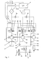
- FIG. 1 shows a schematic representation of a register pump 1 according to the invention, which serves in this application example, the supply of an internal combustion engine 2 with lubricating oil.
- the internal combustion engine 2 drives a shaft 3 of the register pump 1, which has a first pump 10, a second pump 20 and a third pump 30.
- the register pump 1 sucks oil from an oil pan 4 of the internal combustion engine 2 and conveys it via a filter 5 and a pressure line 6 under oil pressure p 6 to the internal combustion engine 2.
- the oil delivered by the pumps 20 and 30 flows before the filter 5 through a first check valve 5a or through a second check valve 5b.
- each of the three pumps 10, 20 and 30 each have a suction channel 14, 24 and 34.
- a valve 16, 26 and 36 is respectively arranged on a pressure channel 15, 25 and 35.
- the pump 10, 20 and 30 connected to either the filter 5 or a pressure sink, for example, at too high oil pressure in the pressure line 6 to the engine part of the oil flow to the suction port 14 or derive the oil pan 4.
- valves 16, 26 and 36 either directly with oil pressure or preferably via a connected to the pressure line 6 controller 7 via a control pressure line 8 with a control pressure p 8 are applied.
- the controller 7 has a not shown oil pressure sensor for detecting the oil pressure p 6 and regulates the control pressure p 8 so that the oil pressure p 6 corresponds to a target oil pressure p 6, target .
- ECU Electronic Control Unit
- control pressure p 8 has completely filled only the valve 36 fitted with the weakest spring 38 and connected the pressure channel 35 to the oil sump 4.
- the valve 36 has also disconnected the connection of the suction channel 34 to the suction channel 14 and thus the oil suction and the oil delivery of the pump 30 from the oil pan 4.
- the controller 7 increases the control pressure p 8 in the control pressure line 8, whereby then the valve 26 of the pump 20 partially or completely whose oil flow to the oil pan 4 redirects or as in the case of pump 30 shuts off at a dependent on the oil pressure p 6 in the pressure line 6 further from the controller 7 increased control pressure p 8 controls Finally, even the valve 16 of the pump 10 whose oil flow partially to the suction port 14 to.
- the vacuum system 9 can, for example, supply a brake booster 90 of a motor vehicle driven by the internal combustion engine 2.
- a brake booster 90 of a motor vehicle driven by the internal combustion engine 2.
- it is connected via two gas supply valves, in the present case via a check valve 92 and a check valve 94, to the register pump 1 and has a switching valve 95.
- An additional memory 96 which is connected via an electric valve 97, secures at not enough by oil extraction of the pump 20 and / or the pump 30 air extraction from the vacuum system 9, the functionality of the brake booster 90th
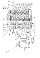
- FIG. 2 shows an inventive embodiment of a three-stage with external gears register pump 1 for lubricating oil supply of the internal combustion engine 2 is not shown in a longitudinal section, corresponding to the section AA of FIG. 3 ,
- the first pump 10 with a housing 11 has a first conveyor gear 12, which with a behind the cutting plane of FIG. 2 lying and therefore not visible first co-conveying gear 13 is in meshing engagement.
- the driven by the engine via a drive wheel and the shaft 3 feed gears 12 and 13 suck on the suction port 14 from the oil pan 4 oil and press it via the pressure channel 15, the valve 16, the filter 5 and the pressure line 6 under oil pressure to the engine. 2 ,
- the pump 20 with a housing 21, which is flanged to the pump 10, has on the shaft 3, a feed gear 22 and a meshing with this, not visible behind the cutting plane located co-feed gear 23.
- the two conveyor gears 22 and 23 suck from the suction channel 24, the oil to be pumped and push it via the pressure channel 25 to the valve 26.
- the oil pumped by the pump 20 flows through a pressure bore 50 and the check valve 5a on to the pump 10 and from there together with the pumped by the pump 10 oil in the pressure line 6.
- the pump 20 is at ⁇ lansaugung with its suction channel 24 via a plurality of connecting channels 27 and 17, and their in FIG. 2 invisible connection via the valve 26, with the suction channel 14 of the pump 10 in conjunction.
- the pump 30 is flanged with its housing 31 to the pump 20. It sucks in the position shown of the valve 36 with a feed gear 32 and a non-visible Co-feed gear 33 via the suction channel 34, a connecting channel 37 and the connecting channel 17 similar to the pump 20 oil from the oil pan 4.
- the conveyed oil passes via the pressure channel 35 and the correspondingly positioned valve 36 as well as via the pressure bore 50 connecting the all pumps 10, 20 and 30 and the check valve 5b to the pressure line 6.
- a cover 30 closing the pump 30 supports in its housing 41 the conveyor gears 12, 22 and 32 receiving shaft third
- the vacuum system 9 is connected to the brake booster 90 at the intake ports 24 and 34.
- a line 91 and a line 93 which serve as gas supply channels, the check valve 92 and the check valve 94 are arranged.
- the switching valve 95 is arranged in the inflow upstream of the check valves 92, 94.
- the switching valve 95 can be switched at sufficiently high in the brake booster 90 and the vacuum reservoir 96 stored vacuum level, and then to ventilate the suction channels 24 and 34.
- at least one vacuum relief valve 98 may also be connected to the pumps 20 and 30 which are operated when the oil flow is switched off. When conveying the air pump 20 and 30 switched off by the flow of oil, the conveyed air is returned to the area of the oil sump 4.
- All bearings of the register pump 1 are lubricated with oil pressure from the pressure channel 15 of the pump 10 via pressure connections in the housing 11, in the shaft 3 or in other waves, wherein from the bearings leaking oil and the lubrication of the conveyor gears 22, 23, 32 and 34th with switched off oil delivery of the pumps 20 and 30 ensures.
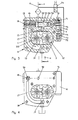
- FIG. 3 shows a cross section through the housing 11 of the pump 10.
- the fixed on the shaft 3 feed gear 12 is in mesh with the now visible first Co-conveying gear 13 which is arranged on a pin 103.
- the valve 16 is acted upon by a control pressure bore 51 connecting all three pumps 10, 20 and 30 with the control pressure generated by the controller 7. In the position shown, in which the control pressure of the control pressure bore 51, the valve 16 has not moved against the force of the spring 18, the flowing from the pressure channel 15 oil flows completely through a radial groove 52 to the pressure line 6.
- Control pressure bore 51 against the force of the spring 18 shifted valve 16 flows a subset of the oil delivered from the pressure channel 15 via a groove 53 and a transverse bore 54 in a central bore 55 of the valve 16. From here it flows through a spring 18 receiving chamber 19 and the connecting channel 17 to the non-pressurized suction channel 14 back.
- the acted upon by oil pressure from the pressure line 6 controller 7 consists of a control piston 70 and an associated solenoid valve 74.
- the control piston 70 is preferred arranged in the housing 11 and has a control spring 71.
- the control piston 70 is formed in two stages for a known two-stage pressure control.
- the supplied from the pressure channel 15 delivery pressure acts permanently on the front side of a small pin 72 of the control piston 70, while the switchable in an annular chamber 73 via the solenoid valve 74 oil pressure of the pressure line 6 at an annular surface of a large pin 75 axially against the force of the control spring 71 on the Regulating piston 70 acts.
- a pin 76 generates a control pressure in the control pressure bore 51 for an oil pressure control switchable in two stages by the electric valve 74 from the delivery pressure 15 from the pressure channel 15 and the pressure applied to it laterally on the other hand.
- FIG. 4 shows a view of the flange of the pump 10, which is covered with assembled register pump 1 by the pump 20.
- the connecting channel 17 is designed as a recess which is castable open to the flange surface. Furthermore, in the flange surface of the pump 10 as multiple connections for all pumps 10, 20 and 30, the pressure bore 50, the control pressure bore 51, one of the oil suction of the pumps 20 and 30 serving suction bore 56 and five for axial screw connection of the pumps 10, 20 and 30 serving Holes visible.
- FIG. 5 shows partially a cross section through the pump 20, similar to the FIG. 3 for the pump 10, the housing 11 is still visible in the background, and the feed gear 22 and fixed on a Bolzen105 Co-feed gear 23.
- the valve 26 is here by the acting for all pumps 10, 20 and 30 from the control pressure bore 51 control pressure moved in a middle position against the force of the spring 18 of the pump 10 now weaker spring 28. Deviating from FIG.
- FIG. 7 shows a partial section through the housing 31 of the pump 30 with the fixed on a bolt 106 Co-feed gear 33.
- the valve 36 is by acting in the control pressure bore 51 control pressure here, however, against a spring 38, which compared to the spring 28 of the pump 20 yet is designed weaker, moved to the stop on a spring 38 supporting the shutter.
- the supply of oil from the suction hole 56 is shut off in the connecting channel 37, so that in the suction channel 34 of the rotating conveyor gears 32 and 33, a high negative pressure is generated, via the line 93 from the in FIG. 1 shown negative pressure system 9 sucks air.
- the conveyor gears 32 and 33 promote this air, mixed with leaking from the bearings of the shaft 3 and the bolt 106 leakage oil, via the pressure channel 35, a groove 60 of the valve 36 and a not visible here relief hole 59 back into the space of the oil pan. 4
- FIG. 8 shows the lid 30 closing the pump 40 with five the register pump 1 cohesive screws 45.
- a venting chamber 42 can be seen, in which the relief hole 59 of the lid 40 covered pump 30 opens.
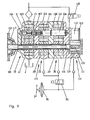
- FIG. 9 is a possible application of a register pump 100 according to the invention with the pumps 10, 20 and 30, further used, wherein the register pump 100 is extended by a flanged to her vacuum pump 110 to a tandem pump.
- the previous pumps 10, 20 and 30 are opposite figure 2 shown rotated by 90 °, so now in this view all conveyor gears 12 and 13, 22 and 23 and 32 and 33 can be seen.
- the valves 16, 26 and 36 of the pumps 10, 20 and 30 are no longer visible.
- the feed gear 12 is fixed on a hollow shaft 101 driven by a gear 102.
- the co-conveying gear 13 driven by the conveying gear 12 is fixed on the bolt 103, which is rotatably supported in the housing 11.
- the bolt 103 has on both sides each an inner polygon 104.
- the co-conveying gears 23 and 33 of the pumps 20 and 30 are fixed to bolts 105 and 106 identical to the bolt 103, respectively.
- About a polygonal piece 107 and a polygonal piece 108 are all bolts 103, 105 and 106 with each other in rotational force connection.
- the so-driven co-conveying gears 23 and 33 drive the meshing with them conveyor gears 22 and 32, which are arranged for assembly reasons on the shaft 101 with play.
- the pump 30 is now different FIG. 2 closed by a housing 111 of the vacuum pump 110, which has a delivery chamber 112 with a lid 113.
- An eccentrically arranged in the delivery chamber 112 rotor 114 drives a wing 115, whereby a gas or air promotion takes place in a known manner.
- the rotor 114 is driven by an inner shaft 116 mounted in the shaft 101.
- the inner shaft 116 can be driven by the gearwheel 102, with a cone clutch 117 arranged in the gearwheel 102 preferably forming the drive of the vacuum pump 110 switchable as required.
- the rotor 114 in the housing 111 is acted upon axially via an electric valve 118 with oil pressure, whereby the rotor 114 axially displaces slightly and via the inner shaft 116, the cone clutch 117 closes. Accordingly, in an axial pressure relief of the rotor 114 caused by the electrovalve 118, the cone clutch 117 is reopened by a lack of axial force and the vacuum pump 110 is switched off.
- FIG. 9 simplified vacuum system for the brake booster 90, which is no longer the in FIG. 1 has memory 96 shown and the solenoid valve 97, is evacuated in normal operation only by the two pumps 20 and 30. Only when there is insufficient negative pressure at the brake booster 90, for example when the internal combustion engine 2 starts or during a prolonged engine idling with the maximum required oil delivery of the three pumps 10, 20 and 30, the vacuum pump 110 is switched on. As a result, on the one hand, maximum operational reliability of the brake booster 90 associated brake system and on the other hand, a minimum drive power of the tandem pump 100 is ensured.
Landscapes
- Engineering & Computer Science (AREA)
- Mechanical Engineering (AREA)
- General Engineering & Computer Science (AREA)
- Lubrication Of Internal Combustion Engines (AREA)
Applications Claiming Priority (2)
| Application Number | Priority Date | Filing Date | Title |
|---|---|---|---|
| DE102011117576 | 2011-11-02 | ||
| DE201210002672 DE102012002672B4 (de) | 2011-11-02 | 2012-02-10 | Registerpumpe |
Publications (1)
| Publication Number | Publication Date |
|---|---|
| EP2589851A2 true EP2589851A2 (fr) | 2013-05-08 |
Family
ID=47225882
Family Applications (1)
| Application Number | Title | Priority Date | Filing Date |
|---|---|---|---|
| EP12007478.6A Withdrawn EP2589851A2 (fr) | 2011-11-02 | 2012-11-02 | Pompe de registre |
Country Status (2)
| Country | Link |
|---|---|
| EP (1) | EP2589851A2 (fr) |
| DE (1) | DE102012002672B4 (fr) |
Cited By (6)
| Publication number | Priority date | Publication date | Assignee | Title |
|---|---|---|---|---|
| GB2522705A (en) * | 2014-02-04 | 2015-08-05 | Jaguar Land Rover Ltd | Oil delivery system and method |
| CN106195233A (zh) * | 2016-08-31 | 2016-12-07 | 苏州亚太金属有限公司 | 分布式混合动力变速器干式油底壳系统 |
| CN111561369A (zh) * | 2019-02-13 | 2020-08-21 | 翰昂系统巴德霍姆堡有限责任公司 | 具有干式油底壳的冷却润滑系统 |
| US11401843B2 (en) | 2019-02-13 | 2022-08-02 | Hanon Systems Bad Homburg GmbH | Cooling lubrication system comprising a dry sump |
| US11867281B2 (en) | 2019-06-18 | 2024-01-09 | Vitesco Technologies GmbH | Pump stage assembly, external gear pump, use of a pump stage assembly and vehicle transmission |
| US12049951B2 (en) | 2019-06-18 | 2024-07-30 | Vitesco Technologies GmbH | Pump stage assembly, external gear pump, use of a pump stage assembly and vehicle transmission |
Families Citing this family (3)
| Publication number | Priority date | Publication date | Assignee | Title |
|---|---|---|---|---|
| DE102013222591B4 (de) | 2013-11-07 | 2018-01-04 | Joma-Polytec Gmbh | Pumpenanordnung mit Unterdruckpumpe und Schmiermittel |
| DE102015005682A1 (de) * | 2015-05-06 | 2016-11-10 | Volkswagen Aktiengesellschaft | Vorrichtung zur Druckregelung einer Ölpumpe |
| DE102022102285A1 (de) | 2022-02-01 | 2023-08-03 | Bayerische Motoren Werke Aktiengesellschaft | Verbrennungskraftmaschine für ein Kraftfahrzeug, insbesondere für einen Kraftwagen, sowie Kraftfahrzeug |
Citations (7)
| Publication number | Priority date | Publication date | Assignee | Title |
|---|---|---|---|---|
| DE19935781A1 (de) | 1998-08-03 | 2000-03-09 | Unisia Jecs Corp | Hydraulikkreisläufe für Verbrennungsmotoren |
| DE10223966A1 (de) | 2002-05-29 | 2003-12-18 | Siemens Ag | Verfahren und Anordnung zur Aktualisierung einer an ein Automatisierungssystem angeschlossenen Bedienstation |
| DE102005015721B3 (de) | 2005-03-31 | 2006-12-21 | Joma-Hydromechanic Gmbh | Vakuumpumpe |
| DE102006029553A1 (de) | 2006-06-26 | 2007-12-27 | Pierburg Gmbh | Ölpumpen- und Vakuumpumpenmodul |
| DE10237801C5 (de) | 2002-01-12 | 2010-02-11 | Voigt, Dieter, Dipl.-Ing. | Vorrichtung zur Druckregelung von Hydraulikpumpen |
| DE10305781B4 (de) | 2003-02-12 | 2010-08-26 | Voigt, Dieter, Dipl.-Ing. | Mehrstufige Schmierölpumpe |
| DE102011008362A1 (de) | 2011-01-12 | 2012-07-12 | Dieter Voigt | Zweistufige Druckregelung |
Family Cites Families (4)
| Publication number | Priority date | Publication date | Assignee | Title |
|---|---|---|---|---|
| DE2833167A1 (de) * | 1978-07-28 | 1980-02-14 | Barmag Barmer Maschf | Baueinheit, bestehend aus einer oelpumpe zur oelumlaufschmierung einer brennkraftmaschine und einer vakuumpumpe zur erzeugung eines vakuums fuer die bremskraftverstaerkung in kraftfahrzeugen |
| DE10223466B4 (de) * | 2001-05-31 | 2015-07-02 | Magna Powertrain Hückeswagen GmbH | Pumpe |
| WO2011095148A2 (fr) * | 2010-02-04 | 2011-08-11 | Ixetic Bad Homburg Gmbh | Pompe tandem |
| DE102010008362A1 (de) | 2010-02-17 | 2011-08-18 | Transcatheter Technologies GmbH, 93053 | Medizinisches Implantat, welches aus einem nicht expandierten Zustand expandierbar ist |
-
2012
- 2012-02-10 DE DE201210002672 patent/DE102012002672B4/de not_active Expired - Fee Related
- 2012-11-02 EP EP12007478.6A patent/EP2589851A2/fr not_active Withdrawn
Patent Citations (7)
| Publication number | Priority date | Publication date | Assignee | Title |
|---|---|---|---|---|
| DE19935781A1 (de) | 1998-08-03 | 2000-03-09 | Unisia Jecs Corp | Hydraulikkreisläufe für Verbrennungsmotoren |
| DE10237801C5 (de) | 2002-01-12 | 2010-02-11 | Voigt, Dieter, Dipl.-Ing. | Vorrichtung zur Druckregelung von Hydraulikpumpen |
| DE10223966A1 (de) | 2002-05-29 | 2003-12-18 | Siemens Ag | Verfahren und Anordnung zur Aktualisierung einer an ein Automatisierungssystem angeschlossenen Bedienstation |
| DE10305781B4 (de) | 2003-02-12 | 2010-08-26 | Voigt, Dieter, Dipl.-Ing. | Mehrstufige Schmierölpumpe |
| DE102005015721B3 (de) | 2005-03-31 | 2006-12-21 | Joma-Hydromechanic Gmbh | Vakuumpumpe |
| DE102006029553A1 (de) | 2006-06-26 | 2007-12-27 | Pierburg Gmbh | Ölpumpen- und Vakuumpumpenmodul |
| DE102011008362A1 (de) | 2011-01-12 | 2012-07-12 | Dieter Voigt | Zweistufige Druckregelung |
Cited By (8)
| Publication number | Priority date | Publication date | Assignee | Title |
|---|---|---|---|---|
| GB2522705A (en) * | 2014-02-04 | 2015-08-05 | Jaguar Land Rover Ltd | Oil delivery system and method |
| GB2522705B (en) * | 2014-02-04 | 2016-06-22 | Jaguar Land Rover Ltd | Oil delivery system and method |
| CN106195233A (zh) * | 2016-08-31 | 2016-12-07 | 苏州亚太金属有限公司 | 分布式混合动力变速器干式油底壳系统 |
| CN111561369A (zh) * | 2019-02-13 | 2020-08-21 | 翰昂系统巴德霍姆堡有限责任公司 | 具有干式油底壳的冷却润滑系统 |
| US11384663B2 (en) | 2019-02-13 | 2022-07-12 | Hanon Systems Bad Homburg GmbH | Cooling lubrication system comprising a dry sump |
| US11401843B2 (en) | 2019-02-13 | 2022-08-02 | Hanon Systems Bad Homburg GmbH | Cooling lubrication system comprising a dry sump |
| US11867281B2 (en) | 2019-06-18 | 2024-01-09 | Vitesco Technologies GmbH | Pump stage assembly, external gear pump, use of a pump stage assembly and vehicle transmission |
| US12049951B2 (en) | 2019-06-18 | 2024-07-30 | Vitesco Technologies GmbH | Pump stage assembly, external gear pump, use of a pump stage assembly and vehicle transmission |
Also Published As
| Publication number | Publication date |
|---|---|
| DE102012002672A1 (de) | 2013-05-02 |
| DE102012002672B4 (de) | 2014-07-24 |
Similar Documents
| Publication | Publication Date | Title |
|---|---|---|
| DE102012002672B4 (de) | Registerpumpe | |
| EP2977647B1 (fr) | Boîte de vitesses d'un véhicule automobile | |
| EP0712997B1 (fr) | Pompe à engrenages internes avec réglage de l'aspiration | |
| EP2440785B1 (fr) | Système de pompage de lubrifiant | |
| DE102009008850B4 (de) | Variable Verdrängergetriebepumpe | |
| EP0724068B1 (fr) | Système d'amenée d'huile | |
| DE102009038777B4 (de) | Rotationspumpe mit variabler Verdrängung | |
| DE102005029086B4 (de) | Ölpumpe für eine Brennkraftmaschine | |
| EP2307726B1 (fr) | Pompe à cylindrée variable | |
| DE102008016499A1 (de) | Hydraulikfluid-Versorgungssystem mit einer Druckverzweigungs-Doppelpumpe für ein Mehrganggetriebe und Verfahren | |
| DE102016204399A1 (de) | Hydrauliksystem für ein Getriebe eines Kraftfahrzeugs | |
| EP1461533B1 (fr) | Pompe | |
| DE2134994B2 (de) | Zweistufige parallel- und außenachsige Rotationskolbenmaschine für elastische Arbeitsmedien | |
| DE7527262U (de) | Rotationsverdichter | |
| WO2008106923A2 (fr) | Système hydraulique | |
| EP2111498A1 (fr) | Pompe à réfrigérant réglable | |
| DE102012202904A1 (de) | Pumpenanordnung zum Erzeugen eines variablen Volumenstromes | |
| DE4209143C1 (fr) | ||
| DE102015115841B4 (de) | Pumpen-Motor-Einheit mit einer Kühlung eines die Pumpe antreibenden Elektromotors mittels Leckagefluid | |
| EP3015708B1 (fr) | Pompes a cellules battantes presentant un comportement de demarrage ameliore | |
| DE102009060188B4 (de) | Verstellventil für die Verstellung des Fördervolumens einer Verdrängerpumpe mit Kaltstartfunktion | |
| DE19523533C2 (de) | Sauggeregelte Innenzahnradpumpe | |
| DE102013108843A1 (de) | Hydrauliksystem | |
| EP2604908A1 (fr) | Système de lubrifiant et éolienne | |
| DE102011008362A1 (de) | Zweistufige Druckregelung |
Legal Events
| Date | Code | Title | Description |
|---|---|---|---|
| PUAI | Public reference made under article 153(3) epc to a published international application that has entered the european phase |
Free format text: ORIGINAL CODE: 0009012 |
|
| AK | Designated contracting states |
Kind code of ref document: A2 Designated state(s): AL AT BE BG CH CY CZ DE DK EE ES FI FR GB GR HR HU IE IS IT LI LT LU LV MC MK MT NL NO PL PT RO RS SE SI SK SM TR |
|
| AX | Request for extension of the european patent |
Extension state: BA ME |
|
| STAA | Information on the status of an ep patent application or granted ep patent |
Free format text: STATUS: THE APPLICATION IS DEEMED TO BE WITHDRAWN |
|
| 18D | Application deemed to be withdrawn |
Effective date: 20150602 |