EP2589873A1 - Chambre de combustion à flux inversé avec une injection d'air de sillage - Google Patents
Chambre de combustion à flux inversé avec une injection d'air de sillage Download PDFInfo
- Publication number
- EP2589873A1 EP2589873A1 EP12190915.4A EP12190915A EP2589873A1 EP 2589873 A1 EP2589873 A1 EP 2589873A1 EP 12190915 A EP12190915 A EP 12190915A EP 2589873 A1 EP2589873 A1 EP 2589873A1
- Authority
- EP
- European Patent Office
- Prior art keywords
- wake
- fluid
- injector
- disposed
- vessel
- Prior art date
- Legal status (The legal status is an assumption and is not a legal conclusion. Google has not performed a legal analysis and makes no representation as to the accuracy of the status listed.)
- Granted
Links
Images

Classifications
-
- F—MECHANICAL ENGINEERING; LIGHTING; HEATING; WEAPONS; BLASTING
- F23—COMBUSTION APPARATUS; COMBUSTION PROCESSES
- F23R—GENERATING COMBUSTION PRODUCTS OF HIGH PRESSURE OR HIGH VELOCITY, e.g. GAS-TURBINE COMBUSTION CHAMBERS
- F23R3/00—Continuous combustion chambers using liquid or gaseous fuel
- F23R3/002—Wall structures
-
- F—MECHANICAL ENGINEERING; LIGHTING; HEATING; WEAPONS; BLASTING
- F23—COMBUSTION APPARATUS; COMBUSTION PROCESSES
- F23R—GENERATING COMBUSTION PRODUCTS OF HIGH PRESSURE OR HIGH VELOCITY, e.g. GAS-TURBINE COMBUSTION CHAMBERS
- F23R3/00—Continuous combustion chambers using liquid or gaseous fuel
- F23R3/42—Continuous combustion chambers using liquid or gaseous fuel characterised by the arrangement or form of the flame tubes or combustion chambers
- F23R3/54—Reverse-flow combustion chambers
-
- F—MECHANICAL ENGINEERING; LIGHTING; HEATING; WEAPONS; BLASTING
- F23—COMBUSTION APPARATUS; COMBUSTION PROCESSES
- F23R—GENERATING COMBUSTION PRODUCTS OF HIGH PRESSURE OR HIGH VELOCITY, e.g. GAS-TURBINE COMBUSTION CHAMBERS
- F23R2900/00—Special features of, or arrangements for continuous combustion chambers; Combustion processes therefor
- F23R2900/03044—Impingement cooled combustion chamber walls or subassemblies
Definitions
- the subject matter disclosed herein relates to a combustor and, more particularly, to a combustor having wake air injection capability.
- air flow is directed towards premixers in which fuel and air are mixed prior to being combusted in a combustion zone of a combustor.
- the fuel may be provided by way of fuel injectors disposed in the air flow whereby the mixing of the fuel and air is achieved at least partly as a result of cross flow velocities of the air flow being maintained at and around the fuel injectors.
- wakes can be generated by any streamlined or non-streamlined bodies disposed within the air flow. These wakes can disturb the air flow and lead to decreased cross flow velocities at and around the fuel injectors. The decreased cross flow velocities can negatively affect flame holding capability of the system. In some cases, fuel can be pulled up into recirculation zones in the combustion zone where mixed fuel can thus come in contact with hot surfaces of the combustor causing them to autoignite and initiate flame holding in flow sleeve liner annulus passages.
- a combustor having wake air injection includes a fuel nozzle, first and second vessels formed and disposed to define a flow path along which a first fluid flows in first and second opposite directions toward the fuel nozzle, a vane disposed in the flow path and an injector to inject a second fluid into wake formed by an obstruction disposed in the flow path upstream from the vane.
- a combustor having wake air injection includes a fuel nozzle configured to form a mixture of combustible materials to be supplied for combustion operations, first and second vessels formed and disposed about the fuel nozzle to define a flow path along which a first fluid flows in a first axial direction, then a radial direction and then a second axial direction, which is opposite the first axial direction, toward the fuel nozzle, a vane disposed in the flow path and an injector to inject a second fluid into wake formed by an obstruction disposed in the flow path at an axial location upstream from the vane.
- a wake air injection apparatus includes a first vessel having an end in which a mixture of combustible materials is formed and defining a combustion zone in which the mixture is combusted, a second vessel disposed about the first vessel to define a first space through which a flow of a first fluid is directed toward the end of the first vessel and in which an obstruction is disposed to form a wake in the flow of the first fluid and a third vessel disposed about the second vessel to define a second space to receive a second fluid.
- the second vessel defines an injector, by which the second fluid is injected from the second space to the first space, and which is positioned downstream from the obstruction relative to the flow of the first fluid and in substantial, circumferential alignment with the wake.
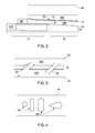
- a wake air injection apparatus (“the apparatus") 10 is provided for use with a combustor 20 of, for example, a gas turbine engine or another type of turbomachine.
- the apparatus 10 includes a first vessel 30, a second vessel 40, a third vessel 50 and an injector 60.
- the first vessel 30 may be provided as a liner of the combustor 20 and has an end 31 that may be formed and disposed about a fuel nozzle 201 in which a mixture of combustible materials is formed such that the mixture may be supplied for combustion operations.
- the first vessel 30 is further formed to define a combustion zone 32 therein in which the mixture of the combustible materials is combusted.
- the combustion zone 32 is aft of the end 31, which is proximate to a head end of the combustor 20.
- the second vessel 40 is disposed about the first vessel 30 and may be provided as a flow sleeve of the combustor 20.
- the second vessel 40 being disposed about the first vessel 30, may be formed to define a first space 400 in the annulus between the first vessel 30 and the second vessel 40 through which a flow of a first fluid, such as relatively low pressure impingement air, is directed toward the end 31 of the first vessel 30.
- a first fluid such as relatively low pressure impingement air
- the first space 400 forms a flow path along which the first fluid flows in a reverse flow pattern including a first axial direction at a radial location defined radially outwardly of the fuel nozzle 201, an inward radial direction axially forward of the fuel nozzle 201 and a second axial direction, which is opposite the first axial direction, at a radial location defined to be substantially radially aligned with the fuel nozzle 201.
- the third vessel 50 may be disposed about the second vessel 40 and may be provided as a compressor discharge casing (CDC).
- the third vessel 50 being disposed about the second vessel 40, may be formed to define a second space 500 in the annulus between the second vessel 40 and the third vessel 50.
- a second fluid such as relatively high pressure CDC air may be supplied to the second space 500.
- At least one or more obstructions 70 and at least one or more vanes 80 may be disposed in the first space 400.
- the at least one or more vanes 80 may be provided, for example, as part of a quaternary fuel injection system and are disposed in a forward section of the first space 400. That is, each vane 80 may serve as a fuel injector by which fuel is injected into the flow of the first fluid.
- the at least one or more obstructions 70 may or may not be streamlined and are each disposed in the first space 400 at axial locations aft of the at least one or more vanes 80. In accordance with embodiments, as shown in FIG.
- the obstruction 70 may be substantially, axially aligned with a section of the combustion zone 32, which is proximate to the end 31 of the first vessel 30.
- the first fluid encounters the at least one or more obstructions 70 prior to encountering the at least one or more vanes 80.
- each obstruction 70 may form a wake in the flow of the first fluid and, since each obstruction 70 may be substantially circumferentially aligned with a corresponding one or more vanes 80, the wake may encompass the corresponding one or more vanes 80. This can lead to insufficient cross flow velocities at or around the vanes 80 and to decreased flame holding capability.
- the second vessel 40 is formed to define the injector 60 by which the second fluid is injected from the second space 500 to the first space 400 with an angle of injection of between about 20-80° relative to a centerline of the combustor or the exemplary gas turbine engine in accordance with embodiments.
- the injector 60 is positioned downstream from the obstruction 70 relative to the flow of the first fluid through the first space 400 or, in other words, at an axial location that is defined axially forward of the obstruction 70.
- the injector 60 is further positioned in substantial, circumferential alignment with the wake formed by the obstruction 70.
- the injection of the second fluid from the second space 500 may serve to reduce disturbances associated with the wake and thereby achieve necessary cross flow velocities at the corresponding one or more vanes 80 for acceptable flame holding margin.
- the injector 60 may alternatively extend along radial and axial dimensions relative to the combustion zone 32, as shown in FIG. 3 .
- the injector 60 may have a slot-shaped cross-section, an elliptical or circular cross-section, a race track-shaped cross-section (i.e., a rectangular cross-section with rounded corners or longitudinal ends) or a teardrop-shaped cross-section.
- the injector 60 may be defined as a plurality of injectors 60.
- One or more of the plural injectors 60 may have a unique shape.
- one or more of the plural injectors 60 may have a unique penetration depth into the first space 400.
Landscapes
- Engineering & Computer Science (AREA)
- Chemical & Material Sciences (AREA)
- Combustion & Propulsion (AREA)
- Mechanical Engineering (AREA)
- General Engineering & Computer Science (AREA)
- Pre-Mixing And Non-Premixing Gas Burner (AREA)
- Spray-Type Burners (AREA)
Applications Claiming Priority (1)
| Application Number | Priority Date | Filing Date | Title |
|---|---|---|---|
| US13/289,567 US8899975B2 (en) | 2011-11-04 | 2011-11-04 | Combustor having wake air injection |
Publications (2)
| Publication Number | Publication Date |
|---|---|
| EP2589873A1 true EP2589873A1 (fr) | 2013-05-08 |
| EP2589873B1 EP2589873B1 (fr) | 2017-06-28 |
Family
ID=47143657
Family Applications (1)
| Application Number | Title | Priority Date | Filing Date |
|---|---|---|---|
| EP12190915.4A Active EP2589873B1 (fr) | 2011-11-04 | 2012-10-31 | Chambre de combustion à flux inversé avec une injection d'air de sillage |
Country Status (3)
| Country | Link |
|---|---|
| US (1) | US8899975B2 (fr) |
| EP (1) | EP2589873B1 (fr) |
| CN (1) | CN103090413B (fr) |
Families Citing this family (11)
| Publication number | Priority date | Publication date | Assignee | Title |
|---|---|---|---|---|
| US8899975B2 (en) | 2011-11-04 | 2014-12-02 | General Electric Company | Combustor having wake air injection |
| US9267687B2 (en) | 2011-11-04 | 2016-02-23 | General Electric Company | Combustion system having a venturi for reducing wakes in an airflow |
| US9322553B2 (en) | 2013-05-08 | 2016-04-26 | General Electric Company | Wake manipulating structure for a turbine system |
| US9739201B2 (en) | 2013-05-08 | 2017-08-22 | General Electric Company | Wake reducing structure for a turbine system and method of reducing wake |
| US9435221B2 (en) | 2013-08-09 | 2016-09-06 | General Electric Company | Turbomachine airfoil positioning |
| EP2865850B1 (fr) * | 2013-10-24 | 2018-01-03 | Ansaldo Energia Switzerland AG | Agencement de refroidissement par impact |
| US9494321B2 (en) * | 2013-12-10 | 2016-11-15 | General Electric Company | Wake reducing structure for a turbine system |
| US10344978B2 (en) | 2016-03-15 | 2019-07-09 | General Electric Company | Combustion liner cooling |
| US10823126B2 (en) | 2018-08-31 | 2020-11-03 | General Electric Company | Combustion-powered flow control actuator with external fuel injector |
| CN111810316A (zh) * | 2020-07-01 | 2020-10-23 | 中国空气动力研究与发展中心 | 一种超燃冲压发动机的燃料喷孔结构 |
| US11629857B2 (en) | 2021-03-31 | 2023-04-18 | General Electric Company | Combustor having a wake energizer |
Citations (3)
| Publication number | Priority date | Publication date | Assignee | Title |
|---|---|---|---|---|
| EP1130321A1 (fr) * | 2000-02-25 | 2001-09-05 | General Electric Company | Collerettes de refroidissement pour chemise de chambre de combustion et procédé correspondant |
| EP2154431A2 (fr) * | 2008-08-14 | 2010-02-17 | Alstom Technology Ltd | Machine thermique |
| DE102010060286A1 (de) * | 2009-11-11 | 2011-05-12 | General Electric Co. | Brennkammereinrichtung für eine Gasturbine, mit verbesserter Kühlung |
Family Cites Families (59)
| Publication number | Priority date | Publication date | Assignee | Title |
|---|---|---|---|---|
| US3734639A (en) | 1968-01-25 | 1973-05-22 | Gen Motors Corp | Turbine cooling |
| SE343106B (fr) | 1969-06-30 | 1972-02-28 | E Janelid | |
| JPS54114619A (en) | 1978-02-28 | 1979-09-06 | Toshiba Corp | Natural frequency adjusting method of turbine blade |
| US4259842A (en) * | 1978-12-11 | 1981-04-07 | General Electric Company | Combustor liner slot with cooled props |
| CA1324999C (fr) | 1986-04-30 | 1993-12-07 | Walter M. Presz, Jr. | Elements a surfaces offrant une faible resistance au frottement |
| GB2192229B (en) | 1986-07-04 | 1990-05-02 | Rolls Royce Plc | A compressor and air bleed system |
| CH672004A5 (fr) | 1986-09-26 | 1989-10-13 | Bbc Brown Boveri & Cie | |
| US4896510A (en) * | 1987-02-06 | 1990-01-30 | General Electric Company | Combustor liner cooling arrangement |
| US5274991A (en) | 1992-03-30 | 1994-01-04 | General Electric Company | Dry low NOx multi-nozzle combustion liner cap assembly |
| US5406786A (en) | 1993-07-16 | 1995-04-18 | Air Products And Chemicals, Inc. | Integrated air separation - gas turbine electrical generation process |
| US5486091A (en) | 1994-04-19 | 1996-01-23 | United Technologies Corporation | Gas turbine airfoil clocking |
| US6170264B1 (en) | 1997-09-22 | 2001-01-09 | Clean Energy Systems, Inc. | Hydrocarbon combustion power generation system with CO2 sequestration |
| GB2311596B (en) | 1996-03-29 | 2000-07-12 | Europ Gas Turbines Ltd | Combustor for gas - or liquid - fuelled turbine |
| US5813828A (en) | 1997-03-18 | 1998-09-29 | Norris; Thomas R. | Method and apparatus for enhancing gas turbo machinery flow |
| KR100550689B1 (ko) | 1998-02-10 | 2006-02-08 | 제너럴 일렉트릭 캄파니 | 가스 터빈의 연소 시스템용 버너 및 연료와 공기의 예비혼합 방법 |
| FR2775288B1 (fr) | 1998-02-26 | 2000-03-31 | Rhone Poulenc Rorer Sa | Derives de streptogramines, leur preparation et les compositons qui les contiennent |
| US6626635B1 (en) | 1998-09-30 | 2003-09-30 | General Electric Company | System for controlling clearance between blade tips and a surrounding casing in rotating machinery |
| US6174129B1 (en) | 1999-01-07 | 2001-01-16 | Siemens Westinghouse Power Corporation | Turbine vane clocking mechanism and method of assembling a turbine having such a mechanism |
| US6345493B1 (en) | 1999-06-04 | 2002-02-12 | Air Products And Chemicals, Inc. | Air separation process and system with gas turbine drivers |
| GB2359882B (en) * | 2000-02-29 | 2004-01-07 | Rolls Royce Plc | Wall elements for gas turbine engine combustors |
| US6389793B1 (en) | 2000-04-19 | 2002-05-21 | General Electric Company | Combustion turbine cooling media supply system and related method |
| US6622470B2 (en) | 2000-05-12 | 2003-09-23 | Clean Energy Systems, Inc. | Semi-closed brayton cycle gas turbine power systems |
| US6435814B1 (en) | 2000-05-16 | 2002-08-20 | General Electric Company | Film cooling air pocket in a closed loop cooled airfoil |
| US6602458B1 (en) | 2000-06-28 | 2003-08-05 | Rubbermaid Incorporated | Reduced flash molding |
| US6402458B1 (en) | 2000-08-16 | 2002-06-11 | General Electric Company | Clock turbine airfoil cooling |
| US6442941B1 (en) | 2000-09-11 | 2002-09-03 | General Electric Company | Compressor discharge bleed air circuit in gas turbine plants and related method |
| IT1320722B1 (it) | 2000-10-23 | 2003-12-10 | Fiatavio Spa | Metodo per il posizionamento di schiere di stadi di una turbina,particolarmente per motori aeronautici. |
| US6409126B1 (en) | 2000-11-01 | 2002-06-25 | Lockhead Martin Corporation | Passive flow control of bluff body wake turbulence |
| GB2373319B (en) | 2001-03-12 | 2005-03-30 | Rolls Royce Plc | Combustion apparatus |
| US6554562B2 (en) | 2001-06-15 | 2003-04-29 | Honeywell International, Inc. | Combustor hot streak alignment for gas turbine engine |
| USD511377S1 (en) | 2002-07-01 | 2005-11-08 | Donaldson Company, Inc. | Inlet air filter hood module for gas turbine systems |
| US6899081B2 (en) | 2002-09-20 | 2005-05-31 | Visteon Global Technologies, Inc. | Flow conditioning device |
| US6926345B2 (en) | 2002-09-20 | 2005-08-09 | The Regents Of The University Of California | Apparatus and method for reducing drag of a bluff body in ground effect using counter-rotating vortex pairs |
| US20040109756A1 (en) | 2002-12-09 | 2004-06-10 | Mitsubishi Heavy Industries Ltd. | Gas turbine |
| US6935116B2 (en) | 2003-04-28 | 2005-08-30 | Power Systems Mfg., Llc | Flamesheet combustor |
| US6866479B2 (en) | 2003-05-16 | 2005-03-15 | Mitsubishi Heavy Industries, Ltd. | Exhaust diffuser for axial-flow turbine |
| EP1482246A1 (fr) | 2003-05-30 | 2004-12-01 | Siemens Aktiengesellschaft | Chambre de combustion |
| US7007478B2 (en) | 2004-06-30 | 2006-03-07 | General Electric Company | Multi-venturi tube fuel injector for a gas turbine combustor |
| US7340129B2 (en) | 2004-08-04 | 2008-03-04 | Colorado State University Research Foundation | Fiber laser coupled optical spark delivery system |
| US7412129B2 (en) | 2004-08-04 | 2008-08-12 | Colorado State University Research Foundation | Fiber coupled optical spark delivery system |
| US7574865B2 (en) | 2004-11-18 | 2009-08-18 | Siemens Energy, Inc. | Combustor flow sleeve with optimized cooling and airflow distribution |
| US7707835B2 (en) | 2005-06-15 | 2010-05-04 | General Electric Company | Axial flow sleeve for a turbine combustor and methods of introducing flow sleeve air |
| US7762074B2 (en) | 2006-04-04 | 2010-07-27 | Siemens Energy, Inc. | Air flow conditioner for a combustor can of a gas turbine engine |
| US7654320B2 (en) | 2006-04-07 | 2010-02-02 | Occidental Energy Ventures Corp. | System and method for processing a mixture of hydrocarbon and CO2 gas produced from a hydrocarbon reservoir |
| US8117845B2 (en) | 2007-04-27 | 2012-02-21 | General Electric Company | Systems to facilitate reducing flashback/flame holding in combustion systems |
| US7966820B2 (en) | 2007-08-15 | 2011-06-28 | General Electric Company | Method and apparatus for combusting fuel within a gas turbine engine |
| FR2925106B1 (fr) | 2007-12-14 | 2010-01-22 | Snecma | Procede de conception d'une turbine multi-etages de turbomachine |
| US7896645B2 (en) * | 2008-05-30 | 2011-03-01 | Universal Cleanair Technologies | Three phased combustion system |
| US20100054929A1 (en) | 2008-09-04 | 2010-03-04 | General Electric Company | Turbine airfoil clocking |
| US8307657B2 (en) * | 2009-03-10 | 2012-11-13 | General Electric Company | Combustor liner cooling system |
| US8234872B2 (en) | 2009-05-01 | 2012-08-07 | General Electric Company | Turbine air flow conditioner |
| US8650881B2 (en) | 2009-06-30 | 2014-02-18 | General Electric Company | Methods and apparatus for combustor fuel circuit for ultra low calorific fuels |
| US8381526B2 (en) | 2010-02-15 | 2013-02-26 | General Electric Company | Systems and methods of providing high pressure air to a head end of a combustor |
| US8707672B2 (en) | 2010-09-10 | 2014-04-29 | General Electric Company | Apparatus and method for cooling a combustor cap |
| US8991187B2 (en) | 2010-10-11 | 2015-03-31 | General Electric Company | Combustor with a lean pre-nozzle fuel injection system |
| US8991188B2 (en) | 2011-01-05 | 2015-03-31 | General Electric Company | Fuel nozzle passive purge cap flow |
| US8893501B2 (en) | 2011-03-28 | 2014-11-25 | General Eletric Company | Combustor crossfire tube |
| US8919127B2 (en) | 2011-05-24 | 2014-12-30 | General Electric Company | System and method for flow control in gas turbine engine |
| US8899975B2 (en) | 2011-11-04 | 2014-12-02 | General Electric Company | Combustor having wake air injection |
-
2011
- 2011-11-04 US US13/289,567 patent/US8899975B2/en active Active
-
2012
- 2012-10-31 EP EP12190915.4A patent/EP2589873B1/fr active Active
- 2012-11-02 CN CN201210433805.6A patent/CN103090413B/zh active Active
Patent Citations (3)
| Publication number | Priority date | Publication date | Assignee | Title |
|---|---|---|---|---|
| EP1130321A1 (fr) * | 2000-02-25 | 2001-09-05 | General Electric Company | Collerettes de refroidissement pour chemise de chambre de combustion et procédé correspondant |
| EP2154431A2 (fr) * | 2008-08-14 | 2010-02-17 | Alstom Technology Ltd | Machine thermique |
| DE102010060286A1 (de) * | 2009-11-11 | 2011-05-12 | General Electric Co. | Brennkammereinrichtung für eine Gasturbine, mit verbesserter Kühlung |
Also Published As
| Publication number | Publication date |
|---|---|
| CN103090413A (zh) | 2013-05-08 |
| US8899975B2 (en) | 2014-12-02 |
| US20130115566A1 (en) | 2013-05-09 |
| EP2589873B1 (fr) | 2017-06-28 |
| CN103090413B (zh) | 2017-04-12 |
Similar Documents
| Publication | Publication Date | Title |
|---|---|---|
| US8899975B2 (en) | Combustor having wake air injection | |
| US8418468B2 (en) | Segmented annular ring-manifold quaternary fuel distributor | |
| US8438852B2 (en) | Annular ring-manifold quaternary fuel distributor | |
| US9038395B2 (en) | Combustors with quench inserts | |
| US9062884B2 (en) | Combustors with quench inserts | |
| JP6335903B2 (ja) | 火炎シート燃焼器ドーム | |
| US8904796B2 (en) | Flashback resistant tubes for late lean injector and method for forming the tubes | |
| US20100064691A1 (en) | Flashback resistant pre-mixer assembly | |
| EP1826485B1 (fr) | Brûleur et procédé de combustion avec le brûleur | |
| EP4317785B1 (fr) | Injecteur à deux carburants | |
| JP2010065963A (ja) | 燃焼器,燃焼器の燃料供給方法及び燃焼器の改造方法 | |
| US20120036859A1 (en) | Combustor transition piece with dilution sleeves and related method | |
| EP4206534B1 (fr) | Prémélangeur de carburant de turbine à gaz | |
| JP2014122784A (ja) | 燃焼器に燃料を供給するためのシステム | |
| CN102809175A (zh) | 喷射器设备 | |
| US20180340689A1 (en) | Low Profile Axially Staged Fuel Injector | |
| EP2554909A2 (fr) | Injecteur de carburant | |
| JP7071028B2 (ja) | 燃焼器ライナの冷却 | |
| US20140366541A1 (en) | Systems and apparatus relating to fuel injection in gas turbines | |
| US20150276225A1 (en) | Combustor wth pre-mixing fuel nozzle assembly | |
| EP3586062B1 (fr) | Système de combustion à injection de carburant axialement étagé | |
| EP3220048B1 (fr) | Refroidissement d'une chemise de combustion |
Legal Events
| Date | Code | Title | Description |
|---|---|---|---|
| PUAI | Public reference made under article 153(3) epc to a published international application that has entered the european phase |
Free format text: ORIGINAL CODE: 0009012 |
|
| AK | Designated contracting states |
Kind code of ref document: A1 Designated state(s): AL AT BE BG CH CY CZ DE DK EE ES FI FR GB GR HR HU IE IS IT LI LT LU LV MC MK MT NL NO PL PT RO RS SE SI SK SM TR |
|
| AX | Request for extension of the european patent |
Extension state: BA ME |
|
| 17P | Request for examination filed |
Effective date: 20131108 |
|
| RBV | Designated contracting states (corrected) |
Designated state(s): AL AT BE BG CH CY CZ DE DK EE ES FI FR GB GR HR HU IE IS IT LI LT LU LV MC MK MT NL NO PL PT RO RS SE SI SK SM TR |
|
| 17Q | First examination report despatched |
Effective date: 20160314 |
|
| GRAP | Despatch of communication of intention to grant a patent |
Free format text: ORIGINAL CODE: EPIDOSNIGR1 |
|
| INTG | Intention to grant announced |
Effective date: 20170307 |
|
| GRAS | Grant fee paid |
Free format text: ORIGINAL CODE: EPIDOSNIGR3 |
|
| GRAA | (expected) grant |
Free format text: ORIGINAL CODE: 0009210 |
|
| AK | Designated contracting states |
Kind code of ref document: B1 Designated state(s): AL AT BE BG CH CY CZ DE DK EE ES FI FR GB GR HR HU IE IS IT LI LT LU LV MC MK MT NL NO PL PT RO RS SE SI SK SM TR |
|
| REG | Reference to a national code |
Ref country code: GB Ref legal event code: FG4D |
|
| REG | Reference to a national code |
Ref country code: CH Ref legal event code: EP |
|
| REG | Reference to a national code |
Ref country code: AT Ref legal event code: REF Ref document number: 905213 Country of ref document: AT Kind code of ref document: T Effective date: 20170715 |
|
| REG | Reference to a national code |
Ref country code: IE Ref legal event code: FG4D |
|
| REG | Reference to a national code |
Ref country code: DE Ref legal event code: R096 Ref document number: 602012033913 Country of ref document: DE |
|
| PG25 | Lapsed in a contracting state [announced via postgrant information from national office to epo] |
Ref country code: NO Free format text: LAPSE BECAUSE OF FAILURE TO SUBMIT A TRANSLATION OF THE DESCRIPTION OR TO PAY THE FEE WITHIN THE PRESCRIBED TIME-LIMIT Effective date: 20170928 Ref country code: HR Free format text: LAPSE BECAUSE OF FAILURE TO SUBMIT A TRANSLATION OF THE DESCRIPTION OR TO PAY THE FEE WITHIN THE PRESCRIBED TIME-LIMIT Effective date: 20170628 Ref country code: FI Free format text: LAPSE BECAUSE OF FAILURE TO SUBMIT A TRANSLATION OF THE DESCRIPTION OR TO PAY THE FEE WITHIN THE PRESCRIBED TIME-LIMIT Effective date: 20170628 Ref country code: LT Free format text: LAPSE BECAUSE OF FAILURE TO SUBMIT A TRANSLATION OF THE DESCRIPTION OR TO PAY THE FEE WITHIN THE PRESCRIBED TIME-LIMIT Effective date: 20170628 Ref country code: GR Free format text: LAPSE BECAUSE OF FAILURE TO SUBMIT A TRANSLATION OF THE DESCRIPTION OR TO PAY THE FEE WITHIN THE PRESCRIBED TIME-LIMIT Effective date: 20170929 |
|
| REG | Reference to a national code |
Ref country code: NL Ref legal event code: MP Effective date: 20170628 |
|
| REG | Reference to a national code |
Ref country code: LT Ref legal event code: MG4D |
|
| REG | Reference to a national code |
Ref country code: AT Ref legal event code: MK05 Ref document number: 905213 Country of ref document: AT Kind code of ref document: T Effective date: 20170628 |
|
| PG25 | Lapsed in a contracting state [announced via postgrant information from national office to epo] |
Ref country code: BG Free format text: LAPSE BECAUSE OF FAILURE TO SUBMIT A TRANSLATION OF THE DESCRIPTION OR TO PAY THE FEE WITHIN THE PRESCRIBED TIME-LIMIT Effective date: 20170928 Ref country code: RS Free format text: LAPSE BECAUSE OF FAILURE TO SUBMIT A TRANSLATION OF THE DESCRIPTION OR TO PAY THE FEE WITHIN THE PRESCRIBED TIME-LIMIT Effective date: 20170628 Ref country code: SE Free format text: LAPSE BECAUSE OF FAILURE TO SUBMIT A TRANSLATION OF THE DESCRIPTION OR TO PAY THE FEE WITHIN THE PRESCRIBED TIME-LIMIT Effective date: 20170628 Ref country code: NL Free format text: LAPSE BECAUSE OF FAILURE TO SUBMIT A TRANSLATION OF THE DESCRIPTION OR TO PAY THE FEE WITHIN THE PRESCRIBED TIME-LIMIT Effective date: 20170628 Ref country code: LV Free format text: LAPSE BECAUSE OF FAILURE TO SUBMIT A TRANSLATION OF THE DESCRIPTION OR TO PAY THE FEE WITHIN THE PRESCRIBED TIME-LIMIT Effective date: 20170628 |
|
| PG25 | Lapsed in a contracting state [announced via postgrant information from national office to epo] |
Ref country code: AT Free format text: LAPSE BECAUSE OF FAILURE TO SUBMIT A TRANSLATION OF THE DESCRIPTION OR TO PAY THE FEE WITHIN THE PRESCRIBED TIME-LIMIT Effective date: 20170628 Ref country code: RO Free format text: LAPSE BECAUSE OF FAILURE TO SUBMIT A TRANSLATION OF THE DESCRIPTION OR TO PAY THE FEE WITHIN THE PRESCRIBED TIME-LIMIT Effective date: 20170628 Ref country code: CZ Free format text: LAPSE BECAUSE OF FAILURE TO SUBMIT A TRANSLATION OF THE DESCRIPTION OR TO PAY THE FEE WITHIN THE PRESCRIBED TIME-LIMIT Effective date: 20170628 Ref country code: EE Free format text: LAPSE BECAUSE OF FAILURE TO SUBMIT A TRANSLATION OF THE DESCRIPTION OR TO PAY THE FEE WITHIN THE PRESCRIBED TIME-LIMIT Effective date: 20170628 Ref country code: SK Free format text: LAPSE BECAUSE OF FAILURE TO SUBMIT A TRANSLATION OF THE DESCRIPTION OR TO PAY THE FEE WITHIN THE PRESCRIBED TIME-LIMIT Effective date: 20170628 |
|
| PG25 | Lapsed in a contracting state [announced via postgrant information from national office to epo] |
Ref country code: SM Free format text: LAPSE BECAUSE OF FAILURE TO SUBMIT A TRANSLATION OF THE DESCRIPTION OR TO PAY THE FEE WITHIN THE PRESCRIBED TIME-LIMIT Effective date: 20170628 Ref country code: ES Free format text: LAPSE BECAUSE OF FAILURE TO SUBMIT A TRANSLATION OF THE DESCRIPTION OR TO PAY THE FEE WITHIN THE PRESCRIBED TIME-LIMIT Effective date: 20170628 Ref country code: PL Free format text: LAPSE BECAUSE OF FAILURE TO SUBMIT A TRANSLATION OF THE DESCRIPTION OR TO PAY THE FEE WITHIN THE PRESCRIBED TIME-LIMIT Effective date: 20170628 Ref country code: IS Free format text: LAPSE BECAUSE OF FAILURE TO SUBMIT A TRANSLATION OF THE DESCRIPTION OR TO PAY THE FEE WITHIN THE PRESCRIBED TIME-LIMIT Effective date: 20171028 |
|
| REG | Reference to a national code |
Ref country code: DE Ref legal event code: R097 Ref document number: 602012033913 Country of ref document: DE |
|
| PG25 | Lapsed in a contracting state [announced via postgrant information from national office to epo] |
Ref country code: DK Free format text: LAPSE BECAUSE OF FAILURE TO SUBMIT A TRANSLATION OF THE DESCRIPTION OR TO PAY THE FEE WITHIN THE PRESCRIBED TIME-LIMIT Effective date: 20170628 |
|
| PLBE | No opposition filed within time limit |
Free format text: ORIGINAL CODE: 0009261 |
|
| STAA | Information on the status of an ep patent application or granted ep patent |
Free format text: STATUS: NO OPPOSITION FILED WITHIN TIME LIMIT |
|
| PG25 | Lapsed in a contracting state [announced via postgrant information from national office to epo] |
Ref country code: MC Free format text: LAPSE BECAUSE OF FAILURE TO SUBMIT A TRANSLATION OF THE DESCRIPTION OR TO PAY THE FEE WITHIN THE PRESCRIBED TIME-LIMIT Effective date: 20170628 |
|
| REG | Reference to a national code |
Ref country code: CH Ref legal event code: PL |
|
| 26N | No opposition filed |
Effective date: 20180329 |
|
| GBPC | Gb: european patent ceased through non-payment of renewal fee |
Effective date: 20171031 |
|
| REG | Reference to a national code |
Ref country code: IE Ref legal event code: MM4A |
|
| REG | Reference to a national code |
Ref country code: FR Ref legal event code: ST Effective date: 20180629 |
|
| PG25 | Lapsed in a contracting state [announced via postgrant information from national office to epo] |
Ref country code: GB Free format text: LAPSE BECAUSE OF NON-PAYMENT OF DUE FEES Effective date: 20171031 Ref country code: CH Free format text: LAPSE BECAUSE OF NON-PAYMENT OF DUE FEES Effective date: 20171031 Ref country code: LI Free format text: LAPSE BECAUSE OF NON-PAYMENT OF DUE FEES Effective date: 20171031 Ref country code: LU Free format text: LAPSE BECAUSE OF NON-PAYMENT OF DUE FEES Effective date: 20171031 |
|
| REG | Reference to a national code |
Ref country code: BE Ref legal event code: MM Effective date: 20171031 |
|
| PG25 | Lapsed in a contracting state [announced via postgrant information from national office to epo] |
Ref country code: BE Free format text: LAPSE BECAUSE OF NON-PAYMENT OF DUE FEES Effective date: 20171031 Ref country code: SI Free format text: LAPSE BECAUSE OF FAILURE TO SUBMIT A TRANSLATION OF THE DESCRIPTION OR TO PAY THE FEE WITHIN THE PRESCRIBED TIME-LIMIT Effective date: 20170628 Ref country code: FR Free format text: LAPSE BECAUSE OF NON-PAYMENT OF DUE FEES Effective date: 20171031 |
|
| PG25 | Lapsed in a contracting state [announced via postgrant information from national office to epo] |
Ref country code: MT Free format text: LAPSE BECAUSE OF NON-PAYMENT OF DUE FEES Effective date: 20171031 |
|
| PG25 | Lapsed in a contracting state [announced via postgrant information from national office to epo] |
Ref country code: IE Free format text: LAPSE BECAUSE OF NON-PAYMENT OF DUE FEES Effective date: 20171031 |
|
| PG25 | Lapsed in a contracting state [announced via postgrant information from national office to epo] |
Ref country code: HU Free format text: LAPSE BECAUSE OF FAILURE TO SUBMIT A TRANSLATION OF THE DESCRIPTION OR TO PAY THE FEE WITHIN THE PRESCRIBED TIME-LIMIT; INVALID AB INITIO Effective date: 20121031 |
|
| PG25 | Lapsed in a contracting state [announced via postgrant information from national office to epo] |
Ref country code: CY Free format text: LAPSE BECAUSE OF NON-PAYMENT OF DUE FEES Effective date: 20170628 |
|
| PG25 | Lapsed in a contracting state [announced via postgrant information from national office to epo] |
Ref country code: MK Free format text: LAPSE BECAUSE OF FAILURE TO SUBMIT A TRANSLATION OF THE DESCRIPTION OR TO PAY THE FEE WITHIN THE PRESCRIBED TIME-LIMIT Effective date: 20170628 |
|
| PG25 | Lapsed in a contracting state [announced via postgrant information from national office to epo] |
Ref country code: TR Free format text: LAPSE BECAUSE OF FAILURE TO SUBMIT A TRANSLATION OF THE DESCRIPTION OR TO PAY THE FEE WITHIN THE PRESCRIBED TIME-LIMIT Effective date: 20170628 |
|
| PG25 | Lapsed in a contracting state [announced via postgrant information from national office to epo] |
Ref country code: PT Free format text: LAPSE BECAUSE OF FAILURE TO SUBMIT A TRANSLATION OF THE DESCRIPTION OR TO PAY THE FEE WITHIN THE PRESCRIBED TIME-LIMIT Effective date: 20170628 |
|
| PG25 | Lapsed in a contracting state [announced via postgrant information from national office to epo] |
Ref country code: AL Free format text: LAPSE BECAUSE OF FAILURE TO SUBMIT A TRANSLATION OF THE DESCRIPTION OR TO PAY THE FEE WITHIN THE PRESCRIBED TIME-LIMIT Effective date: 20170628 |
|
| REG | Reference to a national code |
Ref country code: DE Ref legal event code: R081 Ref document number: 602012033913 Country of ref document: DE Owner name: GENERAL ELECTRIC TECHNOLOGY GMBH, CH Free format text: FORMER OWNER: GENERAL ELECTRIC COMPANY, SCHENECTADY, N.Y., US |
|
| PGFP | Annual fee paid to national office [announced via postgrant information from national office to epo] |
Ref country code: IT Payment date: 20250923 Year of fee payment: 14 |
|
| PGFP | Annual fee paid to national office [announced via postgrant information from national office to epo] |
Ref country code: DE Payment date: 20250923 Year of fee payment: 14 |