EP2154431A2 - Machine thermique - Google Patents
Machine thermique Download PDFInfo
- Publication number
- EP2154431A2 EP2154431A2 EP09167590A EP09167590A EP2154431A2 EP 2154431 A2 EP2154431 A2 EP 2154431A2 EP 09167590 A EP09167590 A EP 09167590A EP 09167590 A EP09167590 A EP 09167590A EP 2154431 A2 EP2154431 A2 EP 2154431A2
- Authority
- EP
- European Patent Office
- Prior art keywords
- cooling
- shells
- parting plane
- kühlhemdsegmente
- thermal machine
- Prior art date
- Legal status (The legal status is an assumption and is not a legal conclusion. Google has not performed a legal analysis and makes no representation as to the accuracy of the status listed.)
- Granted
Links
Images


Classifications
-
- F—MECHANICAL ENGINEERING; LIGHTING; HEATING; WEAPONS; BLASTING
- F23—COMBUSTION APPARATUS; COMBUSTION PROCESSES
- F23R—GENERATING COMBUSTION PRODUCTS OF HIGH PRESSURE OR HIGH VELOCITY, e.g. GAS-TURBINE COMBUSTION CHAMBERS
- F23R3/00—Continuous combustion chambers using liquid or gaseous fuel
- F23R3/42—Continuous combustion chambers using liquid or gaseous fuel characterised by the arrangement or form of the flame tubes or combustion chambers
- F23R3/54—Reverse-flow combustion chambers
-
- F—MECHANICAL ENGINEERING; LIGHTING; HEATING; WEAPONS; BLASTING
- F23—COMBUSTION APPARATUS; COMBUSTION PROCESSES
- F23R—GENERATING COMBUSTION PRODUCTS OF HIGH PRESSURE OR HIGH VELOCITY, e.g. GAS-TURBINE COMBUSTION CHAMBERS
- F23R3/00—Continuous combustion chambers using liquid or gaseous fuel
- F23R3/002—Wall structures
-
- F—MECHANICAL ENGINEERING; LIGHTING; HEATING; WEAPONS; BLASTING
- F23—COMBUSTION APPARATUS; COMBUSTION PROCESSES
- F23R—GENERATING COMBUSTION PRODUCTS OF HIGH PRESSURE OR HIGH VELOCITY, e.g. GAS-TURBINE COMBUSTION CHAMBERS
- F23R3/00—Continuous combustion chambers using liquid or gaseous fuel
- F23R3/42—Continuous combustion chambers using liquid or gaseous fuel characterised by the arrangement or form of the flame tubes or combustion chambers
- F23R3/50—Combustion chambers comprising an annular flame tube within an annular casing
-
- F—MECHANICAL ENGINEERING; LIGHTING; HEATING; WEAPONS; BLASTING
- F23—COMBUSTION APPARATUS; COMBUSTION PROCESSES
- F23R—GENERATING COMBUSTION PRODUCTS OF HIGH PRESSURE OR HIGH VELOCITY, e.g. GAS-TURBINE COMBUSTION CHAMBERS
- F23R2900/00—Special features of, or arrangements for continuous combustion chambers; Combustion processes therefor
- F23R2900/00017—Assembling combustion chamber liners or subparts
-
- F—MECHANICAL ENGINEERING; LIGHTING; HEATING; WEAPONS; BLASTING
- F23—COMBUSTION APPARATUS; COMBUSTION PROCESSES
- F23R—GENERATING COMBUSTION PRODUCTS OF HIGH PRESSURE OR HIGH VELOCITY, e.g. GAS-TURBINE COMBUSTION CHAMBERS
- F23R2900/00—Special features of, or arrangements for continuous combustion chambers; Combustion processes therefor
- F23R2900/00018—Manufacturing combustion chamber liners or subparts
-
- F—MECHANICAL ENGINEERING; LIGHTING; HEATING; WEAPONS; BLASTING
- F23—COMBUSTION APPARATUS; COMBUSTION PROCESSES
- F23R—GENERATING COMBUSTION PRODUCTS OF HIGH PRESSURE OR HIGH VELOCITY, e.g. GAS-TURBINE COMBUSTION CHAMBERS
- F23R2900/00—Special features of, or arrangements for continuous combustion chambers; Combustion processes therefor
- F23R2900/03044—Impingement cooled combustion chamber walls or subassemblies
Definitions
- the present invention relates to the field of combustion technology. It relates to a thermal machine according to the preamble of claim 1.
- IGT Modern industrial gas turbines
- IGT are usually designed with annular combustion chambers.
- Most smaller IGTs are designed as so-called "Can Annular Combustors".
- An IGT with annular combustion chamber of the combustion chamber is limited by the side walls and the inlet and outlet plane of the hot gas.
- Such a gas turbine is in the Fig. 1 and 2 shown.
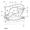
- the in the Fig. 1 and 2 Gas turbine 10 shown in the cutout has a turbine housing 11, in which a about an axis 27 rotating rotor 12th is housed.
- the compressor 17 compresses air which flows into a plenum 14.
- annular combustion chamber 15 is arranged, which is closed on the input side by a front plate cooling air 20 cooled front panel 19 and the output side via a hot gas channel 25 with the input of the turbine 13 in conjunction.
- burners 16 are arranged in a ring, which are designed for example as a double cone or EV burner and inject a fuel-air mixture into the combustion chamber 15.
- the resulting during the combustion of the mixture hot air stream 26 passes through the hot gas channel 25 in the turbine 13 and is relaxed there under work.
- the combustion chamber 15 with the hot gas channel 25 is outside with a distance surrounded by an outer and innerdehemd 21 and 31, which are fastened by means of fasteners 24 to the combustion chamber 15, 25 and between them and the combustion chamber 15, 25 each have a ring-shaped outer and inner Form cooling channel 22 and 32 respectively.
- In the cooling channels 22, 32 flows in the opposite direction to the hot gas stream 26 cooling air on the walls of the combustion chamber 15, 25 along in a combustion chamber hood 18 and from there into the burner 16 and as a faceplate cooling air 20 directly into the combustion chamber 15th
- the side walls of the combustion chamber 15, 25 are carried out either as shell elements or as solid shells (outer shell 23, inner shell 33).
- a parting plane (29 in Fig. 2a ), which allows an upper half of the shell 23, 33 (upper half shell 33a in FIG Fig. 2a ) from the lower half (lower half-shell 33b in FIG Fig. 2a ), for example, to assemble or disassemble the gas turbine rotor 12.
- the parting plane 29 has correspondingly two parting plane welding seams 30 (FIG. Fig.
- the respective lower and upper half-shells 33a, 33b have to be cooled convectively.
- the already mentioned cooling shirts (CoShirts) 21 and 31 are mounted on the half-shell cold side, which redirect ambient air and cause due to the combustion chamber pressure drop or burner pressure drop across the half-shells and thus cause a convective cooling.
- the inner and outer shell 33 and 23 of a gas turbine such as the GT13E2 are thermally and mechanically stressed during operation.
- the strength properties of the material of the shells 23, 33 are highly temperature dependent.
- the shells 23, 33 are convectively cooled.
- the shape and the high thermal load near the turbine inlet (hot gas channel 25) require, especially in this area a constant high heat transfer on the cooling air side. This is achieved in the outer shell 23 by impingement cooling.
- space and flow conditions and a seal against a cross-flow for such an impingement cooling are not given. Therefore, a conventional convection cooling is resorted to, in which the intensity of the cooling is increased by reducing the channel height of the cooling channel 32.
- the previously used configuration of the inner cooling sleeve 31 of 2 axial plates is on the one hand prone to distance tolerances and other irregularities, e.g. in the flow field before the cooling air inlet into the cooling channel, and on the other hand causes an undesirable reduction of the cooling air mass flow in the region of the smaller of the two axial plates.
- At least one of the cooling shirts on the Side on which the cooling air enters the cooling channel, to improve the Einström discipline has an outwardly curved, rounded leading edge.
- the at least one cooling shirt in the region of the leading edge is flared bell-shaped or trumpet-like.
- An embodiment of the invention is characterized in that the innerdehemd on the side on which the cooling air exiting the cooling channel, to reduce the flow losses has an outwardly curved, rounded exit edge.
- the cooling shirts are composed of individual, in the circumferential direction adjoiningdehemdsegmenten, wherein thedehemdsegmente are attached by means of distributed arranged fasteners to the associated shells.
- a preferred development is characterized in that thedehemdsegmente overlap each other in pairs in the connection areas, and that in each case adehemdsegment a pair in the overlapping region is provided with overlapping elements for a positive connection between the overlappingdehemdsegmenten.
- Another embodiment of the invention is characterized in that the fastening elements are arranged in thedehemdsegmenten in the axial direction one behind the other, and that in the axial line with the fasteners additional holes are provided in thedehemdsegmenten, through which to improve the cooling cooling air in the rays from the outside flows into the respective cooling channel.
- a further embodiment of the invention is characterized in that the combustion chamber is divided in a parting plane into an upper half with upper half shells and a lower half with lower half shells, that the half shells in the parting plane connected to each other by Trennebenenschweissnähte in that the shells have a shape deviating from the rotational symmetry in the area of the parting plane weld seams, and in that the cooling shrouds in the parting plane are adapted to the deviating shape of the shells.
- the entirety of thedehemdsegmente in firstdehemdsegmente, which adjoin the parting plane, and seconddehemdsegmente, which are outside the parting plane, divided, wherein the firstdehemdsegmente to adapt to the different shape of the shells have a raised side edge.
- Fig. 3 is shown in a side view of the part of an inner shell with segmented cooling shirt according to an embodiment of the invention.
- an annular cooling channel 32 is formed on the outside of the inner shell 33 by a concentric inner cooling jacket 31 arranged concentrically therewith, in which on the in Fig. 3 Cooling air flows in on the left side, flows to the right and leaves the cooling channel 32 on the right side (see flow arrows in Fig. 3 ).
- the innerdehemd 31 is composed of individual, extending in the axial directiondehemdsegmenten 34, which overlap each other. In the overlapping area, overlapping elements 36 protruding at the edges on the cooling-shirt segments are welded (see in particular FIG Fig. 7 ), which provide a positive fit between the overlapping segments in the overlap area.
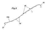
- Thedehemdsegmente 34 are distributed by means of fasteners 24 which pass through mounting holes 40 in the segments ( Fig. 5 . 6 and 8th ), attached to the associated inner shell 33.
- the fastening elements 24 are arranged one behind the other in the axial direction.
- additional holes 35 are provided in the cooling jacket segments 34 in the wake region of the fastening elements 24, flows through the air from the cooling air inlet. Due to its locally high velocity with respect to the incoming cooling air mass flow, the air jet entering the cooling channel 32 leads to an increase in the heat transfer coefficient and thus to a reduction in the wall temperature of the inner shell 33.
- the inner cooling jacket 31 is flared bell-shaped or trumpet-like in the region of the leading edge 37.
- This rounded "bellmouth-shaped" leading edge 37 of the axially one-piecede Kunststoffbleches allows on the one hand to minimize the pressure loss at the cooling air inlet and on the other an (unintended) variation of the heat transfer coefficient by detachment of the cooling air atdekanaleintritt (leading edge 37), as to Example of sharp-edged entries arise to prevent.
- the achieved by the improved inflow conditions decreases the Verwirbelungsproe lead to a reduction of the required cooling air mass flow and thus to a more efficient operation of the combustion chamber.
- the flow direction of the cooling air is opposite to the hot gas flow direction.
- the inner shell cooling shirt or inner cooling jacket 31 is further designed so that at its outlet side (trailing edge 38) a new transition radius is selected, which causes a much more favorable, ie lower, flow loss than the previous configuration.
- the reduction in the flow loss at this point is compensated by a reduction in the cooling channel height, which in turn leads to an increase in the cooling air side heat transfer and thus leads to a reduction of the average material temperature of the inner shell 33.
- the cooling jacket 31 recedes outwards in the region of the parting plane welding seams 30 and creates space for a corresponding bulge of the combustion chamber shell 33 in the region of the parting plane weld seam 39.
Landscapes
- Engineering & Computer Science (AREA)
- Chemical & Material Sciences (AREA)
- Combustion & Propulsion (AREA)
- Mechanical Engineering (AREA)
- General Engineering & Computer Science (AREA)
- Turbine Rotor Nozzle Sealing (AREA)
Applications Claiming Priority (1)
| Application Number | Priority Date | Filing Date | Title |
|---|---|---|---|
| CH01277/08A CH699309A1 (de) | 2008-08-14 | 2008-08-14 | Thermische maschine mit luftgekühlter, ringförmiger brennkammer. |
Publications (3)
| Publication Number | Publication Date |
|---|---|
| EP2154431A2 true EP2154431A2 (fr) | 2010-02-17 |
| EP2154431A3 EP2154431A3 (fr) | 2010-08-04 |
| EP2154431B1 EP2154431B1 (fr) | 2017-07-26 |
Family
ID=40342516
Family Applications (1)
| Application Number | Title | Priority Date | Filing Date |
|---|---|---|---|
| EP09167590.0A Active EP2154431B1 (fr) | 2008-08-14 | 2009-08-11 | Machine thermique |
Country Status (4)
| Country | Link |
|---|---|
| US (1) | US8434313B2 (fr) |
| EP (1) | EP2154431B1 (fr) |
| AU (1) | AU2009208110B2 (fr) |
| CH (1) | CH699309A1 (fr) |
Cited By (6)
| Publication number | Priority date | Publication date | Assignee | Title |
|---|---|---|---|---|
| EP2589873A1 (fr) * | 2011-11-04 | 2013-05-08 | General Electric Company | Chambre de combustion à flux inversé avec une injection d'air de sillage |
| WO2014099091A3 (fr) * | 2012-10-01 | 2014-08-28 | Alstom Technology Ltd. | Mécanisme de rétention de chemise thermiquement libre |
| US9267687B2 (en) | 2011-11-04 | 2016-02-23 | General Electric Company | Combustion system having a venturi for reducing wakes in an airflow |
| US9322553B2 (en) | 2013-05-08 | 2016-04-26 | General Electric Company | Wake manipulating structure for a turbine system |
| US9435221B2 (en) | 2013-08-09 | 2016-09-06 | General Electric Company | Turbomachine airfoil positioning |
| US9739201B2 (en) | 2013-05-08 | 2017-08-22 | General Electric Company | Wake reducing structure for a turbine system and method of reducing wake |
Families Citing this family (13)
| Publication number | Priority date | Publication date | Assignee | Title |
|---|---|---|---|---|
| MY161317A (en) * | 2008-02-20 | 2017-04-14 | General Electric Technology Gmbh | Gas turbine |
| US20140208771A1 (en) * | 2012-12-28 | 2014-07-31 | United Technologies Corporation | Gas turbine engine component cooling arrangement |
| EP2868898A1 (fr) * | 2013-10-30 | 2015-05-06 | Siemens Aktiengesellschaft | Mode de fonctionnement en charge partielle amélioré d'une turbine à gaz comprenant un canal d'écoulement à dérivation réglable |
| GB201501817D0 (en) * | 2015-02-04 | 2015-03-18 | Rolls Royce Plc | A combustion chamber and a combustion chamber segment |
| EP3236155B1 (fr) * | 2016-04-22 | 2020-05-06 | Rolls-Royce plc | Chambre de combustion à paroi segmentée |
| US10641174B2 (en) | 2017-01-18 | 2020-05-05 | General Electric Company | Rotor shaft cooling |
| US10801730B2 (en) | 2017-04-12 | 2020-10-13 | Raytheon Technologies Corporation | Combustor panel mounting systems and methods |
| US10697634B2 (en) * | 2018-03-07 | 2020-06-30 | General Electric Company | Inner cooling shroud for transition zone of annular combustor liner |
| US11377970B2 (en) | 2018-11-02 | 2022-07-05 | Chromalloy Gas Turbine Llc | System and method for providing compressed air to a gas turbine combustor |
| EP3874129A4 (fr) * | 2018-11-02 | 2022-10-05 | Chromalloy Gas Turbine LLC | Système et procédé pour fournir de l'air comprimé à une chambre de combustion de turbine à gaz |
| US11248797B2 (en) | 2018-11-02 | 2022-02-15 | Chromalloy Gas Turbine Llc | Axial stop configuration for a combustion liner |
| US11047575B2 (en) * | 2019-04-15 | 2021-06-29 | Raytheon Technologies Corporation | Combustor heat shield panel |
| US11215367B2 (en) | 2019-10-03 | 2022-01-04 | Raytheon Technologies Corporation | Mounting a ceramic component to a non-ceramic component in a gas turbine engine |
Family Cites Families (13)
| Publication number | Priority date | Publication date | Assignee | Title |
|---|---|---|---|---|
| JPH0752014B2 (ja) * | 1986-03-20 | 1995-06-05 | 株式会社日立製作所 | ガスタ−ビン燃焼器 |
| US4896510A (en) * | 1987-02-06 | 1990-01-30 | General Electric Company | Combustor liner cooling arrangement |
| EP0489193B1 (fr) * | 1990-12-05 | 1997-07-23 | Asea Brown Boveri Ag | Chambre de combustion pour turbine à gaz |
| DE4232442A1 (de) * | 1992-09-28 | 1994-03-31 | Asea Brown Boveri | Gasturbinenbrennkammer |
| DE4239856A1 (de) * | 1992-11-27 | 1994-06-01 | Asea Brown Boveri | Gasturbinenbrennkammer |
| DE4242721A1 (de) * | 1992-12-17 | 1994-06-23 | Asea Brown Boveri | Gasturbinenbrennkammer |
| DE19751299C2 (de) * | 1997-11-19 | 1999-09-09 | Siemens Ag | Brennkammer sowie Verfahren zur Dampfkühlung einer Brennkammer |
| DE59810347D1 (de) * | 1998-09-10 | 2004-01-15 | Alstom Switzerland Ltd | Schwingungsdämpfung in Brennkammern |
| EP1001224B1 (fr) * | 1998-11-12 | 2006-03-22 | Mitsubishi Heavy Industries, Ltd. | Chambre de combustion pour une turbine à gaz |
| JP2002195565A (ja) * | 2000-12-26 | 2002-07-10 | Mitsubishi Heavy Ind Ltd | ガスタービン燃焼器 |
| US7082770B2 (en) * | 2003-12-24 | 2006-08-01 | Martling Vincent C | Flow sleeve for a low NOx combustor |
| GB2420614B (en) * | 2004-11-30 | 2009-06-03 | Alstom Technology Ltd | Tile and exo-skeleton tile structure |
| GB2434199B (en) * | 2006-01-14 | 2011-01-05 | Alstom Technology Ltd | Combustor liner with heat shield |
-
2008
- 2008-08-14 CH CH01277/08A patent/CH699309A1/de not_active Application Discontinuation
-
2009
- 2009-08-11 AU AU2009208110A patent/AU2009208110B2/en not_active Ceased
- 2009-08-11 EP EP09167590.0A patent/EP2154431B1/fr active Active
- 2009-08-13 US US12/540,453 patent/US8434313B2/en active Active
Cited By (8)
| Publication number | Priority date | Publication date | Assignee | Title |
|---|---|---|---|---|
| EP2589873A1 (fr) * | 2011-11-04 | 2013-05-08 | General Electric Company | Chambre de combustion à flux inversé avec une injection d'air de sillage |
| US8899975B2 (en) | 2011-11-04 | 2014-12-02 | General Electric Company | Combustor having wake air injection |
| US9267687B2 (en) | 2011-11-04 | 2016-02-23 | General Electric Company | Combustion system having a venturi for reducing wakes in an airflow |
| WO2014099091A3 (fr) * | 2012-10-01 | 2014-08-28 | Alstom Technology Ltd. | Mécanisme de rétention de chemise thermiquement libre |
| CN104685296A (zh) * | 2012-10-01 | 2015-06-03 | 阿尔斯通技术有限公司 | 热自由衬套固持机构 |
| US9322553B2 (en) | 2013-05-08 | 2016-04-26 | General Electric Company | Wake manipulating structure for a turbine system |
| US9739201B2 (en) | 2013-05-08 | 2017-08-22 | General Electric Company | Wake reducing structure for a turbine system and method of reducing wake |
| US9435221B2 (en) | 2013-08-09 | 2016-09-06 | General Electric Company | Turbomachine airfoil positioning |
Also Published As
| Publication number | Publication date |
|---|---|
| US20100037621A1 (en) | 2010-02-18 |
| CH699309A1 (de) | 2010-02-15 |
| US8434313B2 (en) | 2013-05-07 |
| EP2154431A3 (fr) | 2010-08-04 |
| EP2154431B1 (fr) | 2017-07-26 |
| AU2009208110A1 (en) | 2010-03-04 |
| AU2009208110B2 (en) | 2014-07-10 |
Similar Documents
| Publication | Publication Date | Title |
|---|---|---|
| EP2154431B1 (fr) | Machine thermique | |
| DE102005025823B4 (de) | Verfahren und Vorrichtung zum Kühlen einer Brennkammerauskleidung und eines Übergangsteils einer Gasturbine | |
| EP2423599B1 (fr) | Procédé de fonctionnement d'un agencement de brûleur ainsi qu'agencement de brûleur destiné à la mise en oeuvre du procédé | |
| EP2340397B1 (fr) | Pièce du brûleur pour une chambre de combustion d'une turbine à gaz et turbine à gaz | |
| CH697920A2 (de) | Turbinentriebwerk mit einer Brennkammerauskleidung mit wirbelluftgekühltem hinterem Ende und Kühlverfahren. | |
| DE69006861T2 (de) | Brenner und Brennstoffinjektor-Anordnung. | |
| DE69102032T2 (de) | Gasturbinenbrennkammer. | |
| EP2242955B1 (fr) | Turbine à gaz à chambre de combustion annulaire et procédé d'assemblage | |
| EP2242916B1 (fr) | Turbine à gaz | |
| EP2808611B1 (fr) | Injecteur pour l'introduction d'un mélange air-carburant dans une chambre de combustion | |
| DE19538746B4 (de) | Segmentierter Mittelkörper für eine Doppelring-Brennkammer | |
| EP2559942A1 (fr) | Tête de chambre de combustion d'une turbine à gaz dotée d'un refroidissement et d'un amortissement | |
| DE3309268C2 (fr) | ||
| CH709993A2 (de) | Stromabwärtige Düse in einer Brennkammer einer Verbrennungsturbine. | |
| EP1865259A2 (fr) | Paroi de chambre de combustion de turbine à gaz pour une chambre de turbine à gaz à combustion pauvre | |
| DE102012015449A1 (de) | Gasturbinenbrennkammer mit Mischluftöffnungen und Luftleitelementen in modularer Bauweise | |
| DE4223733C2 (de) | Verbindung von Mischrohr und Flammrohr einer Gasturbine | |
| DE102011055109A1 (de) | Anlage zum Lenken des Luftstroms in einer Kraftstoffdüsenanordnung | |
| WO2016156370A1 (fr) | Élément de protection thermique par déviation | |
| CH705514A1 (de) | Gaskanal für eine Gasturbine sowie Gasturbine mit einem solchen Gaskanal. | |
| EP0636764A1 (fr) | Turbine à gaz avec refroidissement du rotor | |
| EP2852735A2 (fr) | Turbine à gaz | |
| DE102015113009A1 (de) | Brennkammerkappenanordnung | |
| EP1724526A1 (fr) | Coquille de turbine à gaz, turbine à gaz et procédé de démarrage et d'arrêt d'une turbine à gaz | |
| EP2459934A2 (fr) | Chambre de combustion de turbine à gaz |
Legal Events
| Date | Code | Title | Description |
|---|---|---|---|
| PUAI | Public reference made under article 153(3) epc to a published international application that has entered the european phase |
Free format text: ORIGINAL CODE: 0009012 |
|
| AK | Designated contracting states |
Kind code of ref document: A2 Designated state(s): AT BE BG CH CY CZ DE DK EE ES FI FR GB GR HR HU IE IS IT LI LT LU LV MC MK MT NL NO PL PT RO SE SI SK SM TR |
|
| AX | Request for extension of the european patent |
Extension state: AL BA RS |
|
| PUAL | Search report despatched |
Free format text: ORIGINAL CODE: 0009013 |
|
| AK | Designated contracting states |
Kind code of ref document: A3 Designated state(s): AT BE BG CH CY CZ DE DK EE ES FI FR GB GR HR HU IE IS IT LI LT LU LV MC MK MT NL NO PL PT RO SE SI SK SM TR |
|
| AX | Request for extension of the european patent |
Extension state: AL BA RS |
|
| 17P | Request for examination filed |
Effective date: 20110125 |
|
| RAP1 | Party data changed (applicant data changed or rights of an application transferred) |
Owner name: GENERAL ELECTRIC TECHNOLOGY GMBH |
|
| GRAP | Despatch of communication of intention to grant a patent |
Free format text: ORIGINAL CODE: EPIDOSNIGR1 |
|
| INTG | Intention to grant announced |
Effective date: 20170310 |
|
| GRAS | Grant fee paid |
Free format text: ORIGINAL CODE: EPIDOSNIGR3 |
|
| GRAA | (expected) grant |
Free format text: ORIGINAL CODE: 0009210 |
|
| AK | Designated contracting states |
Kind code of ref document: B1 Designated state(s): AT BE BG CH CY CZ DE DK EE ES FI FR GB GR HR HU IE IS IT LI LT LU LV MC MK MT NL NO PL PT RO SE SI SK SM TR |
|
| REG | Reference to a national code |
Ref country code: GB Ref legal event code: FG4D Free format text: NOT ENGLISH |
|
| REG | Reference to a national code |
Ref country code: CH Ref legal event code: EP |
|
| REG | Reference to a national code |
Ref country code: AT Ref legal event code: REF Ref document number: 912692 Country of ref document: AT Kind code of ref document: T Effective date: 20170815 |
|
| REG | Reference to a national code |
Ref country code: IE Ref legal event code: FG4D Free format text: LANGUAGE OF EP DOCUMENT: GERMAN |
|
| REG | Reference to a national code |
Ref country code: DE Ref legal event code: R096 Ref document number: 502009014186 Country of ref document: DE |
|
| REG | Reference to a national code |
Ref country code: NL Ref legal event code: MP Effective date: 20170726 |
|
| REG | Reference to a national code |
Ref country code: LT Ref legal event code: MG4D |
|
| PG25 | Lapsed in a contracting state [announced via postgrant information from national office to epo] |
Ref country code: SE Free format text: LAPSE BECAUSE OF FAILURE TO SUBMIT A TRANSLATION OF THE DESCRIPTION OR TO PAY THE FEE WITHIN THE PRESCRIBED TIME-LIMIT Effective date: 20170726 Ref country code: HR Free format text: LAPSE BECAUSE OF FAILURE TO SUBMIT A TRANSLATION OF THE DESCRIPTION OR TO PAY THE FEE WITHIN THE PRESCRIBED TIME-LIMIT Effective date: 20170726 Ref country code: FI Free format text: LAPSE BECAUSE OF FAILURE TO SUBMIT A TRANSLATION OF THE DESCRIPTION OR TO PAY THE FEE WITHIN THE PRESCRIBED TIME-LIMIT Effective date: 20170726 Ref country code: NL Free format text: LAPSE BECAUSE OF FAILURE TO SUBMIT A TRANSLATION OF THE DESCRIPTION OR TO PAY THE FEE WITHIN THE PRESCRIBED TIME-LIMIT Effective date: 20170726 Ref country code: LT Free format text: LAPSE BECAUSE OF FAILURE TO SUBMIT A TRANSLATION OF THE DESCRIPTION OR TO PAY THE FEE WITHIN THE PRESCRIBED TIME-LIMIT Effective date: 20170726 Ref country code: NO Free format text: LAPSE BECAUSE OF FAILURE TO SUBMIT A TRANSLATION OF THE DESCRIPTION OR TO PAY THE FEE WITHIN THE PRESCRIBED TIME-LIMIT Effective date: 20171026 |
|
| PG25 | Lapsed in a contracting state [announced via postgrant information from national office to epo] |
Ref country code: GR Free format text: LAPSE BECAUSE OF FAILURE TO SUBMIT A TRANSLATION OF THE DESCRIPTION OR TO PAY THE FEE WITHIN THE PRESCRIBED TIME-LIMIT Effective date: 20171027 Ref country code: LV Free format text: LAPSE BECAUSE OF FAILURE TO SUBMIT A TRANSLATION OF THE DESCRIPTION OR TO PAY THE FEE WITHIN THE PRESCRIBED TIME-LIMIT Effective date: 20170726 Ref country code: IS Free format text: LAPSE BECAUSE OF FAILURE TO SUBMIT A TRANSLATION OF THE DESCRIPTION OR TO PAY THE FEE WITHIN THE PRESCRIBED TIME-LIMIT Effective date: 20171126 Ref country code: BG Free format text: LAPSE BECAUSE OF FAILURE TO SUBMIT A TRANSLATION OF THE DESCRIPTION OR TO PAY THE FEE WITHIN THE PRESCRIBED TIME-LIMIT Effective date: 20171026 Ref country code: PL Free format text: LAPSE BECAUSE OF FAILURE TO SUBMIT A TRANSLATION OF THE DESCRIPTION OR TO PAY THE FEE WITHIN THE PRESCRIBED TIME-LIMIT Effective date: 20170726 Ref country code: ES Free format text: LAPSE BECAUSE OF FAILURE TO SUBMIT A TRANSLATION OF THE DESCRIPTION OR TO PAY THE FEE WITHIN THE PRESCRIBED TIME-LIMIT Effective date: 20170726 |
|
| REG | Reference to a national code |
Ref country code: CH Ref legal event code: PL |
|
| PG25 | Lapsed in a contracting state [announced via postgrant information from national office to epo] |
Ref country code: CZ Free format text: LAPSE BECAUSE OF FAILURE TO SUBMIT A TRANSLATION OF THE DESCRIPTION OR TO PAY THE FEE WITHIN THE PRESCRIBED TIME-LIMIT Effective date: 20170726 Ref country code: CH Free format text: LAPSE BECAUSE OF NON-PAYMENT OF DUE FEES Effective date: 20170831 Ref country code: DK Free format text: LAPSE BECAUSE OF FAILURE TO SUBMIT A TRANSLATION OF THE DESCRIPTION OR TO PAY THE FEE WITHIN THE PRESCRIBED TIME-LIMIT Effective date: 20170726 Ref country code: MC Free format text: LAPSE BECAUSE OF FAILURE TO SUBMIT A TRANSLATION OF THE DESCRIPTION OR TO PAY THE FEE WITHIN THE PRESCRIBED TIME-LIMIT Effective date: 20170726 Ref country code: LI Free format text: LAPSE BECAUSE OF NON-PAYMENT OF DUE FEES Effective date: 20170831 Ref country code: RO Free format text: LAPSE BECAUSE OF FAILURE TO SUBMIT A TRANSLATION OF THE DESCRIPTION OR TO PAY THE FEE WITHIN THE PRESCRIBED TIME-LIMIT Effective date: 20170726 |
|
| REG | Reference to a national code |
Ref country code: DE Ref legal event code: R097 Ref document number: 502009014186 Country of ref document: DE |
|
| REG | Reference to a national code |
Ref country code: IE Ref legal event code: MM4A |
|
| PG25 | Lapsed in a contracting state [announced via postgrant information from national office to epo] |
Ref country code: SK Free format text: LAPSE BECAUSE OF FAILURE TO SUBMIT A TRANSLATION OF THE DESCRIPTION OR TO PAY THE FEE WITHIN THE PRESCRIBED TIME-LIMIT Effective date: 20170726 Ref country code: EE Free format text: LAPSE BECAUSE OF FAILURE TO SUBMIT A TRANSLATION OF THE DESCRIPTION OR TO PAY THE FEE WITHIN THE PRESCRIBED TIME-LIMIT Effective date: 20170726 Ref country code: SM Free format text: LAPSE BECAUSE OF FAILURE TO SUBMIT A TRANSLATION OF THE DESCRIPTION OR TO PAY THE FEE WITHIN THE PRESCRIBED TIME-LIMIT Effective date: 20170726 |
|
| PLBE | No opposition filed within time limit |
Free format text: ORIGINAL CODE: 0009261 |
|
| STAA | Information on the status of an ep patent application or granted ep patent |
Free format text: STATUS: NO OPPOSITION FILED WITHIN TIME LIMIT |
|
| REG | Reference to a national code |
Ref country code: BE Ref legal event code: MM Effective date: 20170831 |
|
| GBPC | Gb: european patent ceased through non-payment of renewal fee |
Effective date: 20171026 |
|
| PG25 | Lapsed in a contracting state [announced via postgrant information from national office to epo] |
Ref country code: LU Free format text: LAPSE BECAUSE OF NON-PAYMENT OF DUE FEES Effective date: 20170811 |
|
| 26N | No opposition filed |
Effective date: 20180430 |
|
| REG | Reference to a national code |
Ref country code: FR Ref legal event code: ST Effective date: 20180606 |
|
| PG25 | Lapsed in a contracting state [announced via postgrant information from national office to epo] |
Ref country code: IE Free format text: LAPSE BECAUSE OF NON-PAYMENT OF DUE FEES Effective date: 20170811 Ref country code: GB Free format text: LAPSE BECAUSE OF NON-PAYMENT OF DUE FEES Effective date: 20171026 |
|
| PG25 | Lapsed in a contracting state [announced via postgrant information from national office to epo] |
Ref country code: FR Free format text: LAPSE BECAUSE OF NON-PAYMENT OF DUE FEES Effective date: 20170926 Ref country code: SI Free format text: LAPSE BECAUSE OF FAILURE TO SUBMIT A TRANSLATION OF THE DESCRIPTION OR TO PAY THE FEE WITHIN THE PRESCRIBED TIME-LIMIT Effective date: 20170726 Ref country code: BE Free format text: LAPSE BECAUSE OF NON-PAYMENT OF DUE FEES Effective date: 20170831 |
|
| PG25 | Lapsed in a contracting state [announced via postgrant information from national office to epo] |
Ref country code: MT Free format text: LAPSE BECAUSE OF FAILURE TO SUBMIT A TRANSLATION OF THE DESCRIPTION OR TO PAY THE FEE WITHIN THE PRESCRIBED TIME-LIMIT Effective date: 20170726 |
|
| REG | Reference to a national code |
Ref country code: AT Ref legal event code: MM01 Ref document number: 912692 Country of ref document: AT Kind code of ref document: T Effective date: 20170811 |
|
| PG25 | Lapsed in a contracting state [announced via postgrant information from national office to epo] |
Ref country code: AT Free format text: LAPSE BECAUSE OF NON-PAYMENT OF DUE FEES Effective date: 20170811 |
|
| PG25 | Lapsed in a contracting state [announced via postgrant information from national office to epo] |
Ref country code: HU Free format text: LAPSE BECAUSE OF FAILURE TO SUBMIT A TRANSLATION OF THE DESCRIPTION OR TO PAY THE FEE WITHIN THE PRESCRIBED TIME-LIMIT; INVALID AB INITIO Effective date: 20090811 |
|
| PG25 | Lapsed in a contracting state [announced via postgrant information from national office to epo] |
Ref country code: CY Free format text: LAPSE BECAUSE OF NON-PAYMENT OF DUE FEES Effective date: 20170726 |
|
| PG25 | Lapsed in a contracting state [announced via postgrant information from national office to epo] |
Ref country code: MK Free format text: LAPSE BECAUSE OF FAILURE TO SUBMIT A TRANSLATION OF THE DESCRIPTION OR TO PAY THE FEE WITHIN THE PRESCRIBED TIME-LIMIT Effective date: 20170726 |
|
| PG25 | Lapsed in a contracting state [announced via postgrant information from national office to epo] |
Ref country code: TR Free format text: LAPSE BECAUSE OF FAILURE TO SUBMIT A TRANSLATION OF THE DESCRIPTION OR TO PAY THE FEE WITHIN THE PRESCRIBED TIME-LIMIT Effective date: 20170726 |
|
| PG25 | Lapsed in a contracting state [announced via postgrant information from national office to epo] |
Ref country code: PT Free format text: LAPSE BECAUSE OF FAILURE TO SUBMIT A TRANSLATION OF THE DESCRIPTION OR TO PAY THE FEE WITHIN THE PRESCRIBED TIME-LIMIT Effective date: 20170726 |
|
| P01 | Opt-out of the competence of the unified patent court (upc) registered |
Effective date: 20230522 |
|
| PGFP | Annual fee paid to national office [announced via postgrant information from national office to epo] |
Ref country code: DE Payment date: 20250724 Year of fee payment: 17 |
|
| PGFP | Annual fee paid to national office [announced via postgrant information from national office to epo] |
Ref country code: IT Payment date: 20250723 Year of fee payment: 17 |