EP2590293A1 - Kontaktloses Stromübertragungssystem mit Überhitzungsschutzfunktion und Verfahren dafür - Google Patents
Kontaktloses Stromübertragungssystem mit Überhitzungsschutzfunktion und Verfahren dafür Download PDFInfo
- Publication number
- EP2590293A1 EP2590293A1 EP20120190889 EP12190889A EP2590293A1 EP 2590293 A1 EP2590293 A1 EP 2590293A1 EP 20120190889 EP20120190889 EP 20120190889 EP 12190889 A EP12190889 A EP 12190889A EP 2590293 A1 EP2590293 A1 EP 2590293A1
- Authority
- EP
- European Patent Office
- Prior art keywords
- power
- contactless power
- signal
- transmitting
- contactless
- Prior art date
- Legal status (The legal status is an assumption and is not a legal conclusion. Google has not performed a legal analysis and makes no representation as to the accuracy of the status listed.)
- Granted
Links
Images


Classifications
-
- H—ELECTRICITY
- H02—GENERATION; CONVERSION OR DISTRIBUTION OF ELECTRIC POWER
- H02J—ELECTRIC POWER NETWORKS; CIRCUIT ARRANGEMENTS OR SYSTEMS FOR SUPPLYING OR DISTRIBUTING ELECTRIC POWER; SYSTEMS FOR STORING ELECTRIC ENERGY
- H02J7/00—Circuit arrangements for charging or discharging batteries or for supplying loads from batteries
- H02J7/60—Circuit arrangements for charging or discharging batteries or for supplying loads from batteries including safety or protection arrangements
- H02J7/65—Circuit arrangements for charging or discharging batteries or for supplying loads from batteries including safety or protection arrangements against overtemperature
-
- H—ELECTRICITY
- H02—GENERATION; CONVERSION OR DISTRIBUTION OF ELECTRIC POWER
- H02J—ELECTRIC POWER NETWORKS; CIRCUIT ARRANGEMENTS OR SYSTEMS FOR SUPPLYING OR DISTRIBUTING ELECTRIC POWER; SYSTEMS FOR STORING ELECTRIC ENERGY
- H02J50/00—Circuit arrangements or systems for wireless supply or distribution of electric power
- H02J50/10—Circuit arrangements or systems for wireless supply or distribution of electric power using inductive coupling
-
- H—ELECTRICITY
- H02—GENERATION; CONVERSION OR DISTRIBUTION OF ELECTRIC POWER
- H02J—ELECTRIC POWER NETWORKS; CIRCUIT ARRANGEMENTS OR SYSTEMS FOR SUPPLYING OR DISTRIBUTING ELECTRIC POWER; SYSTEMS FOR STORING ELECTRIC ENERGY
- H02J50/00—Circuit arrangements or systems for wireless supply or distribution of electric power
- H02J50/10—Circuit arrangements or systems for wireless supply or distribution of electric power using inductive coupling
- H02J50/12—Circuit arrangements or systems for wireless supply or distribution of electric power using inductive coupling of the resonant type
-
- H—ELECTRICITY
- H02—GENERATION; CONVERSION OR DISTRIBUTION OF ELECTRIC POWER
- H02J—ELECTRIC POWER NETWORKS; CIRCUIT ARRANGEMENTS OR SYSTEMS FOR SUPPLYING OR DISTRIBUTING ELECTRIC POWER; SYSTEMS FOR STORING ELECTRIC ENERGY
- H02J50/00—Circuit arrangements or systems for wireless supply or distribution of electric power
- H02J50/80—Circuit arrangements or systems for wireless supply or distribution of electric power involving the exchange of data, concerning supply or distribution of electric power, between transmitting devices and receiving devices
-
- H—ELECTRICITY
- H02—GENERATION; CONVERSION OR DISTRIBUTION OF ELECTRIC POWER
- H02J—ELECTRIC POWER NETWORKS; CIRCUIT ARRANGEMENTS OR SYSTEMS FOR SUPPLYING OR DISTRIBUTING ELECTRIC POWER; SYSTEMS FOR STORING ELECTRIC ENERGY
- H02J7/00—Circuit arrangements for charging or discharging batteries or for supplying loads from batteries
- H02J7/90—Regulation of charging or discharging current or voltage
- H02J7/971—Regulation of charging or discharging current or voltage the charge cycle being controlled or terminated in response to non-electric parameters
- H02J7/975—Regulation of charging or discharging current or voltage the charge cycle being controlled or terminated in response to non-electric parameters in response to temperature
-
- H—ELECTRICITY
- H02—GENERATION; CONVERSION OR DISTRIBUTION OF ELECTRIC POWER
- H02J—ELECTRIC POWER NETWORKS; CIRCUIT ARRANGEMENTS OR SYSTEMS FOR SUPPLYING OR DISTRIBUTING ELECTRIC POWER; SYSTEMS FOR STORING ELECTRIC ENERGY
- H02J7/00—Circuit arrangements for charging or discharging batteries or for supplying loads from batteries
- H02J7/90—Regulation of charging or discharging current or voltage
- H02J7/971—Regulation of charging or discharging current or voltage the charge cycle being controlled or terminated in response to non-electric parameters
- H02J7/975—Regulation of charging or discharging current or voltage the charge cycle being controlled or terminated in response to non-electric parameters in response to temperature
- H02J7/977—Regulation of charging or discharging current or voltage the charge cycle being controlled or terminated in response to non-electric parameters in response to temperature of the battery
-
- H—ELECTRICITY
- H02—GENERATION; CONVERSION OR DISTRIBUTION OF ELECTRIC POWER
- H02J—ELECTRIC POWER NETWORKS; CIRCUIT ARRANGEMENTS OR SYSTEMS FOR SUPPLYING OR DISTRIBUTING ELECTRIC POWER; SYSTEMS FOR STORING ELECTRIC ENERGY
- H02J7/00—Circuit arrangements for charging or discharging batteries or for supplying loads from batteries
- H02J7/40—Circuit arrangements for charging or discharging batteries or for supplying loads from batteries characterised by the exchange of charge or discharge related data
- H02J7/443—Circuit arrangements for charging or discharging batteries or for supplying loads from batteries characterised by the exchange of charge or discharge related data using passive battery identification means, e.g. resistors or capacitors
- H02J7/445—Circuit arrangements for charging or discharging batteries or for supplying loads from batteries characterised by the exchange of charge or discharge related data using passive battery identification means, e.g. resistors or capacitors in response to measured battery parameters, e.g. voltage, current or temperature profile
-
- H—ELECTRICITY
- H02—GENERATION; CONVERSION OR DISTRIBUTION OF ELECTRIC POWER
- H02J—ELECTRIC POWER NETWORKS; CIRCUIT ARRANGEMENTS OR SYSTEMS FOR SUPPLYING OR DISTRIBUTING ELECTRIC POWER; SYSTEMS FOR STORING ELECTRIC ENERGY
- H02J7/00—Circuit arrangements for charging or discharging batteries or for supplying loads from batteries
- H02J7/40—Circuit arrangements for charging or discharging batteries or for supplying loads from batteries characterised by the exchange of charge or discharge related data
- H02J7/47—Arrangements for checking compatibility or authentication between one component, e.g. a battery or a battery charger, and another component, e.g. a power source
Definitions
- the present invention relates to a contactless power transmitting system having an overheat protection function of allowing a battery cell module not to be damaged due to overheat in the case in which a power is charged in the battery cell module, and a method thereof.
- a portable terminal such as a cellular phone, a personal digital assistant (PDA), or the like, has been mounted with a battery pack.
- the battery pack may be charged with a power supplied from an external charging apparatus and supply the charged power to the portable terminal to operate the portable terminal according to a manipulation of a user.
- the battery pack may include a battery cell module charged with the power, a charging and discharging circuit charging the power in the battery cell module and discharging the power charged in the battery cell module, and the like.
- the instantaneous discharge phenomenon causes abrasion of the terminal of the battery pack and the terminal of the charging apparatus and causes a risk of an accident such as a fire, or the like, in the case in which foreign materials are accumulated in the terminal of the battery pack and the terminal of the charging apparatus.
- the electrical energy charged in the battery pack is naturally discharged to the outside through the terminal of the battery pack due to moisture, or the like, such that a lifespan of the battery pack may be decreased and performance thereof may be deteriorated.
- An object of the present invention is to provide a contactless power transmitting system having an overheat protection function of protecting a battery cell module so as not to be damaged due to overheat in the case in which a power is charged in the battery cell module in the contactless power transmitting system, and a method thereof.
- Another object of the present invention is to provide a contactless power transmitting system having an overheat protection function of protecting a battery cell module so as not to be damaged due to overheat by allowing a contactless power transmitting apparatus to transmit a first power to a contactless power receiving apparatus to charge the first power in the battery cell module and transmit a second power lower than the first power to the contactless power receiving apparatus to charge the second power in the battery cell module in the case in which the battery cell module is overheated to a predetermined temperature or more, and a method thereof.
- the contactless power receiving apparatus judges whether or not the battery cell module has been overheated.
- the judging of whether or not the battery cell module has been overheated may be performed by a process of detecting a first temperature of the battery cell module using a first temperature sensor and judging that the battery cell module has been overheated in the case in which the detected first temperature is equal to or higher than a preset temperature,
- the judging of whether or not the battery cell module has been overheated may be performed by a process of detecting a first temperature of the battery cell module using a first temperature sensor, detecting a second temperature of the outside using a second temperature sensor and judging that the battery cell module has been overheated in the case in which the first temperature is higher than the second temperature by a preset temperature our more.
- the contactless power receiving apparatus In the case in which it is judged that the battery cell module has been overheated, the contactless power receiving apparatus generates an overheat alarm signal to transmit the generated contactless power to the contactless power transmitting apparatus.
- the contactless power transmitting apparatus transmits a second power lower than the first power to the contactless power receiving apparatus in the case in which the overheat alarm signal is received from the contactless power receiving apparatus to charge the second power in the battery cell module, thereby allowing the battery cell module not to be overheated.
- the charging apparatus is switched into a second power charging mode in which the second power is charged in the battery cell module, thereby preventing generation of an error.
- a contactless power transmitting apparatus having an overheat protection function, including: a power transmitting unit including a power transmitting coil transmitting a power to a contactless power receiving apparatus; a first signal receiving unit receiving an overheat alarm signal transmitted by the contactless power receiving apparatus; and a contactless power transmission controlling unit controlling the power transmitting unit to transmit a first power to the contactless power receiving apparatus and controlling the power transmitting unit to transmits a second power lower than the first power to the contactless power receiving apparatus in the case in which the first signal receiving unit receives the overheat alarm signal.
- the power transmitting unit may include: a driving driver generating a driving signal for transmitting the first power or the second power under a control of the contactless power transmission controlling unit; a series resonant converter switching a direct current (DC) power according to the driving signal; and the power transmitting coil transmitting the first power or the second power to the contactless power receiving apparatus while being resonated with the power switched by the series resonant converter.
- a driving driver generating a driving signal for transmitting the first power or the second power under a control of the contactless power transmission controlling unit
- DC direct current
- the contactless power transmitting apparatus having an overheat protection function may further include a first signal transmitting unit generating an identification (ID) request signal under a control of the contactless power transmission controlling unit to transmit the generated ID signal to the contactless power receiving apparatus, wherein the first signal receiving unit receives an ID signal transmitted by the contactless power receiving apparatus according to the ID request signal to provide the received ID signal to the contactless power transmission controlling unit.
- ID identification
- a contactless power receiving apparatus having an overheat protection function, including: a charging apparatus receiving a first power transmitted by a contactless power transmitting apparatus to charge the first power in a battery cell module; a second signal transmitting unit generating an overheat alarm signal to transmit the overheat alarm signal to the contactless power transmitting apparatus; and a contactless power reception controlling unit judging whether or not the battery cell module has been overheated, and controlling the second signal transmitting unit to generate the overheat alarm signal to transmit the generated overheat alarm signal to the contactless power transmitting apparatus and then controlling the charging apparatus to receive a second power lower than the first power from the contactless power transmitting apparatus to charge the second power in the battery cell module, in the case in which it is judged that the battery cell module has been overheated.
- the contactless power receiving apparatus having an overheat protection function may further include a first temperature sensor detecting a first temperature of the battery cell module, wherein the contactless power reception controlling unit judges whether or not the battery cell module has been overheated using the first temperature.
- the contactless power receiving apparatus having an overheat protection function may further include a second temperature sensor detecting a second temperature of the outside, wherein the contactless power reception controlling unit judges that the battery cell module has been overheated in the case in which a difference between the first and second temperatures is larger than a preset value.
- the contactless power receiving apparatus having an overheat protection function may further include a second signal receiving unit receiving an ID request signal transmitted by the contactless power transmitting apparatus to provide the ID request signal to the contactless power reception controlling unit, wherein the second signal transmitting unit generates an ID signal under a control of the contactless power reception controlling unit to transmit the generated ID request signal to the contactless power transmitting apparatus, in the case in which the ID request signal is received.
- the charging apparatus may include: a power receiving coil receiving the first power or the second power transmitted by the contactless power transmitting apparatus; a rectifying unit converting the first power or the second power received by the power receiving coil into a DC power; and a charging unit charging the DC power rectified by the rectifying unit in the battery cell module under a control of the contactless power reception controlling unit.
- a contactless power receiving method having an overheat protection function including: transmitting, in a contactless power transmitting apparatus, a first power to a contactless power receiving apparatus through a power transmitting coil; and transmitting, in the contactless power transmitting apparatus, a second power lower than the first power to the contactless power receiving apparatus through the power transmitting coil in the case in which an overheat alarm signal is received from the contactless power receiving apparatus.
- the transmitting of the first power may include: transmitting, in the contactless power transmitting apparatus, an ID request signal to the contactless power receiving apparatus; and transmitting the first power in the case in which an ID signal is received from the contactless power receiving apparatus according to the ID request signal.
- the transmitting of the ID request signal may include: judging whether or not a change in a load has been generated in the power transmitting coil; and transmitting the ID request signal in the case in which it is judged that the change in the load has been generated in the power transmitting coil.
- the contactless power transmitting method having an overheat protection function may further include, in a contactless power transmission controlling unit, stopping the transmission of the power in the case in which a charging completion signal is received from the contactless power receiving apparatus.
- a contactless power transmitting method having an overheat protection function, including: receiving, in a charging apparatus, a first power transmitted by a contactless power transmitting apparatus to charge the first power in a battery cell module; judging, in a contactless power reception controlling unit, whether or not the battery cell module has been overheated; and transmitting, in the contactless power reception controlling unit, an overheat alarm signal to the contactless power transmitting apparatus and then receiving, in the charging apparatus, a second power lower than the first power to charge the second power in the battery cell module, in the case in which it is judged that the battery cell module has been overheated.
- the judging of whether or not the battery cell module has been overheated may include: detecting, in a first temperature sensor, a first temperature of the battery cell module; and judging that the battery cell module has been overheated in the case in which the first temperature is equal to or higher than a preset temperature.
- the judging of whether or not the battery cell module has been overheated may include: detecting, in a first temperature sensor, a first temperature of the battery cell module; detecting, in a second temperature sensor, a second temperature of the outside; and judging that the battery cell module has been overheated in the case in which a difference between the first and second temperatures is larger than a preset value.
- the contactless power receiving method having an overheat protection function may further include: judging, in the contactless power reception controlling unit, whether or not the charging of the battery cell module has been completed; and generating a charging completion signal to transmit the generated charging completion signal to the contactless power transmitting apparatus in the case in which it is judged that the charging of the battery cell module has been completed.
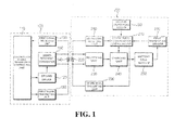
- FIG. 1 is a view showing a configuration of a contactless power transmitting system having an overheat protection function according to an exemplary embodiment of the present
- the contactless power transmitting system having an overheat protection function according to the exemplary embodiment of the present invention may be configured to include a contactless power transmitting apparatus 100 and a contactless power receiving apparatus 200.
- the contactless power transmitting apparatus 100 transmit a power using an electromagnetic induction scheme, and the contactless power receiving apparatus 200 receives the power using the electromagnetic induction scheme. More specifically, the contactless power transmitting apparatus 100 transmits a first power or a second power lower than the first power without a contact, and the contactless power receiving apparatus 200 receives the first power on the second power transmitted hy the contactless power transmitting apparatus 100 without the contact to charge the first power or the second power in a battery cell module 250 or supply an operation power to a load such as a portable terminal, or the like, including the contactless power receiving apparatus 200.
- the contactless power transmitting apparatus 100 is operated by a direct current (DC) power supplied by an alternate current (AC) to DC converter (not shown), wherein the AC to DC converter may be provided separately from the contactless power transmitting apparatus 100 or provided integrally with the contactless power transmitting apparatus 100.
- DC direct current
- AC alternate current
- the contactless power transmitting apparatus 100 may include a contactless power transmission controlling unit 110, a power transmitting unit, a first signal transmitting unit 150, and a first signal receiving unit 160.
- the contactless power transmission controlling unit 110 recognizes the contactless power receiving apparatus 200 and controls an operation of transmitting the first power or transmitting the second power lower than the first power without the contact.
- the power transmitting unit which transmits the first power or the second power to the contactless power receiving apparatus 200 without the contact under the control of the contactless power transmission controlling unit 110, may include a driving driver 120, a series resonant converter 130, and a power transmitting coil 140.
- the driving driver 120 generates a driving signal to detect a ion a load, a driving signal to transmit the first power without the contact, a driving signal to transmit the second power without the contact, or the like, under the control of the contactless power transmission controlling unit 110.
- the series resonant converter 130 switches a DC power supplied from the AC to DC converter, or the like, according to the driving signal generated by the driving driver 120.
- the power transmitting coil 140 of the power transmitting unit generates the signal to detect the change in the load while being resonated in series with the power switched by the series resonant converter 130 or transmits the first power or the second power without the contact.
- a plurality of power transmitting coils may be connected and used in parallel with each other in practicing the present invention.
- a switch and a capacitor may be provided in series with each of the plurality of power transmitting coils, and the switch may be selectively switched under the control of the contactless power transmission controlling unit 110 to allow the power switched in the series resonant converter 130 to be selectively output to the plurality of power transmitting coils.
- the first signal transmitting unit 150 generates an identification (ID) request signal, or the like, under the control of the contactless power transmission controlling unit 110 and outputs the generated ID request signal, or the like, to the power transmitting coil 140 to allow the ID request signal, or the like, to be transmitted to the contactless power receiving apparatus 200.
- ID identification
- the first signal receiving unit 160 receives a signal indicating a change in a load of the power transmitting coil 140, an ID signal transmitted by the contactless power receiving apparatus 200, an overheat alarm signal, a changing completion signal, and the like, and the received signal indicating the change in the load, the ID signal, the overheat alarm signal, the charging completion signal, and the like, to the contactless power transmission controlling unit 110.
- the contactless power receiving apparatus 200 may include a contactless power reception controlling unit 210, a charging apparatus, a battery cell module 250, a second signal receiving unit 260, a first temperature sensor 270, a second temperature sensor 280, a second signal transmitting unit 290, and the like.
- the contactless power reception controlling unit 210 performs a control to transmit the ID signal to the contactless power transmitting apparatus, 100 according to the ID request signal transmitted by the contactless power transmitting apparatus 100, performs a control to receive the first power or the second power transmitted by the contactless power transmitting apparatus 100 to charge the first power or the second power in the battery cell module 250, and performs a control to generate an overheat alarm signal in the case in which the battery cell module 250 is overheated to transmit the overheat alarm signal to the contactless power transmitting apparatus 100.
- the charging apparatus which receives the first power or the second power transmitted by the contactless power transmitting apparatus 100 to charge the first power or the second power in the battery cell module 250 under the control of the contactless power reception controlling unit 210, includes a power receiving coil 220, a rectifying unit 230, and a charging unit 240.
- the power receiving coil 220 is coupled to the power transmitting coil 140 of the contactless power transmitting apparatus 100 in an electromagnetic induction scheme to receive the first power or the second power transmitted by the contactless power transmitting apparatus 100.
- the rectifying unit 230 rectifies the first power or the second power received by the power receiving coil 220 to convert the first power or the second power into a DC power.
- the charging unit 240 charges the DC power rectified by the rectifying unit 230 in the battery cell module 250 under the control of the contactless power reception controlling unit 210.
- the second signal receiving unit 260 receives the ID request signal, or the like, transmitted by the contactless power transmitting apparatus 100 through the power receiving coil 220 and provides the received ID request signal, or the like, to the contactless power reception controlling unit 210.
- the first temperature sensor 270 detects a first temperature of the battery cell module 250 and provides the detected first temperature to the contactless power reception controlling unit 210.
- the second temperature sensor 280 detects a second temperature of the outside and provides the detected second temperature to the contactless power reception controlling unit 210.
- the second signal transmitting unit 290 generates the ID signal, the overheat alarm signal, the charging completion signal, and the like, under the control of the contactless power reception controlling unit 210 and transmits the generated ID signal, overheat alarm signal, charging completion signal, and the like, to the contactless power transmitting apparatus 100 the power receiving coil 220.
- FIG. 2 is a signal flow chart showing operations of a contactless power transmission controlling unit 110 of a contactless power transmitting apparatus 100 in a method according to an exemplary embodiment of the present invention.
- the contactless power transmitting apparatus 100 should judge whether or not the contactless power receiving apparatus 200 may receive a power transmitted by the contactless power transmitting apparatus 100 in order to transmit the power to the contactless power receiving apparatus 200. That is, whether or not the power receiving coil 220 of the contactless power receiving apparatus 200 has been positioned at a position of the power transmitting coil 140 included in the contactless power transmitting apparatus 100 should be judged.
- the contactless power transmission controlling unit 110 of the contactless power transmitting apparatus 100 controls the driving driver 120 to generate the driving signal for detecting the change in the load (S100).
- the driving signal generated by the driving driver 120 is input to the serial resonant converter 130.
- the serial resonant converter 130 which includes switching devices such as a plurality of transistors, a plurality of metal oxide semiconductor field effect transistors (MOSFETs), selectively switches a plurality of switching devices according to the driving signal generated by the driving driver 120 to switch a DC power, thereby generating an AC power and outputting the generated AC power to the power transmitting coil 140, such that serial resonance is generated in the power transmitting coil 140.
- switching devices such as a plurality of transistors, a plurality of metal oxide semiconductor field effect transistors (MOSFETs)
- the first signal receiving unit 160 receives the signal of the power transmitting coil 140 and outputs the received signal to the contactless power transmission controlling unit 110.
- the contactless power transmission controlling unit 110 is input with the signal of the first signal receiving unit 160 and judges whether or not the change in the load has been generated in the power transmitting coil 140 using the input signal (S102).
- the first signal receiving unit 160 may receive only a signal of a frequency according to the driving signal generated by the driving driver 120, and the contactless power transmission controlling unit 110 may judge that the change in the load has not been generated in the power transmitting coil 140 using the signal of the first signal receiving unit 160.
- the power receiving coil 220 of the contactless power receiving apparatus 200 approaches the power transmitting coil 140 in order to charge the power in the battery pack module 240 of the contactless power receiving apparatus 200, a change in impedance is generated in the power transmitting coil 140, and a frequency of a signal for detecting the change in the load, applied to the power transmitting coil 140 is changed according to the generated change in the impedance.
- the first signal receiving unit 160 receives the signal having the frequency changed according to the change in the impedance, and the contactless power transmission controlling unit 110 judges that the change in the load has been generated in the power transmitting coil 140 using the signal of the first signal receiving unit 160.
- step (S102) In the case in which it is judged in step (S102) that the change in the load had not been generated, the contactless power transmission controlling unit 110 returns to step (S100) to repeatedly perform an operation of controlling the driving driver 120 to continuously generate the driving signal for detecting the change in the load and judging whether or not the change in the load has been generated.
- the contactless power transmission controlling unit 110 controls the first signal transmitting unit 150 to generate the ID request signal requesting the ID of the contactless power receiving apparatus 200 and transmits the generated ID request signal to the contactless power receiving apparatus 200 through the power transmitting coil 140 (S104).
- the contactless power transmission controlling unit 110 is input with the signal of the first signal receiving unit 160 to judge whether or not the ID signal has been received from the contactless power receiving apparatus 200 (S106).
- the change in the impedance is generated in the power transmitting coil 140 due to several causes.
- the change in the impedance may be generated.
- the change in the impedance may be generated even in the case in which foreign materials other than the contactless power receiving apparatus 200 approach the power transmitting coil 140.
- the contactless power transmission controlling unit 110 transmits the ID request signal request the ID to the contactless power receiving apparatus 200 in the case in which it is judged that the change in the load has been generated in the power transmitting coil 140 and judges that the impedance of the power transmitting coil 140 has been changed by the contactless power receiving apparatus 200 in the case in which the ID signal is received from the contactless power receiving apparatus 200 according to the ID request signal.
- the contactless power transmission controlling unit 110 judges whether or not a preset time has elapsed (S108) and returns to step (S106) when it is judged that the preset time has not elapsed, thereby repeatedly performing an operation of judging whether or not the ID has been received from the contactless power receiving apparatus 200.
- the contactless power transmission controlling unit 110 returns to step (S100) to repeatedly perform an operation of generating the driving signal for detecting the change in the load and operations after the operation of generating the driving signal.
- the contactless power transmission controlling unit 110 judges that the power receiving coil 220 of the contactless power receiving apparatus 200 has approached the power transmitting coil 140 and controls the driving driver 120 to generate the driving signal for transmitting the first power (S110).
- the switching devices of the series resonant converter 130 are switched according to the driving signal for transmitting the first power, generated by the driving driver 120 to switch the DC power and apply the switched power to the power transmitting coil 140, such that the first power is transmitted from the power transmitting coil 140 to the power receiving coil 220 of the contactless power receiving apparatus 200.
- the contactless power transmission controlling unit 110 is input with the signal of the first signal receiving unit 160 to judge whether or not the overheat alarm signal has been received from the contactless power receiving apparatus 200 (S112), and judges whether or not the charging completion signal has been received from the contactless power receiving apparatus 200 (S114) in the case in which it is judged that the overheat alarm signal has not been received.
- the contactless power transmission controlling unit 110 ends a power transmitting operation.
- the contactless power transmission controlling unit 110 controls the driving driver 120 to generate the driving signal for transmitting the second power lower than the first power (S116).
- the switching devices of the series resonant converter 130 are switched according to the driving signal for transmitting the second power, generated by the deriving driver 120, such that the second power is transmitted from the power transmitting coil 140 to the power receiving coil 220.
- the contactless power transmission controlling unit 110 is input with the signal of the first signal receiving unit 160 to judge whether or not the charging completion signal has been received from the contactless power receiving apparatus 200 (S118).
- the contactless power transmission controlling unit 110 returns to step (S116) to repeatedly perform operations of allowing the driving driver 120 to continuously generate the driving signal for the second power and judging whether or not the charging completion signal has been received from the contactless power receiving apparatus 200 and ends the power transmitting operation in the case in which the charging completion signal is received.
- FIG. 3 is a signal flow chart showing operations of a contactless power reception controlling unit 210 in a method according to an exemplary embodiment of the present invention.
- the contactless power reception controlling unit 210 judges whether or not the ID request signal has been received from the contactless power transmitting apparatus 100 (S200).
- the ID request signal that the contactless power transmission controlling unit 110 of the contactless power transmitting apparatus 100 controls the first signal transmitting unit 150 to transmit in step (S104) is induced from the power transmitting coil 140 to the power receiving coil 220, the second signal receiving unit 260 receives the induced ID request signal to input the received ID request signal to the contactless power reception controlling unit 210, and the contactless power reception controlling unit 210 is input with the signal received by the second signal receiving unit 260 to judge whether or not the ID request signal has been received.
- the contactless power reception controlling unit 210 controls the second signal transmitting unit 290 to generate the ID signal and transmit the generated ID signal to the contactless power transmitting apparatus 100 through the power receiving coil 220 (S202).
- the ID signal transmitted by the contactless power receiving apparatus 200 is induced from the power receiving coil 220 to the power transmitting coil 140 as described above, the first signal receiving unit 160 receives the ID signal induced to the power transmitting coil 140 to input the received ID signal to the contactless power transmission controlling unit 110, and the contactless power transmission controlling unit 110 may judge whether or not the ID signal has been received in step (S106) using the signal received by the first signal receiving unit 160.
- the first power transmitted by the contactless power transmitting apparatus 100 without the contact is induced to the power receiving coil 220, the rectifying unit 230 rectifies the induced first power to output the rectified first power to the charging unit 240, and the contactless power reception controlling unit 210 monitors the charging unit 240 to judge whether or not the first power has been received (S204).
- the contactless power reception controlling unit 210 controls the charging unit 240 to charge the received first power in the battery cell module 250 (S206).
- the contactless power reception controlling unit 210 judges whether or not the battery cell module 250 has been overheated (S208).
- whether or not the battery cell module 250 has been overheated may be judged by several methods.
- the contactless power reception controlling unit 210 may detect a first temperature of the battery cell module 250 using the first temperature sensor 270 and judge that the battery cell module 250 has been overheated in the case in which the detected first temperature of the battery cell module 250 is equal to or higher than a preset temperature.
- the second temperature sensor 280 may not be provided.
- the contactless power reception controlling unit 210 may detect a second temperature of the outside at which the contactless power receiving apparatus 200 is positioned using the second temperature sensor 280 as well as detect the first temperature of the battery cell module 250 using the first temperature sensor 270, and judge that the battery cell module 250 has been overheated in the case in which the first temperature of the battery cell module 250 is equal to or higher than the preset temperature based on the detected second temperature, for example, in the case in which the first temperature is higher than the second temperature by 10°C or more.
- the contactless power reception controlling unit 210 monitors the charging unit 240 to judge whether or not the charging of the battery cell module 250 has been completed (S210).
- the contactless power reception controlling unit 210 controls the second signal transmitting unit 290 to generate the charging completion signal and transmit the generated charging completion signal to the contactless power transmitting apparatus 100 through the power receiving coil 220 (S212).
- the charging completion signal transmitted by the contactless power receiving apparatus 200 is induced to the power transmitting coil 140 of the contactless power transmitting apparatus 100 and is received by the first signal receiving unit 160 as described above, and the contactless power transmission controlling unit 110 may receive the signal of the first signal receiving unit 160 to judge whether or not the charging completion signal has been received in step (S118).
- the contactless power reception controlling unit 210 controls the second signal transmitting unit 290 to generate the overheat alarm signal and transmit the generated overheat alarm signal to the contactless power transmitting apparatus 100 through the power receiving coil 220 (S214).
- the overheat alarm signal transmitted by the contactless power receiving apparatus 200 is induced to the power transmitting coil 140 and is received by the first signal receiving unit 160, and the contactless power transmission controlling unit 110 is input with the signal received by the first signal receiving unit 160 to judge whether or not the overheat alarm signal has been received in step (S112) and controls the driving driver 120 to generate the driving signal for transmitting the second power lower than the first power in the case in which it is judged that the overheat alarm signal has been received, thereby allowing the second power to be transmitted, as described above.
- the contactless power reception controlling unit 210 controls the charging unit 240 to be switched into a second power charging mode, thereby allowing the second power to be charged in the battery cell module 250 (S216).
- the charging unit 240 in the case in which the second power lower than the first power is input from the rectifying unit 230 to the charging unit 240 in the state in which the charging unit 240 charges the first power in the battery cell module 250, it is likely that the charging unit 240 will judge that an error has been generated.
- the contactless power reception controlling unit 210 generates the overheat alarm signal and then switches the charging unit 240 into the second power charging mode, thereby allowing the charging unit not to judge that the error has been generated.
- the contactless power reception controlling unit 210 monitors the charging unit 240 to judge whether or not the charging of the battery cell module 250 has been completed (S218).
- the contactless power reception controlling unit 210 repeatedly judges whether or not the charging of the battery cell module 250 has been completed.
- the contactless power reception controlling unit 210 controls the second signal transmitting unit 290 to generate the charging completion signal and transmit the generated charging completion signal to the contactless power transmitting apparatus 100 through the power receiving coil 220 (S220), and then ends a charging operation.
- the contactless power transmitting apparatus transmits the first power to the contactless power receiving apparatus to charge the first power in the battery cell module, whether or not the battery cell module has been overheated is judged, and the contactless power transmitting apparatus transmits the second power lower than the first power to the contactless power receiving apparatus to charge the second power in the battery cell module in the case in which it is judged that the battery cell module has been overheated.
Landscapes
- Engineering & Computer Science (AREA)
- Power Engineering (AREA)
- Computer Networks & Wireless Communication (AREA)
- Charge And Discharge Circuits For Batteries Or The Like (AREA)
- Secondary Cells (AREA)
Applications Claiming Priority (1)
| Application Number | Priority Date | Filing Date | Title |
|---|---|---|---|
| KR20110113239A KR101336769B1 (ko) | 2011-11-02 | 2011-11-02 | 과열 보호기능을 구비한 무접점 전력전송 시스템 및 방법 |
Publications (2)
| Publication Number | Publication Date |
|---|---|
| EP2590293A1 true EP2590293A1 (de) | 2013-05-08 |
| EP2590293B1 EP2590293B1 (de) | 2015-03-11 |
Family
ID=47605290
Family Applications (1)
| Application Number | Title | Priority Date | Filing Date |
|---|---|---|---|
| EP20120190889 Active EP2590293B1 (de) | 2011-11-02 | 2012-10-31 | Kontaktloses Stromübertragungssystem mit Überhitzungsschutzfunktion und Verfahren dafür |
Country Status (5)
| Country | Link |
|---|---|
| US (2) | US9130380B2 (de) |
| EP (1) | EP2590293B1 (de) |
| JP (1) | JP2013099250A (de) |
| KR (1) | KR101336769B1 (de) |
| CN (2) | CN106961147B (de) |
Cited By (2)
| Publication number | Priority date | Publication date | Assignee | Title |
|---|---|---|---|---|
| EP3292610A4 (de) * | 2015-08-13 | 2018-06-27 | Samsung Electronics Co., Ltd. | Verfahren zum drahtlosen laden und vorrichtung dafür |
| WO2023118019A1 (de) * | 2021-12-21 | 2023-06-29 | BSH Hausgeräte GmbH | Induktionsenergieübertragungssystem |
Families Citing this family (17)
| Publication number | Priority date | Publication date | Assignee | Title |
|---|---|---|---|---|
| CA2845350C (en) * | 2013-03-22 | 2018-12-18 | Syscor Controls & Automation Inc. | Cable assembly for providing power through inductive coupling |
| JP6167873B2 (ja) * | 2013-06-27 | 2017-07-26 | ソニー株式会社 | 電子機器および電子機器の制御方法 |
| JP6276532B2 (ja) * | 2013-07-29 | 2018-02-07 | キヤノン株式会社 | 受電装置、送電装置およびそれらの制御方法並びにプログラム |
| KR102212831B1 (ko) * | 2014-01-16 | 2021-02-05 | 엘지이노텍 주식회사 | 무선전력전송 시스템 |
| KR102363631B1 (ko) * | 2014-02-20 | 2022-02-17 | 삼성전자주식회사 | 무선 충전에서의 이상 상황 방지 방법 |
| KR102025899B1 (ko) * | 2014-09-11 | 2019-09-26 | 주식회사 위츠 | 비접촉 방식 충전 장치 및 비접촉 방식 배터리 장치 |
| JP6299738B2 (ja) | 2015-12-24 | 2018-03-28 | トヨタ自動車株式会社 | 非接触送電装置及び電力伝送システム |
| CN105811541B (zh) * | 2016-05-27 | 2018-09-11 | 吉林大学 | 基磁测电量防过充过热仅充电时耗电无线充电装置及方法 |
| US20190245387A1 (en) * | 2016-07-06 | 2019-08-08 | Lg Innotek Co., Ltd. | Wireless power control method and apparatus for wireless charging |
| CN106356928B (zh) * | 2016-09-20 | 2019-08-20 | Tcl通讯(宁波)有限公司 | 一种双电池移动终端及其无线充电系统 |
| CN106655536B (zh) * | 2016-11-29 | 2019-08-20 | 北京小米移动软件有限公司 | 无线充电控制方法及装置 |
| US10396601B2 (en) | 2017-05-25 | 2019-08-27 | Mks Instruments, Inc. | Piecewise RF power systems and methods for supplying pre-distorted RF bias voltage signals to an electrode in a processing chamber |
| US10686330B2 (en) * | 2017-07-06 | 2020-06-16 | Qualcomm Incorporated | Smart priority detection for wired and wireless charging |
| KR102881301B1 (ko) | 2021-02-23 | 2025-11-05 | 삼성전자 주식회사 | 전자 장치 및 전자 장치의 발열 제어 방법 |
| US11742687B2 (en) | 2021-04-30 | 2023-08-29 | Nucurrent, Inc. | Wirelessly powered battery pack for retrofit in legacy devices |
| US20220352755A1 (en) * | 2021-04-30 | 2022-11-03 | Nucurrent, Inc. | Wirelessly Powered Battery Pack For Retrofit In Battery Powered Devices |
| TWI835391B (zh) * | 2022-11-04 | 2024-03-11 | 立錡科技股份有限公司 | 具節能探索之無線電源發射電路及其發射控制電路與方法 |
Citations (7)
| Publication number | Priority date | Publication date | Assignee | Title |
|---|---|---|---|---|
| US5963012A (en) * | 1998-07-13 | 1999-10-05 | Motorola, Inc. | Wireless battery charging system having adaptive parameter sensing |
| GB2416633A (en) * | 2004-07-22 | 2006-02-01 | Lear Corp | Wireless battery charger for cellular telephone |
| WO2009105595A2 (en) * | 2008-02-22 | 2009-08-27 | Access Business Group International Llc | Inductive power supply system with battery type detection |
| WO2010020895A2 (en) * | 2008-08-18 | 2010-02-25 | Nxp B.V. | A mobile device to control a charge pad system |
| US20100207771A1 (en) * | 2009-02-17 | 2010-08-19 | Diversified Power International, Llc | Inductively coupled power transfer assembly |
| US20110169446A1 (en) * | 2008-09-26 | 2011-07-14 | Murata Manufacturing Co., Ltd. | Non-contact charging system |
| WO2012141800A1 (en) * | 2011-03-02 | 2012-10-18 | Qualcomm Incorporated | Reducing heat dissipation in a wireless power receiver |
Family Cites Families (22)
| Publication number | Priority date | Publication date | Assignee | Title |
|---|---|---|---|---|
| US5241259A (en) * | 1992-06-04 | 1993-08-31 | Motorola, Inc. | Method and apparatus for rapidly charging a battery at high temperature |
| WO1997002167A1 (fr) * | 1995-07-04 | 1997-01-23 | Hiroyuki Minakami | Systeme de trafic/transport |
| SG54559A1 (en) * | 1996-09-13 | 1998-11-16 | Hitachi Ltd | Power transmission system ic card and information communication system using ic card |
| JPH11111350A (ja) * | 1997-10-02 | 1999-04-23 | Sony Corp | バッテリとそのバッテリを有する電子機器 |
| JP3649120B2 (ja) * | 2000-12-13 | 2005-05-18 | 日産自動車株式会社 | 自動車用バッテリの充電状態検出装置 |
| US8095209B2 (en) * | 2005-01-06 | 2012-01-10 | Braingate Co., Llc | Biological interface system with gated control signal |
| JP2006280060A (ja) * | 2005-03-28 | 2006-10-12 | Matsushita Electric Works Ltd | 充電装置 |
| JP5230136B2 (ja) * | 2006-08-11 | 2013-07-10 | 三洋電機株式会社 | 懐炉 |
| US20100328044A1 (en) * | 2006-10-26 | 2010-12-30 | Koninklijke Philips Electronics N.V. | Inductive power system and method of operation |
| US8729734B2 (en) * | 2007-11-16 | 2014-05-20 | Qualcomm Incorporated | Wireless power bridge |
| US7884927B2 (en) * | 2008-01-07 | 2011-02-08 | Seiko Epson Corporation | Power transmission control device, non-contact power transmission system, power transmitting device, electronic instrument, and waveform monitor circuit |
| JP5556002B2 (ja) * | 2008-01-09 | 2014-07-23 | セイコーエプソン株式会社 | 送電制御装置、送電装置、無接点電力伝送システムおよび電子機器 |
| US8188709B2 (en) * | 2008-01-09 | 2012-05-29 | Seiko Epson Corporation | Power transmission control device, power transmitting device, non-contact power transmitting system, and electronic instrument |
| JP2009273327A (ja) * | 2008-05-10 | 2009-11-19 | Sanyo Electric Co Ltd | 電池内蔵機器と充電台 |
| JP2010016985A (ja) * | 2008-07-03 | 2010-01-21 | Sanyo Electric Co Ltd | 電力搬送における情報伝送方法とこの情報伝送方法を使用する充電台と電池内蔵機器 |
| EP2333932A4 (de) * | 2008-09-29 | 2015-12-30 | Murata Manufacturing Co | Kontaktfreie leistungsempfangsschaltung und kontaktfreies leistungsübertragungssystem |
| EP2357716B1 (de) * | 2008-12-12 | 2017-08-30 | Intel Corporation | Kontaktlose kraftübertragungsvorrichtung |
| KR101733403B1 (ko) * | 2009-05-25 | 2017-05-11 | 코닌클리케 필립스 엔.브이. | 무선 전력 송신 시스템에서 디바이스를 검출하기 위한 방법 및 디바이스 |
| JP2011062037A (ja) * | 2009-09-14 | 2011-03-24 | Kawasaki Heavy Ind Ltd | 非接触式充電システム |
| US8290463B2 (en) * | 2009-09-14 | 2012-10-16 | ConvenientPower HK Ltd. | Universal demodulation and modulation for data communication in wireless power transfer |
| KR101035334B1 (ko) * | 2009-11-11 | 2011-05-20 | 주식회사 한림포스텍 | 무접점 충전 시스템의 충전전압 제어 방법 |
| JP2011223739A (ja) * | 2010-04-09 | 2011-11-04 | Sony Corp | 給電装置、受電装置、およびワイヤレス給電システム |
-
2011
- 2011-11-02 KR KR20110113239A patent/KR101336769B1/ko active Active
-
2012
- 2012-10-31 EP EP20120190889 patent/EP2590293B1/de active Active
- 2012-11-01 CN CN201710076463.XA patent/CN106961147B/zh active Active
- 2012-11-01 CN CN201210430868.6A patent/CN103094991B/zh active Active
- 2012-11-01 JP JP2012241471A patent/JP2013099250A/ja active Pending
- 2012-11-02 US US13/667,615 patent/US9130380B2/en active Active
-
2013
- 2013-10-04 US US14/046,210 patent/US9071057B2/en active Active
Patent Citations (7)
| Publication number | Priority date | Publication date | Assignee | Title |
|---|---|---|---|---|
| US5963012A (en) * | 1998-07-13 | 1999-10-05 | Motorola, Inc. | Wireless battery charging system having adaptive parameter sensing |
| GB2416633A (en) * | 2004-07-22 | 2006-02-01 | Lear Corp | Wireless battery charger for cellular telephone |
| WO2009105595A2 (en) * | 2008-02-22 | 2009-08-27 | Access Business Group International Llc | Inductive power supply system with battery type detection |
| WO2010020895A2 (en) * | 2008-08-18 | 2010-02-25 | Nxp B.V. | A mobile device to control a charge pad system |
| US20110169446A1 (en) * | 2008-09-26 | 2011-07-14 | Murata Manufacturing Co., Ltd. | Non-contact charging system |
| US20100207771A1 (en) * | 2009-02-17 | 2010-08-19 | Diversified Power International, Llc | Inductively coupled power transfer assembly |
| WO2012141800A1 (en) * | 2011-03-02 | 2012-10-18 | Qualcomm Incorporated | Reducing heat dissipation in a wireless power receiver |
Cited By (8)
| Publication number | Priority date | Publication date | Assignee | Title |
|---|---|---|---|---|
| EP3292610A4 (de) * | 2015-08-13 | 2018-06-27 | Samsung Electronics Co., Ltd. | Verfahren zum drahtlosen laden und vorrichtung dafür |
| US10270276B2 (en) | 2015-08-13 | 2019-04-23 | Samsung Electronics Co., Ltd. | Wireless charging method and apparatus thereof |
| EP3742577A1 (de) * | 2015-08-13 | 2020-11-25 | Samsung Electronics Co., Ltd. | Verfahren zum drahtlosen laden und vorrichtung dafür |
| US10938239B2 (en) | 2015-08-13 | 2021-03-02 | Samsung Electronics Co., Ltd. | Wireless charging method and apparatus thereof |
| EP4024657A1 (de) * | 2015-08-13 | 2022-07-06 | Samsung Electronics Co., Ltd. | Verfahren zum drahtlosen laden und vorrichtung dafür |
| US11451074B2 (en) | 2015-08-13 | 2022-09-20 | Samsung Electronics Co., Ltd. | Wireless charging method and apparatus thereof |
| US11652373B2 (en) | 2015-08-13 | 2023-05-16 | Samsung Electronics Co., Ltd. | Wireless charging method and apparatus thereof |
| WO2023118019A1 (de) * | 2021-12-21 | 2023-06-29 | BSH Hausgeräte GmbH | Induktionsenergieübertragungssystem |
Also Published As
| Publication number | Publication date |
|---|---|
| JP2013099250A (ja) | 2013-05-20 |
| CN103094991A (zh) | 2013-05-08 |
| CN106961147B (zh) | 2020-12-04 |
| US20140035535A1 (en) | 2014-02-06 |
| US20130106348A1 (en) | 2013-05-02 |
| CN106961147A (zh) | 2017-07-18 |
| US9130380B2 (en) | 2015-09-08 |
| EP2590293B1 (de) | 2015-03-11 |
| CN103094991B (zh) | 2017-04-12 |
| US9071057B2 (en) | 2015-06-30 |
| KR20130048404A (ko) | 2013-05-10 |
| KR101336769B1 (ko) | 2013-12-04 |
Similar Documents
| Publication | Publication Date | Title |
|---|---|---|
| EP2590293B1 (de) | Kontaktloses Stromübertragungssystem mit Überhitzungsschutzfunktion und Verfahren dafür | |
| US8400105B2 (en) | Non-contact charging system | |
| KR100971705B1 (ko) | 무접점 충전 시스템 | |
| KR101097263B1 (ko) | 배터리 팩 및 이의 충전 제어방법 | |
| KR101951063B1 (ko) | 송전 장치 및 시스템 | |
| JP4777155B2 (ja) | 電子機器、非接触型充電器及び非接触充電システム | |
| US9191075B2 (en) | Wireless power control method, system, and apparatus utilizing a wakeup signal to prevent standby power consumption | |
| CN102694423B (zh) | 无线电力传输装置的电力传输控制方法及电力传输装置 | |
| EP3197018B1 (de) | Kontaktloses leistungsversorgungssystem | |
| EP2608419A2 (de) | Vorrichtung zur Signalerkennung und drahtlose Leistungsübertragungsvorrichtung damit | |
| KR102032560B1 (ko) | 저발열 무선 전력 수신 장치 및 방법 | |
| CN104221251B (zh) | 无线电力传送装置及其无线电力信号传送的控制方法 | |
| KR100992480B1 (ko) | 피드백신호에 의한 이물질 감지기능을 갖는 무접점 충전 시스템 | |
| US9660479B2 (en) | Device and method for wirelessly transmitting power | |
| KR101063156B1 (ko) | 무접점 충전제어장치 및 충전제어방법 | |
| KR20110051727A (ko) | 무접점 충전 시스템의 충전전압 제어 방법 | |
| KR101254258B1 (ko) | 무선 전력 전송 장치의 무선 전력 전송 제어 방법 및 이를 이용하는 무선 전력 전송 장치 | |
| KR102015703B1 (ko) | 과열 보호기능을 구비한 무접점 전력전송 시스템 및 방법 | |
| KR20190020167A (ko) | 송전 장치 및 시스템 | |
| KR20130048736A (ko) | 과열 보호기능을 구비한 무접점 전력전송 시스템 및 방법 | |
| KR102069441B1 (ko) | 과열 보호기능을 구비한 무접점 전력전송 시스템 및 방법 | |
| KR20150062785A (ko) | 저발열 무선 전력 수신 장치 | |
| KR20130103704A (ko) | 과열 보호기능을 구비한 무접점 전력전송 시스템 및 방법 | |
| KR20190121722A (ko) | 저발열 무선 전력 수신 장치 및 방법 |
Legal Events
| Date | Code | Title | Description |
|---|---|---|---|
| PUAI | Public reference made under article 153(3) epc to a published international application that has entered the european phase |
Free format text: ORIGINAL CODE: 0009012 |
|
| AK | Designated contracting states |
Kind code of ref document: A1 Designated state(s): AL AT BE BG CH CY CZ DE DK EE ES FI FR GB GR HR HU IE IS IT LI LT LU LV MC MK MT NL NO PL PT RO RS SE SI SK SM TR |
|
| AX | Request for extension of the european patent |
Extension state: BA ME |
|
| 17P | Request for examination filed |
Effective date: 20131107 |
|
| RBV | Designated contracting states (corrected) |
Designated state(s): AL AT BE BG CH CY CZ DE DK EE ES FI FR GB GR HR HU IE IS IT LI LT LU LV MC MK MT NL NO PL PT RO RS SE SI SK SM TR |
|
| 17Q | First examination report despatched |
Effective date: 20131220 |
|
| GRAP | Despatch of communication of intention to grant a patent |
Free format text: ORIGINAL CODE: EPIDOSNIGR1 |
|
| INTG | Intention to grant announced |
Effective date: 20141007 |
|
| RIN1 | Information on inventor provided before grant (corrected) |
Inventor name: JUNG, CHUN-KIL |
|
| GRAS | Grant fee paid |
Free format text: ORIGINAL CODE: EPIDOSNIGR3 |
|
| GRAA | (expected) grant |
Free format text: ORIGINAL CODE: 0009210 |
|
| AK | Designated contracting states |
Kind code of ref document: B1 Designated state(s): AL AT BE BG CH CY CZ DE DK EE ES FI FR GB GR HR HU IE IS IT LI LT LU LV MC MK MT NL NO PL PT RO RS SE SI SK SM TR |
|
| REG | Reference to a national code |
Ref country code: GB Ref legal event code: FG4D |
|
| REG | Reference to a national code |
Ref country code: CH Ref legal event code: EP |
|
| REG | Reference to a national code |
Ref country code: IE Ref legal event code: FG4D |
|
| REG | Reference to a national code |
Ref country code: AT Ref legal event code: REF Ref document number: 715782 Country of ref document: AT Kind code of ref document: T Effective date: 20150415 |
|
| REG | Reference to a national code |
Ref country code: DE Ref legal event code: R096 Ref document number: 602012005792 Country of ref document: DE Effective date: 20150423 |
|
| REG | Reference to a national code |
Ref country code: NL Ref legal event code: VDEP Effective date: 20150311 |
|
| REG | Reference to a national code |
Ref country code: NL Ref legal event code: VDEP Effective date: 20150311 |
|
| PG25 | Lapsed in a contracting state [announced via postgrant information from national office to epo] |
Ref country code: SE Free format text: LAPSE BECAUSE OF FAILURE TO SUBMIT A TRANSLATION OF THE DESCRIPTION OR TO PAY THE FEE WITHIN THE PRESCRIBED TIME-LIMIT Effective date: 20150311 Ref country code: FI Free format text: LAPSE BECAUSE OF FAILURE TO SUBMIT A TRANSLATION OF THE DESCRIPTION OR TO PAY THE FEE WITHIN THE PRESCRIBED TIME-LIMIT Effective date: 20150311 Ref country code: ES Free format text: LAPSE BECAUSE OF FAILURE TO SUBMIT A TRANSLATION OF THE DESCRIPTION OR TO PAY THE FEE WITHIN THE PRESCRIBED TIME-LIMIT Effective date: 20150311 Ref country code: LT Free format text: LAPSE BECAUSE OF FAILURE TO SUBMIT A TRANSLATION OF THE DESCRIPTION OR TO PAY THE FEE WITHIN THE PRESCRIBED TIME-LIMIT Effective date: 20150311 Ref country code: NO Free format text: LAPSE BECAUSE OF FAILURE TO SUBMIT A TRANSLATION OF THE DESCRIPTION OR TO PAY THE FEE WITHIN THE PRESCRIBED TIME-LIMIT Effective date: 20150611 Ref country code: HR Free format text: LAPSE BECAUSE OF FAILURE TO SUBMIT A TRANSLATION OF THE DESCRIPTION OR TO PAY THE FEE WITHIN THE PRESCRIBED TIME-LIMIT Effective date: 20150311 |
|
| REG | Reference to a national code |
Ref country code: AT Ref legal event code: MK05 Ref document number: 715782 Country of ref document: AT Kind code of ref document: T Effective date: 20150311 |
|
| REG | Reference to a national code |
Ref country code: LT Ref legal event code: MG4D |
|
| PG25 | Lapsed in a contracting state [announced via postgrant information from national office to epo] |
Ref country code: LV Free format text: LAPSE BECAUSE OF FAILURE TO SUBMIT A TRANSLATION OF THE DESCRIPTION OR TO PAY THE FEE WITHIN THE PRESCRIBED TIME-LIMIT Effective date: 20150311 Ref country code: RS Free format text: LAPSE BECAUSE OF FAILURE TO SUBMIT A TRANSLATION OF THE DESCRIPTION OR TO PAY THE FEE WITHIN THE PRESCRIBED TIME-LIMIT Effective date: 20150311 Ref country code: GR Free format text: LAPSE BECAUSE OF FAILURE TO SUBMIT A TRANSLATION OF THE DESCRIPTION OR TO PAY THE FEE WITHIN THE PRESCRIBED TIME-LIMIT Effective date: 20150612 |
|
| PG25 | Lapsed in a contracting state [announced via postgrant information from national office to epo] |
Ref country code: NL Free format text: LAPSE BECAUSE OF FAILURE TO SUBMIT A TRANSLATION OF THE DESCRIPTION OR TO PAY THE FEE WITHIN THE PRESCRIBED TIME-LIMIT Effective date: 20150311 |
|
| PG25 | Lapsed in a contracting state [announced via postgrant information from national office to epo] |
Ref country code: PT Free format text: LAPSE BECAUSE OF FAILURE TO SUBMIT A TRANSLATION OF THE DESCRIPTION OR TO PAY THE FEE WITHIN THE PRESCRIBED TIME-LIMIT Effective date: 20150713 Ref country code: CZ Free format text: LAPSE BECAUSE OF FAILURE TO SUBMIT A TRANSLATION OF THE DESCRIPTION OR TO PAY THE FEE WITHIN THE PRESCRIBED TIME-LIMIT Effective date: 20150311 Ref country code: RO Free format text: LAPSE BECAUSE OF FAILURE TO SUBMIT A TRANSLATION OF THE DESCRIPTION OR TO PAY THE FEE WITHIN THE PRESCRIBED TIME-LIMIT Effective date: 20150311 Ref country code: SK Free format text: LAPSE BECAUSE OF FAILURE TO SUBMIT A TRANSLATION OF THE DESCRIPTION OR TO PAY THE FEE WITHIN THE PRESCRIBED TIME-LIMIT Effective date: 20150311 Ref country code: EE Free format text: LAPSE BECAUSE OF FAILURE TO SUBMIT A TRANSLATION OF THE DESCRIPTION OR TO PAY THE FEE WITHIN THE PRESCRIBED TIME-LIMIT Effective date: 20150311 |
|
| PG25 | Lapsed in a contracting state [announced via postgrant information from national office to epo] |
Ref country code: PL Free format text: LAPSE BECAUSE OF FAILURE TO SUBMIT A TRANSLATION OF THE DESCRIPTION OR TO PAY THE FEE WITHIN THE PRESCRIBED TIME-LIMIT Effective date: 20150311 Ref country code: IS Free format text: LAPSE BECAUSE OF FAILURE TO SUBMIT A TRANSLATION OF THE DESCRIPTION OR TO PAY THE FEE WITHIN THE PRESCRIBED TIME-LIMIT Effective date: 20150711 Ref country code: AT Free format text: LAPSE BECAUSE OF FAILURE TO SUBMIT A TRANSLATION OF THE DESCRIPTION OR TO PAY THE FEE WITHIN THE PRESCRIBED TIME-LIMIT Effective date: 20150311 |
|
| REG | Reference to a national code |
Ref country code: DE Ref legal event code: R097 Ref document number: 602012005792 Country of ref document: DE |
|
| PLBE | No opposition filed within time limit |
Free format text: ORIGINAL CODE: 0009261 |
|
| STAA | Information on the status of an ep patent application or granted ep patent |
Free format text: STATUS: NO OPPOSITION FILED WITHIN TIME LIMIT |
|
| PG25 | Lapsed in a contracting state [announced via postgrant information from national office to epo] |
Ref country code: DK Free format text: LAPSE BECAUSE OF FAILURE TO SUBMIT A TRANSLATION OF THE DESCRIPTION OR TO PAY THE FEE WITHIN THE PRESCRIBED TIME-LIMIT Effective date: 20150311 |
|
| 26N | No opposition filed |
Effective date: 20151214 |
|
| PG25 | Lapsed in a contracting state [announced via postgrant information from national office to epo] |
Ref country code: SI Free format text: LAPSE BECAUSE OF FAILURE TO SUBMIT A TRANSLATION OF THE DESCRIPTION OR TO PAY THE FEE WITHIN THE PRESCRIBED TIME-LIMIT Effective date: 20150311 |
|
| PG25 | Lapsed in a contracting state [announced via postgrant information from national office to epo] |
Ref country code: LU Free format text: LAPSE BECAUSE OF FAILURE TO SUBMIT A TRANSLATION OF THE DESCRIPTION OR TO PAY THE FEE WITHIN THE PRESCRIBED TIME-LIMIT Effective date: 20151031 |
|
| REG | Reference to a national code |
Ref country code: CH Ref legal event code: PL |
|
| PG25 | Lapsed in a contracting state [announced via postgrant information from national office to epo] |
Ref country code: MC Free format text: LAPSE BECAUSE OF FAILURE TO SUBMIT A TRANSLATION OF THE DESCRIPTION OR TO PAY THE FEE WITHIN THE PRESCRIBED TIME-LIMIT Effective date: 20150311 |
|
| REG | Reference to a national code |
Ref country code: IE Ref legal event code: MM4A |
|
| PG25 | Lapsed in a contracting state [announced via postgrant information from national office to epo] |
Ref country code: LI Free format text: LAPSE BECAUSE OF NON-PAYMENT OF DUE FEES Effective date: 20151031 Ref country code: CH Free format text: LAPSE BECAUSE OF NON-PAYMENT OF DUE FEES Effective date: 20151031 |
|
| PG25 | Lapsed in a contracting state [announced via postgrant information from national office to epo] |
Ref country code: BE Free format text: LAPSE BECAUSE OF FAILURE TO SUBMIT A TRANSLATION OF THE DESCRIPTION OR TO PAY THE FEE WITHIN THE PRESCRIBED TIME-LIMIT Effective date: 20150311 |
|
| REG | Reference to a national code |
Ref country code: FR Ref legal event code: PLFP Year of fee payment: 5 |
|
| PG25 | Lapsed in a contracting state [announced via postgrant information from national office to epo] |
Ref country code: IE Free format text: LAPSE BECAUSE OF NON-PAYMENT OF DUE FEES Effective date: 20151031 |
|
| PG25 | Lapsed in a contracting state [announced via postgrant information from national office to epo] |
Ref country code: SM Free format text: LAPSE BECAUSE OF FAILURE TO SUBMIT A TRANSLATION OF THE DESCRIPTION OR TO PAY THE FEE WITHIN THE PRESCRIBED TIME-LIMIT Effective date: 20150311 Ref country code: BG Free format text: LAPSE BECAUSE OF FAILURE TO SUBMIT A TRANSLATION OF THE DESCRIPTION OR TO PAY THE FEE WITHIN THE PRESCRIBED TIME-LIMIT Effective date: 20150311 Ref country code: HU Free format text: LAPSE BECAUSE OF FAILURE TO SUBMIT A TRANSLATION OF THE DESCRIPTION OR TO PAY THE FEE WITHIN THE PRESCRIBED TIME-LIMIT; INVALID AB INITIO Effective date: 20121031 |
|
| PG25 | Lapsed in a contracting state [announced via postgrant information from national office to epo] |
Ref country code: CY Free format text: LAPSE BECAUSE OF FAILURE TO SUBMIT A TRANSLATION OF THE DESCRIPTION OR TO PAY THE FEE WITHIN THE PRESCRIBED TIME-LIMIT Effective date: 20150311 |
|
| PG25 | Lapsed in a contracting state [announced via postgrant information from national office to epo] |
Ref country code: MT Free format text: LAPSE BECAUSE OF FAILURE TO SUBMIT A TRANSLATION OF THE DESCRIPTION OR TO PAY THE FEE WITHIN THE PRESCRIBED TIME-LIMIT Effective date: 20150311 |
|
| REG | Reference to a national code |
Ref country code: FR Ref legal event code: PLFP Year of fee payment: 6 |
|
| REG | Reference to a national code |
Ref country code: DE Ref legal event code: R082 Ref document number: 602012005792 Country of ref document: DE Representative=s name: RUEGER | ABEL PATENT- UND RECHTSANWAELTE, DE Ref country code: DE Ref legal event code: R082 Ref document number: 602012005792 Country of ref document: DE Representative=s name: RUEGER, BARTHELT & ABEL PATENTANWAELTE, DE Ref country code: DE Ref legal event code: R082 Ref document number: 602012005792 Country of ref document: DE Representative=s name: RUEGER ABEL PATENT- UND RECHTSANWAELTE, DE |
|
| REG | Reference to a national code |
Ref country code: DE Ref legal event code: R082 Ref document number: 602012005792 Country of ref document: DE Representative=s name: RUEGER | ABEL PATENT- UND RECHTSANWAELTE, DE Ref country code: DE Ref legal event code: R082 Ref document number: 602012005792 Country of ref document: DE Representative=s name: RUEGER, BARTHELT & ABEL PATENTANWAELTE, DE Ref country code: DE Ref legal event code: R081 Ref document number: 602012005792 Country of ref document: DE Owner name: GE HYBRID TECHNOLOGIES LLC, NISKAYUNA, US Free format text: FORMER OWNER: HANRIM POSTECH CO., LTD., SUWON-SI, GYEONGGI-DO, KR Ref country code: DE Ref legal event code: R082 Ref document number: 602012005792 Country of ref document: DE Representative=s name: RUEGER ABEL PATENT- UND RECHTSANWAELTE, DE |
|
| REG | Reference to a national code |
Ref country code: GB Ref legal event code: 732E Free format text: REGISTERED BETWEEN 20180222 AND 20180228 |
|
| REG | Reference to a national code |
Ref country code: FR Ref legal event code: TP Owner name: GE HYBRID TECHNOLOGIES, LLC, US Effective date: 20180420 |
|
| PG25 | Lapsed in a contracting state [announced via postgrant information from national office to epo] |
Ref country code: TR Free format text: LAPSE BECAUSE OF FAILURE TO SUBMIT A TRANSLATION OF THE DESCRIPTION OR TO PAY THE FEE WITHIN THE PRESCRIBED TIME-LIMIT Effective date: 20150311 Ref country code: MK Free format text: LAPSE BECAUSE OF FAILURE TO SUBMIT A TRANSLATION OF THE DESCRIPTION OR TO PAY THE FEE WITHIN THE PRESCRIBED TIME-LIMIT Effective date: 20150311 |
|
| REG | Reference to a national code |
Ref country code: FR Ref legal event code: PLFP Year of fee payment: 7 |
|
| PG25 | Lapsed in a contracting state [announced via postgrant information from national office to epo] |
Ref country code: AL Free format text: LAPSE BECAUSE OF FAILURE TO SUBMIT A TRANSLATION OF THE DESCRIPTION OR TO PAY THE FEE WITHIN THE PRESCRIBED TIME-LIMIT Effective date: 20150311 |
|
| P01 | Opt-out of the competence of the unified patent court (upc) registered |
Effective date: 20230528 |
|
| PGFP | Annual fee paid to national office [announced via postgrant information from national office to epo] |
Ref country code: IT Payment date: 20250923 Year of fee payment: 14 |
|
| PGFP | Annual fee paid to national office [announced via postgrant information from national office to epo] |
Ref country code: GB Payment date: 20250923 Year of fee payment: 14 |
|
| PGFP | Annual fee paid to national office [announced via postgrant information from national office to epo] |
Ref country code: FR Payment date: 20250923 Year of fee payment: 14 |
|
| REG | Reference to a national code |
Ref country code: DE Ref legal event code: R081 Ref document number: 602012005792 Country of ref document: DE Owner name: DOLBY HYBRID TECHNOLOGIES, LLC, NISKAYUNA, US Free format text: FORMER OWNER: GE HYBRID TECHNOLOGIES LLC, NISKAYUNA, N.Y., US |
|
| REG | Reference to a national code |
Ref country code: DE Ref legal event code: R079 Ref document number: 602012005792 Country of ref document: DE Free format text: PREVIOUS MAIN CLASS: H02J0005000000 Ipc: H02J0004250000 |
|
| PGFP | Annual fee paid to national office [announced via postgrant information from national office to epo] |
Ref country code: DE Payment date: 20250923 Year of fee payment: 14 |