EP2590375A1 - Procédé de compression de signal en bande de base de liaison montante, procédé de décompression, dispositif et système - Google Patents
Procédé de compression de signal en bande de base de liaison montante, procédé de décompression, dispositif et système Download PDFInfo
- Publication number
- EP2590375A1 EP2590375A1 EP11860105.3A EP11860105A EP2590375A1 EP 2590375 A1 EP2590375 A1 EP 2590375A1 EP 11860105 A EP11860105 A EP 11860105A EP 2590375 A1 EP2590375 A1 EP 2590375A1
- Authority
- EP
- European Patent Office
- Prior art keywords
- signal
- domain
- time
- amplitude
- pusch
- Prior art date
- Legal status (The legal status is an assumption and is not a legal conclusion. Google has not performed a legal analysis and makes no representation as to the accuracy of the status listed.)
- Granted
Links
Images




Classifications
-
- H—ELECTRICITY
- H04—ELECTRIC COMMUNICATION TECHNIQUE
- H04L—TRANSMISSION OF DIGITAL INFORMATION, e.g. TELEGRAPHIC COMMUNICATION
- H04L27/00—Modulated-carrier systems
- H04L27/26—Systems using multi-frequency codes
- H04L27/2601—Multicarrier modulation systems
- H04L27/2626—Arrangements specific to the transmitter only
- H04L27/2627—Modulators
- H04L27/2634—Inverse fast Fourier transform [IFFT] or inverse discrete Fourier transform [IDFT] modulators in combination with other circuits for modulation
- H04L27/2636—Inverse fast Fourier transform [IFFT] or inverse discrete Fourier transform [IDFT] modulators in combination with other circuits for modulation with FFT or DFT modulators, e.g. standard single-carrier frequency-division multiple access [SC-FDMA] transmitter or DFT spread orthogonal frequency division multiplexing [DFT-SOFDM]
-
- H—ELECTRICITY
- H03—ELECTRONIC CIRCUITRY
- H03M—CODING; DECODING; CODE CONVERSION IN GENERAL
- H03M7/00—Conversion of a code where information is represented by a given sequence or number of digits to a code where the same, similar or subset of information is represented by a different sequence or number of digits
- H03M7/30—Compression; Expansion; Suppression of unnecessary data, e.g. redundancy reduction
- H03M7/3059—Digital compression and data reduction techniques where the original information is represented by a subset or similar information, e.g. lossy compression
Definitions
- the present invention relates to the field of communications, and in particular, to an uplink baseband signal compression device, method and system.
- a whole system of a remote-radio distributed base station is divided into two parts, namely, a baseband processing unit BBU (Baseband Unit) and a remote radio frequency unit RRU (Remote RF Unit).
- BBU Baseband Unit
- RRU Remote radio frequency unit
- the RRU is placed at an access point far away from the BBU, the RRU and the BBU are connected through an optical fiber and transmit a wireless baseband signal in an analog or digital manner, and a distance between the BBU and the RRU is generally tens of meters to one or two hundred meters.
- network construction of a system becomes more flexible and convenient, antenna installation is not influenced by an equipment room location, and it is also convenient to design large capacity for a base station system, which facilitates reduction of system cost.
- a distributed antenna system DAS Distributed Antenna System
- DAS Distributed Antenna System
- a distance between a BBU and an RRU may be extended to several kilometers or even tens of kilometers, and in addition to a direct connection through an optical fiber, a connection through an optical transport network such as a PON (Passive Optical Network, passive optical network) or a WDM (Wave Division Multiplexing, wave division multiplexing) is also adopted.
- a multi-cell joint processing manner such as network MIMO (multiple-input multiple-output system) or multi-cell joint scheduling, is preferably adopted to reduce inter-cell interference, thereby further increasing system capacity.
- a sub-carrier interval is 15 KHz
- 16-bit ADC/DAC analog to digital conversion/digital to analog conversion
- a transmission line between the BBU and the RRU adopts 8B/10B coding, and therefore, a bit rate of an uplink/downlink baseband signal is up to: 30.72 (Msps) ⁇ 4 (antenna) ⁇ 16 (bit) ⁇ 2 (I/Q component) / (8/10) ⁇ 5 Gbps.
- Embodiments of the present invention provide an uplink baseband compression device, method and system, for compressing an LTE uplink baseband signal, so as to reduce a baseband signal transmission bandwidth between a BBU and an RRU in an LTE system.
- An embodiment of the present invention discloses a baseband data compression device, including:
- An embodiment of the present invention further discloses a baseband data decompression device, including:
- An embodiment of the present invention further discloses an uplink baseband signal compression method, including:
- An embodiment of the present invention further discloses an uplink baseband signal decompression method, including:
- An embodiment of the present invention further discloses a base station system, including the baseband data compression device and the baseband data decompression device as described in the foregoing.
- An embodiment of the present invention further discloses a base station system, including a baseband data compression device and a baseband data decompression device, where the baseband data compression device is configured to obtain a physical uplink shared channel PUSCH signal according to an uplink time-domain baseband signal of a user; perform inverse discrete Fourier transform IDFT on the PUSCH signal to obtain a time-domain PUSCH signal; perform amplitude/phase conversion on the time-domain PUSCH signal to obtain an amplitude signal and a phase signal of the time-domain PUSCH signal; and perform amplitude quantization and phase quantization on the amplitude signal and the phase signal of the time-domain PUSCH signal respectively to obtain a quantized amplitude signal and a quantized phase signal of the time-domain PUSCH signal; and the baseband data decompression device is configured to obtain a quantized amplitude signal and a quantized phase signal of the time-domain PUSCH signal; perform I/Q conversion on the quantized amplitude signal and the quantized phase signal of
- compression processing is performed on a signal at an RRU side, where IDFT is performed on a PUSCH signal according to the methods provided in the embodiments of the present invention; due to a characteristic of an extremely low peak to average power ratio of SC-FDMA modulation adopted by an LTE system, a signal after IDFT has an extremely low peak to average power ratio at this time, and an amplitude range of the signal changes slightly; amplitude/phase conversion is performed on the signal after the IDFT, where the signal after the IDFT is represented by using amplitude and phase, and then amplitude quantization and phase quantization are performed respectively to obtain a quantized amplitude signal and a quantized phase signal respectively, so that a baseband signal can be compressed efficiently; and corresponding decompression processing is adopted at a BBU side to recover data of a user, so that a transmission bandwidth of a baseband signal can be greatly reduced, thereby improving utilization efficiency of a resource.
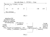
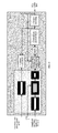
- FIG. 1 is a schematic diagram of a frame structure of an LTE system according to an embodiment of the present invention
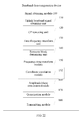
- FIG. 2 is a flow chart of generation of a baseband signal of an LTE PUSCH according to an embodiment of the present invention
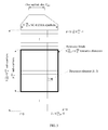
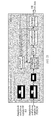
- FIG. 3 is a schematic diagram of an LTE uplink resource grid according to an embodiment of the present invention.
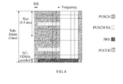
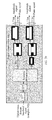
- FIG. 4 is a schematic diagram of distribution of various LTE uplink physical channels and reference signals in time and frequency domains according to an embodiment of the present invention
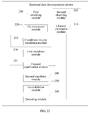
- FIG. 5 is a structural diagram of a baseband data compression device according to an embodiment of the present invention.
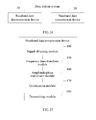
- FIG. 6 is a structural diagram of a baseband data decompression device according to an embodiment of the present invention.
- FIG. 7 is a structural diagram of a baseband data compression device according to an embodiment of the present invention.
- FIG. 8 is a structural diagram of a baseband data decompression device according to an embodiment of the present invention.
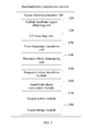
- FIG. 9 is a flow chart of an uplink baseband signal compression method according to an embodiment of the present invention.
- FIG. 10 is a flow chart of an uplink baseband signal compression method according to an embodiment of the present invention.
- FIG. 11 is a flow chart of an uplink baseband signal compression method according to an embodiment of the present invention.
- FIG. 12 is a flow chart of an uplink baseband signal decompression method according to an embodiment of the present invention.
- FIG. 13a is a flow chart of an uplink baseband signal decompression method according to an embodiment of the present invention.
- FIG. 13b is a flow chart of an uplink baseband signal decompression method according to an embodiment of the present invention.
- FIG. 14 is a superimposition schematic diagram of a 16QAM constellation according to an embodiment of the present invention.
- FIG. 15 shows a 16QAM constellation according to an embodiment of the present invention
- FIG. 16 is a diagram of constellation translation according to an embodiment of the present invention.
- FIG. 17 is a diagram of constellation translation according to an embodiment of the present invention.
- FIG. 18 is a schematic diagram of an uplink baseband signal compression method according to an embodiment of the present invention.
- FIG. 19 is a schematic diagram of an uplink baseband signal decompression method according to an embodiment of the present invention.
- FIG. 20 is a schematic diagram of an uplink baseband signal compression method according to an embodiment of the present invention.
- FIG. 21 is a schematic diagram of an uplink baseband signal decompression method according to an embodiment of the present invention.
- FIG. 22 is a structural diagram of a baseband data compression device according to an embodiment of the present invention.
- FIG. 23 is a structural diagram of a baseband data decompression device according to an embodiment of the present invention.
- FIG. 24 is a structural diagram of a base station system according to an embodiment of the present invention.
- FIG. 25 is a structural diagram of a baseband data compression device according to an embodiment of the present invention.
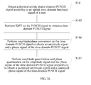
- FIG. 26 is a flow chart of an uplink baseband signal compression method according to an embodiment of the present invention.
- the OFDM (Orthogonal Frequency Division Multiplexing, orthogonal frequency division multiplexing) technology is a key technology in the LTE. Since an OFDM time-domain signal is a signal formed by superimposing several multi-carriers, a high PAPR (Peak to Average Power Ratio, peak to average power ratio) is caused. A relatively weak limitation is imposed on power at a base station side, and a relatively expensive power amplifier may be adopted, and therefore, influence of a high PAPR is not great in downlink. However, in uplink, being limited by the cost of a terminal, a high PAPR may have an extremely high requirement on a power amplifier of the terminal, which reduces power utilization of the terminal.
- OFDM Orthogonal Frequency Division Multiplexing, orthogonal frequency division multiplexing
- an SC-FDMA Single Carrier Frequency Division Multiple Access, single carrier frequency division multiple access modulation mode is adopted in LTE uplink.
- SC-FDMA Single Carrier Frequency Division Multiple Access, single carrier frequency division multiple access
- DFT Discrete Fourier transform, discrete Fourier transform
- IFFT Inverse Fast Fourier Transformation, inverse fast Fourier transformation
- FIG. 1 is a schematic diagram of a frame structure of an LTE system according to an embodiment of the present invention.
- a 10ms radio frame radio frame
- sub-frame sub-frame
- each sub-frame includes two slots (slot).
- LTE uplink signal processing is performed periodically at a certain transmission time interval (TTI, Transmission Time Interval), which is one sub-frame (sub-frame) in the LTE, and corresponds to time of 1 ms.
- TTI Transmission Time Interval
- An LTE uplink physical channel corresponds to a set of a series of REs, and is used for bearing information from a higher layer.
- the following uplink channels are defined: a physical uplink shared channel PUSCH (Physical Uplink Shared Channel), a physical uplink control channel PUCCH (Physical Uplink Control Channel), and a physical random access channel PRACH (Physical Random Access Channel).
- PUSCH Physical Uplink Shared Channel
- PUCCH Physical Uplink Control Channel
- PRACH Physical Random Access Channel
- an uplink physical signal is further defined, where the uplink physical signal refers to a signal that is used by a physical layer but does not bear any information from a higher layer, such as an uplink reference signal RS (Reference Signal).
- RS Reference Signal
- FIG. 2 is a flow chart of generation of a baseband signal of an LTE physical uplink shared channel (PUSCH) according to an embodiment of the present invention.
- uplink data of each user undergoes channel coding (including one or multiple kinds of the following: bit scrambling, CRC check sequence generation, channel coding, channel interleaving, and rate matching) and then undergoes constellation modulation mapping (including QPSK modulation, 16QAM modulation, or 64QAM modulation), where a data symbol sequence obtained after modulation is input to a DFT extension module to map a data stream to a frequency domain, resource mapping is performed on a frequency-domain data symbol sequence and a reference symbol (reference signal, RS) together, and data of different users is mapped to different orthogonal sub-carriers to achieve orthogonal frequency multiplexing among users; and then the signal is transformed to a time domain through IFFT, and a CP (Cyclic Prefix, cyclic prefix) is inserted
- channel coding including one or multiple kinds
- FIG. 3 is a schematic diagram of an LTE uplink resource grid according to an embodiment of the present invention.
- LTE uplink resource allocation is based on a resource block (RB: resource block), where one RB includes M consecutive SC-FDMA blocks in a time domain and N equivalent sub-carriers in a frequency domain.
- RB resource block
- air interface resources are categorized in the form of resource blocks, and as shown in FIG.
- a signal transmitted in one LTE uplink slot may be described by using one resource grid, one resource grid is formed by several resource blocks, and one resource block RB includes 12 sub-carriers in a frequency domain and 7 SC-FDMA blocks in a time domain in the case of normal CP configuration, and includes 12 sub-carriers in the frequency domain and 6 SC-FDMA blocks in the time domain in the case of extended CP configuration.
- a time/frequency resource allocated to each user is generally one logically virtual resource block (VRB), and a system then maps the VRB that is allocated to the user to a physical resource block PRB within a certain time/frequency range according to a predefined algorithm.
- VRB logically virtual resource block
- the system When allocating a resource to a user, the system specifies information such as type, number and size of a corresponding VRB resource, namely, VRB indication information, so that a corresponding sub-carrier actually occupied by the user in each OFDM symbol time can be obtained according to the predefined algorithm. Therefore, with resource block mapping and demapping described in the foregoing, user multiplexing and demultiplexing operations are completed, and specifically, resource block mapping is allocating a signal of each user to a corresponding sub-carrier, and resource block demapping is separating a signal of each user from a corresponding sub-carrier.
- VRBs are generally classified into two types: a localized (Localized) type and a distributed (Distributed) type, where a localized VRB corresponds to consecutive sub-carriers, which facilitates implementation of frequency selective scheduling and MIMO precoding; and a distributed VRB distributes sub-carriers of one user into a whole system bandwidth, so that a frequency diversity gain may be obtained, and the distributed VRB is generally used for transmitting a service with a small data amount such as VoIP (broadband telephony, Voice over Internet Protocol).
- VoIP broadband telephony, Voice over Internet Protocol
- the VRB is not only a minimum allocation unit of a resource occupied by a user, but is also a minimum configuration unit of a wireless transmission parameter of a physical layer, that is to say, no matter for the localized VRB or the distributed VRB, sub-carriers of a certain data stream of one user in one VRB always have the same code modulation mode and transmit power.
- a localized VRB is adopted in LTE uplink.
- An eNodeB may allocate a plurality of RBs to one UE, and notify the UE through uplink resource grant (Uplink Resource Grant) signaling.
- Uplink Resource Grant Uplink Resource Grant
- FIG. 4 is a schematic diagram of distribution of various LTE uplink physical channels and reference signals in time and frequency domains according to an embodiment of the present invention.
- a physical uplink control channel PUCCH is used for transmitting signaling such as CQI (channel quality indicator, channel quality indicator)/ACK (Acknowledgement, acknowledgement), and as shown in FIG. 4 , in a two-dimensional time-frequency plane, the PUCCH is fixed at the highest end and the lowest end of a user bandwidth, and is multiplexed with a data channel in a frequency division manner, and when no data is transmitted, a independent PUCCH does not adopt DFT extension, and PUCCH multiplexing of multiple users is performed in a code division manner (for example, code spreading). As shown in FIG.
- a physical uplink shared channel demodulation reference signal uses a constant amplitude zero auto-correlation (CAZAC) sequence, is multiplexed with the physical uplink shared channel in a time division manner, and is mainly used for solving uplink user data.
- CAZAC constant amplitude zero auto-correlation
- SRS uplink Sounding reference signal
- Distribution of the physical uplink shared channel PUSCH in the two-dimensional time-frequency plane is as shown in FIG. 4 , and the PUSCH may adopt QPSK, 16QAM or 64QAM modulation.
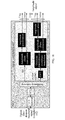
- an embodiment of the present invention provides a baseband data compression device, including:
- a signal obtaining module 100 may include an uplink baseband signal obtaining unit 110, a CP removing unit 120, a time-frequency transform unit 130, and a resource block demapping unit 140, and according to FIG. 5 , each unit and module are described as follows.
- the uplink baseband signal obtaining unit 110 is configured to obtain an uplink time-domain baseband signal of a user, where the uplink time-domain baseband signal of the user is a complex signal formed by I/Q components.
- the CP removing unit 120 is configured to remove a CP of the uplink time-domain baseband signal of the user to obtain a CP-removed uplink time-domain baseband signal.
- the time-frequency transform unit 130 is configured to perform FFT on the CP-removed uplink time-domain baseband signal to transform the CP-removed uplink time-domain baseband signal into an uplink frequency-domain baseband signal.
- the resource block demapping unit 140 is configured to perform resource block demapping on the uplink frequency-domain baseband signal to separate a PUSCH signal from the uplink frequency-domain baseband signal.
- resource block demapping may also be performed on the uplink frequency-domain baseband signal to separate a physical uplink control channel PUCCH, an uplink demodulation reference signal RS and an uplink Sounding reference signal from the uplink frequency-domain baseband signal.
- the frequency-time transform module 150 is configured to perform IDFT on the PUSCH signal to obtain a time-domain PUSCH signal.
- the amplitude/phase conversion module 160 is configured to perform amplitude/phase conversion on the time-domain PUSCH signal to obtain an amplitude signal and a phase signal of the time-domain PUSCH signal.
- the quantization module 170 is configured to perform amplitude quantization and phase quantization on the amplitude signal and the phase signal of the time-domain PUSCH signal respectively to obtain a quantized amplitude signal and a quantized phase signal of the time-domain PUSCH signal.
- the amplitude signal may be quantized by using a small number of bits, and the phase signal may be quantized by using an ordinary number of bits.
- a transmitting module 180 is configured to transmit the quantized amplitude signal and the quantized phase signal of the time-domain PUSCH signal.
- a physical uplink control channel PUCCH, an uplink reference signal RS and an uplink Sounding reference signal may also be separated from the uplink frequency-domain baseband signal. Since the uplink reference signal RS adopts a constant envelope sequence, compression processing may also be performed on the RS.
- the amplitude/phase conversion module 160 is further configured to perform amplitude/phase conversion on the RS to obtain an amplitude signal and a phase signal of the RS.
- the quantization module 170 is further configured to perform amplitude quantization and phase quantization on the amplitude signal and the phase signal of the RS respectively to obtain a quantized amplitude signal and a quantized phase signal of the RS.
- the transmitting module 180 is further configured to transmit the quantized amplitude signal and the quantized phase signal of the RS.
- the RRU may further include:
- the baseband data compression device may be deployed on the RRU.
- IDFT is performed on a PUSCH signal that is obtained after resource block demapping; due to a characteristic of an extremely low peak to average power ratio of SC-FDMA modulation adopted by an LTE system, a signal after IDFT has an extremely low peak to average power ratio at this time, and an amplitude range of the signal changes slightly; amplitude/phase conversion is performed on the signal after the IDFT, where the signal after the IDFT is represented by using amplitude and phase, and then amplitude quantization and phase quantization are performed respectively to obtain a quantized amplitude signal and a quantized phase signal respectively, so that a baseband signal can be compressed efficiently.
- an embodiment of the present invention provides a baseband data decompression device, including:
- a first obtaining module 210 is configured to obtain a quantized amplitude signal and a quantized phase signal of a time-domain PUSCH signal.
- the quantized amplitude signal and the quantized phase signal of the time-domain PUSCH signal are transmitted from a baseband data compression device on an RRU in one embodiment.
- An I/Q conversion module 220 is configured to perform I/Q conversion on the quantized amplitude signal and the quantized phase signal of the time-domain PUSCH signal to obtain a complex PUSCH signal, where the complex PUSCH signal is a complex signal formed by I/Q components.
- a first transform module 230 is configured to perform DFT on the complex PUSCH signal to map the complex PUSH signal to a frequency domain.
- a second transform module 240 is configured to perform IDFT on the PUSCH signal that undergoes the DFT, to obtain a time-domain PUSCH signal;
- a demodulation module 250 is configured to perform constellation demodulation on the time-domain PUSCH signal to obtain demodulated data.
- a decoding module 260 is configured to perform channel decoding on the demodulated data to obtain uplink data of a user.
- the baseband data decompression device may be deployed on a BBU.
- compression processing is performed on a signal at an RRU side, where according to the method provided in this embodiment of the present invention, IDFT is performed on a PUSCH signal that is obtained after resource block demapping; due to a characteristic of an extremely low peak to average power ratio of SC-FDMA modulation adopted by an LTE system, a signal after IDFT has an extremely low peak to average power ratio at this time, and an amplitude range of the signal changes slightly; amplitude/phase conversion is performed on the signal after the IDFT, where the signal after the IDFT is represented by using amplitude and phase, and then amplitude quantization and phase quantization are performed respectively to obtain a quantized amplitude signal and a quantized phase signal respectively, so that a baseband signal can be compressed efficiently; and corresponding decompression processing is adopted at a BBU side to recover data of a user, so that a transmission bandwidth of a baseband signal can be greatly reduced, thereby improving utilization efficiency of
- the baseband data compression device may include:
- An uplink baseband signal obtaining unit 110 is configured to obtain an uplink time-domain baseband signal of a user, where the uplink time-domain baseband signal of the user is a complex signal formed by I/Q components.
- a CP removing unit 120 is configured to remove a CP of the uplink time-domain baseband signal of the user to obtain a CP-removed uplink time-domain baseband signal.
- a time-frequency transform unit 130 is configured to perform FFT on the CP-removed uplink time-domain baseband signal to transform the CP-removed uplink time-domain baseband signal into an uplink frequency-domain baseband signal.
- a resource block demapping unit 140 is configured to perform resource block demapping on the uplink frequency-domain baseband signal to separate a PUSCH signal and an RS from the uplink frequency-domain baseband signal.
- An RS channel estimation module 141 is configured to perform channel estimation on the RS to obtain an estimated channel of the RS.
- An MIMO detection module 142 is configured to perform MIMO detection on the PUSCH signal according to the estimated channel of the RS to obtain a MIMO-detected PUSCH signal, where the estimated channel of the RS is obtained by the RS channel estimation module.
- a frequency-time transform module 150 is configured to perform IDFT on the MIMO-detected PUSCH signal to obtain a time-domain PUSCH signal.
- An amplitude/phase conversion module 160 is configured to perform amplitude/phase conversion on the time-domain PUSCH signal to obtain an amplitude signal and a phase signal of the time-domain PUSCH signal; and perform amplitude/phase conversion on the RS to obtain an amplitude signal and a phase signal of the RS.
- a quantization module 170 is configured to perform amplitude quantization and phase quantization on the amplitude signal and the phase signal of the time-domain PUSCH signal respectively to obtain a quantized amplitude signal and a quantized phase signal of the time-domain PUSCH signal; and perform amplitude quantization and phase quantization on the amplitude signal and the phase signal of the RS respectively to obtain a quantized amplitude signal and a quantized phase signal of the RS.
- the amplitude signal may be quantized by using a small number of bits, and the phase signal may be quantized by using an ordinary number of bits.
- a transmitting module 180 is configured to transmit the quantized amplitude signal and the quantized phase signal of the time-domain PUSCH signal, and the quantized amplitude signal and the quantized phase signal of the RS.
- an amplitude signal of a PUSCH signal may be quantized by using 7 bits, and a phase signal of the PUSCH signal may be quantized by using 14 bits, to perform compression processing; and an amplitude signal of an RS may be quantized by using 7 bits, and a phase signal of the RS may be quantized by using 14 bits.
- the amplitude signal of the PUSCH signal may be quantized and compressed by using 9 bits, and the phase signal of the PUSCH signal may be quantized and compressed by using 14 bits; and the amplitude signal of the RS may be quantized by using 7 bits, and the phase signal of the RS may be quantized by using 14 bits.
- the amplitude signal of the PUSCH signal may be quantized and compressed by using 11 bits, and the phase signal of the PUSCH signal may be quantized and compressed by using 14 bits; and the amplitude signal of the RS may be quantized by using 7 bits, and the phase signal of the RS may be quantized by using 14 bits.
- An average compression ratio is 20%, so that a transmission bandwidth of a baseband signal can be greatly reduced.
- IDFT is performed on a PUSCH signal that is obtained after resource block demapping; due to a characteristic of an extremely low peak to average power ratio of SC-FDMA modulation adopted by an LTE system, a signal after IDFT has an extremely low peak to average power ratio at this time, and an amplitude range of the signal changes slightly; amplitude/phase conversion is performed on the signal after the IDFT, where the signal after the IDFT is represented by using amplitude and phase, and then amplitude quantization and phase quantization are performed respectively to obtain a quantized amplitude signal and a quantized phase signal respectively, so that a baseband signal can be compressed efficiently.
- an advanced receiver algorithm such as a Turbo iterative receiver or an MIMO SIC receiver
- a baseband data decompression device may flexibly adopt various advanced receiver algorithms.
- an embodiment of the present invention provides a baseband data decompression device, including:
- a first obtaining module 210 is configured to obtain a quantized amplitude signal and a quantized phase signal of a time-domain PUSCH signal.
- a second obtaining module 212 is configured to obtain a quantized amplitude signal and a quantized phase signal of an RS.
- a channel estimation module 214 is configured to perform channel estimation on the quantized amplitude signal and the quantized phase signal of the RS to obtain an estimated signal, where the quantized amplitude signal and the quantized phase signal of the RS are received by the second obtaining module 212.
- the quantized amplitude signal and the quantized phase signal of the time-domain PUSCH signal are transmitted from an RRU in one embodiment.
- An I/Q conversion module 220 is configured to perform I/Q conversion on the quantized amplitude signal and the quantized phase signal of the time-domain PUSCH signal to obtain a complex PUSCH signal, where the complex PUSCH signal is a complex signal formed by I/Q components.
- a first transform module 230 is configured to perform DFT on the complex PUSCH signal to map the complex PUSH signal to a frequency domain.
- a channel equalization module 231 is configured to perform, by using the estimated signal, channel equalization on the PUSCH signal that undergoes the DFT, to obtain a channel equalized PUSCH signal.
- a second transform module 240 is configured to perform IDFT on the channel equalized PUSCH signal to obtain a time-domain PUSCH signal.
- a demodulation module 250 is configured to perform constellation demodulation on the time-domain PUSCH signal to obtain demodulated data.
- a decoding module 260 is configured to perform channel decoding on the demodulated data to obtain uplink data of a user.
- the I/Q conversion module 220 is further configured to perform I/Q conversion on the quantized amplitude signal and the quantized phase signal of the RS to obtain a complex RS, where the complex RS is a complex signal formed by I/Q components; and accordingly, the channel estimation module 214 is specifically configured to perform channel estimation on the complex RS to obtain an estimated signal.
- the demodulated data may be fed back to the channel estimation module 214, where the demodulated data is obtained after the demodulation module 250 performs constellation demodulation on the time-domain PUSCH signal, to assist the channel estimation module 214 to perform channel estimation; and in one embodiment, to further improve the system performance, the demodulated data may also be fed back to the channel equalization module 231, where the demodulated data is obtained after the demodulation module 250 performs constellation demodulation on the time-domain PUSCH signal, to assist the channel equalization module 231 to perform channel equalization.
- the uplink data of the user may be fed back to the channel estimation module 214, where the uplink data of the user is obtained by the decoding module 260, to assist the channel estimation module 214 to perform channel estimation; and in one embodiment, to further improve the system performance, the uplink data of the user may also be fed back to the channel equalization module 231, where the uplink data of the user is obtained by the decoding module 260, to assist the channel equalization module 231 to perform channel equalization.
- the baseband data decompression device may further include:
- compression processing is performed on a signal at an RRU side, where according to the method provided in this embodiment of the present invention, IDFT is performed on a PUSCH signal that is obtained after resource block demapping; due to a characteristic of an extremely low peak to average power ratio of SC-FDMA modulation adopted by an LTE system, a signal after IDFT has an extremely low peak to average power ratio at this time, and an amplitude range of the signal changes slightly; amplitude/phase conversion is performed on the signal after the IDFT, where the signal after the IDFT is represented by using amplitude and phase, and then amplitude quantization and phase quantization are performed respectively to obtain a quantized amplitude signal and a quantized phase signal respectively, so that a baseband signal can be compressed efficiently; and corresponding decompression processing is adopted at a BBU side to recover data of a user, so that a transmission bandwidth of a baseband signal can be greatly reduced, thereby improving utilization efficiency of
- an embodiment of the present invention further provides a structural diagram of a base station system, where the base station system includes a baseband data compression device 20 and a baseband data decompression device 30.
- the base station system includes a baseband data compression device 20 and a baseband data decompression device 30.
- Specific structures and functions of the baseband data compression device 20 and the baseband data decompression device 30 have been described in detail in the foregoing embodiments, which are not described here again.
- compression processing is performed on a signal at an RRU side, where according to the method provided in this embodiment of the present invention, IDFT is performed on a PUSCH signal that is obtained after resource block demapping; due to a characteristic of an extremely low peak to average power ratio of SC-FDMA modulation adopted by an LTE system, a signal after IDFT has an extremely low peak to average power ratio at this time, and an amplitude range of the signal changes slightly; amplitude/phase conversion is performed on the signal after the IDFT, where the signal after the IDFT is represented by using amplitude and phase, and then amplitude quantization and phase quantization are performed respectively to obtain a quantized amplitude signal and a quantized phase signal respectively, so that a baseband signal can be compressed efficiently; and corresponding decompression processing is adopted at a BBU side to recover data of a user, so that a transmission bandwidth of a baseband signal can be greatly reduced, thereby improving utilization efficiency of
- an embodiment of the present invention provides an uplink baseband signal compression method.
- the method includes:
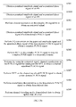
- S10 Obtain a physical uplink shared channel PUSCH signal according to an uplink time-domain baseband signal of a user.
- S105 Perform inverse discrete Fourier transform IDFT on the PUSCH signal to obtain a time-domain PUSCH signal.
- S106 Perform amplitude/phase conversion on the time-domain PUSCH signal to obtain an amplitude signal and a phase signal of the time-domain PUSCH signal.
- S107 Perform amplitude quantization and phase quantization on the amplitude signal and the phase signal of the time-domain PUSCH signal respectively to obtain a quantized amplitude signal and a quantized phase signal of the time-domain PUSCH signal.
- compression processing is performed on a signal at an RRU side, where according to the method provided in this embodiment of the present invention, IDFT is performed on a PUSCH signal that is obtained after resource block demapping; due to a characteristic of an extremely low peak to average power ratio of SC-FDMA modulation, a signal after IDFT has an extremely low peak to average power ratio at this time, and an amplitude range of the signal changes slightly; amplitude/phase conversion is performed on the signal after the IDFT, where the signal after the IDFT is represented by using amplitude and phase, and then amplitude quantization and phase quantization are performed respectively to obtain a quantized amplitude signal and a quantized phase signal respectively, so that a baseband signal can be compressed efficiently; and corresponding decompression processing is adopted at a BBU side to recover data of a user, so that a transmission bandwidth of a baseband signal can be greatly reduced, thereby improving utilization efficiency of a resource.
- an embodiment of the present invention provides an uplink baseband signal compression method.
- the method includes:
- S101 Obtain an uplink time-domain baseband signal of a user, where the uplink time-domain baseband signal of the user is a complex signal formed by I/Q components.
- S102 Remove a CP of the uplink time-domain baseband signal of the user to obtain a CP-removed uplink time-domain baseband signal.
- S103 Perform FFT on the CP-removed uplink time-domain baseband signal to transform the CP-removed uplink time-domain baseband signal into an uplink frequency-domain baseband signal.
- S104 Perform resource block demapping on the uplink frequency-domain baseband signal to separate a PUSCH signal from the uplink frequency-domain baseband signal.
- resource block demapping may also be performed on the uplink frequency-domain baseband signal to separate a physical uplink control channel PUCCH, an uplink demodulation reference signal RS and an uplink Sounding reference signal from the uplink frequency-domain baseband signal.
- S 105 Perform IDFT on the PUSCH signal to obtain a time-domain PUSCH signal.
- S106 Perform amplitude/phase conversion on the time-domain PUSCH signal to obtain an amplitude signal and a phase signal of the time-domain PUSCH signal.
- S107 Perform amplitude quantization and phase quantization on the amplitude signal and the phase signal of the time-domain PUSCH signal respectively to obtain a quantized amplitude signal and a quantized phase signal of the time-domain PUSCH signal.
- the amplitude signal may be quantized by using a small number of bits, and the phase signal may be quantized by using an ordinary number of bits.
- S108 Transmit the quantized amplitude signal and the quantized phase signal of the time-domain PUSCH signal.
- IDFT is performed on a PUSCH signal that is obtained after resource block demapping; due to a characteristic of an extremely low peak to average power ratio of SC-FDMA modulation adopted by an LTE system, a signal after IDFT has an extremely low peak to average power ratio at this time, and an amplitude range of the signal changes slightly; amplitude/phase conversion is performed on the signal after the IDFT, where the signal after the IDFT is represented by using amplitude and phase, and then amplitude quantization and phase quantization are performed respectively to obtain a quantized amplitude signal and a quantized phase signal respectively, so that a baseband signal can be compressed efficiently.
- a physical uplink control channel PUCCH, an uplink reference signal RS, and an uplink Sounding reference signal may also be separated from the uplink frequency-domain baseband signal. Since the uplink reference signal RS adopts a constant envelope sequence, compression processing may also be performed on the RS.
- an LTE uplink baseband signal compression method includes:
- S201 Obtain an uplink time-domain baseband signal of a user, where the uplink time-domain baseband signal of the user is a complex signal formed by I/Q components.
- S202 Remove a CP of the uplink time-domain baseband signal of the user to obtain a CP-removed uplink time-domain baseband signal.
- S203 Perform FFT on the CP-removed uplink time-domain baseband signal to transform the CP-removed uplink time-domain baseband signal into an uplink frequency-domain baseband signal.
- S204 Perform resource block demapping on the uplink frequency-domain baseband signal to separate a PUSCH signal and an RS from the uplink frequency-domain baseband signal.
- resource block demapping may also be performed on the uplink frequency-domain baseband signal to separate an uplink Sounding reference signal from the uplink frequency-domain baseband signal.
- S205 Perform amplitude/phase conversion on the RS that is obtained through separation, to obtain an amplitude signal and a phase signal of the RS.
- S206 Perform IDFT on the PUSCH signal to obtain a time-domain PUSCH signal.
- S207 Perform amplitude/phase conversion on the time-domain PUSCH signal to obtain an amplitude signal and a phase signal of the time-domain PUSCH signal.
- S208 Perform amplitude quantization and phase quantization on the amplitude signal and the phase signal of the time-domain PUSCH signal respectively to obtain a quantized amplitude signal and a quantized phase signal of the time-domain PUSCH signal; and perform amplitude quantization and phase quantization on the amplitude signal and the phase signal of the RS respectively to obtain a quantized amplitude signal and a quantized phase signal of the RS.
- the amplitude signal may be quantized by using a small number of bits, and the phase signal may be quantized by using an ordinary number of bits.
- S209 Transmit the quantized amplitude signal and the quantized phase signal of the time-domain PUSCH signal and the quantized amplitude signal and the quantized phase signal of the RS.
- the following step may further be included before S207:
- MIMO transmission or virtual MIMO transmission may be adopted in uplink, and at this time, as shown in FIG. 11 , an embodiment of the present invention provides an LTE uplink baseband signal compression method.
- the method includes:
- S301 Obtain an uplink time-domain baseband signal of a user, where the uplink time-domain baseband signal of the user is a complex signal formed by I/Q components.
- S302 Remove a CP of the uplink time-domain baseband signal of the user to obtain a CP-removed uplink time-domain baseband signal.
- S303 Perform FFT on the CP-removed uplink time-domain baseband signal to transform the CP-removed uplink time-domain baseband signal into an uplink frequency-domain baseband signal.
- S304 Perform resource block demapping on the uplink frequency-domain baseband signal to separate a PUSCH signal and an RS from the uplink frequency-domain baseband signal.
- resource block demapping may also be performed on the uplink frequency-domain baseband signal to separate an uplink Sounding reference signal from the uplink frequency-domain baseband signal.
- S305 Perform channel estimation on the RS to obtain an estimated channel of the RS.
- S306 Perform MIMO detection on the PUSCH signal according to the estimated channel of the RS to obtain a MIMO-detected PUSCH signal.
- S307 Perform IDFT on the MIMO-detected PUSCH signal to obtain a time-domain PUSCH signal.
- S308 Perform amplitude/phase conversion on the time-domain PUSCH signal to obtain an amplitude signal and a phase signal of the time-domain PUSCH signal.
- S309 Perform amplitude/phase conversion on the RS that is obtained through separation, to obtain an amplitude signal and a phase signal of the RS.
- S310 Perform amplitude quantization and phase quantization on the amplitude signal and the phase signal of the time-domain PUSCH signal respectively to obtain a quantized amplitude signal and a quantized phase signal of the time-domain PUSCH signal; and perform amplitude quantization and phase quantization on the amplitude signal and the phase signal of the RS respectively to obtain a quantized amplitude signal and a quantized phase signal of the RS.
- the amplitude signal may be quantized by using a small number of bits, and the phase signal may be quantized by using an ordinary number of bits.
- S311 Transmit the quantized amplitude signal and the quantized phase signal of the time-domain PUSCH signal and the quantized amplitude signal and the quantized phase signal of the RS.
- an amplitude signal of a PUSCH signal may be quantized by using 7 bits, and a phase signal of the PUSCH signal may be quantized by using 14 bits, to perform compression processing; and an amplitude signal of an RS may be quantized by using 7 bits, and a phase signal of the RS may be quantized by using 14 bits.
- the amplitude signal of the PUSCH signal may be quantized and compressed by using 9 bits, and the phase signal of the PUSCH signal may be quantized and compressed by using 14 bits; and the amplitude signal of the RS may be quantized by using 7 bits, and the phase signal of the RS may be quantized by using 14 bits.
- the amplitude signal of the PUSCH signal may be quantized and compressed by using 11 bits, and the phase signal of the PUSCH signal may be quantized and compressed by using 14 bits; and the amplitude signal of the RS may be quantized by using 7 bits, and the phase signal of the RS may be quantized by using 14 bits.
- An average compression ratio is 20%, so that a transmission bandwidth of a baseband signal can be greatly reduced.
- an embodiment of the present invention provides an LTE uplink baseband signal decompression method, where the method includes:
- S401 Obtain a quantized amplitude signal and a quantized phase signal of a time-domain PUSCH signal.
- the quantized amplitude signal and the quantized phase signal of the time-domain PUSCH signal are transmitted from an RRU in one embodiment.
- S402 Perform I/Q conversion on the quantized amplitude signal and the quantized phase signal of the time-domain PUSCH signal to obtain a complex PUSCH signal, where the complex PUSCH signal is a complex signal formed by I/Q components.
- S403 Perform DFT on the complex PUSCH signal to map the complex PUSH signal to a frequency domain.
- S404 Perform IDFT on the PUSCH signal that undergoes the DFT, to obtain a time-domain PUSCH signal.
- S405 Perform constellation demodulation on the time-domain PUSCH signal to obtain demodulated data.
- S406 Perform channel decoding on the demodulated data to obtain uplink data of a user.
- compression processing is performed on a signal at an RRU side, where according to the method provided in this embodiment of the present invention, IDFT is performed on a PUSCH signal that is obtained after resource block demapping; due to a characteristic of an extremely low peak to average power ratio of SC-FDMA modulation adopted by an LTE system, a signal after IDFT has an extremely low peak to average power ratio at this time, and an amplitude range of the signal changes slightly; amplitude/phase conversion is performed on the signal after the IDFT, where the signal after the IDFT is represented by using amplitude and phase, and then amplitude quantization and phase quantization are performed respectively to obtain a quantized amplitude signal and a quantized phase signal respectively, so that a baseband signal can be compressed efficiently; and corresponding decompression processing is adopted at a BBU side to recover data of a user, so that a transmission bandwidth of a baseband signal can be greatly reduced, thereby improving utilization efficiency of
- an advanced receiver algorithm such as a Turbo iterative receiver or an MIMO SIC receiver, may be adopted at a BBU side.
- a BBU provided in this embodiment of the present invention may flexibly adopt various advanced receiver algorithms.
- an embodiment of the present invention provides an LTE uplink baseband signal decompression method, where the method includes:
- S501 Obtain a quantized amplitude signal and a quantized phase signal of an RS.
- S502 Perform channel estimation on the quantized amplitude signal and the quantized phase signal of the RS to obtain an estimated signal.
- S503 Obtain a quantized amplitude signal and a quantized phase signal of a time-domain PUSCH signal.
- the quantized amplitude signal and the quantized phase signal of the time-domain PUSCH signal are transmitted from an RRU in one embodiment.
- S504 Perform I/Q conversion on the quantized amplitude signal and the quantized phase signal of the time-domain PUSCH signal to obtain a complex PUSCH signal, where the complex PUSCH signal is a complex signal formed by I/Q components.
- S505 Perform DFT on the complex PUSCH signal to map the complex PUSH signal to a frequency domain.
- S506 Perform, by using the estimated signal, channel equalization on the PUSCH signal that undergoes the DFT, to obtain a channel equalized PUSCH signal.
- S507 Perform IDFT on the channel equalized PUSCH signal to obtain a time-domain PUSCH signal.
- S508 Perform constellation demodulation on the time-domain PUSCH signal to obtain demodulated data.
- S509 Perform channel decoding on the demodulated data to obtain uplink data of a user.
- the method further includes:
- S5020 Perform I/Q conversion on the quantized amplitude signal and the quantized phase signal of the RS to obtain a complex RS, where the complex RS is a complex signal formed by I/Q components.
- Step S502 specifically includes: performing channel estimation on the complex RS to obtain an estimated signal.
- data obtained after constellation demodulation in S508 or data obtained after channel decoding in S509 may be fed back to assist channel estimation in S502 or S5020 or channel equalization in S506.
- the method may further include the following step:
- compression processing is performed on a signal at an RRU side, where according to the method provided in this embodiment of the present invention, IDFT is performed on a PUSCH signal that is obtained after resource block demapping; due to a characteristic of an extremely low peak to average power ratio of SC-FDMA modulation adopted by an LTE system, a signal after IDFT has an extremely low peak to average power ratio at this time, and an amplitude range of the signal changes slightly; amplitude/phase conversion is performed on the signal after the IDFT, where the signal is represented by using amplitude and phase, and then amplitude quantization and phase quantization are performed respectively to obtain a quantized amplitude signal and a quantized phase signal respectively, so that a baseband signal can be compressed efficiently; and corresponding decompression processing is adopted at a BBU side to recover data of a user, so that a transmission bandwidth of a baseband signal can be greatly reduced, thereby improving utilization efficiency of a resource.
- QPSK modulation symbols x I + jQ, as shown in Table 1: Table 1 QPSK modulation mapping table b(i), b(i + 1) I Q 00 1 / 2 1 / 2 01 1 / 2 - 1 / 2 10 - 1 / 2 1 / 2 11 - 1 / 2 - 1 / 2
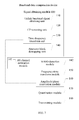
- QPSK modulation symbols are four points on a unit circle, characterized by having the same amplitude, and therefore, when the PUSCH adopts QPSK modulation, a processing method shown in FIG. 20 is adopted.
- the RRU After receiving an uplink time-domain baseband signal (the uplink time-domain baseband signal is a complex signal formed by I/Q components), the RRU removes a cyclic prefix CP, performs FFT to transform the signal to a frequency domain, and performs resource block demapping on a frequency-domain signal to separate a reference signal RS and a PUSCH signal.
- the uplink time-domain baseband signal is a complex signal formed by I/Q components
- Amplitude/phase conversion is performed on the reference signal RS to obtain an amplitude signal and a phase signal of the RS (that is, amplitude and phase of the RS), the amplitude signal of the RS is quantized by using 7 bits to obtain a quantized amplitude signal of the RS, and the phase signal of the RS is quantized by using 14 bits to obtain a quantized phase signal of the RS.
- IDFT transform is performed on the PUSCH signal after resource block demapping to obtain a time-domain PUSCH signal
- amplitude/phase conversion is performed on the time-domain PUSCH signal to obtain an amplitude signal and a phase signal of the time-domain PUSCH signal (that is, amplitude and phase of the PUSCH)
- the amplitude signal of the time-domain PUSCH signal is quantized by using 7 bits to obtain a quantized amplitude signal of the time-domain PUSCH signal
- the phase signal of the time-domain PUSCH signal is quantized by using 14 bits to obtain a quantized phase signal of the time-domain PUSCH signal.
- the BBU receives amplitude and phase signals of the RS (that is, the quantized amplitude signal of the RS and the quantized phase signal of the RS) and amplitude and phase signals of the PUSCH (that is, the quantized amplitude signal of the time-domain PUSCH signal and the quantized phase signal of the time-domain PUSCH signal) from the RRU, a processing procedure of which is shown in FIG. 21 .
- I/Q conversion is performed on the quantized amplitude signal and the quantized phase signal of the RS to obtain a complex RS
- the complex RS is a complex signal formed by I/Q components, that is, an RS I/Q complex signal
- channel estimation is performed by using the signal
- I/Q conversion is performed on the amplitude and phase signals of the PUSCH to obtain a complex PUSCH signal
- the complex PUSCH signal is a complex signal formed by I/Q components, also called PUSCH I/Q complex signal
- DFT transform is performed
- channel equalization processing is performed by using a channel, where the channel is obtained through estimation by using the RS
- IDFT transform constellation demodulation and channel decoding are performed on channel equalized data to obtain uplink data of a user.
- data obtained after constellation demodulation or data obtained after channel decoding may be fed back to assist channel estimation or channel equalization.
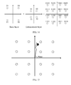
- 16QAM may be represented as superimposition of two QPSK (first QPSK and second QPSK), as shown in a superimposition schematic diagram of a 16QAM constellation provided in FIG. 14 .
- the first QPSK represents a quadrant (a basic layer in FIG. 14 ) where a constellation point is located
- the second QPSK an enhancement layer in FIG. 14
- an embodiment of the present invention provides a compression method for 16QAM, as shown in FIG. 18 .
- the RRU After receiving an uplink time-domain baseband signal (the uplink time-domain baseband signal is a complex signal formed by I/Q components), the RRU removes a cyclic prefix CP, performs FFT to transform the signal to a frequency domain, and performs resource block demapping on a frequency-domain signal to separate a reference signal RS and a PUSCH signal.
- the uplink time-domain baseband signal is a complex signal formed by I/Q components
- Amplitude/phase conversion is performed on the reference signal RS to obtain an amplitude signal and a phase signal of the RS (that is, amplitude and phase of the RS), the amplitude signal of the RS is quantized by using 7 bits to obtain a quantized amplitude signal of the RS, and the phase signal of the RS is quantized by using 14 bits to obtain a quantized phase signal of the RS.
- IDFT transform is performed on the PUSCH signal after resource block demapping to obtain a time-domain PUSCH signal
- the time-domain PUSCH signal is an I/Q signal modulated by adopting 16QAM
- a quadrant of the time-domain PUSCH signal is represented by using 2 bits
- coordinate translation is performed according to the quadrant
- amplitude/phase conversion is performed on the signal after constellation translation to obtain an amplitude signal and a phase signal of the time-domain PUSCH signal (that is, amplitude and phase of the PUSCH)
- the amplitude signal of the time-domain PUSCH signal is quantized by using 7 bits to obtain a quantized amplitude signal of the time-domain PUSCH signal
- the phase signal of the time-domain PUSCH signal is quantized by using 14 bits to obtain a quantized phase signal of the time-domain PUSCH signal.
- white circles represent constellation points of 16QAM modulation
- a black circle represents a position of a received signal in a 16QAM constellation, where this point is connected to origin of coordinates, and may be represented by amplitude and phase.
- this point is in a first quadrant, and then coordinates are translated to the first quadrant, where as shown in FIG. 16 , at new coordinates, constellation points in the first quadrant are similar to QPSK, amplitude/phase conversion is performed on the signal after constellation translation according to the new coordinates, where the signal after constellation translation is represented by using new amplitude and phase, the new amplitude is quantized by using 7 bits to obtain a quantized amplitude signal of the PUSCH (that is, the amplitude signal of the time-domain PUSCH signal), and the new phase after coordinate translation is quantized by using 14 bits to obtain a quantized phase signal of the PUSCH (the phase signal of the time-domain PUSCH signal).
- the BBU receives amplitude and phase signals of the RS and amplitude and phase signals of the PUSCH from the RRU, and a 16QAM constellation point quadrant signal that is represented by using 2 bits, a processing procedure of which is shown in FIG. 19 .
- compression processing is performed on a signal at an RRU side, where according to the method provided in this embodiment of the present invention, IDFT is performed on a PUSCH signal that is obtained after resource block demapping; due to a characteristic of an extremely low peak to average power ratio of SC-FDMA modulation adopted by an LTE system, a signal after IDFT has an extremely low peak to average power ratio at this time, and an amplitude range of the signal changes slightly; amplitude/phase conversion is performed on the signal after the IDFT, where the signal after the IDFT is represented by using amplitude and phase, and then amplitude quantization and phase quantization are performed respectively to obtain a quantized amplitude signal and a quantized phase signal respectively, so that a baseband signal can be compressed efficiently; and corresponding decompression processing is adopted at a BBU side to recover data of a user, so that a transmission bandwidth of a baseband signal can be greatly reduced, thereby improving utilization efficiency of
- the program may be stored in a computer-readable storage medium.
- the storage medium may be a magnetic disk, an optical disk, a Read-Only Memory (Read-Only Memory, ROM), a Random Access Memory (Random Access Memory, RAM), or the like.
Landscapes
- Engineering & Computer Science (AREA)
- Physics & Mathematics (AREA)
- Discrete Mathematics (AREA)
- General Physics & Mathematics (AREA)
- Mathematical Physics (AREA)
- Computer Networks & Wireless Communication (AREA)
- Signal Processing (AREA)
- Theoretical Computer Science (AREA)
- Mobile Radio Communication Systems (AREA)
- Digital Transmission Methods That Use Modulated Carrier Waves (AREA)
- Reduction Or Emphasis Of Bandwidth Of Signals (AREA)
Applications Claiming Priority (1)
| Application Number | Priority Date | Filing Date | Title |
|---|---|---|---|
| PCT/CN2011/080396 WO2013044492A1 (fr) | 2011-09-30 | 2011-09-30 | Procédé de compression de signal en bande de base de liaison montante, procédé de décompression, dispositif et système |
Publications (3)
| Publication Number | Publication Date |
|---|---|
| EP2590375A1 true EP2590375A1 (fr) | 2013-05-08 |
| EP2590375A4 EP2590375A4 (fr) | 2013-05-08 |
| EP2590375B1 EP2590375B1 (fr) | 2015-08-26 |
Family
ID=47501766
Family Applications (1)
| Application Number | Title | Priority Date | Filing Date |
|---|---|---|---|
| EP11860105.3A Active EP2590375B1 (fr) | 2011-09-30 | 2011-09-30 | Méthode de compression et de décompression d'un signal montant en bande de base ainsi qu' appareil et système correspondants |
Country Status (4)
| Country | Link |
|---|---|
| US (1) | US8542573B2 (fr) |
| EP (1) | EP2590375B1 (fr) |
| CN (1) | CN103348645B (fr) |
| WO (1) | WO2013044492A1 (fr) |
Cited By (1)
| Publication number | Priority date | Publication date | Assignee | Title |
|---|---|---|---|---|
| EP2911360A1 (fr) * | 2014-02-21 | 2015-08-26 | Mobile Techno Corp. | Dispositif de compression de signal numérique complexe, procédé et support de stockage lisible par ordinateur, dispositif de dilatation d'un signal numérique complexe, procédé et support de stockage lisible par ordinateur, et dispositif de communication |
Families Citing this family (29)
| Publication number | Priority date | Publication date | Assignee | Title |
|---|---|---|---|---|
| US8914052B2 (en) * | 2011-01-20 | 2014-12-16 | Telefonaktiebolaget Lm Ericsson (Publ) | Backhaul signal compression through spatial-temporal linear prediction |
| US9559806B2 (en) * | 2012-12-04 | 2017-01-31 | Dali Systems Co. Ltd. | Power amplifier protection using a cyclic redundancy check on the digital transport of data |
| US9936470B2 (en) | 2013-02-07 | 2018-04-03 | Commscope Technologies Llc | Radio access networks |
| US9414399B2 (en) | 2013-02-07 | 2016-08-09 | Commscope Technologies Llc | Radio access networks |
| US9380466B2 (en) | 2013-02-07 | 2016-06-28 | Commscope Technologies Llc | Radio access networks |
| CN104378117B (zh) * | 2013-08-15 | 2017-11-14 | 京信通信系统(中国)有限公司 | 数据压缩方法及装置、数据传输方法及系统 |
| US20150117866A1 (en) * | 2013-10-31 | 2015-04-30 | Zte Corporation | Quadrature amplitude modulation symbol mapping |
| US9635529B2 (en) | 2014-06-05 | 2017-04-25 | Empire Technology Development Llc | PAPR adjustment using precoder data |
| CN106664745B (zh) * | 2014-06-23 | 2020-03-03 | 意大利电信股份公司 | 用于减少集中式无线电接入网络(c-ran)中前传负载的方法 |
| BR112017002566A2 (pt) | 2014-09-10 | 2017-12-05 | Intel Ip Corp | cabeça de rádio remota melhorada (errh) e dispositivo para alcançar compactação de front-haul em uma rede de acesso de rádio com base em nuvem (c-ran) |
| WO2016191987A1 (fr) * | 2015-05-29 | 2016-12-08 | 华为技术有限公司 | Procédé, appareil et système d'émission de signal i/q |
| EP3348083B1 (fr) * | 2015-09-10 | 2020-06-10 | INTEL Corporation | Procédés de traitement de signaux, appareil et station de base |
| CN108352897B (zh) * | 2015-12-17 | 2020-02-21 | 华为技术有限公司 | 一种侦听参考符号传输方法及射频拉远单元 |
| US10135599B2 (en) * | 2016-08-05 | 2018-11-20 | Nokia Technologies Oy | Frequency domain compression for fronthaul interface |
| CN109565332A (zh) * | 2016-08-10 | 2019-04-02 | 联想创新有限公司(香港) | 定时提前调整通信 |
| US10257105B2 (en) * | 2016-12-02 | 2019-04-09 | At&T Intellectual Property I, L.P. | Facilitation of physical layer design for 5G networks or other next generation networks |
| GB2558586A (en) * | 2017-01-06 | 2018-07-18 | Tcl Communication Ltd | Resource block waveform transmission structures for uplink communications |
| CN108429713B (zh) * | 2017-02-13 | 2020-06-16 | 大唐移动通信设备有限公司 | 一种数据压缩方法及装置 |
| CN106992786B (zh) * | 2017-03-21 | 2020-07-07 | 深圳三星通信技术研究有限公司 | 一种基带数据压缩方法、装置和系统 |
| CN107729288B (zh) * | 2017-09-30 | 2020-11-06 | 中国人民解放军战略支援部队航天工程大学 | 一种基于粒子群优化的多项式相位信号时频变换方法 |
| WO2019157709A1 (fr) * | 2018-02-14 | 2019-08-22 | 华为技术有限公司 | Procédé d'obtention d'informations, appareil, dispositif et support d'enregistrement |
| CN110719238B (zh) * | 2018-07-13 | 2021-07-09 | 华为技术有限公司 | 数据传输控制方法、装置和接入网设备 |
| CN110418219B (zh) * | 2019-07-30 | 2021-09-07 | 南京信息工程大学 | 一种基于星座压缩的pon动态带宽分配系统及方法 |
| US12058738B2 (en) * | 2020-03-20 | 2024-08-06 | Qualcomm Incorporated | Front-loaded transmission in a random access channel procedure |
| US12074753B2 (en) * | 2020-12-23 | 2024-08-27 | Intel Corporation | Methods and devices for signal demodulation |
| CN115706650A (zh) * | 2021-08-13 | 2023-02-17 | 中兴通讯股份有限公司 | 参考信号配置方法、设备和存储介质 |
| US12494948B2 (en) * | 2022-02-28 | 2025-12-09 | Qualcomm Incorporated | Enhanced fronthaul interface split using demodulation reference signal channel estimates |
| CN116488967B (zh) * | 2023-04-28 | 2024-11-05 | 电子科技大学 | 一种上行多址接入链路的低papr解调参考信号传输方法 |
| WO2026036375A1 (fr) * | 2024-08-16 | 2026-02-19 | Qualcomm Incorporated | Quantification itérative d'amplitude et de phase pour données vectorielles |
Family Cites Families (15)
| Publication number | Priority date | Publication date | Assignee | Title |
|---|---|---|---|---|
| JPH0746217A (ja) * | 1993-07-26 | 1995-02-14 | Sony Corp | ディジタル復調装置 |
| JPH11224099A (ja) * | 1998-02-06 | 1999-08-17 | Sony Corp | 位相量子化装置及び方法 |
| KR100453031B1 (ko) * | 1998-12-28 | 2005-02-02 | 삼성전자주식회사 | 직교주파수분할다중화수신기초기주파수동기장치및그방법 |
| US7394754B2 (en) * | 2002-08-01 | 2008-07-01 | Mediatek Inc. | System and method for transmitting data in a multiple-branch transmitter-diversity orthogonal frequency-division multiplexing (OFDM) system |
| KR100601939B1 (ko) * | 2004-01-16 | 2006-07-14 | 삼성전자주식회사 | Ofdm 시스템에서의 초기 주파수 동기 방법 및 장치 |
| US7649861B2 (en) * | 2004-11-30 | 2010-01-19 | Intel Corporation | Multiple antenna multicarrier communication system and method with reduced mobile-station processing |
| KR100721263B1 (ko) * | 2005-08-31 | 2007-05-23 | 한국전자통신연구원 | Imdct 코프로세서 및 이를 포함한 오디오 복호기 |
| KR101531416B1 (ko) * | 2007-09-13 | 2015-06-24 | 옵티스 셀룰러 테크놀로지, 엘엘씨 | 상향링크 신호 전송 방법 |
| CN101981845B (zh) * | 2008-03-25 | 2013-11-06 | 日本电气株式会社 | Mimo接收装置和方法 |
| US8005152B2 (en) * | 2008-05-21 | 2011-08-23 | Samplify Systems, Inc. | Compression of baseband signals in base transceiver systems |
| US20110211549A1 (en) * | 2008-11-12 | 2011-09-01 | Agency For Science, Technology And Research | Multiple access communication system |
| US10014910B2 (en) * | 2008-12-30 | 2018-07-03 | Telecom Italia S.P.A. | Method for distributed mobile communications, corresponding system and computer program product |
| CN102026280B (zh) * | 2009-09-11 | 2014-12-31 | 中国移动通信集团公司 | 信道状态信息的反馈方法和设备 |
| US8914052B2 (en) * | 2011-01-20 | 2014-12-16 | Telefonaktiebolaget Lm Ericsson (Publ) | Backhaul signal compression through spatial-temporal linear prediction |
| US8923386B2 (en) * | 2011-02-11 | 2014-12-30 | Alcatel Lucent | Method and apparatus for signal compression and decompression |
-
2011
- 2011-09-30 WO PCT/CN2011/080396 patent/WO2013044492A1/fr not_active Ceased
- 2011-09-30 CN CN201180003839.5A patent/CN103348645B/zh active Active
- 2011-09-30 EP EP11860105.3A patent/EP2590375B1/fr active Active
-
2012
- 2012-09-18 US US13/622,269 patent/US8542573B2/en active Active
Cited By (3)
| Publication number | Priority date | Publication date | Assignee | Title |
|---|---|---|---|---|
| EP2911360A1 (fr) * | 2014-02-21 | 2015-08-26 | Mobile Techno Corp. | Dispositif de compression de signal numérique complexe, procédé et support de stockage lisible par ordinateur, dispositif de dilatation d'un signal numérique complexe, procédé et support de stockage lisible par ordinateur, et dispositif de communication |
| JP2015156602A (ja) * | 2014-02-21 | 2015-08-27 | 株式会社モバイルテクノ | 複素デジタル信号圧縮装置及びプログラム、複素デジタル信号伸長装置及びプログラム、並びに、通信装置 |
| US9191028B2 (en) | 2014-02-21 | 2015-11-17 | Mobile Techno Corp. | Complex digital signal compression device, method and computer-readable storage medium, complex digital signal expansion device, method and computer-readable storage medium, and communication device |
Also Published As
| Publication number | Publication date |
|---|---|
| WO2013044492A1 (fr) | 2013-04-04 |
| US8542573B2 (en) | 2013-09-24 |
| CN103348645B (zh) | 2017-03-29 |
| EP2590375B1 (fr) | 2015-08-26 |
| CN103348645A (zh) | 2013-10-09 |
| EP2590375A4 (fr) | 2013-05-08 |
| US20130083768A1 (en) | 2013-04-04 |
Similar Documents
| Publication | Publication Date | Title |
|---|---|---|
| US8542573B2 (en) | Uplink baseband signal compression method, decompression method, device and system | |
| US11750423B2 (en) | Common phase error and/or inter-carrier interference | |
| US10374855B2 (en) | Apparatus and method | |
| US20190334751A1 (en) | Method And Device for Transmitting Reference Signal | |
| JP5406916B2 (ja) | 装置 | |
| US11212025B2 (en) | Transmitting apparatus, receiving apparatus, method, and recording medium | |
| KR20190138859A (ko) | 신호 전송 방법, 장치 및 시스템 | |
| EP3863351A1 (fr) | Système de communications ofdm doté d'un procédé de détermination de décalage de sous-porteuse pour génération de symbole ofdm | |
| US12095697B2 (en) | PDCCH structure for coverage limited scenarios | |
| CN106817331A (zh) | 通信系统中处理通信信号的方法和装置 | |
| US10602531B2 (en) | Communication system, communication method, and base station | |
| US11637733B2 (en) | Transmission apparatus, reception apparatus, and communication method | |
| AU2019219772A1 (en) | Apparatus, method, and program | |
| US20210105164A1 (en) | Base station apparatus, terminal apparatus, and communication method | |
| US20150341134A1 (en) | Signal processing apparatus and method | |
| KR101486148B1 (ko) | 무선 통신 시스템의 부반송파간 간섭 제거 방법 및 이를 수행하는 장치 | |
| KR20110121145A (ko) | 광대역 무선통신 시스템에서 협력 전송을 위한 전력 제어 장치 및 방법 | |
| CN121711221A (zh) | 信号传输方法、通信装置、存储介质及程序产品 | |
| KR20170049379A (ko) | 협대역 무선통신 셀률러 시스템을 위한 동기신호를 구성하는 방법 및 장치, 그리고 이를 송신하는 방법 및 장치 | |
| CN121711220A (zh) | 信号传输方法、通信装置、存储介质及程序产品 |
Legal Events
| Date | Code | Title | Description |
|---|---|---|---|
| PUAI | Public reference made under article 153(3) epc to a published international application that has entered the european phase |
Free format text: ORIGINAL CODE: 0009012 |
|
| 17P | Request for examination filed |
Effective date: 20120913 |
|
| A4 | Supplementary search report drawn up and despatched |
Effective date: 20130219 |
|
| AK | Designated contracting states |
Kind code of ref document: A1 Designated state(s): AL AT BE BG CH CY CZ DE DK EE ES FI FR GB GR HR HU IE IS IT LI LT LU LV MC MK MT NL NO PL PT RO RS SE SI SK SM TR |
|
| DAX | Request for extension of the european patent (deleted) | ||
| GRAP | Despatch of communication of intention to grant a patent |
Free format text: ORIGINAL CODE: EPIDOSNIGR1 |
|
| INTG | Intention to grant announced |
Effective date: 20150304 |
|
| GRAS | Grant fee paid |
Free format text: ORIGINAL CODE: EPIDOSNIGR3 |
|
| GRAA | (expected) grant |
Free format text: ORIGINAL CODE: 0009210 |
|
| AK | Designated contracting states |
Kind code of ref document: B1 Designated state(s): AL AT BE BG CH CY CZ DE DK EE ES FI FR GB GR HR HU IE IS IT LI LT LU LV MC MK MT NL NO PL PT RO RS SE SI SK SM TR |
|
| REG | Reference to a national code |
Ref country code: GB Ref legal event code: FG4D |
|
| REG | Reference to a national code |
Ref country code: CH Ref legal event code: EP |
|
| REG | Reference to a national code |
Ref country code: AT Ref legal event code: REF Ref document number: 745796 Country of ref document: AT Kind code of ref document: T Effective date: 20150915 |
|
| REG | Reference to a national code |
Ref country code: FR Ref legal event code: PLFP Year of fee payment: 5 Ref country code: IE Ref legal event code: FG4D |
|
| REG | Reference to a national code |
Ref country code: DE Ref legal event code: R096 Ref document number: 602011019284 Country of ref document: DE |
|
| REG | Reference to a national code |
Ref country code: SE Ref legal event code: TRGR |
|
| REG | Reference to a national code |
Ref country code: AT Ref legal event code: MK05 Ref document number: 745796 Country of ref document: AT Kind code of ref document: T Effective date: 20150826 |
|
| REG | Reference to a national code |
Ref country code: LT Ref legal event code: MG4D |
|
| REG | Reference to a national code |
Ref country code: NL Ref legal event code: FP |
|
| PG25 | Lapsed in a contracting state [announced via postgrant information from national office to epo] |
Ref country code: LV Free format text: LAPSE BECAUSE OF FAILURE TO SUBMIT A TRANSLATION OF THE DESCRIPTION OR TO PAY THE FEE WITHIN THE PRESCRIBED TIME-LIMIT Effective date: 20150826 Ref country code: NO Free format text: LAPSE BECAUSE OF FAILURE TO SUBMIT A TRANSLATION OF THE DESCRIPTION OR TO PAY THE FEE WITHIN THE PRESCRIBED TIME-LIMIT Effective date: 20151126 Ref country code: FI Free format text: LAPSE BECAUSE OF FAILURE TO SUBMIT A TRANSLATION OF THE DESCRIPTION OR TO PAY THE FEE WITHIN THE PRESCRIBED TIME-LIMIT Effective date: 20150826 Ref country code: LT Free format text: LAPSE BECAUSE OF FAILURE TO SUBMIT A TRANSLATION OF THE DESCRIPTION OR TO PAY THE FEE WITHIN THE PRESCRIBED TIME-LIMIT Effective date: 20150826 Ref country code: GR Free format text: LAPSE BECAUSE OF FAILURE TO SUBMIT A TRANSLATION OF THE DESCRIPTION OR TO PAY THE FEE WITHIN THE PRESCRIBED TIME-LIMIT Effective date: 20151127 |
|
| PG25 | Lapsed in a contracting state [announced via postgrant information from national office to epo] |
Ref country code: PL Free format text: LAPSE BECAUSE OF FAILURE TO SUBMIT A TRANSLATION OF THE DESCRIPTION OR TO PAY THE FEE WITHIN THE PRESCRIBED TIME-LIMIT Effective date: 20150826 Ref country code: AT Free format text: LAPSE BECAUSE OF FAILURE TO SUBMIT A TRANSLATION OF THE DESCRIPTION OR TO PAY THE FEE WITHIN THE PRESCRIBED TIME-LIMIT Effective date: 20150826 Ref country code: PT Free format text: LAPSE BECAUSE OF FAILURE TO SUBMIT A TRANSLATION OF THE DESCRIPTION OR TO PAY THE FEE WITHIN THE PRESCRIBED TIME-LIMIT Effective date: 20151228 Ref country code: HR Free format text: LAPSE BECAUSE OF FAILURE TO SUBMIT A TRANSLATION OF THE DESCRIPTION OR TO PAY THE FEE WITHIN THE PRESCRIBED TIME-LIMIT Effective date: 20150826 Ref country code: IS Free format text: LAPSE BECAUSE OF FAILURE TO SUBMIT A TRANSLATION OF THE DESCRIPTION OR TO PAY THE FEE WITHIN THE PRESCRIBED TIME-LIMIT Effective date: 20151226 Ref country code: RS Free format text: LAPSE BECAUSE OF FAILURE TO SUBMIT A TRANSLATION OF THE DESCRIPTION OR TO PAY THE FEE WITHIN THE PRESCRIBED TIME-LIMIT Effective date: 20150826 Ref country code: ES Free format text: LAPSE BECAUSE OF FAILURE TO SUBMIT A TRANSLATION OF THE DESCRIPTION OR TO PAY THE FEE WITHIN THE PRESCRIBED TIME-LIMIT Effective date: 20150826 |
|
| PG25 | Lapsed in a contracting state [announced via postgrant information from national office to epo] |
Ref country code: SK Free format text: LAPSE BECAUSE OF FAILURE TO SUBMIT A TRANSLATION OF THE DESCRIPTION OR TO PAY THE FEE WITHIN THE PRESCRIBED TIME-LIMIT Effective date: 20150826 Ref country code: EE Free format text: LAPSE BECAUSE OF FAILURE TO SUBMIT A TRANSLATION OF THE DESCRIPTION OR TO PAY THE FEE WITHIN THE PRESCRIBED TIME-LIMIT Effective date: 20150826 Ref country code: DK Free format text: LAPSE BECAUSE OF FAILURE TO SUBMIT A TRANSLATION OF THE DESCRIPTION OR TO PAY THE FEE WITHIN THE PRESCRIBED TIME-LIMIT Effective date: 20150826 Ref country code: CZ Free format text: LAPSE BECAUSE OF FAILURE TO SUBMIT A TRANSLATION OF THE DESCRIPTION OR TO PAY THE FEE WITHIN THE PRESCRIBED TIME-LIMIT Effective date: 20150826 |
|
| REG | Reference to a national code |
Ref country code: CH Ref legal event code: PL |
|
| REG | Reference to a national code |
Ref country code: DE Ref legal event code: R097 Ref document number: 602011019284 Country of ref document: DE |
|
| PG25 | Lapsed in a contracting state [announced via postgrant information from national office to epo] |
Ref country code: MC Free format text: LAPSE BECAUSE OF FAILURE TO SUBMIT A TRANSLATION OF THE DESCRIPTION OR TO PAY THE FEE WITHIN THE PRESCRIBED TIME-LIMIT Effective date: 20150826 Ref country code: RO Free format text: LAPSE BECAUSE OF FAILURE TO SUBMIT A TRANSLATION OF THE DESCRIPTION OR TO PAY THE FEE WITHIN THE PRESCRIBED TIME-LIMIT Effective date: 20150826 |
|
| REG | Reference to a national code |
Ref country code: IE Ref legal event code: MM4A |
|
| PLBE | No opposition filed within time limit |
Free format text: ORIGINAL CODE: 0009261 |
|
| STAA | Information on the status of an ep patent application or granted ep patent |
Free format text: STATUS: NO OPPOSITION FILED WITHIN TIME LIMIT |
|
| PG25 | Lapsed in a contracting state [announced via postgrant information from national office to epo] |
Ref country code: LI Free format text: LAPSE BECAUSE OF NON-PAYMENT OF DUE FEES Effective date: 20150930 Ref country code: CH Free format text: LAPSE BECAUSE OF NON-PAYMENT OF DUE FEES Effective date: 20150930 Ref country code: IE Free format text: LAPSE BECAUSE OF NON-PAYMENT OF DUE FEES Effective date: 20150930 |
|
| 26N | No opposition filed |
Effective date: 20160530 |
|
| REG | Reference to a national code |
Ref country code: FR Ref legal event code: PLFP Year of fee payment: 6 |
|
| PG25 | Lapsed in a contracting state [announced via postgrant information from national office to epo] |
Ref country code: SI Free format text: LAPSE BECAUSE OF FAILURE TO SUBMIT A TRANSLATION OF THE DESCRIPTION OR TO PAY THE FEE WITHIN THE PRESCRIBED TIME-LIMIT Effective date: 20150826 |
|
| PG25 | Lapsed in a contracting state [announced via postgrant information from national office to epo] |
Ref country code: BE Free format text: LAPSE BECAUSE OF FAILURE TO SUBMIT A TRANSLATION OF THE DESCRIPTION OR TO PAY THE FEE WITHIN THE PRESCRIBED TIME-LIMIT Effective date: 20150826 |
|
| PG25 | Lapsed in a contracting state [announced via postgrant information from national office to epo] |
Ref country code: MT Free format text: LAPSE BECAUSE OF FAILURE TO SUBMIT A TRANSLATION OF THE DESCRIPTION OR TO PAY THE FEE WITHIN THE PRESCRIBED TIME-LIMIT Effective date: 20150826 |
|
| PG25 | Lapsed in a contracting state [announced via postgrant information from national office to epo] |
Ref country code: SM Free format text: LAPSE BECAUSE OF FAILURE TO SUBMIT A TRANSLATION OF THE DESCRIPTION OR TO PAY THE FEE WITHIN THE PRESCRIBED TIME-LIMIT Effective date: 20150826 Ref country code: HU Free format text: LAPSE BECAUSE OF FAILURE TO SUBMIT A TRANSLATION OF THE DESCRIPTION OR TO PAY THE FEE WITHIN THE PRESCRIBED TIME-LIMIT; INVALID AB INITIO Effective date: 20110930 Ref country code: BG Free format text: LAPSE BECAUSE OF FAILURE TO SUBMIT A TRANSLATION OF THE DESCRIPTION OR TO PAY THE FEE WITHIN THE PRESCRIBED TIME-LIMIT Effective date: 20150826 |
|
| PG25 | Lapsed in a contracting state [announced via postgrant information from national office to epo] |
Ref country code: CY Free format text: LAPSE BECAUSE OF FAILURE TO SUBMIT A TRANSLATION OF THE DESCRIPTION OR TO PAY THE FEE WITHIN THE PRESCRIBED TIME-LIMIT Effective date: 20150826 |
|
| REG | Reference to a national code |
Ref country code: FR Ref legal event code: PLFP Year of fee payment: 7 |
|
| PG25 | Lapsed in a contracting state [announced via postgrant information from national office to epo] |
Ref country code: TR Free format text: LAPSE BECAUSE OF FAILURE TO SUBMIT A TRANSLATION OF THE DESCRIPTION OR TO PAY THE FEE WITHIN THE PRESCRIBED TIME-LIMIT Effective date: 20150826 |
|
| PG25 | Lapsed in a contracting state [announced via postgrant information from national office to epo] |
Ref country code: LU Free format text: LAPSE BECAUSE OF NON-PAYMENT OF DUE FEES Effective date: 20150930 |
|
| PG25 | Lapsed in a contracting state [announced via postgrant information from national office to epo] |
Ref country code: MK Free format text: LAPSE BECAUSE OF FAILURE TO SUBMIT A TRANSLATION OF THE DESCRIPTION OR TO PAY THE FEE WITHIN THE PRESCRIBED TIME-LIMIT Effective date: 20150826 |
|
| REG | Reference to a national code |
Ref country code: FR Ref legal event code: PLFP Year of fee payment: 8 |
|
| PG25 | Lapsed in a contracting state [announced via postgrant information from national office to epo] |
Ref country code: AL Free format text: LAPSE BECAUSE OF FAILURE TO SUBMIT A TRANSLATION OF THE DESCRIPTION OR TO PAY THE FEE WITHIN THE PRESCRIBED TIME-LIMIT Effective date: 20150826 |
|
| PGFP | Annual fee paid to national office [announced via postgrant information from national office to epo] |
Ref country code: NL Payment date: 20250814 Year of fee payment: 15 |
|
| PGFP | Annual fee paid to national office [announced via postgrant information from national office to epo] |
Ref country code: DE Payment date: 20250805 Year of fee payment: 15 |
|
| PGFP | Annual fee paid to national office [announced via postgrant information from national office to epo] |
Ref country code: IT Payment date: 20250825 Year of fee payment: 15 |
|
| PGFP | Annual fee paid to national office [announced via postgrant information from national office to epo] |
Ref country code: GB Payment date: 20250807 Year of fee payment: 15 |
|
| PGFP | Annual fee paid to national office [announced via postgrant information from national office to epo] |
Ref country code: FR Payment date: 20250808 Year of fee payment: 15 |
|
| PGFP | Annual fee paid to national office [announced via postgrant information from national office to epo] |
Ref country code: SE Payment date: 20250812 Year of fee payment: 15 |