EP2591995B1 - Dispositif de propulsion de navire - Google Patents
Dispositif de propulsion de navire Download PDFInfo
- Publication number
- EP2591995B1 EP2591995B1 EP12191645.6A EP12191645A EP2591995B1 EP 2591995 B1 EP2591995 B1 EP 2591995B1 EP 12191645 A EP12191645 A EP 12191645A EP 2591995 B1 EP2591995 B1 EP 2591995B1
- Authority
- EP
- European Patent Office
- Prior art keywords
- propeller
- rim
- rearward
- state
- electric motor
- Prior art date
- Legal status (The legal status is an assumption and is not a legal conclusion. Google has not performed a legal analysis and makes no representation as to the accuracy of the status listed.)
- Active
Links
Images













Classifications
-
- B—PERFORMING OPERATIONS; TRANSPORTING
- B63—SHIPS OR OTHER WATERBORNE VESSELS; RELATED EQUIPMENT
- B63H—MARINE PROPULSION OR STEERING
- B63H21/00—Use of propulsion power plant or units on vessels
- B63H21/12—Use of propulsion power plant or units on vessels the vessels being motor-driven
- B63H21/14—Use of propulsion power plant or units on vessels the vessels being motor-driven relating to internal-combustion engines
-
- B—PERFORMING OPERATIONS; TRANSPORTING
- B63—SHIPS OR OTHER WATERBORNE VESSELS; RELATED EQUIPMENT
- B63H—MARINE PROPULSION OR STEERING
- B63H1/00—Propulsive elements directly acting on water
- B63H1/02—Propulsive elements directly acting on water of rotary type
- B63H1/12—Propulsive elements directly acting on water of rotary type with rotation axis substantially in propulsive direction
- B63H1/14—Propellers
- B63H1/16—Propellers having a shrouding ring attached to blades
-
- B—PERFORMING OPERATIONS; TRANSPORTING
- B63—SHIPS OR OTHER WATERBORNE VESSELS; RELATED EQUIPMENT
- B63H—MARINE PROPULSION OR STEERING
- B63H20/00—Outboard propulsion units, e.g. outboard motors or Z-drives; Arrangements thereof on vessels
- B63H20/007—Trolling propulsion units
-
- B—PERFORMING OPERATIONS; TRANSPORTING
- B63—SHIPS OR OTHER WATERBORNE VESSELS; RELATED EQUIPMENT
- B63H—MARINE PROPULSION OR STEERING
- B63H21/00—Use of propulsion power plant or units on vessels
- B63H21/12—Use of propulsion power plant or units on vessels the vessels being motor-driven
- B63H21/17—Use of propulsion power plant or units on vessels the vessels being motor-driven by electric motor
-
- B—PERFORMING OPERATIONS; TRANSPORTING
- B63—SHIPS OR OTHER WATERBORNE VESSELS; RELATED EQUIPMENT
- B63H—MARINE PROPULSION OR STEERING
- B63H21/00—Use of propulsion power plant or units on vessels
- B63H21/20—Use of propulsion power plant or units on vessels the vessels being powered by combinations of different types of propulsion units
-
- B—PERFORMING OPERATIONS; TRANSPORTING
- B63—SHIPS OR OTHER WATERBORNE VESSELS; RELATED EQUIPMENT
- B63H—MARINE PROPULSION OR STEERING
- B63H21/00—Use of propulsion power plant or units on vessels
- B63H21/20—Use of propulsion power plant or units on vessels the vessels being powered by combinations of different types of propulsion units
- B63H2021/202—Use of propulsion power plant or units on vessels the vessels being powered by combinations of different types of propulsion units of hybrid electric type
- B63H2021/205—Use of propulsion power plant or units on vessels the vessels being powered by combinations of different types of propulsion units of hybrid electric type the second power unit being of the internal combustion engine type, or the like, e.g. a Diesel engine
-
- B—PERFORMING OPERATIONS; TRANSPORTING
- B63—SHIPS OR OTHER WATERBORNE VESSELS; RELATED EQUIPMENT
- B63H—MARINE PROPULSION OR STEERING
- B63H23/00—Transmitting power from propulsion power plant to propulsive elements
- B63H2023/005—Transmitting power from propulsion power plant to propulsive elements using a drive acting on the periphery of a rotating propulsive element, e.g. on a dented circumferential ring on a propeller, or a propeller acting as rotor of an electric motor
-
- Y—GENERAL TAGGING OF NEW TECHNOLOGICAL DEVELOPMENTS; GENERAL TAGGING OF CROSS-SECTIONAL TECHNOLOGIES SPANNING OVER SEVERAL SECTIONS OF THE IPC; TECHNICAL SUBJECTS COVERED BY FORMER USPC CROSS-REFERENCE ART COLLECTIONS [XRACs] AND DIGESTS
- Y02—TECHNOLOGIES OR APPLICATIONS FOR MITIGATION OR ADAPTATION AGAINST CLIMATE CHANGE
- Y02T—CLIMATE CHANGE MITIGATION TECHNOLOGIES RELATED TO TRANSPORTATION
- Y02T70/00—Maritime or waterways transport
- Y02T70/50—Measures to reduce greenhouse gas emissions related to the propulsion system
- Y02T70/5218—Less carbon-intensive fuels, e.g. natural gas, biofuels
- Y02T70/5236—Renewable or hybrid-electric solutions
Definitions
- the present invention relates to a marine vessel propulsion device.
- a hybrid type marine vessel propulsion device including an engine (internal combustion engine) and an electric motor has been disclosed.
- United States Patent Application Publication Number US 2008/0113569 A1 discloses a marine vessel propulsion device that includes an outboard motor having a built-in engine and a built-in electric motor.
- the engine is connected to a propeller through a drive shaft, a forward/rearward switching mechanism, and a propeller shaft.
- the electric motor is placed on the drive shaft between the engine and the forward/rearward switching mechanism.
- the engine is connected to the electric motor through a multi-plate clutch placed on the drive shaft.
- the multi-plate clutch is engaged, and, when the propeller is driven by the electric motor, the multi-plate clutch is disengaged.
- the power of the electric motor is prevented from being transmitted to the engine.
- the electric motor is placed on the drive shaft between the forward/rearward switching mechanism and the engine, and therefore the multi-plate clutch is required to be disposed between the engine and the electric motor. Therefore, the structure of the marine vessel propulsion device is complex.
- a first preferred embodiment of the present invention provides a marine vessel propulsion device that includes a propeller that is rotatable around a propeller axis, a duct that surrounds the propeller around the propeller axis, an internal combustion engine that rotates the propeller with respect to the duct, and an electric motor that rotates the propeller with respect to the duct.
- the propeller includes a plurality of blades and a cylindrical rim surrounding the plurality of blades around the propeller axis.
- the electric motor rotates the propeller with respect to the duct by rotating the rim.
- the propeller including the blades and the rim is surrounded by the duct.
- the internal combustion engine rotates the propeller around the propeller axis with respect to the duct.
- the electric motor rotates the propeller around the propeller axis with respect to the duct by rotating the rim. Therefore, the propeller is rotationally driven by either the internal combustion engine or the electric motor or by both the internal combustion engine and the electric motor. As a result, a thrust force that propels the marine vessel is generated.
- the internal combustion engine and the electric motor can rotate the propeller independently of each other in this manner, and therefore the structure of the marine vessel propulsion device can be simplified.
- the propeller may further include a propeller rotational shaft that extends along the propeller axis, and rotates around the propeller axis together with the blades.
- the internal combustion engine may rotate the propeller with respect to the duct by rotating the propeller rotational shaft.
- the electric motor may be a direct drive motor that directly drives the rim.
- the electric motor may include a stator defined by at least a portion of the duct and a rotor defined by at least a portion of the rim.
- the rim may include a magnet that defines at least a portion of the rotor.
- the electric motor may be a permanent-magnet type direct-current motor including a permanent-magnet rotor.
- the electric motor may be a reluctance motor including a salient poled rotor.
- the marine vessel propulsion device may further include a shift operating member that is operable by a vessel operator in order to switch a direction of a thrust force generated by the marine vessel propulsion device between a forward direction and a backward direction, a forward/rearward switching mechanism that performs switching among a forward state in which the internal combustion engine and the propeller are connected together so as to generate a thrust force in the forward direction, a neutral state in which a connection between the internal combustion engine and the propeller is released, and a rearward state in which the internal combustion engine and the propeller are connected together so as to generate a thrust force in the backward direction, an engine speed detector that detects a rotation speed of the internal combustion engine, a propeller speed detector that detects a rotation speed of the propeller, and a control device programmed to control the forward/rearward switching mechanism.
- a shift operating member that is operable by a vessel operator in order to switch a direction of a thrust force generated by the marine vessel propulsion device between a forward direction and a backward direction
- control device may be programmed to perform a shift-in control that switches the forward/rearward switching mechanism from the neutral state to the forward state or to the rearward state only when a speed difference that is a difference between the rotation speed of the internal combustion engine and the rotation speed of the propeller falls within a predetermined range, in response to a shift-in operation performed on the operating member to switch the forward/rearward switching mechanism from the neutral state to the forward state or to the rearward state.
- the control device may be programmed to change the speed difference so as to fall within the predetermined range by controlling at least either one of the internal combustion engine and the electric motor.
- the control device may be programmed to decrease the rotation speed of the propeller in a pre-reverse direction to a cut-off speed by controlling the electric motor, and may thereafter to switch the forward/rearward switching mechanism from the forward state or from the rearward state to the neutral state.
- the control device may be programmed to switch the forward/rearward switching mechanism to the neutral state, and may thereafter rotate the propeller in a post-reverse direction opposite to the pre-reverse direction by controlling the electric motor, and may accelerate the propeller until the rotation speed of the propeller in the post-reverse direction reaches not less than a connection speed.
- the control device may be programmed to switch the forward/rearward switching mechanism from the neutral state to the forward state or to the rearward state in a state in which the rotation speed of the propeller in the post-reverse direction is not less than the connection speed.
- the pre-reverse direction and the post-reverse direction are directions opposite to each other around the propeller axis.
- the internal combustion engine is connected to the propeller through the forward/rearward switching mechanism.
- the forward/rearward switching mechanism When the forward/rearward switching mechanism is switched to the neutral state, a connection between the internal combustion engine and the propeller is released, and therefore a load applied from the propeller to the internal combustion engine is zero. Therefore, if the forward/rearward switching mechanism is switched to the neutral state in a state in which the rotation speed of the propeller is high, there is a possibility that the rotation speed of the internal combustion engine will be greatly increased. Therefore, the forward/rearward switching mechanism is switched to the neutral state in a state in which the rotation speed of the propeller in the pre-reverse direction has been decreased, and, as a result, the rotation speed of the internal combustion engine can be prevented from being greatly increased. Additionally, a shift shock can be reduced by switching the forward/rearward switching mechanism from the neutral state to the forward state or to the rearward state in a state in which the rotation speed of the propeller is not less than the connection speed.
- the control device may be programmed to decrease the rotation speed of the propeller in a pre-shift-out direction to a cut-off speed by controlling the electric motor, and may thereafter switch the forward/rearward switching mechanism from the forward state or from the rearward state to the neutral state.
- the pre-shift-out direction is a direction of the rotation of the propeller immediately before the shift-out operation is performed.
- the pre-shift-out direction is a direction in which the propeller generates a thrust force in the forward direction.
- the internal combustion engine may be disposed inside the vessel, or may be disposed outside the vessel. If the internal combustion engine is disposed outside the vessel, the marine vessel propulsion device may include an outboard motor in which the internal combustion engine is provided. In detail, the marine vessel propulsion device may further include a drive shaft, a forward/rearward switching mechanism, and an engine output transmission shaft.
- the drive shaft extends in a vertical or substantially vertical direction, and is rotationally driven by the internal combustion engine.
- the forward/rearward switching mechanism includes an output shaft that extends in the front-rear direction, and transmits the rotation of the drive shaft to the output shaft.
- the engine output transmission shaft transmits the rotation of the output shaft to the propeller.
- the forward/rearward switching mechanism can change the rotation direction of the output shaft with respect to the rotation direction of the drive shaft. Therefore, the forward/rearward switching mechanism can change the rotation direction of the engine output transmission shaft and that of the propeller.
- the rim may include a front rim and a rear rim both of which support the blade so that an inclination angle of the blade with respect to the propeller axis changes in accordance with relative rotation around the propeller axis.
- either one of the front and rear rims may be rotationally driven by the internal combustion engine, and the other one may be rotationally driven by the electric motor.
- the internal combustion engine and the electric motor relatively rotate the front rim and the rear rim around the propeller axis, and, as a result, the propeller pitch is changed. Therefore, the internal combustion engine and the electric motor can change the characteristics of the propeller between a high torque type and a high output type.
- the rim may include a front rim and a rear rim
- the electric motor may include a front electric motor that rotates the front rim and a rear electric motor that rotates the rear rim.
- the marine vessel propulsion device may further include a control device programmed to control a relative rotation amount of the front rim and the rear rim with respect to each other by controlling the front electric motor and the rear electric motor.
- the front electric motor and the rear electric motor relatively rotate the front rim and the rear rim around the propeller axis, and, as a result, the propeller pitch is changed. Therefore, the control device can adjust the characteristics of the propeller in a non-stepped manner between a high torque type and a high output type by controlling the front electric motor and the rear electric motor.
- the marine vessel propulsion device may further include a rotation amount restricting portion that restricts a relative rotation amount of the front rim and that of the rear rim. According to this arrangement, the relative rotation amount of the front rim and that of the rear rim are restricted, and therefore the amount of change of the propeller pitch is also restricted. Therefore, the marine vessel propulsion device can change the propeller pitch within the range of the relative rotation amount of the front rim and the rear rim that is allowed by the rotation amount restricting portion.
- the rotation amount restricting portion may include a supporting portion disposed at either one of the rim and the blade, and a supported portion that is disposed at the other one of the rim and the blade and that defines a long hole in which the supporting portion is inserted.
- the rim and the blade are connected together by the supporting portion and the supported portion.
- the supporting portion is inserted in the long hole defined by the supported portion.
- the supporting portion and the supported portion can relatively move in a longitudinal direction of the long hole in a state in which the supported portion is supported by the supporting portion.
- the rim and the blade relatively move in response to the relative movement of the supporting portion with respect to the supported portion.
- the movement of the front rim with respect to the blade is restricted, and the movement of the rear rim with respect to the blade is restricted.
- the relative movement with respect to a shared member i.e., the blade
- the relative rotation is restricted. Therefore, the relative rotation amounts of the front and rear rims with respect to each other are restricted.
- the propeller may further include a front rotational shaft that extends along the propeller axis and that rotates around the propeller axis together with the front rim, and a rear rotational shaft that extends along the propeller axis and that rotates around the propeller axis together with the rear rim.
- the rotation amount restricting portion may include a front engagement portion and a rear engagement portion that are disposed on the front rotational shaft and on the rear rotational shaft, respectively, and that engage with each other so as to be relatively rotatable around the propeller axis within a predetermined angular range.
- the front engagement portion is disposed on the front rotational shaft of the propeller, whereas the rear engagement portion is disposed on the rear rotational shaft of the propeller. Therefore, the front engagement portion rotates around the propeller axis together with the front rotational shaft, whereas the rear engagement portion rotates around the propeller axis together with the rear rotational shaft.
- the front engagement portion and the rear engagement portion engage with each other so as to be relatively rotatable around the propeller axis within the predetermined angular range. Therefore, when the front engagement portion and the rear engagement portion come into contact with each other, the relative rotation of the front rim and that of the rear rim with respect to each other are regulated. As a result, the relative rotation amount of the front rim and that of the rear rim with respect to each other are restricted.
- the marine vessel propulsion device may further include an illuminant that emits light.
- the light emission state such as brightness or lighting time, may be changed in accordance with the rotation state of the propeller.
- the illuminant may be disposed on either one of the duct and the propeller, or may be disposed on both of the duct and the propeller.
- the illuminant may be an electric lamp, or may be an LED (light emitting diode).
- electric power that is supplied to the illuminant may be electric power supplied from a motor power source that supplies electric power to the electric motor, or may be electric power supplied from a dedicated power supply system that supplies electric power to the illuminant.
- the electric motor may include a stator defined by at least one portion of the duct and a rotor defined by at least one portion of the rim.
- the marine vessel propulsion device may further include a power generation coil that has at least one portion attached to the rim at a position at which the one portion faces the stator and that rotates around the propeller axis together with the rim.
- the power supply system may include the power generation coil.
- the illuminant may be connected to the power generation coil and be disposed on the propeller.
- the power generation coil is attached to the rim, and the illuminant is connected to the power generation coil. At least one portion of the power generation coil faces the stator. Therefore, when the electric motor rotates the propeller (the rim), a magnetic flux passing through the power generation coil changes, and an electric current (an induced current) is generated in the power generation coil. As a result, the illuminant emits light. The electric current generated in the power generation coil changes in accordance with the rotation speed of the propeller. Additionally, when the propeller is rotated with a high torque, electric power supplied to the stator is greater than with a low torque even if the rotation speed of the propeller is the same, and therefore the electric current generated in the power generation coil is increased.
- the marine vessel propulsion device may further include a power generation coil that is attached to the rim and that rotates around the propeller axis together with the rim and a power generation magnet that is attached to the duct and that faces the power generation coil.
- the power supplysystem may include a dedicated coil and a dedicated magnet.
- the illuminant may be connected to the power generation coil, and may be disposed on the propeller.
- the power generation coil is attached to the rim, and the power generation magnet is attached to the duct. Additionally, the power generation coil and the power generation magnet face each other. Therefore, when at least either one of the internal combustion engine and the electric motor rotates the rim and the propeller, an electric current is generated in the power generation coil, and the illuminant emits light in a light emission state corresponding to the rotation state of the propeller.
- a marine vessel propulsion device including an internal combustion engine, an electric motor, a propeller that is rotationally driven around a propeller axis by at least either one of the internal combustion engine and the electric motor, and a forward/rearward switching mechanism that is disposed on a power transmission path from the internal combustion engine to the propeller and that performs switching among a forward state in which the internal combustion engine and the propeller are connected so that the propeller generates a thrust force in a forward direction, a neutral state in which a connection between the internal combustion engine and the propeller is released, and a rearward state in which the internal combustion engine and the propeller are connected so that the propeller generates a thrust force in a backward direction, wherein the electric motor is disposed closer to the propeller than to the forward/rearward switching mechanism on the power transmission path from the internal combustion engine to the propeller.
- the control device may be programmed to change the speed difference so as to fall within the predetermined range, and may thereafter perform the shift-in control. If the speed difference falls within the predetermined range when the shift-in control is performed, the control device may be programmed to perform the shift-in control without changing the output of the internal combustion engine and that of the electric motor.
- the control device may be programmed to decrease the rotation speed of the propeller in a pre-shift-out direction to a cut-off speed by controlling the electric motor, and may thereafter switch the forward/rearward switching mechanism from the forward state or from the rearward state to the neutral state.
- Propellers according to the following preferred embodiments are preferably rotatable in a normal rotation direction and in a reverse rotation direction.
- the normal rotation direction may be a clockwise direction (i.e., right-handed rotation direction) when the propeller is seen from behind, or may be a counterclockwise direction (i.e., left-handed rotation direction) when the propeller is seen from behind.
- the clockwise direction of the propeller seen from behind is defined as the normal rotation direction of the propeller
- the counterclockwise direction of the propeller seen from behind is defined as the reverse rotation direction of the propeller.
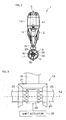
- FIG. 1A and FIG. 1B are side views of a marine vessel propulsion device 1 according to a first preferred embodiment of the present invention.
- FIG. 2 is a rear view of the marine vessel propulsion device 1 according to the first preferred embodiment of the present invention.
- FIG. 3 is a schematic view of a forward/rearward switching mechanism 19 according to the first preferred embodiment of the present invention.
- the marine vessel propulsion device 1 includes a bracket 2 that is attachable to the stern of a marine vessel V1, an outboard motor 3 that is attached to the stern through the bracket 2, and a propulsion unit 4 attached to the outboard motor 3.
- the marine vessel propulsion device 1 additionally includes a propeller 5 held by the propulsion unit 4.
- the marine vessel propulsion device 1 is preferably a hybrid type marine vessel propulsion device. In more detail, as shown in FIG. 1A and FIG.
- the marine vessel propulsion device 1 additionally includes an engine 6 and an electric motor 7 that are used to rotate the propeller 5 around a propeller axis A2 extending in a front-rear direction, an engine ECU (Electronic Control Unit) 8 programmed to control the engine 6, and a motor ECU 9 programmed to control the electric motor 7.
- an engine ECU Electronic Control Unit 8 programmed to control the engine 6
- a motor ECU 9 programmed to control the electric motor 7.
- the engine ECU 8 is arranged in the outboard motor 3, and the motor ECU 9 is arranged on the vessel.
- the motor ECU 9 may be arranged in the outboard motor 3 or in the propulsion unit 4. If the motor ECU 9 is arranged in the outboard motor 3, the motor ECU 9 may be cooled by cooling water that cools the engine 6. In this case, preferably, a cooling water passage is arranged so that the cooling water cools the motor ECU 9 before cooling the engine 6. According to this arrangement, the motor ECU 9 is cooled by low-temperature cooling water that has not yet been warmed by the engine 6. Therefore, the temperature of the motor ECU 9 can be sufficiently lowered.
- the outboard motor 3 is rotatable right and left around the steering axis A1 with respect to the hull H1.
- the propulsion unit 4 is preferably disposed behind the lower case 15.
- the propulsion unit 4 is preferably connected to the lower case 15 through a stay 17.
- the propulsion unit 4 rotates around the steering axis A1 together with the outboard motor 3. Therefore, when the outboard motor 3 rotates rightward and leftward around the steering axis A1, the propeller 5 also rotates rightward and leftward around the steering axis A1.
- the outboard motor 3 additionally includes a drive shaft 18 connected to the engine 6, a forward/rearward switching mechanism 19 connected to the drive shaft 18, and an engine output transmission shaft 20 connected to the forward/rearward switching mechanism 19.
- the drive shaft 18 extends in a vertical or substantially vertical direction.
- the drive shaft 18 is rotationally driven by the engine 6 around a central axis of the drive shaft 18.
- the drive shaft 18 is connected to the engine output transmission shaft 20 by the forward/rearward switching mechanism 19.
- the engine output transmission shaft 20 extends in the front-rear direction.
- the propeller 5 is connected to the rear end of the engine output transmission shaft 20. The propeller 5 rotates together with the engine output transmission shaft 20.
- the rotation of the engine 6 is transmitted to the propeller 5 through the drive shaft 18, the forward/rearward switching mechanism 19, and the engine output transmission shaft 20.
- the forward/rearward switching mechanism 19 performs switching among a forward state in which the engine output transmission shaft 20 rotates in the normal rotation direction, a rearward state in which the engine output transmission shaft 20 rotates in the reverse rotation direction, and a neutral state in which a connection between the drive shaft 18 and the engine output transmission shaft 20 is released. Therefore, the rotation state of the propeller 5 changes in accordance with the state of the forward/rearward switching mechanism 19.
- the forward/rearward switching mechanism 19 includes a pinion 21 connected to the drive shaft 18, a front gear 22 and a rear gear 23 both of which are engaged with the pinion 21, and a dog clutch 24 that is selectively engaged with either the front gear 22 or the rear gear 23.
- the forward/rearward switching mechanism 19 is preferably an electric type forward/rearward switching mechanism.
- the forward/rearward switching mechanism 19 additionally includes a shift actuator 25 that moves the dog clutch 24.
- the shift actuator 25 and the dog clutch 24 are connected together through a shift rod (not shown).
- the engine ECU 8 controls the forward/rearward switching mechanism 19 to selectively perform switching to any one of the forward state, the rearward state, and the neutral state by causing the shift actuator 25 to move the dog clutch 24 that serves as an output shaft of the forward/rearward switching mechanism 19.
- the pinion 21, the front gear 22, and the rear gear 23 are preferably all bevel gears.
- the front gear 22 and the rear gear 23 are disposed within a space therebetween in the front-rear direction.
- the dog clutch 24 is disposed between the front gear 22 and the rear gear 23.
- the engine output transmission shaft 20 penetrates through the front gear 22, the rear gear 23, and the dog clutch 24 in the front-rear direction.
- the front gear 22 and the rear gear 23 are rotatable around the central axis of the engine output transmission shaft 20 with respect to the engine output transmission shaft 20.
- the front gear 22 and the rear gear 23 are rotatably held by the lower case 15.
- the dog clutch 24 is connected to the engine output transmission shaft 20 by a spline. Therefore, the engine output transmission shaft 20 and the dog clutch 24 are relatively movable in the axial direction, and are rotatable around the central axis of the engine output transmission shaft 20.
- the dog clutch 24 and the engine output transmission shaft 20 are disposed coaxially.
- the dog clutch 24 is movable with respect to the engine output transmission shaft 20 between a forward position at which the dog clutch 24 is engaged with the front gear 22 and a rearward position at which the dog clutch 24 is engaged with the rear gear 23.
- the position (i.e., the position shown in FIG. 3 ) between the forward position and the rearward position is a neutral position at which the dog clutch 24 is spaced apart from both the front gear 22 and the rear gear 23.
- the engine ECU 8 causes the dog clutch 24 to move to any shift position of the forward position, the rearward position, and the neutral position by controlling the shift actuator 25.
- the forward position, the rearward position, and the neutral position correspond to the forward state, the rearward state, and the neutral state, respectively.
- the forward/rearward switching mechanism 19 performs switching to the forward state when the shift actuator 25 moves the dog clutch 24 to the forward position.
- the drive shaft 18 is driven by the engine 6 in a constant rotation direction.
- the pinion 21 rotates together with the drive shaft 18 around the central axis of the drive shaft 18.
- the front gear 22 and the rear gear 23 rotate in mutually opposite directions in response to the rotation of the pinion 21.
- the rotation of the front gear 22 is transmitted to the engine output transmission shaft 20 through the dog clutch 24 in a state in which the dog clutch 24 is disposed at the forward position and in which the front gear 22 is rotating.
- the engine output transmission shaft 20 rotates in the normal rotation direction.
- the rotation of the rear gear 23 is transmitted to the engine output transmission shaft 20 through the dog clutch 24 in a state in which the dog clutch 24 is disposed at the rearward position and in which the rear gear 23 is rotating.
- the engine output transmission shaft 20 rotates in the reverse rotation direction.
- the rotation of the drive shaft 18 is not transmitted to the engine output transmission shaft 20, and the drive shaft 18 runs idle in a state in which the dog clutch 24 is disposed at the neutral position.
- the marine vessel propulsion device 1 additionally includes a steering device 27 that steers the marine vessel V1.
- the steering device 27 may include a tiller handle 27a that is arranged to be operated by a vessel operator.
- the steering device 27 may additionally include a steering member 27b that is operable by the vessel operator and a steering unit 27c that rotates the outboard motor 3 right-handedly and left-handedly around the steering axis A1 in accordance with the operation of the steering member 27b.
- the tiller handle 27a is connected to the steering shaft 16.
- the steering shaft 16 rotates around the steering axis A1 together with the tiller handle 27a.
- FIG. 1A the steering device 27 may include a tiller handle 27a that is arranged to be operated by a vessel operator.
- the steering device 27 may additionally include a steering member 27b that is operable by the vessel operator and a steering unit 27c that rotates the outboard motor 3 right-handedly and left-handedly around the steering axis A1 in accordance with the operation of the steering
- the steering unit 27c is connected to a steering arm 27d that rotates around the steering axis A1 together with the steering shaft 16.
- the steering unit 27c rotates the steering arm 27d right-handedly and left-handedly around the steering axis A1.
- the steering member 27b may be mechanically connected to the steering unit 27c by a push-pull cable, or may be electrically connected to the steering unit 27c.
- the marine vessel propulsion device 1 additionally includes an output adjusting device 28 that performs the output adjustment of the marine vessel propulsion device I and that performs switching between directions of a thrust force.
- the output adjusting device 28 may include a throttle grip 28a and a shift lever 28b both of which are disposed on the tiller handle 27a.
- the throttle grip 28a is rotatably arranged around the central axis of the tiller handle 27a, and the shift lever 28b is arranged tiltably back and forth centering on its lower end.
- the throttle grip 28a and the shift lever 28b are operable by the vessel operator.
- the engine ECU 8 and the motor ECU 9 adjust the output of the marine vessel propulsion device 1 in accordance with the position of the throttle grip 28a.
- the engine ECU 8 and the motor ECU 9 switch the state of the forward/rearward switching mechanism 19 in accordance with the position of the shift lever 28b. For example, when the shift lever 28b is tilted back and forth, the engine ECU 8 and the motor ECU 9 cause the forward/rearward switching mechanism 19 to perform switching to a forward state or to a rearward state.
- the output adjusting device 28 may include a remote control unit 28c that functions as the throttle grip 28a and as the shift lever 28b.
- the remote control unit 28c may be electrically connected to either the engine ECU 8 or the motor ECU 9, or may be electrically connected to both the engine ECU 8 and the motor ECU 9.
- a command issued by the remote control unit 28c is sent to the steering unit 27c preferably via a wired communication or wireless communication.
- the remote control unit 28c may include a control lever 28d tiltable back and forth, or may include a joystick 28e tiltable back, forth, left and right. Additionally, the remote control unit 28c may include a wireless remote control 28f including four buttons, for example, or may include a touch panel 28g that communicates with at least one of the engine ECU 8 and the motor ECU 9 through a data communication network such as the Internet, for example.
- the output adjusting device 28 may include devices other than the above-described devices. In other words, the arrangement of the output adjusting device 28 is not limited to the above-described one.
- the output adjusting device 28 includes the remote control unit 28c and in which the remote control unit 28c includes the control lever 28d.
- the control lever 28d is movable back and forth between a forward output maximum position Fmax at which the lever is tilted most forwardly and a rearward output maximum position Rmax at which the lever is tilted most rearwardly.
- the output in the forward direction is the maximum at the forward output maximum position Fmax
- the output in the rearward direction i.e., backward direction
- the maximum at the rearward output maximum position Rmax is the maximum at the rearward output maximum position Rmax.
- a forward output minimum position Fmin and a rearward output minimum position Rmin are disposed between the forward output maximum position Fmax and the rearward output maximum position Rmax.
- the forward output minimum position Fmin is a position (zero position) at which the output in the forward direction is the minimum
- the rearward output minimum position Rmin is a position (zero position) at which the output in the rearward direction is the minimum.
- the forward output minimum position Fmin is a position closer to the forward output maximum position Fmax than to the rearward output minimum position Rmin.
- a range between the forward output maximum position Fmax and the forward output minimum position Fmin is a forward position (forward range) at which the forward/rearward switching mechanism 19 is maintained in a forward state, whereas a range between the rearward output maximum position Rmax and the rearward output minimum position Rmin is a rearward position (reverse range) at which the forward/rearward switching mechanism 19 is maintained in a rearward state.
- a range between the forward output minimum position Fmin and the rearward output minimum position Rmin is a neutral position at which the forward/rearward switching mechanism 19 is maintained in a neutral state.
- the present position of the control lever 28d is output from the remote control unit 28c to the engine ECU 8 and to the motor ECU 9.
- the engine ECU 8 causes the forward/rearward switching mechanism 19 to perform switching from the neutral state to the forward state.
- the engine ECU 8 and the motor ECU 9 cause the marine vessel propulsion device 1 to generate an output having an amount that is corresponding to the operational amount of the control lever 28d from the forward output minimum position Fmin, so that the marine vessel V1 is advanced.
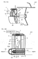
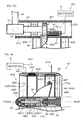
- FIG. 4 is a partial sectional view of a lower portion of the marine vessel propulsion device 1.
- FIG. 5 is a sectional view of a lower portion of the marine vessel propulsion device I.
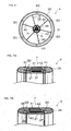
- FIG. 6 is a rear view of the propulsion unit 4.
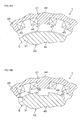
- FIG. 7A and FIG. 7B are sectional views showing an outer peripheral portion of the propulsion unit 4.
- the duct 26 is connected to the lower case 15 such that the duct 26 extends in the front-rear direction.
- the propeller 5 and the duct 26 are disposed coaxially.
- the propeller 5 includes a cylindrical rotational shaft 29 that extends along the propeller axis A2, a plurality of blades 30 disposed around the rotational shaft 29, and a cylindrical rim 31 that surrounds the blades 30.
- the rotational shaft 29 includes a cylindrical inner shaft portion 32 that extends along the propeller axis A2, an outer shaft portion 33 that surrounds the inner shaft portion 32 around the propeller axis A2, and a plurality of connection portions 34 by which the inner shaft portion 32 and the outer shaft portion 33 are connected together.
- the rear end of the engine output transmission shaft 20 protrudes rearwardly from the lower case 15.
- the rear end of the engine output transmission shaft 20 penetrates through the inner shaft portion 32.
- the inner shaft portion 32 is connected to the rear end of the engine output transmission shaft 20 by a bolt 35, for example. Therefore, the rotational shaft 29 rotates around the propeller axis A2 together with the engine output transmission shaft 20.
- connection portions 34 are disposed between the inner shaft portion 32 and the outer shaft portion 33.
- the connection portions 34 are spaced apart in the circumferential direction of the propeller 5.
- An exhaust passage 36 defined between the inner shaft portion 32 and the outer shaft portion 33 communicates with the lower case 15. Exhaust gas generated by the engine 6 flows into the exhaust passage 36 from the front. Thereafter, the exhaust gas that has flowed into the exhaust passage 36 is discharged rearwardly from the exhaust passage 36. As a result, the exhaust gas generated by the engine 6 is discharged into the water.
- the blades 30 are spaced apart in the circumferential direction of the propeller 5.
- Each blade 30 preferably has a generally triangular shape that extends from an inner peripheral surface of the rim 31 toward the propeller axis A2.
- the blades 30 may be a flat plate, or may be a curved plate including a curved portion.
- the outer ends (i.e., ends on the side of the rim 31) of the blades 30 are fixed to the rim 31, whereas inner ends (i.e., ends on the side opposite to the rim 31) of the blades 30 are fixed to the rotational shaft 29. Therefore, the rotational shaft 29, the blades 30, and the rim 31 are rotatable together around the propeller axis A2. Therefore, when the engine output transmission shaft 20 rotates around the propeller axis A2, the rotational shaft 29, the blades 30, and the rim 31 rotate around the propeller axis A2 together with the engine output transmission shaft 20.
- the rim 31 surrounds the propeller axis A2 inside the duct 26.
- the rim 31 is contained in an annular groove 37 provided in the inner peripheral portion of the duct 26.
- the annular groove 37 is more hollow than the inner peripheral surface of the duct 26, and is continuous over its whole circumference.
- the central axis of the rim 31 and that of the duct 26 are disposed on the propeller axis A2.
- the rim 31 is rotatable around the propeller axis A2 with respect to the duct 26 in a state of being contained in the annular groove 37. Therefore, the propeller 5 is rotatable around the propeller axis A2 with respect to the duct 26.
- the rim 31 may not be held by the duct 26, or may be held by the duct 26 with a plurality of bearings therebetween.
- the rim 31 may be supported by the duct 26 with two thrust bearings B1 and a radial bearing B2 therebetween.
- the rim 31 may be supported by the duct 26 with a plurality of tapered roller bearings B3 therebetween.
- the thrust bearing B1 and the radial bearing B2 may be ball bearings, or may be roller bearings, or may be different types of bearings.
- one of the thrust bearings B1 is disposed between a front end surface of the rim 31 and the duct 26, and the other thrust bearing B1 is disposed between a rear end surface of the rim 31 and the duct 26.
- the radial bearing B2 is disposed between an outer peripheral surface of the rim 31 and the duct 26.
- the two thrust bearings B1 support the rim 31 rotatably around the propeller axis A2, and restrict an amount of movement of the rim 31 in the axial direction (i.e., A direction along the propeller axis A2).
- the radial bearing B2 supports the rim 31 rotatably around the propeller axis A2, and restricts an amount of movement of the rim 31 in the radial direction. Therefore, the movement amount of the propeller 5 in the axial direction and that of the propeller 5 in the radial direction are restricted by the thrust bearings B1 and the radial bearing B2.
- the tapered roller bearings B3 are preferably arranged as a plurality of pairs. As is understood from a combination of FIG. 6 and FIG. 7B , the tapered roller bearings B3 serving as a pair are spaced apart back and forth so as to coincide with each other when seen from the front-rear direction.
- the front tapered roller bearing B3 is disposed between the front end surface of rim 31 and the duct 26, whereas the rear tapered roller bearing B3 is disposed between the rear end surface of the rim 31 and the duct 26.
- the pairs of tapered roller bearings B3 are spaced apart in the circumferential direction.
- the tapered roller bearing B3 includes a support shaft 38 held by the duct 26, an inner ring 39 that surrounds the support shaft 38, and a plurality of rollers 40 disposed around the inner ring 39.
- the rollers 40 are held by an annular retainer (not shown).
- Each roller 40 is rotatable around the inner ring 39 while rotating around its central axis (while turning on its own central axis).
- Each roller 40 is in contact with the front end surface or the rear end surface of the rim 31.
- the tapered roller bearings B3 support the rim 31 so as to be rotatable around the propeller axis A2, and restrict the amount of movement of the rim 31 in the axial direction and that of movement of the rim 31 in the radial direction. Therefore, the amount of movement of the propeller 5 in the axial direction and that of movement of the propeller 5 in the radial direction are restricted by the tapered roller bearings B3.
- the propulsion unit 4 includes a propeller speed detector 43 that detects the rotation speed of the propeller 5.
- the propeller speed detector 43 is disposed in the duct 26.
- the rotation angle of the electric motor 7 i.e., the rotation angle of a rotor 42
- the electric motor 7 includes an annular stator 41 defined by a portion of the duct 26 and the cylindrical rotor 42 defined by a portion of the rim 31.
- the duct 26 includes the stator 41 disposed between the outer peripheral surface of the duct 26 and a bottom surface of the annular groove 37
- the rim 31 includes the rotor 42 disposed on an outer peripheral portion of the rim 31.
- the stator 41 and the rotor 42 surround the propeller axis A2.
- the stator 41 and the rotor 42 face each other in the radial direction of the propeller 5 with a space between the stator 41 and the rotor 42.
- the stator 41 includes an annular stator core 44 preferably made of a soft magnetic material, such as a magnetic steel sheet, and a plurality of coils 45 that are wound onto the stator core 44.
- the rotor 42 may be a permanent-magnet rotor that includes a cylindrical rotor core 46 preferably made of a soft magnetic material and a plurality of magnets 47 held by the rotor core 46.
- the electric motor 7 may be a permanent-magnet type direct-current motor.
- the rotor 42 may be a cylindrical salient poled rotor that includes a plurality of salient poles 48 spaced apart in the circumferential direction of the propeller 5 and that is preferably made of a soft magnetic material.
- the electric motor 7 may be a switched reluctance motor.
- the electric motor 7 may be a direct-current motor provided with a brush, or may be a brushless motor, or may be another type of motor.
- the coils 45 are arranged in the circumferential direction of the propeller 5.
- the coils 45 define an annular row that surrounds the propeller axis A2.
- the magnets 47 are arranged in the circumferential direction of the propeller 5, and define an annular row that surrounds the propeller axis A2.
- the coils 45 may surround the propeller axis A2, and may define a plurality of annular rows arranged in the axial direction of the propeller 5.
- the magnets 47 may surround the propeller axis A2, and may define a plurality of annular rows arranged in the axial direction of the propeller 5.
- two annular rows arranged in the axial direction of the propeller 5 may be defined by the coils 45, the number of windings of which is reduced to half thereof. According to this arrangement, it is possible to reduce the thickness of the electric motor 7 in the radial direction while minimizing a change in the maximum output of the electric motor 7.
- the motor ECU 9 controls the power supply to the stator 41. In other words, based on an output of the propeller speed detector 43, the motor ECU 9 controls the power supply to the stator 41, and hence controls the rotation direction and the rotation speed of the rotor 42.
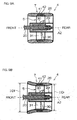
- FIG. 9A and FIG. 9B are sectional views showing the propulsion unit 4.
- FIG. 10A and FIG. 10B are sectional views showing the blade 30 taken along line X-X in FIG. 6 .
- the inner diameter of the front end of the duct 26 may be equal to the inner diameter of the rear end of the duct 26.
- the cross section of the blade 30 may be linear. According to this arrangement, if the rotation speed of the propeller 5 is the same, the propulsion unit 4 can generate a thrust force in the backward direction that is substantially the same in strength as a thrust force in the forward direction.
- FIG. 11 is a block diagram showing an electric arrangement of the marine vessel propulsion device 1.
- the marine vessel propulsion device 1 includes a control device X1 including the engine ECU 8 and the motor ECU 9.
- the engine 6 and the electric motor 7 are connected to the control device X1.
- the shift actuator 25 and the remote control unit 28c are connected to the control device X1.
- the engine 6, the electric motor 7, and the shift actuator 25 are controlled by the control device X1 based on a command that is input from the remote control unit 28c to the control device X1.
- the engine 6 includes an electric generator (e.g., a flywheel magneto) 49 that generates electricity in response to the rotation of the crankshaft.
- the electric generator 49 is connected to the control device X1.
- the control device X1 is connected to the battery 12. Electric power generated by the electric generator 49 is supplied to the battery 12 through the control device X1.
- the engine 6 additionally includes an engine speed detector 50 that detects the rotation speed of the engine 6 (i.e., that detects the rotation speed of the crankshaft).
- the engine speed detector 50 is connected to the control device X1.
- the propeller speed detector 43 that detects the rotation speed of the propeller 5 is connected to the control device X1.
- the marine vessel propulsion device I additionally includes a fuel remaining amount detector 51 that detects a remaining amount of fuel in the fuel tank 11, a power remaining amount detector 52 that detects a remaining amount of electric power in the battery 12, and an alarm device 53 that issues an alarm to persons on the marine vessel.
- the fuel remaining amount detector 51 may be a float sensor that detects a remaining amount of fuel based on the position of a float disposed in the fusel tank 11, or may be a fuel remaining amount estimating portion that estimates a remaining amount of fuel from an injection amount of fuel jetted to produce an air-fuel mixture of air and fuel.
- the power remaining amount detector 52 may be a power remaining amount estimating portion that estimates a remaining amount of electric power from the voltage of the battery 12 or from the integrated value of input electric current or output electric current of the battery 12.
- the power remaining amount estimating portion may be disposed in the control device X1, or may be disposed in a device other than the control device X1.
- the fuel remaining amount estimating portion may be disposed in the control device X1, or may be disposed in a device other than the control device X1.
- the marine vessel propulsion device I additionally includes an operation mode selection switch 54 that is operated by a vessel operator.
- the operation mode selection switch 54 is connected to the control device X1.
- the operation mode of the marine vessel propulsion device 1 is selected through the operation of the operation mode selection switch 54 by the vessel operator.
- the control device X1 operates the marine vessel propulsion device 1 in the operation mode selected by the vessel operator.
- the operation mode of the marine vessel propulsion device 1 includes an engine mode that causes only the engine 6 to drive the propeller 5, an electric mode that causes only the electric motor 7 to drive the propeller 5, and an assist mode that causes both the engine 6 and the electric motor 7 to drive the propeller 5.
- the operation mode of the marine vessel propulsion device 1 additionally includes an automatic selection mode in which the control device X1 selects any one of the engine mode, the electric mode, and the assist mode in accordance with the position of the control lever 28d (see FIG. 1A ).
- FIG. 12 is a graph showing a relationship between the operational amount of the control lever 28d and the output of the marine vessel propulsion device 1.
- the control device X1 when the operational amount of the control lever 28d is below a first operational amount as shown in FIG. 12 , the control device X1 causes only the electric motor 7 to drive the propeller 5 so as to generate an output having an amount that is proportional to the operational amount of the control lever 28d. In this case, the control device X1 may stop the operation of the engine 6, or may cause the forward/rearward switching mechanism 19 to perform switching to the neutral state so as to prevent the output of the engine 6 from being transmitted to the propeller 5.
- the control device X1 When the operational amount of the control lever 28d is greater than the first operational amount and is not greater than the second operational amount, the control device X1 causes the engine 6 and the electric motor 7 to drive the propeller 5 so as to generate an output having an amount that is proportional to the operational amount of the control lever 28d. As shown in FIG. 12 , in this range, the control device X1 may increase the output of the engine 6 in proportion to an increase in the operational amount of the control lever 28d, while decreasing the output of the electric motor 7, so as to generate an output having an amount that is proportional to the operational amount of the control lever 28d.
- the control device X1 When the operational amount of the control lever 28d is greater than the second operational amount, the control device X1 is programmed to cause only the engine 6 to drive the propeller 5 so as to generate an output having an amount that is proportional to the operational amount of the control lever 28d. As described below, if the vessel operator does not intend to suddenly accelerate the marine vessel V1 and if the remaining amount of the battery 12 has not reached an upper limit, the control device X1 causes the electric motor 7 to generate electric power, and supplies the electric power generated by the electric motor 7 to the battery 12. Therefore, a torque (negative torque) that is opposite in direction to a torque transmitted from the engine 6 to the propeller 5 is applied to the propeller 5 from the electric motor 7, and the output is decreased.
- the control device X1 is programmed to select a power source to drive the propeller 5 in accordance with the operational amount of the control lever 28d from the output minimum position as described above.
- the first and second operational amounts based on which power source is selected may be specific constants regardless of the situation of the marine vessel propulsion device 1. Additionally, as described below, the first and second operational amounts may be variables that change in accordance with the situation of the marine vessel propulsion device 1, such as the operation situation of the control lever 28d or the remaining amount of the battery 12.
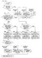
- the control device X1 is programmed to determine whether both the engine 6 and the electric motor 7 can be continuously operated (S1). In detail, the control device X I determines whether, for example, the remaining amount of the fuel is not less than a predetermined value and whether the temperature of the engine 6 is not higher than a predetermined value. Furthermore, the control device X1 deternines whether, for example, the remaining amount of the battery 12 is not less than a predetermined value. In other words, the control device X1 confirms that the remaining amount of the fuel is not small and that the engine 6 is not high in temperature. Furthermore, the control device X1 confirms that the remaining amount of electric power stored in the battery 12 is not small.
- the control device X1 causes the electric motor 7 to drive the propeller 5, and hence generates an output having an amount corresponding to the position of the control lever 28d (S2). Likewise, if only the electric motor 7 cannot be continuously operated (if No at S1), the control device X1 causes the engine 6 to drive the propeller 5, and hence generates an output having an amount corresponding to the position of the control lever 28d (S3). If both the engine 6 and the electric motor 7 cannot be continuously operated (if No at S1), the control device X1 causes the alarm device 53 (see FIG. 11 ) to issue an alarm (S4).
- the control device X1 is programmed to calculate the rate of change of the position of the control lever 28d from a predetermined time (e.g., from immediately before the performance of a calculation) until the present time based on a detection value of the remote control unit 28c. For example, if the control lever 28d is disposed at the forward position, the control device X1 calculates what percentage of a range from the forward output minimum position Fmin (see FIG. 1A ) to the forward output maximum position Fmax (see FIG. 1A ) that the control lever 28d has moved.
- control device X1 determines whether the lever-position change rate is equal to or greater than a predetermined value (S5). In other words, the control device X1 determines whether the vessel operator has quickly moved the control lever 28d by a large movement amount in order to rapidly accelerate the marine vessel V1.
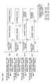
- the control device X1 is programmed to set a1 as a first operational amount (see FIG. 12 ), and to set b1 as a second operational amount (see FIG. 12 ) (S8). If the remaining amount of the battery 12 is less than the predetermined value at S6 (if No at S6), the control device X1 is programmed to set a2 as a first operational amount, and to set b2 as a second operational amount (S9). As shown in FIG. 13B , a2 is smaller than a1 and is a value of zero or more, whereas b2 is smaller than b1 and is a value of zero or more. Therefore, if the lever-position change rate is small and if the remaining amount of the battery 12 is not sufficient, the control device X1 makes a range (electric mode and assist mode) in which the electric motor 7 rotates the propeller 5 narrower than usual.
- the control device X1 makes the upper limit of the assist mode greater than usual. As shown in FIG. 13B , a4 is smaller than a3 and is a value of zero or more, whereas b4 is smaller than b3 and is a value of zero or more. Therefore, if the remaining amount of the battery 12 is not sufficient even if the lever-position change rate is large, the control device X1 makes the range in which the electric motor 7 rotates the propeller 5 narrower than a case in which the remaining amount of the battery 12 is sufficient.
- each of the values "a” and "b” is set to a smaller value when the remaining amount of the battery 12 is small than when the remaining amount of the battery 12 is large if the lever-position change rate is the same as shown in a first row (S8) and a second row (S9) of FIG. 13B .
- each of the values "a” and “b” is set to a smaller value when the remaining amount of the battery 12 is small than when the remaining amount of the battery 12 is large if the lever-position change rate is the same as shown in a third row (S10) and a fourth row (S11) of FIG. 13B .
- the control device X1 sets the first operational amount and the second operational amount in accordance with the lever-position change rate and the remaining amount of the battery 12. Thereafter, as shown in FIG. 13A , based on the first operational amount and the second operational amount that have been set thereby and based on the present position of the control lever 28d, the control device X1 is programmed to select any one of the modes in which the marine vessel propulsion device 1 is operated (S12). If the electric mode is selected, the control device X1 operates the marine vessel propulsion device 1 in the electric mode as described below (S13). If the assist mode is selected, the control device X1 operates the marine vessel propulsion device 1 in the assist mode (S14).
- control device X1 generates an output having an amount corresponding to the position of the control lever 28d while rotating the propeller 5 by the engine 6 and the electric motor 7. If the engine mode is selected, the control device X I operates the marine vessel propulsion device 1 in the engine mode as described below (S15).
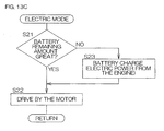
- FIG. 13C is a flowchart for describing the electric mode.
- control device X1 is programmed to control the electric motor 7 so as to generate an output having an amount corresponding to the position of the control lever 28d (S22).
- the control device X1 causes the dog clutch 24 (see FIG. 3 ) to be moved to the neutral position, and rotates the engine 6 at a rotation speed not less than an idle rotation speed. Thereafter, the control device X1 supplies electric power generated by the electric generator 49 (see FIG. 11 ) of the engine 6 to the battery 12, and charges the battery 12
- control device X1 controls the electric motor 7 to drive the propeller 5 so as to generate an output having an amount corresponding to the position of the control lever 28d while charging the battery 12 (S22).
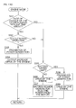
- the control device X1 determines whether the lever-position change rate is equal to or greater than the predetermined value (S31). If the lever-position change rate is equal to or greater than the predetermined value (if Yes at S31), the control device X1 determines whether the control lever 28d has been operated in a direction in which the marine vessel V I is accelerated (S32). If the control lever 28d has been operated in the direction in which the marine vessel V1 is accelerated (if Yes at S32), the control device X1 prohibits the electric motor 7 from generating electric power, for example, by temporarily cutting off an electric circuit (S33). In other words, the control device X1 prevents the electric motor 7 from working as a load on the engine 6. Thereafter, the control device X1 generates an output having an amount corresponding to the position of the control lever 28d by increasing the output of the engine 6 (S34).
- the control device X1 supplies electric power generated by the electric motor 7 to the battery 12 (S37).
- the control device X1 prohibits the electric motor 7 from generating electric power in order to prevent overcharging the battery 12 (S38).
- the control device X1 generates an output having an amount corresponding to the position of the control lever 28d by controlling the engine 6 in a state in which power generation is prohibited (S39).
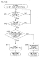
- FIG. 14A is a flowchart describing when a shift-in operation in which the vessel operator moves the control lever 28d from the neutral position to the forward position or to the rearward position is performed.
- the control device X1 causes the dog clutch 24 to be moved from the neutral position to the forward position by controlling the shift actuator 25 (S44). As a result, the dog clutch 24 is engaged with the front gear 22, and the rotation of the engine 6 is transmitted to the propeller 5. On the other hand, if the speed difference is equal to or greater than the first threshold (if Yes at S43), the control device X1 reduces the speed difference by controlling at least one of the engine 6 and the electric motor 7 (S45).
- control device X1 When the control device X1 reduces the speed difference, the control device X1 may increase or decrease the rotation speed of the front and rear gears 22 and 23 by controlling the engine 6. Alternatively, the control device X1 may increase or decrease the rotation speed of the dog clutch 24 by controlling the electric motor 7. Of course, the control device X1 may reduce the speed difference by controlling both the engine 6 and the electric motor 7. If the rotation speed of the engine 6 is in a state of being decreased, the control device X1 may maintain the rotation speed of the electric motor 7 at a fixed speed until the rotation speed of the engine 6 falls to or below the predetermined value.
- the control device X1 reduces the speed difference, and thereafter again determines whether the speed difference is equal to or greater than the first threshold (S43). If the speed difference is less than the first threshold (if No at S43), the control device X1 causes the dog clutch 24 to be moved to the forward position (S44). If the speed difference is equal to or greater than the first threshold (if Yes at S43), the control device X1 again reduces the speed difference (S45). The control device X1 decreases the speed difference to a value smaller than the first threshold.
- the control device X1 determines whether the lever position is the rearward position (S46). If the lever position is the rearward position (if Yes at S46), the control device X 1 determines whether the speed difference is equal to or greater than a second threshold (S47).
- the second threshold may be a value equal to the first threshold, or may be a value greater or smaller than the first threshold. In other words, the threshold used when the shift position is switched from the neutral position to the forward position and the threshold used when the shift position is switched from the neutral position to the rearward position may be equal to each other or may be different from each other.
- FIG. 14B is a flowchart describing when a shift-out operation in which the vessel operator moves the control lever 28d from the forward or rearward position to the neutral position is performed.
- the control device X1 determines whether the shift position (the position of the dog clutch 24 (see FIG. 3 )) is the forward position or the rearward position (S51). If the shift position is the forward position or the rearward position (if Yes at S51), the control device X1 determines whether the lever position (the position of the control lever 28d (see FIG. 1A )) is the neutral position (S52). If the lever position is the neutral position (if Yes at S52), i.e., if the vessel operator has moved the control lever 28d from the forward or rearward position to the neutral position, the control device X1 determines whether the rotation speed of the propeller 5 is equal to or below a cut-off speed (shift-out cut-off speed) (S53).
- the cut-off speed may be a fixed speed (a constant), or may be an arbitrary speed (a variable) that is set based on, for example, the lever-position change rate described above.
- the control device X1 causes the dog clutch 24 to be moved from the forward or rearward position to the neutral position (S54). As a result, the dog clutch 24 is disengaged from the front gear 22 or the rear gear 23, and a mechanical connection between the drive shaft 18 and the engine output transmission shaft 20 is released.
- the control device X1 decreases the rotation speed of the propeller 5 by controlling the electric motor 7 (S55).
- control device X1 may maintain the output of the electric motor 7 at a fixed output level until the rotation speed of the propeller 5 falls to or below the cut-off speed.
- control device X1 may decrease the rotation speed of the propeller 5 by decreasing the output of the electric motor 7.
- the control device X1 decreases the rotation speed of the propeller 5, and thereafter again determines whether the rotation speed of the propeller 5 is equal to or below the cut-off speed (S53). If the rotation speed of the propeller 5 is equal to or below the cut-off speed (if Yes at S53), the control device X1 causes the dog clutch 24 to be moved from the forward or rearward position to the neutral position (S54). If the rotation speed of the propeller 5 is greater than the cut-off speed (if No at S53), the control device X1 again decreases the rotation speed of the propeller 5 (S55). The control device X1 decreases the rotation speed of the propeller 5 to or below the cut-off speed in this manner, and then causes the dog clutch 24 to be moved from the forward or rearward position to the neutral position (S54).
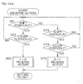
- FIG. 15A is a flowchart describing when a reverse operation in which the vessel operator moves the control lever 28d from either one of the forward position and the rearward position to the other one is performed.
- FIG. 15B is a flowchart for describing an F ⁇ R reverse action that reverses the rotation direction of the propeller 5 from the forward direction (normal rotation direction) to the backward direction (reverse rotation direction) and an R ⁇ F reverse action that reverses the rotation direction of the propeller 5 from the backward direction to the forward direction.
- the control device X1 determines whether the rotation speed of the propeller 5 is equal to or below an F ⁇ R cut-off speed (S64).
- the F ⁇ R cut-off speed may be a fixed speed (a constant), or may be an arbitrary speed (a variable) that is set based on, for example, the lever-position change rate described above.
- the F ⁇ R cut-off speed may be a speed equal to the shift-out cut-off speed described above, or may be greater or smaller than the shift-out cut-off speed.
- the control device X1 causes the dog clutch 24 to be moved from the forward position to the neutral position (S65). As a result, the dog clutch 24 is disengaged from the front gear 22, and a mechanical connection between the drive shaft 18 and the engine output transmission shaft 20 is released.
- the control device X1 decreases the rotation speed of the propeller 5 by controlling the electric motor 7 in the same manner as at S55 (see FIG. 14B ) (S66).
- the control device X1 determines whether the operation mode of the marine vessel propulsion device 1 is the assist mode or the engine mode (which includes the assist mode and the engine mode of the automatic selection mode) (S67). If the operation mode is neither the assist mode nor the engine mode (if No at S67), the control device X1 reverses the propeller 5 by controlling the electric motor 7 (S68). In other words, the control device X1 switches the rotation direction of the propeller 5 from the normal rotation direction to the reverse rotation direction by causing the electric motor 7 to drive the propeller 5 in a state in which a mechanical connection between the engine 6 and the propeller 5 has been released. Thereafter, the control device X1 causes the electric motor 7 to accelerate the propeller 5 in the reverse rotation direction up to a propeller rotation speed corresponding to an output command.
- the control device X1 determines whether a speed difference that is a difference between the rotation speed (absolute value) of the engine 6 and the rotation speed (absolute value) of the propeller 5 is not less than a third threshold (S70).
- the control device X1 causes the dog clutch 24 to be moved from the neutral position to the rearward position (S71). As a result, the dog clutch 24 is engaged with the rear gear 23, and the rotation of the engine 6 is transmitted to the propeller 5. Therefore, the propeller 5 is driven in the reverse rotation direction by both the engine 6 and the electric motor 7.
- the control device X1 reduces the speed difference by controlling the engine 6 and the electric motor 7 in the same manner as at S45 (see FIG. 14A ) (S72). Thereafter, the control device X1 againn determines whether the speed difference is equal to or greater than the third threshold (S70).
- the control device X1 determines whether the shift position is the rearward position (S73). If the shift position is the rearward position (if Yes at S73), the control device X1 determines whether the lever position is the forward position (S74). If the lever position is the forward position (if Yes at S74), i.e., if the vessel operator has moved the control lever 28d from the rearward position to the forward position, the control device X1 performs an R ⁇ F reverse action (S75). In detail, as shown in FIG.
- the control device X1 determines whether the rotation speed of the propeller 5 is equal to or below the R ⁇ F cut-off speed (S64).
- the R ⁇ F cut-off speed may be a fixed speed (a constant), or may be an arbitrary speed (a variable) that is set based on, for example, the lever-position change rate described above.
- the R ⁇ F cut-off speed may be a speed equal to the shift-out cut-off speed described above, or may be greater or smaller than the shift-out cut-off speed.
- the R ⁇ F cut-off speed may be a speed equal to the F ⁇ R cut-off speed, or may be greater or smaller than the F ⁇ R cut-off speed.
- the control device X1 moves the dog clutch 24 from the rearward position to the neutral position (S65). As a result, the dog clutch 24 is disengaged from the rear gear 23, and a mechanical connection between the drive shaft 18 and the engine output transmission shaft 20 is released.
- the control device X1 decreases the rotation speed of the propeller 5 in the same manner as at S55 (see FIG. 14B ) (S66). As a result, the rotation speed of the engine 6 and that of the propeller 5 are decreased.
- the control device X1 decreases the rotation speed of the propeller 5, and thereafter again determines whether the rotation speed of the propeller 5 is equal to or below the R ⁇ 4F cut-off speed (S64). If the rotation speed of the propeller 5 is equal to or below the R ⁇ F cut-off speed (if Yes at S64), the control device X1 moves the dog clutch 24 from the rearward position to the neutral position (S65). If the rotation speed of the propeller 5 is greater than the R ⁇ F cut-off speed (if No at S64), the control device X1 again decreases the rotation speed of the propeller 5 (S66). The control device X1 causes the rotation speed of the propeller 5 to fall to or below the R ⁇ F cut-off speed in this manner, and then causes the dog clutch 24 to be moved from the rearward position to the neutral position (S65).
- the control device X1 determines whether the operation mode of the marine vessel propulsion device 1 is the assist mode or the engine mode (S67). If the operation mode is neither the assist mode nor the engine mode (if No at S67), the control device X1 reverses the propeller 5 by controlling the electric motor 7 (S68). In detail, the control device X1 switches the rotation direction of the propeller 5 from the reverse rotation direction to the normal rotation direction by causing the electric motor 7 to drive the propeller 5 in a state in which a mechanical connection between the engine 6 and the propeller 5 has been released. Thereafter, the control device X1 causes the electric motor 7 to accelerate the propeller 5 in the normal rotation direction up to a propeller rotation speed corresponding to an output command.
- the control device X1 determines whether the speed difference is equal to or greater than a fourth threshold (S70).
- the control device X1 If the speed difference is less than the fourth threshold (if No at S70), the control device X1 causes the dog clutch 24 to be moved from the neutral position to the forward position (S71). As a result, the dog clutch 24 is engaged with the front gear 22, and the rotation of the engine 6 is transmitted to the propeller 5. Therefore, the propeller 5 is driven in the normal rotation direction by both the engine 6 and the electric motor 7.
- the control device X1 reduces the speed difference by controlling the engine 6 and the electric motor 7 in the same manner as at S45 (see FIG. 14A ) (S72). Thereafter, the control device X1 again determines whether the speed difference is equal to or greater than the fourth threshold (S70).
- the propeller 5 including the blades 30 and the rim 31 is surrounded by the duct 26.
- the engine 6 rotates the blades 30 around the propeller axis A2 with respect to the duct 26.
- the electric motor 7 rotates the blades 30 around the propeller axis A2 with respect to the duct 26.
- the propeller 5 is rotationally driven around the propeller axis A2 by either the engine 6 or the electric motor 7 or by both the engine 6 and the electric motor 7. As a result, a thrust force that propels the marine vessel V1 is generated.
- the engine 6 and the electric motor 7 can rotate the propeller 5 independently of each other, and therefore the structure of the marine vessel propulsion device 1 can be simplified.
- the propulsion unit 4 is attached to the lower case 15, and therefore the same components as those of existing outboard motors can be used in an arrangement exclusive of the lower portion (lower unit) of the outboard motor 3.
- the electric motor 7 is disposed in the water when the marine vessel V1 is sailing, and therefore it is difficult for a motor sound generated from the electric motor 7 to travel to persons on the marine vessel. Therefore, the quietness of the marine vessel propulsion device 1 can be improved.
- a main difference between the second preferred embodiment and the above-described first preferred embodiment is that the propulsion unit is disposed in front of the lower case.
- FIG. 16A is a partial sectional view of a lower portion of a marine vessel propulsion device 201 according to the second preferred embodiment of the present invention.
- FIG. 16B is a sectional view of a propulsion unit 4 according to the second preferred embodiment of the present invention.
- the same reference numerals as in FIGS. 1 to 15 are given to the components corresponding to the components shown in FIGS. 1 to 15 , and a description of these components is omitted.
- the marine vessel propulsion device 201 preferably has the same arrangement as the marine vessel propulsion device I according to the first preferred embodiment exclusive of the lower portion (lower unit) of the outboard motor 3.
- the marine vessel propulsion device 201 includes a lower case 215 instead of the lower case 15 according to the first preferred embodiment.
- the lower case 215 includes an exhaust portion 255 disposed at the rear of the lower case 215.
- the exhaust portion 255 defines an exhaust port through which exhaust gas generated by the engine 6 (see FIG. 1A ) is discharged rearwardly.
- the propulsion unit 4 is disposed in front of the lower case 215. Therefore, the propeller 5 is disposed in front of the forward/rearward switching mechanism 19.
- the propulsion unit 4 is connected to the lower case 215 through the stay 17. As shown in FIG. 16B , the front end of the engine output transmission shaft 20 protrudes forwardly from the lower case 215. The front end of the engine output transmission shaft 20 penetrates through the inner shaft portion 32 in the front-rear direction. The inner shaft portion 32 is connected to the front end of the engine output transmission shaft 20 by the bolt 35, for example. The front end of the rotational shaft 29 is covered with a cover 256 that is a forwardly convex hemisphere.
- a main difference between the third preferred embodiment and the above-described first preferred embodiment is that the propulsion unit is disposed below the lower case.
- FIG. 17A is a partial sectional view of a lower portion of a marine vessel propulsion device 301 according to the third preferred embodiment of the present invention.
- FIG. 17B is a rear view of the propulsion unit 4 according to the third preferred embodiment of the present invention.
- FIG. 17C is a sectional view of the propulsion unit 4 according to the third preferred embodiment of the present invention.
- the same reference numerals as in FIGS. 1 to 16B are given to the components corresponding to the components shown in FIGS. 1 to 16B , and a description of these components is omitted.
- the marine vessel propulsion device 301 preferably has the same arrangement as the marine vessel propulsion device I according to the first preferred embodiment exclusive of the lower portion (lower unit) of the outboard motor 3.
- the marine vessel propulsion device 301 includes a lower case 315 instead of the lower case 15 according to the first preferred embodiment.
- the marine vessel propulsion device 301 additionally includes a propulsion unit 304 instead of the propulsion unit 4 according to the first preferred embodiment.
- the propulsion unit 304 preferably has the same arrangement as the propulsion unit 4 according to the first preferred embodiment exclusive of the propeller.
- the propulsion unit 304 includes a propeller 305 instead of the propeller 5 according to the first preferred embodiment.
- the lower case 315 includes an exhaust portion 255 disposed at the rear of the lower case 315.
- the propulsion unit 304 is disposed below the lower case 315.
- the upper end of the duct 26 is connected to the lower case 315.
- the propeller 305 is disposed below the dog clutch 24.
- the propeller 305 includes the blades 30 and the rim 31.
- the propeller 305 is not provided with the rotational shaft 29.
- the rim 31 is held by the duct 26 with the bearings B1 to B3 (see FIG. 7A and FIG. 7B ) arranged therebetween. As a result, the propeller 305 is held by the duct 26.
- the marine vessel propulsion device 301 additionally includes a gear transmission mechanism 357 that transmits the power of the engine 6 to the rim 31.
- the gear transmission mechanism 357 includes a driving gear 358 connected to the engine output transmission shaft 20 and a driven gear 359 disposed on the outer periphery of the rim 31.
- the driving gear 358 and the driven gear 359 may mesh with each other, or may mesh with a shared intermediate gear.
- FIG. 17C shows a state in which the driving gear 358 meshes with the driven gear 359.
- the driving gear 358 rotates together with the engine output transmission shaft 20, and the driven gear 359 rotates together with the rim 31.
- the rotation of the engine output transmission shaft 20 is transmitted to the rim 31 while being decelerated by the gear transmission mechanism 357. As a result, its rotation is transmitted to the rim 31 in a state in which the power of the engine 6 has been amplified, and the propeller 305 rotates around the propeller axis A2 with respect to the duct 26.
- a main difference between the fourth preferred embodiment and the above-described second preferred embodiment is that a propeller pitch (i.e., a distance advanced by one rotation of the propeller) can be changed.
- FIG. 18 is a sectional view of a propulsion unit 404 according to the fourth preferred embodiment of the present invention.
- FIG. 19A and FIG. 19B are views for describing the inclination angle of the blade 30 with respect to the propeller axis A2.
- the same reference numerals as in FIGS. 1 to 17C are given to the components corresponding to the components shown in FIGS. 1 to 17C , and a description of these components is omitted.
- the marine vessel propulsion device 401 preferably has the same arrangement as the marine vessel propulsion device 201 according to the second preferred embodiment exclusive of the propulsion unit.
- the marine vessel propulsion device 401 includes the propulsion unit 404 instead of the propulsion unit 4.
- the propulsion unit 404 includes a propeller 405 rotatable around the propeller axis A2, an electric motor 407 that rotates the propeller 405 around the propeller axis A2, and a duct 26 that surrounds the propeller 405 around the propeller axis A2.
- the propeller 405 is held by the duct 26.
- the propeller 405 and the duct 26 are disposed coaxially.
- the propeller 405 includes a cylindrical front rotational shaft 462 and a cylindrical rear rotational shaft 463 that extend along the propeller axis A2, a plurality of blades 30 disposed around the front and rear rotational shafts 462 and 463, and a cylindrical rim 430 that surrounds the blades 30.
- FIG. 18 to FIG. 19B only one blade 30 is shown, and the other blades 30 are omitted from the figures.
- Each blade 30 is supported by the rim 430.
- the rim 430 includes a cylindrical front rim 460 that surrounds the blades 30 and a rear rim 461 that surrounds the blades 30 behind the front rim 460.
- the front rotational shaft 462 is supported by a center shaft 464 that extends along the propeller axis A2 with two thrust bearings B401 and two radial bearings B402 arranged therebetween.
- the center shaft 464 is fixed to the cover 256.
- the cover 256 is fixed to the duct 26 by a fixing member (not shown). Therefore, the front rotational shaft 462 is rotatable around the propeller axis A2 with respect to the duct 26.
- the front rotational shaft 462 is fixed to the front rim 460 by a fixing member (not shown). Therefore, the front rim 460 is supported by the front rotational shaft 462.
- the rear rotational shaft 463 is disposed behind the front rotational shaft 462.
- the front rotational shaft 462 and the rear rotational shaft 463 are preferably equal in outer diameter to each other.
- the front end of the engine output transmission shaft 20 is inserted in the rear rotational shaft 463.
- the rear rotational shaft 463 is connected to the engine output transmission shaft 20 so as to be rotatable together therewith.
- the rear rotational shaft 463 rotates around the propeller axis A2 together with the engine output transmission shaft 20.
- the rear rotational shaft 463 is rotatable around the propeller axis A2 with respect to the front rotational shaft 462.
- the rear rotational shaft 463 is connected to the rear rim 461 through the blades 30.
- the rear rotational shaft 463 is rotatable around the propeller axis A2 together with the blades 30 and with the rear rim 461.
- the front rim 460 and the rear rim 461 surround the propeller axis A2 inside the duct 26.
- the front rim 460 is contained in a front annular groove 465 provided in the inner peripheral portion of the duct 26.
- the front annular groove 465 is more hollow than the inner peripheral surface of the duct 26, and is continuous over its whole circumference.
- the central axis of the front rim 460 and that of the duct 26 are disposed on the propeller axis A2.
- the front rim 460 is rotatable around the propeller axis A2 with respect to the duct 26 in a state of being contained in the front annular groove 465.
- the rear rim 461 is contained in a rear annular groove 466 provided in the inner peripheral portion of the duct 26.
- the rear annular groove 466 is more hollow than the inner peripheral surface of the duct 26, and is continuous over its whole circumference.
- the central axis of the rear rim 461 and that of the duct 26 are disposed on the propeller axis A2.
- the rear rim 461 is rotatable around the propeller axis A2 with respect to the duct 26 in a state of being contained in the rear annular groove 466.
- the electric motor 407 includes an annular stator 441 defined by a portion of the duct 26 and a cylindrical rotor 442 defined by a portion of the front rim 460.
- the duct 26 includes the stator 441 disposed between the outer peripheral surface of the duct 26 and the bottom surface of the front annular groove 465
- the front rim 460 includes the rotor 442 disposed at the outer peripheral portion of the front rim 460.
- the electric motor 407 rotates the front rim 460 around the propeller axis A2.
- the front rim 460 is connected to the front end of each blade 30, and the rear end of each blade 30 is connected to the rear rim 461. Therefore, when the electric motor 407 rotates the front rim 460, the power of the electric motor 407 is transmitted to the blades 30 and to the rear rim 461. As a result, the entire propeller 405 rotates around the propeller axis A2.
- the propulsion unit 404 additionally includes an outer peripheral side restricting portion 467 that restricts a relative rotation amount of the front rim 460 and the rear rim 461 with respect to each other.
- the outer peripheral side restricting portion 467 includes a front supported portion 468 disposed at the front end of each blade 30 and a front supporting portion 469 disposed at the front rim 460.
- the outer peripheral side restricting portion 467 additionally includes a rear supported portion 470 disposed at the rear end of each blade 30 and a rear supporting portion 471 disposed at the rear rim 461.
- the outer peripheral side restricting portion 467 still additionally includes an inner supported portion 472 disposed at the inner end of each blade 30 and an inner supporting portion 473 disposed at the rear rotational shaft 463.
- the front supporting portion 469 is disposed on the inner peripheral surface of the front rim 460, and the rear supporting portion 471 is disposed on the inner peripheral surface of the rear rim 461.
- the front supporting portion 469 is a rod-shaped projection that protrudes from the inner peripheral surface of the front rim 460
- the rear supporting portion 471 is a rod-shaped projection that protrudes from the inner peripheral surface of the rear rim 461.
- the front supporting portion 469 is inserted in a front insertion hole 468a defined by the front supported portion 468.
- the rear supporting portion 471 is inserted in a rear insertion hole 470a defined by the rear supported portion 470.
- FIG. 19A and FIG. 19B Although a state in which the rear rotational shaft 463 and the inner supporting portion 473 are spaced away from each other is shown in FIG. 19A and FIG. 19B , the inner supporting portion 473 is fixed to the rear rotational shaft 463, and protrudes outwardly from the rear rotational shaft 463.
- the rear rotational shaft 463 is a rod-shaped projection that protrudes from the outer peripheral surface of the rear rotational shaft 463.
- the rear rotational shaft 463 is inserted in an inner insertion hole 472a defined by the inner supported portion 472.
- the front insertion hole 468a and the inner insertion hole 472a are long holes that extend in a direction (longitudinal direction) that inclines with respect to the propeller axis A2, and the rear insertion hole 470a is approximately circular.
- the front supported portion 468 is supported by the front supporting portion 469 rotatably around the front supporting portion 469.
- the rear supported portion 470 is supported by the rear supporting portion 471 rotatably around the rear supporting portion 471, and the inner supported portion 472 is supported by the inner supporting portion 473 rotatably around the inner supporting portion 473.
- the front insertion hole 468a is a long hole, and therefore the front supported portion 468 is movable in the longitudinal direction of the front insertion hole 468a with respect to the front supporting portion 469.
- the movement amount of the front supported portion 468 with respect to the front supporting portion 469 is restricted by contact between the front supporting portion 469 and the front supported portion 468 (i.e., the inner surface of the front insertion hole 468a).
- the inner insertion hole 472a is a long hole, and therefore the inner supported portion 472 is movable in the longitudinal direction of the inner insertion hole 472a with respect to the inner supporting portion 473.
- the movement amount of the inner supported portion 472 with respect to the inner supporting portion 473 is restricted by contact between the inner supporting portion 473 and the inner supported portion 472 (i.e., the inner surface of the inner insertion hole 472a).
- the relative rotation of the front rim 460 and the rear rim 461 is restricted by contact between the front supporting portion 469 and the front supported portion 468 or contact between the inner supporting portion 473 and the inner supported portion 472.
- the propulsion unit 404 additionally includes a central restricting portion 474 that restricts the relative rotation amount of the front rim 460 and the rear rim 461 by restricting the relative rotation amount of the front rotational shaft 462 and the relative rotation amount of the rear rotational shaft 463.
- the relative rotation amount of the front rim 460 and the rear rim 461 that is allowed by the central restricting portion 474 may be equal to or be different from the relative rotation amount of the front rim 460 and the rear rim 461 that is allowed by the outer peripheral side restricting portion 467.
- the relative rotation amount of the front rim 460 and the rear rim 461 may be restricted by the central restricting portion 474 and by the outer peripheral side restricting portion 467, or may be restricted by the central restricting portion 474 or by the outer peripheral side restricting portion 467.
- the central restricting portion 474 includes a front engagement portion 475 and a rear engagement portion 476 that are disposed at the front rotational shaft 462 and the rear rotational shaft 463, respectively.
- the front engagement portion 475 is disposed at the rear end of the front rotational shaft 462, whereas the rear engagement portion 476 is disposed at the front end of the rear rotational shaft 463.
- the front engagement portion 475 includes a plurality of projections that protrude rearwardly, whereas the rear engagement portion 476 includes a plurality of projections that protrude forwardly.
- the front engagement portion 475 and the rear engagement portion 476 engage with each other.
- the front engagement portion 475 and the rear engagement portion 476 are relatively rotatable around the propeller axis A2 in a predetermined angular range.
- the relative rotation amount of the front rim 460 and the rear rim 461 reaches a predetermined value, the relative rotation of the front rim 460 and the rear rim 461 is restricted by at least either one of the outer peripheral side restricting portion 467 and the central restricting portion 474. As a result, the relative rotation amount of the front rim 460 and the rear rim 461 is restricted.
- each blade 30 rotates around the propeller axis A2 together with the front and rear rims 460 and 461 in a state in which the front supporting portion 469 has been deviated backwardly with respect to the front supported portion 468.
- each blade 30 rotates around the propeller axis A2 together with the front and rear rims 460 and 461 in a state in which the front supporting portion 469 has been deviated forwardly with respect to the front supported portion 468.
- a difference in the inclination angle of the blade 30 with respect to the propeller axis A2 exists between the state in which the phase of the front rim 460 and the phase of the rear rim 461 coincide with each other and the state in which the phase of the front rim 460 is in a more forward position than the phase of the rear rim 461.
- the pitch of the propeller 405 changes in accordance with the inclination angle of the blade 30 with respect to the propeller axis A2.
- control device X1 can make a two-stage adjustment to the pitch of the propeller 405 within a range in which the front and rear rims 460 and 461 are relatively rotatable while controlling the engine 6 and the electric motor 407. Therefore, the control device X1 can change the characteristics of the propeller 405 between a high torque type and a high output type.
- a main difference between the fifth preferred embodiment and the above-described fourth preferred embodiment is that the propeller pitch can be changed in a non-stepped manner and is that a front electric motor that rotationally drives the front rim and a rear electric motor that rotationally drives the rear rim are provided.
- FIG. 20 is a sectional view of a propulsion unit 504 according to the fifth preferred embodiment of the present invention.
- FIG. 21A and FIG. 21B are views for describing the inclination angle of the blade 30 with respect to the propeller axis A2.
- the same reference numerals as in FIGS. 1 to 19B are given to the components corresponding to the components shown in FIGS. 1 to 19B , and a description of these components is omitted.
- a marine vessel propulsion device 501 according to the fifth preferred embodiment preferably has the same arrangement as the marine vessel propulsion device 401 according to the fourth preferred embodiment exclusive of the propulsion unit 404.
- the marine vessel propulsion device 501 includes the propulsion unit 504 instead of the propulsion unit 404.
- the propulsion unit 504 preferably has the same arrangement as the propulsion unit 404 according to the fourth preferred embodiment exclusive of the electric motor 407.
- the propulsion unit 504 includes an electric motor 507 instead of the electric motor 407.
- the electric motor 507 includes a front electric motor 577 that rotates the front rim 460 around the propeller axis A2 and a rear electric motor 578 that rotates the rear rim 461 around the propeller axis A2.
- the front electric motor 577 and the rear electric motor 578 are controlled by the motor ECU 9.
- the front electric motor 577 and the rear electric motor 578 may be the same type motors, or may be different type motors.
- the front electric motor 577 may be a permanent-magnet type direct-current motor
- the rear electric motor 578 may be a switched reluctance motor.
- the front electric motor 577 includes an annular front stator 579 defined by a portion of the duct 26 and a cylindrical front rotor 580 defined by a portion of the front rim 460.
- the duct 26 includes the front stator 579 disposed between the outer peripheral surface of the duct 26 and the bottom surface of the front annular groove 465
- the front rim 460 includes the front rotor 580 disposed at the outer peripheral portion of the front rim 460.
- the front stator 579 and the front rotor 580 surround the propeller axis A2.
- the front stator 579 and the front rotor 580 face each other in the radial direction of the propeller 405 with a space therebetween.
- the rear electric motor 578 includes an annular rear stator 581 defined by a portion of the duct 26 and a cylindrical rear rotor 582 defined by a portion of the rear rim 461.
- the duct 26 includes the rear stator 581 disposed between the outer peripheral surface of the duct 26 and the bottom surface of the rear annular groove 466
- the rear rim 461 includes the rear rotor 582 disposed at the outer peripheral portion of the rear rim 461.
- the rear stator 581 and the rear rotor 582 surround the propeller axis A2.
- the rear stator 581 and the rear rotor 582 face each other in the radial direction of the propeller 405 with a space therebetween.
- the control device X1 causes the front rim 460 and the rear rim 461 to rotate in a state in which the phase of the front rim 460 and that of the rear rim 461 coincide with each other by controlling the front electric motor 577 and the rear electric motor 578. Additionally, as shown by the black and white arrows in FIG. 21B , the control device X1 causes the front rim 460 and the rear rim 461 to rotate in a state in which the phase of the front rim 460 is in a more forward position than the phase of the rear rim 461 by controlling the front electric motor 577 and the rear electric motor 578.
- FIG. 22A and FIG. 22B are sectional views of an outer peripheral portion of a propulsion unit 604 according to the sixth preferred embodiment of the present invention.
- FIG. 23 is an enlarged perspective view of the portion of the propulsion unit 604 of FIG. 22B .
- the same reference numerals as in FIGS. 1 to 21B are given to the components equivalent to the components shown in FIGS. 1 to 21B , and a description of these components is omitted.
- the propulsion unit 604 of a marine vessel propulsion device 601 preferably has the same arrangement as the propulsion unit 4 according to the first preferred embodiment.
- the propulsion unit 604 has a dust-proof structure 683 that prevents foreign substances from entering the space between the inner peripheral surface of the duct 26 and the outer peripheral surface of the rim 31 in addition to the arrangement of the propulsion unit 4 according to the first preferred embodiment.
- the dust-proof structure 683 may include a seal 684 shown in FIG. 22A , or may include a dust-proof ring 686 shown in FIG. 22B .
- the seal 684 is in close contact with the rim 31.
- the securing ring 685 extends from the inside of the seal 684 toward the inside of the duct 26.
- the securing ring 685 is fixed to the duct 26. Therefore, the seal 684 is fixed to the duct 26 through the securing ring 685 serving as the pair of seals.
- the space between the inner peripheral surface of the duct 26 and the outer peripheral surface of the rim 31 is filled with a lubricant.
- the front seal 684 and front securing ring 685 close a gap between the front end of the rim 31 and the duct 26 in the axial direction
- the rear seal 684 and rear securing ring 685 close a gap between the rear end of the rim 31 and the duct 26 in the axial direction. Therefore, the space between the inner peripheral surface of the duct 26 and the outer peripheral surface of the rim 31 is sealed by the dust-proof structure 683. Therefore, the lubricant is prevented from leaking from between the duct 26 and the rim 31. Additionally, foreign substances, such as small stones or water, are prevented from entering the space between the duct 26 and the rim 31.
- the dust-proof structure 683 shown in FIG. 22B includes two dust-proof rings 686 spaced apart in the front-rear direction.
- the dust-proof ring 686 is fixed to the duct 26.
- the front dust-proof ring 686 extends rearwardly from the inside of the front end of the duct 26.
- a gap G1 in the axial direction is provided between the rear end of the front dust-proof ring 686 and the front end of the duct 26.
- the rear dust-proof ring 686 extends forwardly from the inside of the rear end of the duct 26.
- a gap G1 in the axial direction is provided between the front end of the rear dust-proof ring 686 and the rear end of the duct 26.
- the front dust-proof ring 686 includes a plurality of slits 687 that extend forwardly from its rear end.
- the rear dust-proof ring 686 includes a plurality of slits 687 that extend rearwardly from its front end.
- the slits 687 are arranged at equal intervals in the circumferential direction. As shown in FIG. 23 , the slit 687 is disposed between two oblique surfaces 688 that face each other in the circumferential direction.
- the slit 687 leads to a space between the inner peripheral surface of the duct 26 and the outer peripheral surface of the rim 31.
- Water that has entered the inside of the duct 26 passes through the gap G I between one of the two dust-proof rings 686 and the rim 31 and through the gap G2 of one of the two dust-proof rings 686, and flows into the space between the inner peripheral surface of the duct 26 and the outer peripheral surface of the rim 31. Thereafter, this water passes through the gap G1 between the other dust-proof ring 686 and the rim 31 and through the gap G2 of the other dust-proof ring 686, and flows out from the space between the inner peripheral surface of the duct 26 and the outer peripheral surface of the rim 31.
- the dust-proof rings 686 and the rim 31 prevent foreign substances greater in size than the gaps G1 and G2 from entering the space between the inner peripheral surface of the duct 26 and the outer peripheral surface of the rim 31. Additionally, the gap G1 and the gap G2 are narrower than the gap G3 in the radial direction between the duct 26 and the rim 31, and therefore foreign substances greater in size than the gap G3 can be prevented from entering the space between the duct 26 and the rim 31 and obstructing the rotation of the rim 31. Still additionally, water flows through the space between the duct 26 and the rim 31, and therefore small foreign substances that exist between the duct 26 and the rim 31 can be discharged by a water stream.
- FIG. 24 is a rear view of the propulsion unit 204 according to the seventh preferred embodiment of the present invention.
- FIG. 25A and FIG. 25B are sectional views of a portion of the propulsion unit 204 according to the seventh preferred embodiment of the present invention.
- the same reference numerals as in FIGS. 1 to 23 are given to the components corresponding to the components shown in FIGS. 1 to 23 , and a description of these components is omitted.
- the illuminant 789 is embedded in the blade 30, and a portion of the illuminant 789 is exposed from the back surface of the blade 30.
- the substrates 791 are embedded in the blades 30, respectively.
- the substrate 791 is electrically connected to the illuminants 789 held by the shared blade 30.
- An electric circuit that controls electric power to be supplied to the illuminants 789 is mounted on the substrate 791.
- the substrate 791 is electrically connected to the power generator 790.
- the substrate 791 allows the illuminants 789 to emit light by supplying electric power from the power generator 790 to the illuminants 789.
- the power generator 790 may be arranged to include a power generation coil 792 shown in FIG. 25A , or may be arranged to include the power generation coil 792 and a power generation magnet 793 shown in FIG. 25B .
- the power generator 790 shown in FIG. 25B includes a plurality of power generation coils 792 attached to the rim 31 and a plurality of power generation magnets 793 attached to the duct 26.
- Each power generation coil 792 and each power generation magnet 793 face each other in the radial direction.
- the power generation coils 792 rotate around the propeller axis A2 together with the rim 31.
- the electric motor 7 rotates the propeller 5
- the power generation coils 792 and the power generation magnets 793 relatively rotate, and a magnetic flux passing through the power generation coils 792 changes.
- the engine 6 see FIG.
- the illuminants 789 emit light when at least one of the engine 6 and the electric motor 7 rotates the propeller 5. A light emission state of each illuminant 789 changes in accordance with a rotation state of the propeller 5.
- FIG. 26 is a rear view of the propulsion unit 4 according to the eighth preferred embodiment of the present invention.
- FIG. 27A and FIG. 27B are sectional views showing a portion of the propulsion unit 4 according to the eighth preferred embodiment of the present invention.
- the same reference numerals as in FIGS, 1 to 25B are given to the components corresponding to the components shown in FIGS. 1 to 25B , and a description of these components is omitted.
- a marine vessel propulsion device 801 according to the eighth preferred embodiment preferably includes the same arrangement as the marine vessel propulsion device 1 according to the first preferred embodiment.
- the marine vessel propulsion device 801 includes a plurality of illuminants 789 each of which emits light, a power generator 890 that generates electric power, and a plurality of substrates 791 that supply electric power from the power generator 890 to the illuminants 789 in addition to the arrangement of the marine vessel propulsion device 1 according to the second preferred embodiment.
- the duct 26 holds the illuminants 789.
- the illuminants 789 held by the duct 26 are disposed annularly along the back surface of the duct 26.
- the illuminants 789 are embedded in the duct 26, and a portion thereof is exposed from the back surface of the duct 26.
- the substrates 791 are embedded in the duct 26.
- the substrates 791 are electrically connected to the illuminants 789.
- the substrates 791 are also electrically connected to the power generator 890.
- the substrates 791 allow the illuminants 789 to emit light by supplying electric power from the power generator 890 to the illuminants 789.
- the power generator 890 may be arranged to include the power generation coils 894 shown in FIG. 27A , or may be arranged to include the power generation coils 894 and the power generation magnets 895 shown in FIG. 27B .
- the power generator 890 shown in FIG. 27A includes a plurality of power generation coils 894 attached to the duct 26.
- Each power generation coil 894 is attached to the duct 26 at a position at which it faces the magnet 47.
- the magnets 47 and the power generation coils 894 relatively rotate when the electric motor 7 rotates the propeller 5, and a magnetic flux passing through the power generation coils 894 changes.
- the engine 6 see FIG. 1A
- the magnets 47 and the power generation coils 894 relatively rotate, and a magnetic flux passing through the power generation coils 894 changes. Therefore, an electric current is generated in the power generation coils 894. Therefore, each illuminant 789 emits light when at least one of the engine 6 and the electric motor 7 rotates the propeller 5. A light emission state of each illuminant 789 changes in accordance with a rotation state of the propeller 5.
- the power generator 890 shown in FIG. 27B includes a plurality of power generation coils 894 attached to the duct 26 and a plurality of power generation magnets 895 attached to the rim 31.
- Each power generation coil 894 and each power generation magnet 895 face each other in the radial direction.
- the power generation magnets 895 rotate around the propeller axis A2 together with the rim 31.
- the electric motor 7 rotates the propeller 5
- the power generation coils 894 and the power generation magnets 895 relatively rotate, and a magnetic flux passing through the power generation coils 894 changes.
- the engine 6 see FIG.
- the first to eighth preferred embodiments may be combined together.
- a structure in which the rotational shaft is not disposed at the center of the propeller has been described.
- the rotational shaft of the propeller according to the first preferred embodiment may be disposed at the center of the propeller according to the third preferred embodiment.
- an arrangement according to the first preferred embodiment and an arrangement according to the second preferred embodiment may be combined together.
- a structure in which illuminants are preferably not disposed has been described.
- illuminants according to the seventh and eighth preferred embodiments may be disposed at the propulsion unit according to the third to sixth preferred embodiments.
- the motor ECU detects the rotation speed of the propeller preferably based on a detection value of the propeller speed detector.
- the motor ECU may detect the rotation angle of the electric motor (rotor position) from the induced voltage of the electric motor, and may calculate the rotation speed of the propeller based on the rotation angle of the electric motor.
- the motor ECU may be provided with a propeller rotation speed detecting portion that detects the rotation speed of the propeller from the induced voltage of the electric motor.
- a propeller speed detector is not necessarily required to be provided.
- the engine ECU and the motor ECU are preferably connected to a shared battery disposed in the vessel in the first to eighth preferred embodiments, the engine ECU and the motor ECU may be connected to mutually different batteries, respectively.
- the battery connected to the motor ECU can be a high-voltage battery in order to increase the output of the motor.
- the two batteries may be connected thereto through a DC-DC converter, and one-way or two-way electric power may be supplemented between the two batteries.
- the lever position preferably corresponds to an output amount.
- the lever position may correspond to the rotation speed of the propeller.
- the lever position corresponds to a throttle opening degree, and therefore a relationship between the lever position and the rotation speed of the propeller changes in accordance with, for example, a loaded condition of the marine vessel. Additionally, if the marine vessel is propelled at a lower speed than the speed corresponding to the rotation speed of the propeller in a state in which the engine is idling, the dog clutch is required to be repeatedly engaged and disengaged. Additionally, even if the forward/rearward switching mechanism is in a neutral state, the engine output transmission shaft is rotated by oil or the like in the forward/rearward switching mechanism, and the propeller rotates. Therefore, it is impossible to completely stop the rotation of the propeller. Therefore, in a marine vessel propulsion device in which only an engine is provided as a power source, a relationship between the lever position and the rotation speed of the propeller is not constant.
- a relationship between the lever position and the rotation speed of the propeller can be maintained at a fixed level by adjusting the rotation speed of the propeller by the electric motor.
- the propeller can be rotated at a low speed by the electric motor, and therefore there is no need to repeatedly engage and disengage the dog clutch.
- an opposite direction torque which is opposite in direction to torque applied from the engine output transmission shaft to the propeller, can be applied from the electric motor to the propeller. Therefore, the marine vessel propulsion device according to the first to eighth preferred embodiments can completely stop the rotation of the propeller.
Landscapes
- Chemical & Material Sciences (AREA)
- Engineering & Computer Science (AREA)
- Combustion & Propulsion (AREA)
- Mechanical Engineering (AREA)
- Ocean & Marine Engineering (AREA)
- Connection Of Motors, Electrical Generators, Mechanical Devices, And The Like (AREA)
- Control Of Vehicle Engines Or Engines For Specific Uses (AREA)
Claims (15)
- Dispositif de propulsion d'un navire de mer (1, 201, 301, 401, 501, 601, 701, 801), comprenant :une hélice (5, 305, 405) qui comporte une pluralité de pales (30) et peut tourner autour de l'axe d'hélice (A2) ;un conduit (26) qui entoure l'hélice (5, 305, 405) autour de l'axe d'hélice (A2) ;un moteur à combustion interne (6) qui fait tourner l'hélice (5, 305, 405) par rapport au conduit (26) ;caractérisé en ce que :l'hélice comporte un anneau externe (31, 430) qui entoure la pluralité de pales (30) autour d'un axe d'hélice (A2) ;un moteur électrique (7, 407, 507) fait tourner l'hélice (5, 305, 405) par rapport au conduit (26) en faisant tourner l'anneau externe (31, 430).
- Dispositif de propulsion d'un navire de mer (1, 201, 401, 501, 601, 701, 801) selon la revendication 1, dans lequel
l'hélice (5, 405) comprend en outre un arbre de rotation d'hélice (29, 463) qui s'étend le long de l'axe d'hélice (A2) et tourne autour de l'axe d'hélice (A2) conjointement à la pluralité de pales (30) ;
le moteur à combustion interne (6) fait tourner l'hélice (5, 405) par rapport au conduit (26) en faisant tourner l'arbre de rotation de l'hélice (29, 463). - Dispositif de propulsion d'un navire de mer (1, 201, 301, 401, 501, 601, 701, 801) selon la revendication 1 ou 2, dans lequel le moteur électrique (7, 407, 507) comprend un stator (41, 441, 579, 581) défini par au moins une partie du conduit (26) et un rotor (42, 442, 580, 582) défini par au moins une partie de l'anneau externe (31, 431).
- Dispositif de propulsion d'un navire de mer (1, 201, 301, 401, 501, 601, 701, 801) selon l'une quelconque des revendications 1 à 3, comprenant en outre :un élément de changement de marche (28b, 28c) qui est utilisable par un opérateur du bateau pour changer la direction d'une force de propulsion générée par le dispositif de propulsion d'un navire de mer (1, 201, 301, 401, 501, 601, 701, 801) entre une direction de marche avant et une direction de marche arrière ;un mécanisme de changement de marche avant/arrière (19) qui met en oeuvre un changement de marche entre un état de marche avant dans lequel le moteur à combustion interne (6) et l'hélice (5, 305, 405) sont connectés entre eux pour générer une force de propulsion en direction de marche avant, un état de point mort dans lequel une connexion entre le moteur à combustion interne (6) et l'hélice (5, 305, 405) est débrayée, et un état de marche arrière dans lequel le moteur à combustion interne (6) et l'hélice (5, 305, 405) sont connectés entre eux pour générer une force de propulsion en direction de marche arrière ;un détecteur de vitesse de moteur (50) qui détecte une vitesse de rotation du moteur à combustion interne (6) ;un détecteur de vitesse d'hélice (43) qui détecte une vitesse de rotation de l'hélice (5, 305, 405) ; etun dispositif de commande (X1) programmé pour mettre en oeuvre une commande d'engagement de marche qui commute le mécanisme de changement de marche avant/arrière (19) de l'état de point mort à l'état de marche avant ou à l'état de marche arrière uniquement lorsqu'une différence de vitesse, qui est une différence entre la vitesse de rotation du moteur à combustion interne (6) et la vitesse de rotation de l'hélice (5, 305, 405), tombe dans une plage prédéterminée, en réponse à une opération d'engagement de marche mise en oeuvre sur l'élément de changement de marche (28b, 28c) de manière à commuter le mécanisme de changement de marche avant/arrière (19) de l'état de point mort à l'état de marche avant ou à l'état de marche arrière.
- Dispositif de propulsion d'un navire de mer (1, 201, 301, 401, 501, 601, 701, 801) selon la revendication 4 dans lequel, dans le cas où la différence de vitesse ne tombe pas dans la plage prédéterminée quand l'opération d'engagement de marche est mise en oeuvre sur l'élément de changement de marche (28b, 28c), le dispositif de commande (X1) est programmé pour changer la différence de vitesse de manière à tomber dans la plage prédéterminée en commandant au moins un moteur parmi le moteur à combustion interne (6) et le moteur électrique (7, 407, 507), et pour ensuite mettre en oeuvre la commande d'engagement de marche.
- Dispositif de propulsion d'un navire de mer (1, 201, 301, 401, 501, 601, 701, 801) selon l'une quelconque des revendications 1 à 5, comprenant en outre :un élément de changement de marche (28b, 28c) qui est utilisable par un opérateur du bateau de manière à changer la direction d'une force de propulsion générée par le dispositif de propulsion d'un navire de mer (1, 201, 301, 401, 501, 601, 701, 801) entre une direction de marche avant et une direction de marche arrière ;un mécanisme de changement de marche avant/arrière (19) qui met en oeuvre un changement de marche entre un état de marche avant dans lequel le moteur à combustion interne (6) et l'hélice (5, 305, 405) sont connectés entre eux pour générer une force de propulsion en direction de marche avant, un état de point mort dans lequel une connexion entre le moteur à combustion interne (6) et l'hélice (5, 305, 405) est débrayée, et un état de marche arrière dans lequel le moteur à combustion interne (6) et l'hélice (5, 305, 405) sont connectés entre eux pour générer une force de propulsion en direction de marche arrière ;un détecteur de vitesse de moteur (50) qui détecte une vitesse de rotation du moteur à combustion interne (6) ;un détecteur de vitesse d'hélice (43) qui détecte une vitesse de rotation de l'hélice (5, 305, 405) ; etun dispositif de commande (X1) programmé pour commander le mécanisme de changement de marche avant/arrière (19) ; dans lequelquand une opération de marche arrière est mise en oeuvre sur l'élément de changement de marche (28b, 28c) pour commuter le mécanisme de changement de marche avant/arrière (19) d'un des états de marche avant ou de marche arrière vers l'autre desdits états de marche avant ou de marche arrière, le dispositif de commande (X1) est programmé pour réduire la vitesse de rotation de l'hélice (5, 305, 405) dans une direction avant inversion jusqu'à une vitesse de coupure en commandant le moteur électrique (7, 407, 507), et pour ensuite commuter le mécanisme de changement de marche avant/arrière (19) de l'état de marche avant ou de l'état de marche arrière vers l'état de point mort.
- Dispositif de propulsion d'un navire de mer (1, 201, 301, 401, 501, 601, 701, 801) selon la revendication 6 dans lequel le dispositif de commande (X1) est programmé pour commuter le mécanisme de changement de marche avant/arrière (19) de l'état de marche avant ou de l'état de marche arrière vers l'état de point mort, et pour ensuite faire tourner l'hélice (5, 305, 405) dans une direction après inversion opposée à la direction avant inversion en commandant le moteur électrique (7, 407, 507), et pour commuter le mécanisme de changement de marche avant/arrière (19) de l'état de point mort à l'état de marche avant ou de marche arrière dans en état où la vitesse de rotation de l'hélice (5, 305, 405) dans la direction après inversion n'est pas inférieure à une vitesse de connexion.
- Dispositif de propulsion d'un navire de mer (1, 201, 301, 401, 501, 601, 701, 801) selon l'une quelconque des revendications 1 à 7, comprenant en outre :un élément de changement de marche (28b, 28c) qui est utilisable par un opérateur du bateau de manière à changer la direction d'une force de propulsion générée par le dispositif de propulsion d'un navire de mer (1, 201, 301, 401, 501, 601, 701, 801) entre une direction de marche avant et une direction de marche arrière ;un mécanisme de changement de marche avant/arrière (19) qui met en oeuvre un changement de marche entre un état de marche avant dans lequel le moteur à combustion interne (6) et l'hélice (5, 305, 405) sont connectés entre eux pour générer une force de propulsion en direction de marche avant, un état de point mort dans lequel une connexion entre le moteur à combustion interne (6) et l'hélice (5, 305, 405) est débrayée, et un état de marche arrière dans lequel le moteur à combustion interne (6) et l'hélice (5, 305, 405) sont connectés entre eux pour générer une force de propulsion en direction de marche arrière ;un détecteur de vitesse de moteur (50) qui détecte une vitesse de rotation du moteur à combustion interne (6) ;un détecteur de vitesse d'hélice (43) qui détecte une vitesse de rotation de l'hélice (5, 305, 405) ; etun dispositif de commande (X1) programmé pour commander le mécanisme de changement de marche avant/arrière (19) ; dans lequelquand une opération de désengagement de marche est mise en oeuvre sur l'élément de changement de marche (28b, 28c) pour commuter le mécanisme de changement de marche avant/arrière (19) de l'état de marche avant ou de l'état de marche arrière vers l'état de point mort, le dispositif de commande (X1) est programmé pour réduire la vitesse de rotation de l'hélice (5, 305, 405) dans une direction avant désengagement jusqu'à une vitesse de coupure en commandant le moteur électrique (7, 407, 507), et pour ensuite commuter le mécanisme de changement de marche avant/arrière (19) de l'état de marche avant ou de l'état de marche arrière vers l'état de point mort.
- Dispositif de propulsion d'un navire de mer (1, 201, 301, 401, 501, 601, 701, 801) selon l'une quelconque des revendications 1 à 8, comprenant en outre :un arbre d'entraînement (18) qui s'étend en direction verticale ou sensiblement verticale et qui est entraîné en rotation par le moteur à combustion interne (6) ;un mécanisme de changement de marche avant/arrière (19) comprenant un arbre de sortie (24) qui s'étend en direction avant-arrière, qui transmet la rotation de l'arbre d'entraînement (18) à l'arbre de sortie (24), et qui change une direction de rotation de l'arbre de sortie (24) par rapport à une direction de rotation de l'arbre d'entraînement (18) ; etun arbre de transmission de sortie du moteur (20) qui transmet la rotation de l'arbre de sortie (24) à l'hélice (5, 305, 405).
- Dispositif de propulsion d'un navire de mer (401) selon l'une quelconque des revendications 1 à 9, dans lequel
l'anneau externe (430) comprend un anneau externe avant (460) et un anneau externe arrière (461) qui supportent tous deux la pluralité de pales (30), de telle sorte qu'un angle d'inclinaison de la pluralité de pales (30) par rapport à l'axe d'hélice (A2) change conformément à une rotation relative autour de l'axe d'hélice (A2) ;
le moteur à combustion interne (6) fait tourner soit l'anneau externe avant (460), soit l'anneau externe arrière (461) ;
le moteur électrique (407) fait tourner l'autre anneau parmi l'anneau externe avant (460) et l'anneau externe arrière (461) ; et
le moteur à combustion interne (6) et le moteur électrique (407) changent le pas de l'hélice (405) par une rotation relative de l'anneau externe avant (460) et de l'anneau externe arrière (461) autour de l'axe d'hélice (A2). - Dispositif de propulsion d'un navire de mer (501) selon l'une quelconque des revendications 1 à 9, dans lequel
l'anneau externe (460) comprend un anneau externe avant (460) et un anneau externe arrière (461) qui supportent tous deux la pluralité de pales (30) de telle sorte qu'un angle d'inclinaison de la pluralité de pales (30) par rapport à l'axe d'hélice (A2) change en fonction d'une rotation relative autour de l'axe d'hélice (A2) ; et
le moteur électrique (507) comprend un moteur électrique avant (577) qui fait tourner l'anneau externe avant (460) et un moteur électrique arrière (578) qui fait tourner l'anneau externe arrière (461) ; et
le moteur électrique (507) change le pas de l'hélice (405) par une rotation relative de l'anneau externe avant (460) et de l'anneau externe arrière (461) autour de l'axe d'hélice (A2). - Dispositif de propulsion d'un navire de mer (501) selon la revendication 11, comprenant en outre un dispositif de commande (X1) programmé pour commander une quantité de rotation relative de l'anneau externe avant (460) et de l'anneau externe arrière (461) l'un par rapport à l'autre en commandant le moteur électrique avant (577) et le moteur électrique arrière (578).
- Dispositif de propulsion d'un navire de mer (401, 501) selon l'une quelconque des revendications 10 à 12, comprenant en outre une partie de restriction de la quantité de rotation (467, 474) qui restreint une quantité de rotation relative de l'anneau externe avant (460) et de l'anneau externe arrière (461).
- Dispositif de propulsion d'un navire de mer (701) selon l'une quelconque des revendications 1 à 13, dans lequel le moteur électrique (7) comprend un stator (41) défini par au moins une partie du conduit (26) et un rotor (42) défini par au moins une partie de l'anneau externe (31) ;
le dispositif de propulsion d'un navire de mer (701) comprenant en outre une source lumineuse (789) qui change un taux d'émission lumineuse en fonction d'un état de rotation de l'hélice (5), et une bobine de génération de puissance (792) qui comprend au moins une partie attachée à l'anneau externe (31), à une position où ladite au moins une partie qui y est attachée fait face au stator (41), et qui tourne autour de l'axe d'hélice (A2) conjointement à l'anneau externe (31) ; et
la source lumineuse (789) est connectée à la bobine de génération de puissance (792) et est agencée sur l'hélice (5). - Dispositif de propulsion d'un navire de mer (701) selon l'une quelconque des revendications 1 à 13, comprenant en outre :une source lumineuse (789) qui change un taux d'émission lumineuse en fonction d'un état de rotation de l'hélice (5) ;une bobine de génération de puissance (792) qui est fixée à l'anneau externe (31) et tourne autour de l'axe d'hélice (A2) conjointement à l'anneau externe (31) ; etun aimant de génération de puissance (793) qui est fixé au conduit (26) et fait face à la bobine de génération de puissance (792) ; dans lequella source lumineuse (789) est connectée à la bobine de génération de puissance (792) et est agencée sur l'hélice (5).
Applications Claiming Priority (1)
| Application Number | Priority Date | Filing Date | Title |
|---|---|---|---|
| JP2011244662A JP5844617B2 (ja) | 2011-11-08 | 2011-11-08 | 船舶推進装置 |
Publications (2)
| Publication Number | Publication Date |
|---|---|
| EP2591995A1 EP2591995A1 (fr) | 2013-05-15 |
| EP2591995B1 true EP2591995B1 (fr) | 2014-07-02 |
Family
ID=47225989
Family Applications (1)
| Application Number | Title | Priority Date | Filing Date |
|---|---|---|---|
| EP12191645.6A Active EP2591995B1 (fr) | 2011-11-08 | 2012-11-07 | Dispositif de propulsion de navire |
Country Status (3)
| Country | Link |
|---|---|
| US (1) | US8814614B2 (fr) |
| EP (1) | EP2591995B1 (fr) |
| JP (1) | JP5844617B2 (fr) |
Cited By (1)
| Publication number | Priority date | Publication date | Assignee | Title |
|---|---|---|---|---|
| EP3375705A4 (fr) * | 2015-11-11 | 2018-10-24 | Yamaha Hatsudoki Kabushiki Kaisha | Dispositif de propulsion de navire |
Families Citing this family (30)
| Publication number | Priority date | Publication date | Assignee | Title |
|---|---|---|---|---|
| US8976043B2 (en) * | 2012-08-20 | 2015-03-10 | Textron Innovations, Inc. | Illuminated sidestick controller, such as an illuminated sidestick controller for use in aircraft |
| ITTO20130045A1 (it) | 2013-01-18 | 2014-07-19 | P Gevs Srl | Sistema di propulsione fuoribordo per natanti |
| JP6130744B2 (ja) * | 2013-06-18 | 2017-05-17 | 本田技研工業株式会社 | 船舶の制御装置 |
| KR101599226B1 (ko) | 2014-02-13 | 2016-03-03 | 삼성중공업 주식회사 | 선박용 추진기 |
| DK2987719T3 (en) * | 2014-08-22 | 2017-05-22 | Rolls-Royce Marine As | Vessel comprising a propulsion unit |
| US9227709B1 (en) * | 2014-11-12 | 2016-01-05 | Ecole Polytechnique Federale De Lausanne (Epfl) | Underwater propelling device for underwater vehicle |
| JP2016117457A (ja) | 2014-12-24 | 2016-06-30 | ヤマハ発動機株式会社 | 回転電機装置 |
| DE102015115895B4 (de) * | 2015-09-21 | 2017-04-13 | Cayago Gmbh | Wassergleitfahrzeug |
| US10048690B1 (en) * | 2016-12-02 | 2018-08-14 | Brunswick Corporation | Method and system for controlling two or more propulsion devices on a marine vessel |
| US10384754B2 (en) * | 2017-11-14 | 2019-08-20 | Sangha Cho | Azimuth thruster system driven by cooperating prime movers and control method |
| BR112021007411A2 (pt) * | 2018-10-17 | 2021-08-03 | Wojciech Gaj-Jablonski | motor a hidrogênio de pistão oposto e método para operação |
| CN110155292B (zh) * | 2019-05-24 | 2020-04-10 | 广东逸动科技有限公司 | 电转向驱动装置及船用推进器电动转向系统 |
| JP2021104715A (ja) * | 2019-12-26 | 2021-07-26 | ヤマハ発動機株式会社 | 船舶推進装置および船舶 |
| JP2021104714A (ja) * | 2019-12-26 | 2021-07-26 | ヤマハ発動機株式会社 | 船舶推進装置および船舶 |
| WO2021195407A1 (fr) | 2020-03-27 | 2021-09-30 | Rhodan Marine Systems Of Florida, Llc | Mécanismes d'embrayage pour colonne de commande de direction |
| JP2021160665A (ja) * | 2020-04-02 | 2021-10-11 | ヤマハ発動機株式会社 | 船舶のバッテリの制御装置および制御方法、船舶 |
| JP7525289B2 (ja) * | 2020-04-16 | 2024-07-30 | ヤマハ発動機株式会社 | 船外機、船外機の制御方法および船舶 |
| JP2022018645A (ja) * | 2020-07-16 | 2022-01-27 | ヤマハ発動機株式会社 | 船外機 |
| JP2022018646A (ja) * | 2020-07-16 | 2022-01-27 | ヤマハ発動機株式会社 | 船外機 |
| CN112339553A (zh) * | 2020-11-05 | 2021-02-09 | 邓云娣 | 换能器、推进器、输出器、动力传输机构、车辆及船舶 |
| JP2022112789A (ja) | 2021-01-22 | 2022-08-03 | ヤマハ発動機株式会社 | 船舶および船舶推進ユニット |
| CN112968511B (zh) * | 2021-02-09 | 2024-05-17 | 广东逸动科技有限公司 | 船用推进器充电控制方法、系统和船用推进器 |
| JP7563221B2 (ja) * | 2021-02-16 | 2024-10-08 | スズキ株式会社 | カバー構造 |
| JP2022172628A (ja) | 2021-05-06 | 2022-11-17 | ヤマハ発動機株式会社 | 操船システムおよび船舶 |
| US20220396344A1 (en) * | 2021-06-11 | 2022-12-15 | Knute G. Bidne | Hybrid boat |
| JP2024060161A (ja) * | 2022-10-19 | 2024-05-02 | ヤマハ発動機株式会社 | 船舶推進システムおよび船舶 |
| EP4369576A1 (fr) * | 2022-11-10 | 2024-05-15 | YourSky Management | Machine à induction avec mécanisme d'angle de pale variable |
| JP2024082913A (ja) | 2022-12-09 | 2024-06-20 | ヤマハ発動機株式会社 | 船舶推進機および船舶 |
| JP2024110473A (ja) | 2023-02-03 | 2024-08-16 | ヤマハ発動機株式会社 | 船舶推進機、船舶、および、プレート |
| WO2024170899A1 (fr) * | 2023-02-14 | 2024-08-22 | Mathwall Engineering Limited | Unité de commande hybride pour embarcation |
Family Cites Families (16)
| Publication number | Priority date | Publication date | Assignee | Title |
|---|---|---|---|---|
| DE3300380A1 (de) | 1983-01-07 | 1984-07-12 | Licentia Patent-Verwaltungs-Gmbh, 6000 Frankfurt | Unterwasserpropellerantrieb |
| JPS63158493U (fr) * | 1987-04-07 | 1988-10-18 | ||
| JPH06207647A (ja) * | 1993-01-13 | 1994-07-26 | Sanshin Ind Co Ltd | 船舶用推進装置 |
| US5722864A (en) * | 1996-06-24 | 1998-03-03 | Andiarena; Oscar | Marine propulsion system |
| GB9621061D0 (en) * | 1996-10-09 | 1996-11-27 | Frontline Display Limited | Image display apparatus |
| JPH11128588A (ja) * | 1997-10-30 | 1999-05-18 | Mitsubishi Electric Corp | 洗濯機用モータ |
| US5967749A (en) * | 1998-01-08 | 1999-10-19 | Electric Boat Corporation | Controllable pitch propeller arrangement |
| JP2000175498A (ja) * | 1998-12-08 | 2000-06-23 | Toshiba Corp | 電動機装置 |
| JP4201234B2 (ja) * | 1999-12-01 | 2008-12-24 | ヤマハマリン株式会社 | 船外機のシフトショック軽減制御方法 |
| US6817911B2 (en) * | 2001-02-06 | 2004-11-16 | Luis Elizondo | Hydro-Max motorboat propeller anti-slippage shroud |
| GB0403557D0 (en) * | 2004-02-18 | 2004-03-24 | Rolls Royce Plc | Ship propulsion arrangement |
| FI122138B (fi) * | 2005-03-10 | 2011-09-15 | Waertsilae Finland Oy | Propulsiojärjestely |
| JP5041971B2 (ja) | 2006-11-10 | 2012-10-03 | ヤマハ発動機株式会社 | ハイブリッド型船外機の制御装置、ならびにそれを用いた航走支援システムおよび船舶 |
| SE0801582L (sv) * | 2008-07-03 | 2010-01-04 | Hybrid & Kraft Teknik I Sverig | Framdrivningsanordning |
| JP5533250B2 (ja) | 2010-05-21 | 2014-06-25 | サンケン電気株式会社 | スイッチング電源装置 |
| JP5872255B2 (ja) * | 2011-11-08 | 2016-03-01 | ヤマハ発動機株式会社 | 船舶推進装置 |
-
2011
- 2011-11-08 JP JP2011244662A patent/JP5844617B2/ja active Active
-
2012
- 2012-11-07 EP EP12191645.6A patent/EP2591995B1/fr active Active
- 2012-11-07 US US13/670,613 patent/US8814614B2/en active Active
Cited By (3)
| Publication number | Priority date | Publication date | Assignee | Title |
|---|---|---|---|---|
| US10618617B2 (en) | 2005-11-11 | 2020-04-14 | Yamaha Hatsudoki Kabushiki Kaisha | Marine propulsion unit |
| EP3375705A4 (fr) * | 2015-11-11 | 2018-10-24 | Yamaha Hatsudoki Kabushiki Kaisha | Dispositif de propulsion de navire |
| EP3705393A1 (fr) * | 2015-11-11 | 2020-09-09 | Yamaha Hatsudoki Kabushiki Kaisha | Unité de propulsion marine |
Also Published As
| Publication number | Publication date |
|---|---|
| US20130115832A1 (en) | 2013-05-09 |
| US8814614B2 (en) | 2014-08-26 |
| JP2013100014A (ja) | 2013-05-23 |
| EP2591995A1 (fr) | 2013-05-15 |
| JP5844617B2 (ja) | 2016-01-20 |
Similar Documents
| Publication | Publication Date | Title |
|---|---|---|
| EP2591995B1 (fr) | Dispositif de propulsion de navire | |
| EP2591993B1 (fr) | Dispositif de propulsion de navire | |
| US10427771B2 (en) | Vessel propulsion apparatus | |
| US20060166573A1 (en) | Drive system for a marine vessel | |
| EP3613663B1 (fr) | Appareil de propulsion de navire de type hybride | |
| US11008084B2 (en) | Hybrid type vessel propulsion apparatus | |
| US7473149B2 (en) | Watercraft propulsion system and operating method | |
| US8836544B1 (en) | Multifunctional displays and display systems for marine vessels | |
| US10507897B2 (en) | Vessel propulsion apparatus | |
| US20080081521A1 (en) | Watercraft propulsion system and operating method | |
| EP3406935B1 (fr) | Véhicule électrique et sa chaîne cinématique | |
| US7381107B2 (en) | Outboard motor | |
| US20090227160A1 (en) | Boat propulsion system | |
| JP2012254691A (ja) | 船外機の制御装置 | |
| JP2012025250A (ja) | 船舶用ハイブリッド推進装置 | |
| US7320628B2 (en) | Outboard-type generator | |
| JP2021130376A (ja) | 船舶推進システム及び制御方法 | |
| JP2011246061A (ja) | 船外機の制御装置 | |
| US11505054B2 (en) | Hybrid electric/combustion propulsion and electric generator apparatus | |
| CN111003131B (zh) | 一种电磁离合器传动式新型舷外机 | |
| CA3135262A1 (fr) | Embarcation et systeme d'entrainement a pedales connexe | |
| JP2012254693A (ja) | 船外機の制御装置 | |
| JP2012086694A (ja) | 船外機の制御装置 |
Legal Events
| Date | Code | Title | Description |
|---|---|---|---|
| PUAI | Public reference made under article 153(3) epc to a published international application that has entered the european phase |
Free format text: ORIGINAL CODE: 0009012 |
|
| 17P | Request for examination filed |
Effective date: 20130320 |
|
| AK | Designated contracting states |
Kind code of ref document: A1 Designated state(s): AL AT BE BG CH CY CZ DE DK EE ES FI FR GB GR HR HU IE IS IT LI LT LU LV MC MK MT NL NO PL PT RO RS SE SI SK SM TR |
|
| AX | Request for extension of the european patent |
Extension state: BA ME |
|
| GRAP | Despatch of communication of intention to grant a patent |
Free format text: ORIGINAL CODE: EPIDOSNIGR1 |
|
| INTG | Intention to grant announced |
Effective date: 20140218 |
|
| GRAS | Grant fee paid |
Free format text: ORIGINAL CODE: EPIDOSNIGR3 |
|
| GRAA | (expected) grant |
Free format text: ORIGINAL CODE: 0009210 |
|
| AK | Designated contracting states |
Kind code of ref document: B1 Designated state(s): AL AT BE BG CH CY CZ DE DK EE ES FI FR GB GR HR HU IE IS IT LI LT LU LV MC MK MT NL NO PL PT RO RS SE SI SK SM TR |
|
| REG | Reference to a national code |
Ref country code: GB Ref legal event code: FG4D |
|
| REG | Reference to a national code |
Ref country code: CH Ref legal event code: EP Ref country code: AT Ref legal event code: REF Ref document number: 675757 Country of ref document: AT Kind code of ref document: T Effective date: 20140715 |
|
| REG | Reference to a national code |
Ref country code: IE Ref legal event code: FG4D |
|
| REG | Reference to a national code |
Ref country code: DE Ref legal event code: R096 Ref document number: 602012002303 Country of ref document: DE Effective date: 20140821 |
|
| REG | Reference to a national code |
Ref country code: AT Ref legal event code: MK05 Ref document number: 675757 Country of ref document: AT Kind code of ref document: T Effective date: 20140702 |
|
| REG | Reference to a national code |
Ref country code: NL Ref legal event code: VDEP Effective date: 20140702 |
|
| REG | Reference to a national code |
Ref country code: LT Ref legal event code: MG4D |
|
| PG25 | Lapsed in a contracting state [announced via postgrant information from national office to epo] |
Ref country code: LT Free format text: LAPSE BECAUSE OF FAILURE TO SUBMIT A TRANSLATION OF THE DESCRIPTION OR TO PAY THE FEE WITHIN THE PRESCRIBED TIME-LIMIT Effective date: 20140702 Ref country code: ES Free format text: LAPSE BECAUSE OF FAILURE TO SUBMIT A TRANSLATION OF THE DESCRIPTION OR TO PAY THE FEE WITHIN THE PRESCRIBED TIME-LIMIT Effective date: 20140702 Ref country code: NO Free format text: LAPSE BECAUSE OF FAILURE TO SUBMIT A TRANSLATION OF THE DESCRIPTION OR TO PAY THE FEE WITHIN THE PRESCRIBED TIME-LIMIT Effective date: 20141002 Ref country code: BG Free format text: LAPSE BECAUSE OF FAILURE TO SUBMIT A TRANSLATION OF THE DESCRIPTION OR TO PAY THE FEE WITHIN THE PRESCRIBED TIME-LIMIT Effective date: 20141002 Ref country code: GR Free format text: LAPSE BECAUSE OF FAILURE TO SUBMIT A TRANSLATION OF THE DESCRIPTION OR TO PAY THE FEE WITHIN THE PRESCRIBED TIME-LIMIT Effective date: 20141003 Ref country code: PT Free format text: LAPSE BECAUSE OF FAILURE TO SUBMIT A TRANSLATION OF THE DESCRIPTION OR TO PAY THE FEE WITHIN THE PRESCRIBED TIME-LIMIT Effective date: 20141103 Ref country code: SE Free format text: LAPSE BECAUSE OF FAILURE TO SUBMIT A TRANSLATION OF THE DESCRIPTION OR TO PAY THE FEE WITHIN THE PRESCRIBED TIME-LIMIT Effective date: 20140702 Ref country code: FI Free format text: LAPSE BECAUSE OF FAILURE TO SUBMIT A TRANSLATION OF THE DESCRIPTION OR TO PAY THE FEE WITHIN THE PRESCRIBED TIME-LIMIT Effective date: 20140702 Ref country code: CZ Free format text: LAPSE BECAUSE OF FAILURE TO SUBMIT A TRANSLATION OF THE DESCRIPTION OR TO PAY THE FEE WITHIN THE PRESCRIBED TIME-LIMIT Effective date: 20140702 |
|
| PG25 | Lapsed in a contracting state [announced via postgrant information from national office to epo] |
Ref country code: AT Free format text: LAPSE BECAUSE OF FAILURE TO SUBMIT A TRANSLATION OF THE DESCRIPTION OR TO PAY THE FEE WITHIN THE PRESCRIBED TIME-LIMIT Effective date: 20140702 Ref country code: IS Free format text: LAPSE BECAUSE OF FAILURE TO SUBMIT A TRANSLATION OF THE DESCRIPTION OR TO PAY THE FEE WITHIN THE PRESCRIBED TIME-LIMIT Effective date: 20141102 Ref country code: PL Free format text: LAPSE BECAUSE OF FAILURE TO SUBMIT A TRANSLATION OF THE DESCRIPTION OR TO PAY THE FEE WITHIN THE PRESCRIBED TIME-LIMIT Effective date: 20140702 Ref country code: RS Free format text: LAPSE BECAUSE OF FAILURE TO SUBMIT A TRANSLATION OF THE DESCRIPTION OR TO PAY THE FEE WITHIN THE PRESCRIBED TIME-LIMIT Effective date: 20140702 Ref country code: LV Free format text: LAPSE BECAUSE OF FAILURE TO SUBMIT A TRANSLATION OF THE DESCRIPTION OR TO PAY THE FEE WITHIN THE PRESCRIBED TIME-LIMIT Effective date: 20140702 Ref country code: HR Free format text: LAPSE BECAUSE OF FAILURE TO SUBMIT A TRANSLATION OF THE DESCRIPTION OR TO PAY THE FEE WITHIN THE PRESCRIBED TIME-LIMIT Effective date: 20140702 Ref country code: CY Free format text: LAPSE BECAUSE OF FAILURE TO SUBMIT A TRANSLATION OF THE DESCRIPTION OR TO PAY THE FEE WITHIN THE PRESCRIBED TIME-LIMIT Effective date: 20140702 Ref country code: NL Free format text: LAPSE BECAUSE OF FAILURE TO SUBMIT A TRANSLATION OF THE DESCRIPTION OR TO PAY THE FEE WITHIN THE PRESCRIBED TIME-LIMIT Effective date: 20140702 |
|
| REG | Reference to a national code |
Ref country code: DE Ref legal event code: R097 Ref document number: 602012002303 Country of ref document: DE |
|
| PG25 | Lapsed in a contracting state [announced via postgrant information from national office to epo] |
Ref country code: RO Free format text: LAPSE BECAUSE OF FAILURE TO SUBMIT A TRANSLATION OF THE DESCRIPTION OR TO PAY THE FEE WITHIN THE PRESCRIBED TIME-LIMIT Effective date: 20140702 Ref country code: DK Free format text: LAPSE BECAUSE OF FAILURE TO SUBMIT A TRANSLATION OF THE DESCRIPTION OR TO PAY THE FEE WITHIN THE PRESCRIBED TIME-LIMIT Effective date: 20140702 Ref country code: SK Free format text: LAPSE BECAUSE OF FAILURE TO SUBMIT A TRANSLATION OF THE DESCRIPTION OR TO PAY THE FEE WITHIN THE PRESCRIBED TIME-LIMIT Effective date: 20140702 Ref country code: EE Free format text: LAPSE BECAUSE OF FAILURE TO SUBMIT A TRANSLATION OF THE DESCRIPTION OR TO PAY THE FEE WITHIN THE PRESCRIBED TIME-LIMIT Effective date: 20140702 |
|
| PLBE | No opposition filed within time limit |
Free format text: ORIGINAL CODE: 0009261 |
|
| STAA | Information on the status of an ep patent application or granted ep patent |
Free format text: STATUS: NO OPPOSITION FILED WITHIN TIME LIMIT |
|
| 26N | No opposition filed |
Effective date: 20150407 |
|
| PG25 | Lapsed in a contracting state [announced via postgrant information from national office to epo] |
Ref country code: LU Free format text: LAPSE BECAUSE OF FAILURE TO SUBMIT A TRANSLATION OF THE DESCRIPTION OR TO PAY THE FEE WITHIN THE PRESCRIBED TIME-LIMIT Effective date: 20141107 Ref country code: MC Free format text: LAPSE BECAUSE OF FAILURE TO SUBMIT A TRANSLATION OF THE DESCRIPTION OR TO PAY THE FEE WITHIN THE PRESCRIBED TIME-LIMIT Effective date: 20140702 Ref country code: BE Free format text: LAPSE BECAUSE OF NON-PAYMENT OF DUE FEES Effective date: 20141130 |
|
| REG | Reference to a national code |
Ref country code: IE Ref legal event code: MM4A |
|
| PG25 | Lapsed in a contracting state [announced via postgrant information from national office to epo] |
Ref country code: IE Free format text: LAPSE BECAUSE OF NON-PAYMENT OF DUE FEES Effective date: 20141107 |
|
| REG | Reference to a national code |
Ref country code: FR Ref legal event code: PLFP Year of fee payment: 4 |
|
| PG25 | Lapsed in a contracting state [announced via postgrant information from national office to epo] |
Ref country code: SI Free format text: LAPSE BECAUSE OF FAILURE TO SUBMIT A TRANSLATION OF THE DESCRIPTION OR TO PAY THE FEE WITHIN THE PRESCRIBED TIME-LIMIT Effective date: 20140702 |
|
| REG | Reference to a national code |
Ref country code: CH Ref legal event code: PL |
|
| PG25 | Lapsed in a contracting state [announced via postgrant information from national office to epo] |
Ref country code: TR Free format text: LAPSE BECAUSE OF FAILURE TO SUBMIT A TRANSLATION OF THE DESCRIPTION OR TO PAY THE FEE WITHIN THE PRESCRIBED TIME-LIMIT Effective date: 20140702 Ref country code: BE Free format text: LAPSE BECAUSE OF FAILURE TO SUBMIT A TRANSLATION OF THE DESCRIPTION OR TO PAY THE FEE WITHIN THE PRESCRIBED TIME-LIMIT Effective date: 20140702 Ref country code: LI Free format text: LAPSE BECAUSE OF NON-PAYMENT OF DUE FEES Effective date: 20151130 Ref country code: HU Free format text: LAPSE BECAUSE OF FAILURE TO SUBMIT A TRANSLATION OF THE DESCRIPTION OR TO PAY THE FEE WITHIN THE PRESCRIBED TIME-LIMIT; INVALID AB INITIO Effective date: 20121107 Ref country code: CH Free format text: LAPSE BECAUSE OF NON-PAYMENT OF DUE FEES Effective date: 20151130 Ref country code: MT Free format text: LAPSE BECAUSE OF FAILURE TO SUBMIT A TRANSLATION OF THE DESCRIPTION OR TO PAY THE FEE WITHIN THE PRESCRIBED TIME-LIMIT Effective date: 20140702 |
|
| REG | Reference to a national code |
Ref country code: FR Ref legal event code: PLFP Year of fee payment: 5 |
|
| PG25 | Lapsed in a contracting state [announced via postgrant information from national office to epo] |
Ref country code: SM Free format text: LAPSE BECAUSE OF FAILURE TO SUBMIT A TRANSLATION OF THE DESCRIPTION OR TO PAY THE FEE WITHIN THE PRESCRIBED TIME-LIMIT Effective date: 20140702 |
|
| GBPC | Gb: european patent ceased through non-payment of renewal fee |
Effective date: 20161107 |
|
| REG | Reference to a national code |
Ref country code: FR Ref legal event code: PLFP Year of fee payment: 6 |
|
| PG25 | Lapsed in a contracting state [announced via postgrant information from national office to epo] |
Ref country code: GB Free format text: LAPSE BECAUSE OF NON-PAYMENT OF DUE FEES Effective date: 20161107 |
|
| PG25 | Lapsed in a contracting state [announced via postgrant information from national office to epo] |
Ref country code: MK Free format text: LAPSE BECAUSE OF FAILURE TO SUBMIT A TRANSLATION OF THE DESCRIPTION OR TO PAY THE FEE WITHIN THE PRESCRIBED TIME-LIMIT Effective date: 20140702 |
|
| PG25 | Lapsed in a contracting state [announced via postgrant information from national office to epo] |
Ref country code: AL Free format text: LAPSE BECAUSE OF FAILURE TO SUBMIT A TRANSLATION OF THE DESCRIPTION OR TO PAY THE FEE WITHIN THE PRESCRIBED TIME-LIMIT Effective date: 20140702 |
|
| P01 | Opt-out of the competence of the unified patent court (upc) registered |
Effective date: 20230527 |
|
| PGFP | Annual fee paid to national office [announced via postgrant information from national office to epo] |
Ref country code: DE Payment date: 20251119 Year of fee payment: 14 |
|
| PGFP | Annual fee paid to national office [announced via postgrant information from national office to epo] |
Ref country code: IT Payment date: 20251125 Year of fee payment: 14 |
|
| PGFP | Annual fee paid to national office [announced via postgrant information from national office to epo] |
Ref country code: FR Payment date: 20251125 Year of fee payment: 14 |