EP2592208A2 - Porte - Google Patents
Porte Download PDFInfo
- Publication number
- EP2592208A2 EP2592208A2 EP12006514.9A EP12006514A EP2592208A2 EP 2592208 A2 EP2592208 A2 EP 2592208A2 EP 12006514 A EP12006514 A EP 12006514A EP 2592208 A2 EP2592208 A2 EP 2592208A2
- Authority
- EP
- European Patent Office
- Prior art keywords
- door leaf
- door
- door according
- closed position
- bridging
- Prior art date
- Legal status (The legal status is an assumption and is not a legal conclusion. Google has not performed a legal analysis and makes no representation as to the accuracy of the status listed.)
- Granted
Links
Images


Classifications
-
- E—FIXED CONSTRUCTIONS
- E06—DOORS, WINDOWS, SHUTTERS, OR ROLLER BLINDS IN GENERAL; LADDERS
- E06B—FIXED OR MOVABLE CLOSURES FOR OPENINGS IN BUILDINGS, VEHICLES, FENCES OR LIKE ENCLOSURES IN GENERAL, e.g. DOORS, WINDOWS, BLINDS, GATES
- E06B3/00—Window sashes, door leaves, or like elements for closing wall or like openings; Layout of fixed or moving closures, e.g. windows in wall or like openings; Features of rigidly-mounted outer frames relating to the mounting of wing frames
- E06B3/32—Arrangements of wings characterised by the manner of movement; Arrangements of movable wings in openings; Features of wings or frames relating solely to the manner of movement of the wing
- E06B3/48—Wings connected at their edges, e.g. foldable wings
- E06B3/485—Sectional doors
Definitions
- the invention relates to a gate with a between a closed position in which it closes a wall opening limited by a soffit, and a wall opening releasing opening position movable door leaf and in the closed position of the door leaf a transition between the door leaf and the soffit wall having forming transition arrangement , Which has an approximately parallel to the space to be closed in the closed position facing away from the outer boundary surface of the door leaf outer surface.
- Gates of this type are, for example, realized in the form of so-called.
- Sectional doors In these sectional doors, the door leaf is composed of a plurality of perpendicular to the door. Trajectory between the closed position and the opening position extending pivot axes pivotable door leaf elements.
- guide rails which are approximately parallel to the lateral edges of the door leaf in the Having closed position extending, approximately perpendicularly extending portion, a parallel to the lateral edges of the door leaf in the open position extending horizontal guide rail portion and the two rectilinear horizontally or vertically extending guide rail sections interconnecting arcuate guide rail section.
- the transition arrangement of corresponding gates serves on the one hand to seal the transition between the door leaf and the soffit in the closed position and on the other hand for fixing the vertical guide rails.
- conventional sectional doors have transitional arrangements in the form of so-called lateral frame beams, which are regularly designed as angle profiles made of sheet steel, usually a guide rail having the guide rail legs, an approximately parallel thereto and possibly cooperating with a sealing strip for sealing the transition between the door leaf and soffit serving sealing leg and a connecting leg connecting the guide rail leg with the sealing strip and preferably forming the outer surface of the transition device, the sealing leg extending from the connecting leg towards the door leaf in the closed position so that the connecting leg, guide rail leg and sealing leg have an overall U-profile shortened lateral leg, the sealing leg form.
- the attachment of the thus executed side frame spar with respect to the soffit can be done either via the guide rail legs or over the connecting leg.
- the outer boundary surface of the door leaf in the closed position with respect to the remote from the door leaf to be closed space outer surface of the wall having the opening arranged offset, so that enough space for the seal arrangement between the outer surface of the wall having a plane and the outer Boundary surface of the door leaf in the closed position having level remains without the lateral Zargenholm must project beyond the soffit out into the outer space.
- this object is achieved by a development of the known goals, which is characterized essentially in that the door leaf at least one fixable with respect to the outer boundary surface bridging element for bridging a distance to an outer wall surface of the opening wall and / or the outer surface of the transition structure in a perpendicular thereto, that is assigned to the outer surface or the outer boundary surface extending direction.
- the invention is based on the surprisingly simple knowledge that it is sufficient to obtain the desired design effect, easy to produce and attachable to the door leaf bridging elements with which the offset between the outer wall surface and the outer boundary surface of the door leaf can be bridged because such bridging elements by the thereto to be fastened facade elements are completely covered, so that they can be easily manufactured and attached to the outer boundary surface of the door leaf.
- the transition arrangement can be fixed with respect to the soffit lateral frame spar with at least one attached thereto and for guiding the Torblattterrorism between the open position and the closed position guide rail and a sealing arrangement for sealing the transition between the outer boundary surface of the Torblatts and the transition arrangement or the soffit wall having.
- the Zargenholm is fixed in the region of the guide rail leg on a soffit surface which is perpendicular to the door leaf in the closed position or at sectional doors perpendicular to the pivot axes.
- a soffit surface which is perpendicular to the door leaf in the closed position or at sectional doors perpendicular to the pivot axes.
- the sealing leg of Zargenholme inventive gates on its side facing away from the connecting leg edge for receiving a also after attachment of the bridging element and possibly the facade elements thereon in the closed position can be applied to the outer boundary surface of the door leaf sealing strip designed groove.
- the Zargenholm can be achieved in total in the form of a cold-formed steel sheet, wherein the groove can be produced by appropriate folding of Zargenholms.
- the invention can be used with particular advantage in so-called sectional doors, in which the door leaf have a plurality of relative to its trajectory between the open position and the closed position extending pivot axes against each other pivotable Torblattemian.
- the gate leaf elements can be realized, for example, in the form of so-called sandwich elements, in which a foam core is received between two metal shells.
- At least one door leaf element a frame construction with at least two parallel to the pivot axes extending cross members and at least two, preferably three or more perpendicular thereto extending connecting struts, wherein preferably at least one bridging element extends approximately parallel to the connecting struts and on the Torblattau batseite releasably secured to at least one transverse strut and / or at least one connecting strut.
- bridging elements can be structurally particularly simple if at least one fixed relative to the door leaf and preferably approximately parallel to a transverse strut extending guide element is provided along which the bridging element displaceable and. With respect to which it is preferably fixable.
- the guide element can be embodied, for example, in the form of a U-profile with a connecting leg and two outer limbs extending from opposite edges of the connecting leg in a direction extending approximately perpendicular thereto, wherein the edges of the outer limb facing away from the connecting leg are bent towards one another, so that an almost closed space between connecting legs, outer legs and the mutually curved edges is formed, which is open only along a extending between the edges of the outer leg slot.
- the bridging elements can be fastened thereto by means of a bolt penetrating the bridging element and a space accommodated in the space formed by the guide element, the fitting, on tightening the fastening screw, abutting the outer limbs on the one hand and the edges of the outer limbs bent towards each other on the other hand to achieve such a frictional determination of the bridging elements with respect to the guide elements.
- the guide element itself can also be screwed onto the door leaf, esp. The cross struts.
- the space between the individual struts of the frame construction can be filled by suitable fillings, such as glazings, but also other design elements. These fillings are possibly unfavorable in connection with the other facade design. Therefore, the fillings can be covered by using inventive structures by attached to the bridging elements facade elements.
- the bridging elements and / or guide elements can be detachably fixed to the frame construction.
- at least one transverse strut and / or at least one connecting strut can have a threaded bore for receiving a fastening screw or a corresponding screw bolt passing through the bridging element and / or guide element.
- the bridging element and / or guide element can be easily placed on the outer boundary surface of the frame and fastened thereto by means of the fastening screw.
- bridging elements and / or guide elements In connection with the filling of frame constructions often investment strips are used, which are attached to the struts of the frame structure or designed in one piece with it and serve to create possibly plate-shaped fillings. These investment strips can extend over the entire height and / or the entire width of the struts.
- at least one bridging element and / or guide element can be releasably secured to at least one contact strip.
- the contact strip can be penetrated by a recess for receiving a fastening screw recess.
- the attachment of the bridging elements and / or guide elements can also take place in these constructions such that the fastening screw or the fastening bolt passes through the recess in the contact strip and is fixed by using a fastening nut.
- the construction according to the invention allows a pleasing facade design using simple components.
- at least one bridging element in the form of a hollow profile, esp. Aluminum hollow profile, with two mutually parallel and each penetrated by a serving for receiving a fastening screw recess wall be realized, wherein the recesses lie in the walls on a common perpendicular to the walls extending straight lines in that the fastening screw passes through the bridging element in a direction perpendicular to the outer boundary surface of the door leaf in the closed position.
- the recess in the wall facing away from the door to be closed with the door panel may have a larger diameter than the recess in the wall to be closed with the door leaf to be closed.
- the fastening screw through the first opening can be easily performed and a tool, such as a screwdriver, be used to screw this screw, while the opening in the wall facing the door to be closed with the door closes with a smaller diameter in that a screw head or bolt head, if appropriate with the interposition of a suitable washer, comes into contact with the wall penetrated by the opening.
- the length of the bridging element is less than the height of the Torblattelements in a direction parallel to the connecting struts direction.
- gates according to the invention preferably have at least one facade element which is preferably detachably fastened to the bridging element.
- Sectional gate shown comprises a door leaf with a plurality of executed in a frame construction Torblattmaschinen 10 and a generally designated 50 transition arrangement in the form of a side frame spar.
- the lateral Zargenholm comprises a guide rail leg 52 to which a guide rail 60 is fixed, a sealing leg 54 with a groove for receiving a sealing strip 62 serving 56 and the guide rail leg 52 with the parallel thereto sealing leg 54 connecting connecting leg 58 whose outer boundary surface 14 with the outer wall surface 80 of the wall to be closed having the opening to be closed.
- facade elements 82 are placed on the outer wall 80 facade elements 82 are placed.
- 10 facade elements 12 are placed on the outer boundary surface 14 of the door leaf element.
- the facade elements 12 have a substantially greater thickness than the facade elements 82, so that the distance between the outer boundary surface 14 and the outer wall 80 is bridged in a direction perpendicular thereto such that the outer boundary surface 14 of the facade elements 12 with the outer boundary surface 14 of the facade elements 82 is aligned.
- gates bridging elements 30 are placed on the outer boundary surface 14 of a frame structure having Torblattelements 10.
- Each of the bridging elements 30 is releasably secured to cross members 16 of the frame structure.
- the bridging elements 30 bores 32, guided by the connecting screws or bolts and can be introduced to secure the bridging elements 30 to the cross struts 16 of the Torblattelements 10 in threaded holes, which are provided in the cross struts 16 or by self-tapping screws in the cross struts sixteenth get cut.
- the transverse struts 16 of the frame structure are connected to each other via connecting struts 18, which run perpendicular to the cross struts 16. Between the connecting struts 18 and the transverse struts 16 a space is left, which can be filled by a filling, such as a transparent pane.
- facade elements of the same thickness as the facade elements 82 can be placed. It is important in the design of the facade to ensure that the pitch of the facade elements 82 in the vertical direction with the height of the door leaf elements 10 is compatible, so that a continuous gap between successive facade elements 82 is continued in the area of the door leaf elements 10. The joint then runs in the horizontal direction between the hingedly interconnected Torblattmaschinen 10th
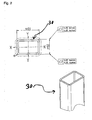
- the bridging elements 30 are executed in the embodiment of the invention shown in the drawing as hollow sections with a substantially rectangular cross-section.
- Opposite walls, one of which is applied to the outer boundary surface 14 of the Torblattelements 10 and the other facing away from the door to be closed with the door space, are penetrated by holes 32 which lie on a perpendicular to the walls straight lines, so that the holes 32 can be penetrated by screws.
- the bore 32 in the wall facing away from the space to be fired is designed with a larger diameter than the bore 32 in the wall to be applied to the outer boundary surface 14 of the door leaf element 10.
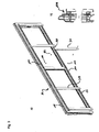
- Fig. 3 illustrated embodiment of the invention differs essentially by the in the Fig. 1 and 2 illustrated embodiment that the bridging elements 30 are slidably secured to the transverse struts 16 of the door leaf element 10.
- 10 guide elements 100 are attached to the cross struts 16 of the door leaf element.
- the guide elements 100 are designed in the form of U-profiles with a voltage applied to the cross struts 16 connecting leg and two extending from opposite edges of the connecting leg in perpendicular planes extending outer legs. The edges of the outer leg facing away from the connecting leg are bent towards one another, so that the U-profile forms a closed chamber, with the exception of a slot formed between the edges of the outer leg facing away from the connecting leg, as is particularly clear in FIG Fig. 3b ) is recognizable.
- Self-tapping screws 110 are provided for fastening the guide elements 100 to the cross struts 16, which pass through holes in the connecting leg, wherein the holes are dimensioned so that a screw head rests against the material region adjacent to the holes.
- bridging elements 30 For fixing the bridging elements 30 to the guide elements 100, threaded bolts 120 are provided, which pass through holes in the bridging elements 30 and are screwed into shaped pieces 122. The fittings 122 are received in the channel formed in the guide member. With the screws 120 loosened, the bridging elements 30 can be guided by those in the channels in the guide elements 100 recorded fittings 21 are moved along the guide elements 100. The bridging elements 30 can be locked by tightening the bolts 120 at the desired location. When tightening the bolts 120, the shaped pieces 122 are applied to the mutually bent edges of the outer legs of the guide elements 100, resulting in a non-positive fixing of the bridging elements 30 with respect to the guide elements 100.
- gates according to the invention can be designed with so-called sandwich panels, in which a foam core is accommodated between two metal shells.
- the invention can also be used profitably in so-called tilt gates with integral door leaves.
Landscapes
- Engineering & Computer Science (AREA)
- Civil Engineering (AREA)
- Structural Engineering (AREA)
- Wing Frames And Configurations (AREA)
Priority Applications (1)
| Application Number | Priority Date | Filing Date | Title |
|---|---|---|---|
| PL12006514T PL2592208T3 (pl) | 2011-11-08 | 2012-09-17 | Brama |
Applications Claiming Priority (1)
| Application Number | Priority Date | Filing Date | Title |
|---|---|---|---|
| DE202011107637U DE202011107637U1 (de) | 2011-11-08 | 2011-11-08 | Tor |
Publications (3)
| Publication Number | Publication Date |
|---|---|
| EP2592208A2 true EP2592208A2 (fr) | 2013-05-15 |
| EP2592208A3 EP2592208A3 (fr) | 2016-10-26 |
| EP2592208B1 EP2592208B1 (fr) | 2019-12-04 |
Family
ID=45557693
Family Applications (1)
| Application Number | Title | Priority Date | Filing Date |
|---|---|---|---|
| EP12006514.9A Active EP2592208B1 (fr) | 2011-11-08 | 2012-09-17 | Porte |
Country Status (3)
| Country | Link |
|---|---|
| EP (1) | EP2592208B1 (fr) |
| DE (1) | DE202011107637U1 (fr) |
| PL (1) | PL2592208T3 (fr) |
Citations (1)
| Publication number | Priority date | Publication date | Assignee | Title |
|---|---|---|---|---|
| DE102008028678A1 (de) | 2008-06-17 | 2009-12-24 | Hörmann KG Brockhagen | Tor |
Family Cites Families (2)
| Publication number | Priority date | Publication date | Assignee | Title |
|---|---|---|---|---|
| DE102005023348B3 (de) * | 2005-05-17 | 2007-01-04 | Novoferm Gmbh | Sektionaltor |
| US20090223131A1 (en) * | 2008-03-05 | 2009-09-10 | Wiese Paul A | Steel frame wood panel garage door |
-
2011
- 2011-11-08 DE DE202011107637U patent/DE202011107637U1/de not_active Expired - Lifetime
-
2012
- 2012-09-17 EP EP12006514.9A patent/EP2592208B1/fr active Active
- 2012-09-17 PL PL12006514T patent/PL2592208T3/pl unknown
Patent Citations (1)
| Publication number | Priority date | Publication date | Assignee | Title |
|---|---|---|---|---|
| DE102008028678A1 (de) | 2008-06-17 | 2009-12-24 | Hörmann KG Brockhagen | Tor |
Also Published As
| Publication number | Publication date |
|---|---|
| EP2592208B1 (fr) | 2019-12-04 |
| PL2592208T3 (pl) | 2020-05-18 |
| DE202011107637U1 (de) | 2011-12-29 |
| EP2592208A3 (fr) | 2016-10-26 |
Similar Documents
| Publication | Publication Date | Title |
|---|---|---|
| DE3540385C2 (fr) | ||
| WO1993002268A1 (fr) | Cloison ignifuge en verre | |
| EP2666948B1 (fr) | Agencement de cadre pour un panneau de porte sectionnelle | |
| DE102009023883A1 (de) | Fassadenelement | |
| CH665679A5 (de) | Tuer oder tor mit wenigstens einem isolierten fluegel, insbesondere brandschutztor. | |
| EP1070820B1 (fr) | Fenêtre | |
| DE102021001084B3 (de) | Leibungsverkleidung für Öffnungen in Wänden von Gebäuden, mit in und/oder an diesen Öffnungen angeordneten Rahmen von Fenstern oder Türen | |
| DE19744832C2 (de) | Anordnung für den Einbau eines Fensterrahmens | |
| DE19912900C1 (de) | Verkleidung für eine Wand- oder Dachfläche | |
| EP3293336B1 (fr) | Rail de retenue pour un balcon français ainsi que dispositif et système de retenue associés | |
| DE3012941A1 (de) | Fenster | |
| EP2592208B1 (fr) | Porte | |
| EP0010180B1 (fr) | Petits-bois d'une fenêtre à petits-bois | |
| EP0247356B1 (fr) | Vitrage pour des serres, jardins d'hiver ou similaires et vitres utilisables pour cela | |
| DE102020006840A1 (de) | Fenster- oder Türrahmen mit verschiebbaren Klemmleisten und aufgebrachter Dichtschicht | |
| AT510431B1 (de) | Blindzarge | |
| DE1658785A1 (de) | Elementtrennwaende | |
| DE10011576A1 (de) | Fenster- oder Türrahmen für Container o. dgl. | |
| EP1980702B1 (fr) | Construction de cadre pour fenêtres et/ou portes | |
| DE29906739U1 (de) | Aufhängevorrichtung für ein verschiebbares Schließelement, insbesondere einen Schiebeladen, ein Schiebefenster, eine Schiebewand oder -tür, und eine Zwischenschiene hierfür | |
| DE2642746A1 (de) | Aus kunststoffschaum mit eingelagerten metallenen hohlprofilen bestehender rahmen fuer fenster | |
| AT515044B1 (de) | Verkleidungselement und Verkleidungssystem | |
| DE202025100919U1 (de) | Vorrichtung zur Abdeckung eines Schiebeflügels, Falt-Schiebeflügels oder verschiebbaren Hebe-Schiebeflügels eines Fensters oder einer Tür | |
| EP4325017A1 (fr) | Profilé isolant pour relier deux éléments profilés pour la réalisation d'un profilé isolé thermiquement et un tel profilé | |
| DE29811577U1 (de) | Wandkasten für Gebäudeaußenmauern |
Legal Events
| Date | Code | Title | Description |
|---|---|---|---|
| PUAI | Public reference made under article 153(3) epc to a published international application that has entered the european phase |
Free format text: ORIGINAL CODE: 0009012 |
|
| 17P | Request for examination filed |
Effective date: 20120917 |
|
| AK | Designated contracting states |
Kind code of ref document: A2 Designated state(s): AL AT BE BG CH CY CZ DE DK EE ES FI FR GB GR HR HU IE IS IT LI LT LU LV MC MK MT NL NO PL PT RO RS SE SI SK SM TR |
|
| AX | Request for extension of the european patent |
Extension state: BA ME |
|
| PUAL | Search report despatched |
Free format text: ORIGINAL CODE: 0009013 |
|
| AK | Designated contracting states |
Kind code of ref document: A3 Designated state(s): AL AT BE BG CH CY CZ DE DK EE ES FI FR GB GR HR HU IE IS IT LI LT LU LV MC MK MT NL NO PL PT RO RS SE SI SK SM TR |
|
| AX | Request for extension of the european patent |
Extension state: BA ME |
|
| RIC1 | Information provided on ipc code assigned before grant |
Ipc: E06B 3/48 20060101AFI20160919BHEP |
|
| STAA | Information on the status of an ep patent application or granted ep patent |
Free format text: STATUS: EXAMINATION IS IN PROGRESS |
|
| 17Q | First examination report despatched |
Effective date: 20190329 |
|
| GRAP | Despatch of communication of intention to grant a patent |
Free format text: ORIGINAL CODE: EPIDOSNIGR1 |
|
| STAA | Information on the status of an ep patent application or granted ep patent |
Free format text: STATUS: GRANT OF PATENT IS INTENDED |
|
| INTG | Intention to grant announced |
Effective date: 20190829 |
|
| GRAS | Grant fee paid |
Free format text: ORIGINAL CODE: EPIDOSNIGR3 |
|
| GRAA | (expected) grant |
Free format text: ORIGINAL CODE: 0009210 |
|
| STAA | Information on the status of an ep patent application or granted ep patent |
Free format text: STATUS: THE PATENT HAS BEEN GRANTED |
|
| AK | Designated contracting states |
Kind code of ref document: B1 Designated state(s): AL AT BE BG CH CY CZ DE DK EE ES FI FR GB GR HR HU IE IS IT LI LT LU LV MC MK MT NL NO PL PT RO RS SE SI SK SM TR |
|
| REG | Reference to a national code |
Ref country code: GB Ref legal event code: FG4D Free format text: NOT ENGLISH |
|
| REG | Reference to a national code |
Ref country code: CH Ref legal event code: EP |
|
| REG | Reference to a national code |
Ref country code: AT Ref legal event code: REF Ref document number: 1209615 Country of ref document: AT Kind code of ref document: T Effective date: 20191215 |
|
| REG | Reference to a national code |
Ref country code: DE Ref legal event code: R096 Ref document number: 502012015576 Country of ref document: DE |
|
| REG | Reference to a national code |
Ref country code: IE Ref legal event code: FG4D Free format text: LANGUAGE OF EP DOCUMENT: GERMAN |
|
| REG | Reference to a national code |
Ref country code: SE Ref legal event code: TRGR |
|
| REG | Reference to a national code |
Ref country code: NL Ref legal event code: FP |
|
| REG | Reference to a national code |
Ref country code: LT Ref legal event code: MG4D |
|
| PG25 | Lapsed in a contracting state [announced via postgrant information from national office to epo] |
Ref country code: ES Free format text: LAPSE BECAUSE OF FAILURE TO SUBMIT A TRANSLATION OF THE DESCRIPTION OR TO PAY THE FEE WITHIN THE PRESCRIBED TIME-LIMIT Effective date: 20191204 Ref country code: LV Free format text: LAPSE BECAUSE OF FAILURE TO SUBMIT A TRANSLATION OF THE DESCRIPTION OR TO PAY THE FEE WITHIN THE PRESCRIBED TIME-LIMIT Effective date: 20191204 Ref country code: FI Free format text: LAPSE BECAUSE OF FAILURE TO SUBMIT A TRANSLATION OF THE DESCRIPTION OR TO PAY THE FEE WITHIN THE PRESCRIBED TIME-LIMIT Effective date: 20191204 Ref country code: BG Free format text: LAPSE BECAUSE OF FAILURE TO SUBMIT A TRANSLATION OF THE DESCRIPTION OR TO PAY THE FEE WITHIN THE PRESCRIBED TIME-LIMIT Effective date: 20200304 Ref country code: GR Free format text: LAPSE BECAUSE OF FAILURE TO SUBMIT A TRANSLATION OF THE DESCRIPTION OR TO PAY THE FEE WITHIN THE PRESCRIBED TIME-LIMIT Effective date: 20200305 Ref country code: NO Free format text: LAPSE BECAUSE OF FAILURE TO SUBMIT A TRANSLATION OF THE DESCRIPTION OR TO PAY THE FEE WITHIN THE PRESCRIBED TIME-LIMIT Effective date: 20200304 Ref country code: LT Free format text: LAPSE BECAUSE OF FAILURE TO SUBMIT A TRANSLATION OF THE DESCRIPTION OR TO PAY THE FEE WITHIN THE PRESCRIBED TIME-LIMIT Effective date: 20191204 |
|
| PG25 | Lapsed in a contracting state [announced via postgrant information from national office to epo] |
Ref country code: HR Free format text: LAPSE BECAUSE OF FAILURE TO SUBMIT A TRANSLATION OF THE DESCRIPTION OR TO PAY THE FEE WITHIN THE PRESCRIBED TIME-LIMIT Effective date: 20191204 Ref country code: RS Free format text: LAPSE BECAUSE OF FAILURE TO SUBMIT A TRANSLATION OF THE DESCRIPTION OR TO PAY THE FEE WITHIN THE PRESCRIBED TIME-LIMIT Effective date: 20191204 |
|
| PG25 | Lapsed in a contracting state [announced via postgrant information from national office to epo] |
Ref country code: AL Free format text: LAPSE BECAUSE OF FAILURE TO SUBMIT A TRANSLATION OF THE DESCRIPTION OR TO PAY THE FEE WITHIN THE PRESCRIBED TIME-LIMIT Effective date: 20191204 |
|
| PG25 | Lapsed in a contracting state [announced via postgrant information from national office to epo] |
Ref country code: EE Free format text: LAPSE BECAUSE OF FAILURE TO SUBMIT A TRANSLATION OF THE DESCRIPTION OR TO PAY THE FEE WITHIN THE PRESCRIBED TIME-LIMIT Effective date: 20191204 Ref country code: CZ Free format text: LAPSE BECAUSE OF FAILURE TO SUBMIT A TRANSLATION OF THE DESCRIPTION OR TO PAY THE FEE WITHIN THE PRESCRIBED TIME-LIMIT Effective date: 20191204 Ref country code: RO Free format text: LAPSE BECAUSE OF FAILURE TO SUBMIT A TRANSLATION OF THE DESCRIPTION OR TO PAY THE FEE WITHIN THE PRESCRIBED TIME-LIMIT Effective date: 20191204 Ref country code: PT Free format text: LAPSE BECAUSE OF FAILURE TO SUBMIT A TRANSLATION OF THE DESCRIPTION OR TO PAY THE FEE WITHIN THE PRESCRIBED TIME-LIMIT Effective date: 20200429 |
|
| PG25 | Lapsed in a contracting state [announced via postgrant information from national office to epo] |
Ref country code: SM Free format text: LAPSE BECAUSE OF FAILURE TO SUBMIT A TRANSLATION OF THE DESCRIPTION OR TO PAY THE FEE WITHIN THE PRESCRIBED TIME-LIMIT Effective date: 20191204 Ref country code: IS Free format text: LAPSE BECAUSE OF FAILURE TO SUBMIT A TRANSLATION OF THE DESCRIPTION OR TO PAY THE FEE WITHIN THE PRESCRIBED TIME-LIMIT Effective date: 20200404 Ref country code: SK Free format text: LAPSE BECAUSE OF FAILURE TO SUBMIT A TRANSLATION OF THE DESCRIPTION OR TO PAY THE FEE WITHIN THE PRESCRIBED TIME-LIMIT Effective date: 20191204 |
|
| REG | Reference to a national code |
Ref country code: DE Ref legal event code: R097 Ref document number: 502012015576 Country of ref document: DE |
|
| PLBE | No opposition filed within time limit |
Free format text: ORIGINAL CODE: 0009261 |
|
| STAA | Information on the status of an ep patent application or granted ep patent |
Free format text: STATUS: NO OPPOSITION FILED WITHIN TIME LIMIT |
|
| PG25 | Lapsed in a contracting state [announced via postgrant information from national office to epo] |
Ref country code: DK Free format text: LAPSE BECAUSE OF FAILURE TO SUBMIT A TRANSLATION OF THE DESCRIPTION OR TO PAY THE FEE WITHIN THE PRESCRIBED TIME-LIMIT Effective date: 20191204 |
|
| 26N | No opposition filed |
Effective date: 20200907 |
|
| PG25 | Lapsed in a contracting state [announced via postgrant information from national office to epo] |
Ref country code: SI Free format text: LAPSE BECAUSE OF FAILURE TO SUBMIT A TRANSLATION OF THE DESCRIPTION OR TO PAY THE FEE WITHIN THE PRESCRIBED TIME-LIMIT Effective date: 20191204 |
|
| PG25 | Lapsed in a contracting state [announced via postgrant information from national office to epo] |
Ref country code: IT Free format text: LAPSE BECAUSE OF FAILURE TO SUBMIT A TRANSLATION OF THE DESCRIPTION OR TO PAY THE FEE WITHIN THE PRESCRIBED TIME-LIMIT Effective date: 20191204 |
|
| PG25 | Lapsed in a contracting state [announced via postgrant information from national office to epo] |
Ref country code: MC Free format text: LAPSE BECAUSE OF FAILURE TO SUBMIT A TRANSLATION OF THE DESCRIPTION OR TO PAY THE FEE WITHIN THE PRESCRIBED TIME-LIMIT Effective date: 20191204 |
|
| REG | Reference to a national code |
Ref country code: CH Ref legal event code: PL |
|
| GBPC | Gb: european patent ceased through non-payment of renewal fee |
Effective date: 20200917 |
|
| REG | Reference to a national code |
Ref country code: BE Ref legal event code: MM Effective date: 20200930 |
|
| PG25 | Lapsed in a contracting state [announced via postgrant information from national office to epo] |
Ref country code: LU Free format text: LAPSE BECAUSE OF NON-PAYMENT OF DUE FEES Effective date: 20200917 |
|
| PG25 | Lapsed in a contracting state [announced via postgrant information from national office to epo] |
Ref country code: FR Free format text: LAPSE BECAUSE OF NON-PAYMENT OF DUE FEES Effective date: 20200930 |
|
| PG25 | Lapsed in a contracting state [announced via postgrant information from national office to epo] |
Ref country code: CH Free format text: LAPSE BECAUSE OF NON-PAYMENT OF DUE FEES Effective date: 20200930 Ref country code: BE Free format text: LAPSE BECAUSE OF NON-PAYMENT OF DUE FEES Effective date: 20200930 Ref country code: GB Free format text: LAPSE BECAUSE OF NON-PAYMENT OF DUE FEES Effective date: 20200917 Ref country code: LI Free format text: LAPSE BECAUSE OF NON-PAYMENT OF DUE FEES Effective date: 20200930 Ref country code: IE Free format text: LAPSE BECAUSE OF NON-PAYMENT OF DUE FEES Effective date: 20200917 |
|
| REG | Reference to a national code |
Ref country code: AT Ref legal event code: MM01 Ref document number: 1209615 Country of ref document: AT Kind code of ref document: T Effective date: 20200917 |
|
| PGFP | Annual fee paid to national office [announced via postgrant information from national office to epo] |
Ref country code: SE Payment date: 20210929 Year of fee payment: 10 |
|
| PG25 | Lapsed in a contracting state [announced via postgrant information from national office to epo] |
Ref country code: AT Free format text: LAPSE BECAUSE OF NON-PAYMENT OF DUE FEES Effective date: 20200917 |
|
| PG25 | Lapsed in a contracting state [announced via postgrant information from national office to epo] |
Ref country code: TR Free format text: LAPSE BECAUSE OF FAILURE TO SUBMIT A TRANSLATION OF THE DESCRIPTION OR TO PAY THE FEE WITHIN THE PRESCRIBED TIME-LIMIT Effective date: 20191204 Ref country code: MT Free format text: LAPSE BECAUSE OF FAILURE TO SUBMIT A TRANSLATION OF THE DESCRIPTION OR TO PAY THE FEE WITHIN THE PRESCRIBED TIME-LIMIT Effective date: 20191204 Ref country code: CY Free format text: LAPSE BECAUSE OF FAILURE TO SUBMIT A TRANSLATION OF THE DESCRIPTION OR TO PAY THE FEE WITHIN THE PRESCRIBED TIME-LIMIT Effective date: 20191204 |
|
| PG25 | Lapsed in a contracting state [announced via postgrant information from national office to epo] |
Ref country code: MK Free format text: LAPSE BECAUSE OF FAILURE TO SUBMIT A TRANSLATION OF THE DESCRIPTION OR TO PAY THE FEE WITHIN THE PRESCRIBED TIME-LIMIT Effective date: 20191204 |
|
| REG | Reference to a national code |
Ref country code: SE Ref legal event code: EUG |
|
| P01 | Opt-out of the competence of the unified patent court (upc) registered |
Effective date: 20230316 |
|
| PG25 | Lapsed in a contracting state [announced via postgrant information from national office to epo] |
Ref country code: SE Free format text: LAPSE BECAUSE OF NON-PAYMENT OF DUE FEES Effective date: 20220918 |
|
| PGFP | Annual fee paid to national office [announced via postgrant information from national office to epo] |
Ref country code: DE Payment date: 20250919 Year of fee payment: 14 |
|
| PGFP | Annual fee paid to national office [announced via postgrant information from national office to epo] |
Ref country code: PL Payment date: 20250905 Year of fee payment: 14 Ref country code: NL Payment date: 20250922 Year of fee payment: 14 |