EP2666948B1 - Agencement de cadre pour un panneau de porte sectionnelle - Google Patents
Agencement de cadre pour un panneau de porte sectionnelle Download PDFInfo
- Publication number
- EP2666948B1 EP2666948B1 EP13002491.2A EP13002491A EP2666948B1 EP 2666948 B1 EP2666948 B1 EP 2666948B1 EP 13002491 A EP13002491 A EP 13002491A EP 2666948 B1 EP2666948 B1 EP 2666948B1
- Authority
- EP
- European Patent Office
- Prior art keywords
- profile
- sectional door
- groove
- door according
- frame
- Prior art date
- Legal status (The legal status is an assumption and is not a legal conclusion. Google has not performed a legal analysis and makes no representation as to the accuracy of the status listed.)
- Active
Links
Images


Classifications
-
- E—FIXED CONSTRUCTIONS
- E06—DOORS, WINDOWS, SHUTTERS, OR ROLLER BLINDS IN GENERAL; LADDERS
- E06B—FIXED OR MOVABLE CLOSURES FOR OPENINGS IN BUILDINGS, VEHICLES, FENCES OR LIKE ENCLOSURES IN GENERAL, e.g. DOORS, WINDOWS, BLINDS, GATES
- E06B3/00—Window sashes, door leaves, or like elements for closing wall or like openings; Layout of fixed or moving closures, e.g. windows in wall or like openings; Features of rigidly-mounted outer frames relating to the mounting of wing frames
- E06B3/04—Wing frames not characterised by the manner of movement
- E06B3/263—Frames with special provision for insulation
- E06B3/26301—Frames with special provision for insulation with prefabricated insulating strips between two metal section members
- E06B3/26303—Frames with special provision for insulation with prefabricated insulating strips between two metal section members with thin strips, e.g. defining a hollow space between the metal section members
-
- E—FIXED CONSTRUCTIONS
- E06—DOORS, WINDOWS, SHUTTERS, OR ROLLER BLINDS IN GENERAL; LADDERS
- E06B—FIXED OR MOVABLE CLOSURES FOR OPENINGS IN BUILDINGS, VEHICLES, FENCES OR LIKE ENCLOSURES IN GENERAL, e.g. DOORS, WINDOWS, BLINDS, GATES
- E06B3/00—Window sashes, door leaves, or like elements for closing wall or like openings; Layout of fixed or moving closures, e.g. windows in wall or like openings; Features of rigidly-mounted outer frames relating to the mounting of wing frames
- E06B3/54—Fixing of glass panes or like plates
- E06B3/58—Fixing of glass panes or like plates by means of borders, cleats, or the like
- E06B3/5807—Fixing of glass panes or like plates by means of borders, cleats, or the like not adjustable
- E06B3/5821—Fixing of glass panes or like plates by means of borders, cleats, or the like not adjustable hooked on or in the frame member, fixed by clips or otherwise elastically fixed
-
- E—FIXED CONSTRUCTIONS
- E06—DOORS, WINDOWS, SHUTTERS, OR ROLLER BLINDS IN GENERAL; LADDERS
- E06B—FIXED OR MOVABLE CLOSURES FOR OPENINGS IN BUILDINGS, VEHICLES, FENCES OR LIKE ENCLOSURES IN GENERAL, e.g. DOORS, WINDOWS, BLINDS, GATES
- E06B3/00—Window sashes, door leaves, or like elements for closing wall or like openings; Layout of fixed or moving closures, e.g. windows in wall or like openings; Features of rigidly-mounted outer frames relating to the mounting of wing frames
- E06B3/68—Window bars
-
- E—FIXED CONSTRUCTIONS
- E06—DOORS, WINDOWS, SHUTTERS, OR ROLLER BLINDS IN GENERAL; LADDERS
- E06B—FIXED OR MOVABLE CLOSURES FOR OPENINGS IN BUILDINGS, VEHICLES, FENCES OR LIKE ENCLOSURES IN GENERAL, e.g. DOORS, WINDOWS, BLINDS, GATES
- E06B3/00—Window sashes, door leaves, or like elements for closing wall or like openings; Layout of fixed or moving closures, e.g. windows in wall or like openings; Features of rigidly-mounted outer frames relating to the mounting of wing frames
- E06B3/96—Corner joints or edge joints for windows, doors, or the like frames or wings
- E06B3/9636—Corner joints or edge joints for windows, doors, or the like frames or wings for frame members having longitudinal screw receiving channels
-
- E—FIXED CONSTRUCTIONS
- E06—DOORS, WINDOWS, SHUTTERS, OR ROLLER BLINDS IN GENERAL; LADDERS
- E06B—FIXED OR MOVABLE CLOSURES FOR OPENINGS IN BUILDINGS, VEHICLES, FENCES OR LIKE ENCLOSURES IN GENERAL, e.g. DOORS, WINDOWS, BLINDS, GATES
- E06B3/00—Window sashes, door leaves, or like elements for closing wall or like openings; Layout of fixed or moving closures, e.g. windows in wall or like openings; Features of rigidly-mounted outer frames relating to the mounting of wing frames
- E06B3/04—Wing frames not characterised by the manner of movement
- E06B3/263—Frames with special provision for insulation
- E06B2003/26349—Details of insulating strips
- E06B2003/2635—Specific form characteristics
- E06B2003/26358—Specific form characteristics stepped or undulated
-
- E—FIXED CONSTRUCTIONS
- E06—DOORS, WINDOWS, SHUTTERS, OR ROLLER BLINDS IN GENERAL; LADDERS
- E06B—FIXED OR MOVABLE CLOSURES FOR OPENINGS IN BUILDINGS, VEHICLES, FENCES OR LIKE ENCLOSURES IN GENERAL, e.g. DOORS, WINDOWS, BLINDS, GATES
- E06B3/00—Window sashes, door leaves, or like elements for closing wall or like openings; Layout of fixed or moving closures, e.g. windows in wall or like openings; Features of rigidly-mounted outer frames relating to the mounting of wing frames
- E06B3/04—Wing frames not characterised by the manner of movement
- E06B3/263—Frames with special provision for insulation
- E06B2003/26349—Details of insulating strips
- E06B2003/2635—Specific form characteristics
- E06B2003/26359—Specific form characteristics making flush mounting with neighbouring metal section members possible
-
- E—FIXED CONSTRUCTIONS
- E06—DOORS, WINDOWS, SHUTTERS, OR ROLLER BLINDS IN GENERAL; LADDERS
- E06B—FIXED OR MOVABLE CLOSURES FOR OPENINGS IN BUILDINGS, VEHICLES, FENCES OR LIKE ENCLOSURES IN GENERAL, e.g. DOORS, WINDOWS, BLINDS, GATES
- E06B3/00—Window sashes, door leaves, or like elements for closing wall or like openings; Layout of fixed or moving closures, e.g. windows in wall or like openings; Features of rigidly-mounted outer frames relating to the mounting of wing frames
- E06B3/04—Wing frames not characterised by the manner of movement
- E06B3/263—Frames with special provision for insulation
- E06B2003/26349—Details of insulating strips
- E06B2003/2635—Specific form characteristics
- E06B2003/26361—Openings, incisions or indents
-
- E—FIXED CONSTRUCTIONS
- E06—DOORS, WINDOWS, SHUTTERS, OR ROLLER BLINDS IN GENERAL; LADDERS
- E06B—FIXED OR MOVABLE CLOSURES FOR OPENINGS IN BUILDINGS, VEHICLES, FENCES OR LIKE ENCLOSURES IN GENERAL, e.g. DOORS, WINDOWS, BLINDS, GATES
- E06B3/00—Window sashes, door leaves, or like elements for closing wall or like openings; Layout of fixed or moving closures, e.g. windows in wall or like openings; Features of rigidly-mounted outer frames relating to the mounting of wing frames
- E06B3/04—Wing frames not characterised by the manner of movement
- E06B3/263—Frames with special provision for insulation
- E06B2003/26349—Details of insulating strips
- E06B2003/2635—Specific form characteristics
- E06B2003/26363—Screw channels
-
- E—FIXED CONSTRUCTIONS
- E06—DOORS, WINDOWS, SHUTTERS, OR ROLLER BLINDS IN GENERAL; LADDERS
- E06B—FIXED OR MOVABLE CLOSURES FOR OPENINGS IN BUILDINGS, VEHICLES, FENCES OR LIKE ENCLOSURES IN GENERAL, e.g. DOORS, WINDOWS, BLINDS, GATES
- E06B3/00—Window sashes, door leaves, or like elements for closing wall or like openings; Layout of fixed or moving closures, e.g. windows in wall or like openings; Features of rigidly-mounted outer frames relating to the mounting of wing frames
- E06B3/04—Wing frames not characterised by the manner of movement
- E06B3/263—Frames with special provision for insulation
- E06B2003/26349—Details of insulating strips
- E06B2003/26369—Specific material characteristics
- E06B2003/2637—Specific material characteristics reinforced
-
- E—FIXED CONSTRUCTIONS
- E06—DOORS, WINDOWS, SHUTTERS, OR ROLLER BLINDS IN GENERAL; LADDERS
- E06B—FIXED OR MOVABLE CLOSURES FOR OPENINGS IN BUILDINGS, VEHICLES, FENCES OR LIKE ENCLOSURES IN GENERAL, e.g. DOORS, WINDOWS, BLINDS, GATES
- E06B3/00—Window sashes, door leaves, or like elements for closing wall or like openings; Layout of fixed or moving closures, e.g. windows in wall or like openings; Features of rigidly-mounted outer frames relating to the mounting of wing frames
- E06B3/04—Wing frames not characterised by the manner of movement
- E06B3/263—Frames with special provision for insulation
- E06B2003/26349—Details of insulating strips
- E06B2003/26387—Performing extra functions
-
- E—FIXED CONSTRUCTIONS
- E06—DOORS, WINDOWS, SHUTTERS, OR ROLLER BLINDS IN GENERAL; LADDERS
- E06B—FIXED OR MOVABLE CLOSURES FOR OPENINGS IN BUILDINGS, VEHICLES, FENCES OR LIKE ENCLOSURES IN GENERAL, e.g. DOORS, WINDOWS, BLINDS, GATES
- E06B3/00—Window sashes, door leaves, or like elements for closing wall or like openings; Layout of fixed or moving closures, e.g. windows in wall or like openings; Features of rigidly-mounted outer frames relating to the mounting of wing frames
- E06B3/04—Wing frames not characterised by the manner of movement
- E06B3/263—Frames with special provision for insulation
- E06B2003/26392—Glazing bars
-
- E—FIXED CONSTRUCTIONS
- E06—DOORS, WINDOWS, SHUTTERS, OR ROLLER BLINDS IN GENERAL; LADDERS
- E06B—FIXED OR MOVABLE CLOSURES FOR OPENINGS IN BUILDINGS, VEHICLES, FENCES OR LIKE ENCLOSURES IN GENERAL, e.g. DOORS, WINDOWS, BLINDS, GATES
- E06B3/00—Window sashes, door leaves, or like elements for closing wall or like openings; Layout of fixed or moving closures, e.g. windows in wall or like openings; Features of rigidly-mounted outer frames relating to the mounting of wing frames
- E06B3/32—Arrangements of wings characterised by the manner of movement; Arrangements of movable wings in openings; Features of wings or frames relating solely to the manner of movement of the wing
- E06B3/48—Wings connected at their edges, e.g. foldable wings
- E06B3/485—Sectional doors
Definitions
- the invention relates to a sectional door according to the preamble of patent claim 1.
- Sectional doors are used to close garage and hall openings. They have a door leaf movable along a guide rail arrangement between an open position and a closed position.
- the door leaf consists of a plurality of respect. With respect to the direction of movement extending hinge axes against each other pivotable Se Erasmusaltorpaneelen.
- This Torblattkonstrutation allows an opening and closing movement along the guide rail assembly without pivoting of the door leaf in the space thus to be closed off the area because the Torblattpaneele rest along an arcuate guide rail area and can be tilted against each other.
- the guide rails are regular a first guide rail section running rectilinearly and in the direction of gravity, a second guide rail section running in a straight line and substantially in the horizontal direction, and a curved guide rail section interconnecting the two linearly extending guide rail sections.
- the horizontal guide rail area is usually arranged overhead, so that the Se Erasmusaltorblatt can be arranged in the open position above the head approximately in a horizontal plane, while it is arranged in the closed position approximately in a vertical plane.
- the panels of such door leaves can be designed as so-called sandwich constructions in which an insulating foam core is accommodated between two metal shells.
- Corresponding Sedgingaltorblattpaneele are, for example, in the EP 0 370 376 described. The disclosure of this document is hereby expressly incorporated into this description with regard to the construction of sectional aluminum panels, in particular with regard to their edge profiles.
- the individual frame profiles are connected to one another via two plastic strips, that is to say connecting elements made of a thermally insulating material.
- two transparent discs having filling can be used. This filling is usually on a seal assembly on a positioning web of the outer profile and can be locked there with the help of a filling engaging under holding device.
- the individual frame profiles are common, as well as the Holding device, to obtain a satisfactory overall stability made of a metallic material, esp. Executed as aluminum extruded profiles.
- insulating frame arrangements for doors and windows are described.
- EP 1 256 685 A2 a folding door is described with two or more mutually hinged Torfeldern, each of which has a support frame, which is made of frame profiles, wherein on the outside of the door trim strips are provided, which are clipped on at least one held on the frame profile insulating insert, and a the clear space of the support frame covering filling is held on the support frame.
- the invention has for its object to provide a sectional door with improved thermal separation between the interior and exterior.
- the invention is based on the knowledge that the problems observed in the prior art are essentially due to the heat or cold bridges provided by the holding device.
- a direct heat transfer between the outer and the inner profile of the frame assembly is prevented via the holding device, because the holding device can be coupled by avoiding simultaneous contact with two profiles of the frame assembly on the coupling device to the connecting device of thermally insulating material.
- a satisfactory thermal separation between exterior and interior is achieved with frame arrangements according to the invention.
- the coupling device integrally with a extending between the inner and the outer profile and preferably both on the inner and on the outer profile fastened connecting element of the connecting device is formed.
- the connecting element can be made entirely of plastic together with the coupling device, for example as a plastic extruded profile.
- the depth direction of the groove extending from the groove bottom in the direction of the groove opening therefore extends approximately perpendicular to the outside or inside of the frame.
- a groove wall may be formed by the filling surface facing the boundary surface of the connecting element. If this groove wall is flush with an adjoining support surface of the groove opening facing profile, preferably the inner profile, esp. Coplanar is designed so that the insertion of the retaining strip of the holding device is favored in the groove.
- the insertion of the retaining strip in the groove can be further facilitated without affecting the holding properties, when the groove tapers, starting from the groove opening in the direction of the groove bottom in a direction approximately perpendicular to the groove wall formed by the filling facing boundary surface of the connecting element.
- the groove width can remain constant in sections, so as to secure a stable coupling of the holding device to the connecting element.
- the retaining strip can be clamped with appropriate dimensioning between retaining web and coupling groove. It has proven to be favorable in terms of a particularly stable locking of the retaining strip when between holding web and support surface is open in the direction of the coupling groove holding groove for receiving a retaining lug on the side facing away from the coupling groove of the holding device or retaining strip.
- the connecting element is positively connected to at least one profile.
- a connecting edge of the connecting element extending in the longitudinal direction of a profile is thickened and received in a connecting groove of the profile.
- the connecting element is designed cranked. It has proved to be particularly favorable when the connecting element on opposite sides of the coupling groove in each case falls away in a direction away from the filling and terminates in a respective thickened connecting edge.
- the stability of the attachment of the holding device to the coupling device of the connecting element is further improved according to the invention that the connecting element in the region of its boundary surface facing away from the coupling device at least one extending in one of the filling direction extending and designed for supporting on a support bar of a profile supporting projection.
- the connecting device has at least one further, approximately parallel to the equipped with the coupling device connecting element, preferably connected at its opposite edges, each with a profile connecting element.
- the further connecting element can be designed cranked in terms of increasing the overall stability, and it can fall off in a direction away from its each received in a holding groove, preferably hidden edges in a filling direction to a central region.
- a connection or stabilization rung of a frame produced from a frame arrangement according to the invention arranged in the region of the filling usually becomes attached to the frame assembly with suitable fastening bolts or bolts. It has proved to be particularly useful in terms of increasing the overall stability while avoiding impairment of the thermal separation, if at least one profile of a frame assembly according to the invention has a support web with an applied for applying a bolt head thereto, the filling facing away from contact surface.
- the individual profiles of the frame assembly are thermally coupled to one another not only via the connecting elements, but also via the bolt head of the fastening bolt.
- the cross-section of a corresponding bolt head is, however, regularly made so low that the heat conduction over the bolt head is negligible and can be readily accepted in view of the stability increase achieved by the installation of the bolt head on the contact surface.
- a secure fixing of the filling to the frame assembly can be achieved if at least one connecting element has a recess penetrated by the fastening bolt, wherein the bolt head continues to rest against the contact surface of the frame Abutment web of the profile is applied.
- the support web can be arranged between the connecting elements.
- the support web is formed by the support strip, which therefore has a dual function in which one of the filling facing boundary surface of the support strip for supporting the support projection of a connecting element, while a filling facing away from the boundary surface of the support strip as a contact surface for the Bolt head is used.
- At least one profile is designed as an aluminum extruded profile with integrated support web, support bar and connecting grooves.
- At least one connecting element is at least partially made of a glass fiber reinforced plastic, such as polypropylene with glass fiber reinforcement.
- a glass fiber reinforced plastic such as polypropylene with glass fiber reinforcement.
- the connecting element preferably has a tensile strength according to ISO 527 of more than 50 MPa, preferably 57 MPa or more.
- the tensile modulus of the plastic used to make the fastener according to ISO 527 may be more than 3000, in particular 4000 MPa or more.
- the plastic expediently has an elongation at break of more than 2.5%, in particular 3% or more.
- the impact strength is expediently more than 15 kJ / m 2 , in particular 18 kJ / m 2 or more.
- the thermal conductivity of the plastic used to produce the connecting element according to DIN 52612 is preferably less than 0.35 W / m ⁇ K, in particular about 0.25 W / m ⁇ K.
- the coefficient of thermal expansion in the longitudinal direction may be 2.5 to 3.8 ⁇ 10 -5 / K.
- the melting temperature according to ISO 3146 is preferably more than 120 ° C, esp. 160 ° C or more.
- the heat distortion temperature (1.8 MPa) according to DIN EN ISO 75 is 118 ° C or more.
- a frame made using a frame assembly according to the invention may comprise four frame assemblies according to the invention which circulate a filling.
- a sectional aluminous panel made therefrom may have at least one frame.
- frame assembly 10 comprises an outer boundary surface 21 of the frame assembly 10 forming profile 20, an inner boundary surface 41 of the frame assembly 10 forming profile 40, a total of 50 designated and two transparent discs 52 and 54, which are separated by a spacer 56 from each other, having a filling and a generally designated 60 holding means for holding the filling 50 to the frame assembly 10th
- the profiles 20 and 40 are executed in the embodiment of the invention shown in the drawing as extruded aluminum profiles and spaced apart in a direction perpendicular to the outer surface 21 and inner surface 41 extending direction.
- the profiles 20 and 40 are at the in Fig. 1 illustrated embodiment of the invention via a two connecting elements 80, 100 having connecting means connected to each other.
- the connecting element 80 arranged on the side of the connecting element 100 facing away from the filling 50 has an approximately perpendicular to the outer boundary surface 21 and parallel to the longitudinal axis of the profiles 20 and 40 extending central region, which increases in the direction of the filling 50 ramp areas 84 and 86th in thickened end portions 88 and 90 passes.
- the edge region 90 is received in a parallel to the longitudinal axis of the profile 20 extending lateral groove 30 of the profile 20.
- the thickened edge region 88 is received in a longitudinal groove 32 of the profile 40 which is open parallel to the longitudinal axis of the profile 40.
- the groove openings of the grooves 30 and 32 face each other.
- the filling walls 50 facing away from the groove walls 31 and 33 of the grooves 30 and 32 can be bent after insertion of the connecting element 80 in the direction of the filling 50 upwards.
- Overall, by receiving the thickened edge regions 88 and 90 in the grooves 30 and 32 of the profiles 20 and 40 ensures a positive connection between the profiles 20 and 40 via the connecting element 80.
- connection element 100 arranged on the side of the connecting element 80 facing the filling 50 is designed. It has a central region 101 which forms a boundary surface of the connecting element 100 facing the filling 50 and equipped with a coupling device 120. On both sides of the coupling device 120, the connecting element 100 drops over ramp areas 104 and 106 in the direction of thickened edge areas 108 and 110, respectively.
- the thickened edge regions 108 and 110 are received in grooves 22 and 42 of the profiles 20 and 40, respectively, which have mutually facing groove openings.
- the groove wall 24 of the groove 22 facing away from the connecting element 80 can be bent downwards in the direction of the connecting element 80 after insertion of the thickened edge region 110.
- the groove wall 44 facing away from the connecting element 80 can be bent down into the groove 42 after the thickened edge region 108 has been inserted so as to achieve a positive connection between the connecting element 100 and the edge profiles 20 and 40 arranged on both sides of the connecting element 100.
- the coupling device 120 arranged on the boundary surface 102 facing the filling 50 of the connecting element 100 is embodied in one piece with the connecting element 100 and has a bracket 124 extending approximately parallel to the boundary surface 102 of the connecting element facing the filling 50. Between the filling surface 50 facing away from the boundary surface of the bracket 124 and the filling 50 facing boundary surface 102 of the central region of the connecting element 100 is an open towards the inner profile 40 groove 122 is formed.
- the closed in the embodiment of the invention shown in the drawing groove bottom 126 of the groove 122 is the outer boundary surface 21 forming profile 20 faces.
- the groove 122 of the coupling device 120 serves to receive a retaining strip 62 of the holding device 60.
- the reception of the retaining strip 62 is promoted by the fact that the groove opening tapers in the direction of the groove bottom 126.
- the holding device 60 extends in the direction of the inner boundary surface 41 of the profile 40 approximately parallel to a coplanar to the filling 50 facing boundary surface 102 of the connecting element 100 extending support surface 46 of the profile 40. On its side facing away from the profile 20 If the bearing surface 46 in a in the direction of the filling 50 having the interior of the frame projecting retaining web 48 via.
- a groove open in the direction of the coupling groove 122 is formed, into which a retaining lug 64 of the holding device 60 can be clipped.
- the holding web 48 can be inserted into the coupling groove 122 and the holding device 60 can be pivoted overall in a direction away from the filling 50, whereby the retaining lug 64 is clipped into the retaining groove.
- the holding device 60 has on its side facing away from the holding web 48 an approximately parallel to the inner boundary surface 41 extending cover strip 66 which rests on the retaining lug 64 opposite side via two abutment protrusions 68 on the inner disc 54 of the filling 50. Due to the coplanar design of bearing surface 46 on the one hand and the filling 50 facing boundary surface 102 of the connecting device 100 on the other hand, the insertion of the holding device 60 is favored in the coupling groove 122.
- the outer boundary surface 21 forming profile 20 also has a preferably coplanar to the support surface 46 and the filling 50 facing boundary surface 28.
- the retaining web 70 serves to ensure a reliable positioning of the filling 50 with respect to the profile 20. He is a total, as well as the Connecting elements 80 and 100, made of a thermally insulating material, such as plastic. This further improves the thermal separation between the aluminum profiles 20 and 40.
- the profile 20 On the side facing away from the profile 40 of the boundary surface 28, the profile 20 is in a in the direction of the filling 50 receiving the interior of the frame extending sealing leg 27 over. This is provided on its outer disk 52 of the filling 50 facing side with a groove 26 in which a on the other hand on the outer disk 52 of the filling 50 fitting seal 29 is received.
- the inventively achievable thermal separation between the profiles 20 and 40 can also be achieved without affecting the overall stability of the arrangement, if this ratio in the range between 1: 4 and 1: 12, esp. 1: 6 and 1:10, is set.
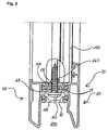
- FIG. 2 is a sectional view of the in Fig. 1 shown frame assembly 10 in the region of a connecting rung 150 between two spaced parallel to each other extending frame assemblies 10 shown.
- a screw bolt 160 is screwed into the connecting rung 150.
- the bolt 160 passes through an opening 170 in the connecting element 80 and an opening 172 in the connecting element 100.
- the bolt head 162 is located on a connecting rung 150 facing away from the boundary surface of the support strips 25 and 45 at.
- the support strips 25 and 45 thus fulfill a dual function as a support web for the bolt head 162 of the bolt 160 and as a support strip for the support projections of the connecting element 100, as particularly clearly in Fig. 2 can be seen.
- connecting rungs 150 between individual frame assemblies 10 there is a metallic connection between the profiles 20 and 40 only in the area of usually also made of metal bolts 160.
- frame assemblies 10 is on the filling 50 and the connecting rung 150 facing away from a recess 200 formed, which serves in the production of sectional door panels for receiving a projection 68 at the upper edge of a arranged under the frame assembly 10 profile 20, 40.
- a Fingerklemmschutz can be effected. That is in detail in the EP 0 370 376 explained.
- the disclosure of this document is hereby incorporated by reference into this description with respect to the achievable by receiving projections in recesses finger protection effect and the shaping of projection and recess.
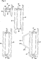
- FIG. 3 Frame assemblies 10 are shown which are provided to form a lower edge of a sectional door panel. All frame assemblies 10 have in common that they have two aluminum extrusions 20 and 40, which via connecting elements 80 and 100 are positively connected to each other, wherein in the region of the filling 50 (not shown) facing boundary surface 102 of the connecting element 100, a coupling device 120 for producing a positive connection with a designed to hold the filling 50 holding device 60 is arranged.
- FIG. 3a shown frame assembly corresponds to the frame assembly 10 according to the Fig. 1 and 2 ,
- the distance between the connecting elements 80 and 100 and the profile height of the profiles 20 and 40 are larger.
- the frame arrangements according to Fig. 3c) and 3d ) have at their lower edge a retaining groove 200 for receiving a bottom seal.
- a reinforcing element 220 is provided in the region of the inner boundary surface 41, which is placed on the boundary surface 41.
- Fig. 4a a frame arrangement is shown, which is intended to form an upper edge of Sedgingaltorpaneelen.
- FIG. 4 shown frame assemblies consisting essentially of two aluminum extruded profiles 20 and 40, of which the aluminum extruded profile 20 forms an outer boundary surface 21 of the frame assembly 10 and the aluminum extruded profile 40 an inner boundary surface 41 of the frame assembly 10.
- the profiles 20 and 40 according to Fig. 4 are, as well as the profiles (20, 40) according to Fig. 3 , via connecting elements 80 and 100 connected to each other, wherein the connecting element 80 on the filling 50 (not shown) opposite side of the connecting element 100 is disposed and on the filling 50 facing boundary surface 102 of the connecting element 100 has a coupling device 120 for producing a positive connection with associated with holding the filling 50 designed holding device 60.
- open projections 210 are formed, which can be inserted into corresponding recesses 200 in the region of the lower edge of the profiles 20 and 40 of adjacent Sekomaltorpaneele so as to bring about a desired Fingerklemmschutz für.
- the frame assemblies formed by the profiles 20 and 40 have an opening 250 which can be closed by means of a cover made of a suitable thermally insulating material, such as plastic.
- two, three or more frame assemblies 10 may be used in accordance with Fig. 1 to 4 be connected together so that they circulate a total of 50 filling.
- the frame is formed from only one frame assembly 10.
- a frame completely surrounding a filling 50 is first produced from the profiles 20 forming the outer boundary surface 21 and the profiles 40 and the connecting elements 80 and 100 forming the inner boundary surface 41. If necessary, a seal 29 and a spacer 56 are then inserted into the frame.
- the frame can be placed on the outer boundary surface 21.
- the filling 50 is then inserted into the frame prepared in this way.
- the holding device 60 is inserted into the coupling groove 122 until the projections 68 abut against the inner boundary surface 41 of the disk 54. Subsequently, the holding device 60 is pivoted in a direction away from the filling 50 until the retaining lug 64 clings into the retaining strip 62.
- the invention is not limited to the embodiments explained with reference to the drawing. Rather, it is also intended to the production of frame assemblies with only one connecting element. Furthermore, three, four or more connecting elements for producing inventive frame arrangements can be used. With appropriate design of the profiles can be dispensed with a spacer. Likewise, if necessary, can be dispensed with seals.
- the invention is not limited only in connection with sectional aluminum panels with anti-pinch measures. It can also be used on panels without such measures.
- the holding means for the filling is positively connected to a connecting element made of a thermally insulating material so as to prevent the direct metallic contact between the individual profiles of the frame assembly.
Landscapes
- Engineering & Computer Science (AREA)
- Civil Engineering (AREA)
- Structural Engineering (AREA)
- Wing Frames And Configurations (AREA)
Claims (15)
- Porte sectionnelle comportant un vantail de porte, présentant une pluralité de panneaux de porte sectionnelle susceptibles de pivoter les uns contre les autres eu égard à des axes de pivotement orientés perpendiculairement à un sens de déplacement, et un agencement de rails de guidage destiné à guider le déplacement du vantail de porte entre une position de fermeture, dans laquelle il est disposé sensiblement dans un plan vertical, et une position d'ouverture, dans laquelle il est disposé, au-dessus de la tête, dans un plan horizontal ; au moins un des panneaux de porte sectionnelle présentant une garniture intérieure (50), un dispositif de retenue (60) destiné à retenir la garniture intérieure (50), un agencement de cadre (10) destiné à produire un cadre, pour le panneau de porte sectionnelle, circonscrivant la garniture intérieure (50) et possédant un profil extérieur (20) formant la face extérieure (21) du cadre et un profil intérieur (40) formant la face intérieure (41) du cadre, les profils (20, 40) étant écartés l'un de l'autre dans un sens orienté de préférence perpendiculairement à la face extérieure et/ou à la face intérieure et étant reliés l'un à l'autre au moyen d'un dispositif de raccordement (80, 100) constitué au moins partiellement dans un matériau thermiquement isolant, ledit dispositif de raccordement (80, 100) présentant un élément de raccordement possédant au moins une surface de délimitation (102) tournée vers la garniture intérieure (50), caractérisée en ce qu'il est disposé, sur la surface de délimitation (102) de l'élément de raccordement (100) qui est tournée vers la garniture intérieure (50), un dispositif de couplage (120) servant à produire un raccordement par complémentarité de forme avec le dispositif de retenue (60) et conçu d'un seul tenant avec l'élément de raccordement (100) du dispositif de raccordement (80) qui est compris entre le profil intérieur (40) et le profil extérieur (20), et en ce que l'élément de raccordement (100) présente, sur sa surface de délimitation détournée du dispositif de couplage (120), au moins un relief d'appui (112) orienté dans un sens allant en s'éloignant de la garniture intérieure (50) et conçu pour s'appuyer sur une baguette d'appui (25, 45) d'un profil (20, 40), ledit élément de raccordement retombant, des deux côtés du dispositif de couplage (120), par le biais de sections de déclivité (104, 106), sur des sections de bord renflées (108, 110), lesquelles sections de bord renflées (108, 110) logent dans des rainures (22, 42) des profils (20, 40).
- Porte sectionnelle selon la revendication 1, caractérisée en ce que le dispositif de couplage (120) présente une rainure de couplage (122) orientée dans le sens longitudinal des profils (20, 40) et destinée à recevoir une baguette de retenue (62) du dispositif de retenue (60), ladite rainure de couplage présentant un fond de rainure (126) tourné vers un profil (20) et une ouverture de rainure tournée vers l'autre profil (40).
- Porte sectionnelle selon la revendication 2, caractérisée en ce qu'une paroi de rainure (24) est formée par le biais de la surface de délimitation (102) de l'élément de raccordement (100) qui est tournée vers la garniture intérieure (50), laquelle paroi de rainure est de préférence alignée avec une surface contiguë de support (46) du profil (40) tourné vers l'ouverture de rainure, en étant notamment coplanaire avec cette surface de support.
- Porte sectionnelle selon la revendication 3, caractérisée en ce que la surface de support (46) est contiguë à un gradin de retenue (48) orienté dans le sens longitudinal du profil (40) et faisant saillie, à partir de la surface de support (46), en direction de l'espace intérieur du cadre présentant la garniture intérieure (50).
- Porte sectionnelle selon la revendication 4, caractérisée en ce qu'il est constitué, entre le gradin de retenue (48) et la surface de support (46), une rainure de retenue ouverte en direction de la rainure de couplage (122) et destinée à recevoir un ergot de retenue (64) sur la face de la baguette de retenue (62) détournée de la rainure de couplage (122).
- Porte sectionnelle selon l'une des revendications précédentes, caractérisée en ce qu'un bord de raccordement (108, 110) de l'élément de raccordement (100), qui est orienté dans le sens longitudinal d'un profil (20, 40), est renflé et loge dans une rainure de raccordement (22, 42) d'un profil (20, 40).
- Porte sectionnelle selon la revendication 6, caractérisée en ce que l'élément de raccordement (100) retombe sur des faces opposées de la rainure de couplage (122) dans un sens respectif allant en s'éloignant de la garniture intérieure (50) et se termine par un bord de raccordement (108, 110) renflé respectif.
- Porte sectionnelle selon l'une des revendications précédentes, caractérisée en ce que le dispositif de raccordement (80, 100) présente au moins un élément de raccordement (80) supplémentaire orienté de manière sensiblement parallèle à l'élément de raccordement (100) pourvu du dispositif de couplage (120), ledit élément de raccordement supplémentaire étant de préférence relié par ses bords opposés à un profil (20, 40) respectif.
- Porte sectionnelle selon la revendication 8, caractérisée en ce que l'élément de raccordement (80) supplémentaire retombe vers une zone médiane à partir de ses bords (88, 90) logeant dans une rainure de retenue (30, 32) respective, selon un sens allant en s'éloignant de la garniture intérieure (50).
- Porte sectionnelle selon l'une des revendications précédentes, caractérisée par un boulon de fixation (160), notamment une vis, servant à la fixation d'une traverse de stabilisation (150) sur l'agencement de cadre (10), au moins un des profils (20, 40) présentant un gradin de retenue (25, 45) possédant une surface de support (46) détournée de la traverse de stabilisation (150) et dimensionnée de manière à supporter la tête du boulon (162).
- Porte sectionnelle selon la revendication 10, caractérisée en ce qu'au moins un élément de raccordement (80, 100) présente un évidement (170, 172) traversé par un boulon de fixation (160).
- Porte sectionnelle selon la revendication 10 ou 11, caractérisée en ce que le gradin de retenue (25, 45) est disposé entre les éléments de raccordement (80, 100).
- Porte sectionnelle selon l'une des revendications 10 à 12, caractérisée en ce que le gradin de retenue (25, 45) est constitué par la baguette d'appui (25, 45).
- Porte sectionnelle selon l'une des revendications précédentes, caractérisée en ce qu'au moins un profil (20, 40) est conçu sous la forme d'un profil extrudé en aluminium présentant un gradin de retenue (72), une baguette d'appui (25, 45) et des rainures de raccordement (22, 42) intégrés.
- Porte sectionnelle selon l'une des revendications précédentes, caractérisée en ce qu'au moins un élément de raccordement (80, 100) est constitué au moins en partie d'une matière plastique renforcée de fibres, notamment de polypropylène renforcé de fibres de verre.
Priority Applications (1)
| Application Number | Priority Date | Filing Date | Title |
|---|---|---|---|
| PL13002491T PL2666948T3 (pl) | 2012-05-21 | 2013-05-10 | Belka ramowa do panelu bramy segmentowej |
Applications Claiming Priority (1)
| Application Number | Priority Date | Filing Date | Title |
|---|---|---|---|
| DE102012010028A DE102012010028A1 (de) | 2012-05-21 | 2012-05-21 | Rahmenanordnung für ein sektionaltorpaneel |
Publications (2)
| Publication Number | Publication Date |
|---|---|
| EP2666948A1 EP2666948A1 (fr) | 2013-11-27 |
| EP2666948B1 true EP2666948B1 (fr) | 2018-02-21 |
Family
ID=48430425
Family Applications (1)
| Application Number | Title | Priority Date | Filing Date |
|---|---|---|---|
| EP13002491.2A Active EP2666948B1 (fr) | 2012-05-21 | 2013-05-10 | Agencement de cadre pour un panneau de porte sectionnelle |
Country Status (3)
| Country | Link |
|---|---|
| EP (1) | EP2666948B1 (fr) |
| DE (1) | DE102012010028A1 (fr) |
| PL (1) | PL2666948T3 (fr) |
Cited By (1)
| Publication number | Priority date | Publication date | Assignee | Title |
|---|---|---|---|---|
| EP4136303A1 (fr) * | 2020-04-16 | 2023-02-22 | ASSA ABLOY Entrance Systems AB | Système d'entrée |
Families Citing this family (6)
| Publication number | Priority date | Publication date | Assignee | Title |
|---|---|---|---|---|
| DE102019115718A1 (de) | 2019-06-11 | 2020-12-17 | Hörmann KG Brockhagen | Sektionaltor |
| EP4323618B1 (fr) * | 2021-04-15 | 2025-11-19 | ASSA ABLOY Entrance Systems AB | Disposition des panneaux, vantail de porte et système de porte |
| DE102022113452A1 (de) * | 2022-05-27 | 2023-11-30 | Alpha Deuren International Bv | Verbundformkörper |
| EP4283086B1 (fr) | 2022-05-27 | 2024-10-30 | Alpha Deuren International BV | Structure de cadre comme élément de panneau pour une lame de porte sectionnelle |
| DE102022113451A1 (de) | 2022-05-27 | 2023-11-30 | Alpha Deuren International Bv | Montageleiste |
| EP4299871B1 (fr) | 2022-05-27 | 2024-12-25 | Alpha Deuren International BV | Structure de cadre faisant partie d'un élément de panneau pour une lame de porte sectionnelle |
Family Cites Families (8)
| Publication number | Priority date | Publication date | Assignee | Title |
|---|---|---|---|---|
| DE3343687A1 (de) * | 1983-11-30 | 1985-06-05 | Schweizerische Aluminium Ag, Chippis | Metall-rahmenkonstruktion fuer fenster oder tueren |
| EP0370376B2 (fr) | 1988-11-25 | 1998-12-02 | Hörmann KG Brockhagen | Vantail de porte |
| DE19800130C1 (de) * | 1998-01-03 | 1999-05-20 | Hans Dieter Grotefeld | Kämpfer-Verbinder für Fenster- und Türrahmen |
| CA2421361A1 (fr) * | 2000-09-05 | 2002-03-14 | Crittall Windows Limited | Cadres de fenetres |
| AT409999B (de) * | 2001-05-11 | 2002-12-27 | Bator Schweiz Ag | Tor |
| GB0117104D0 (en) * | 2001-07-13 | 2001-09-05 | Sapa Building Systems Ltd | Window units |
| US7987633B2 (en) * | 2007-05-16 | 2011-08-02 | Alcoa Commercial Windows Llc | Construction product having a frame with multi-functional thermal break |
| FR2957965B1 (fr) * | 2010-03-29 | 2012-05-11 | Trendel Et Fils A | Porte de garage isolee |
-
2012
- 2012-05-21 DE DE102012010028A patent/DE102012010028A1/de active Pending
-
2013
- 2013-05-10 PL PL13002491T patent/PL2666948T3/pl unknown
- 2013-05-10 EP EP13002491.2A patent/EP2666948B1/fr active Active
Non-Patent Citations (1)
| Title |
|---|
| None * |
Cited By (1)
| Publication number | Priority date | Publication date | Assignee | Title |
|---|---|---|---|---|
| EP4136303A1 (fr) * | 2020-04-16 | 2023-02-22 | ASSA ABLOY Entrance Systems AB | Système d'entrée |
Also Published As
| Publication number | Publication date |
|---|---|
| DE102012010028A1 (de) | 2013-11-21 |
| EP2666948A1 (fr) | 2013-11-27 |
| PL2666948T3 (pl) | 2018-07-31 |
Similar Documents
| Publication | Publication Date | Title |
|---|---|---|
| EP2666948B1 (fr) | Agencement de cadre pour un panneau de porte sectionnelle | |
| EP3080375B2 (fr) | Dispositif destiné à fermer une ouverture dans un bâtiment | |
| DE202005004338U1 (de) | Wärmedämmleiste für einen Glasfalz | |
| DE102017100336A1 (de) | Tür, Fenster oder Fassadenelement | |
| DE19601505C1 (de) | Glasrandhalterung | |
| WO2008135071A1 (fr) | Élément destiné à la fabrication d'un battant de porte sectionnelle et cache frontal associé | |
| EP1932997A2 (fr) | Fermeture supérieure d'un système de fermeture de seuil et seuil | |
| EP2610423A2 (fr) | Porte coulissante/relevable | |
| EP2341202B1 (fr) | Protection contre les intrusions pour une porte ou une fenêtre | |
| EP3770372B1 (fr) | Coffre de réception d'un volet roulant ou d'une protection solaire et fenêtre ou porte | |
| EP1057961A2 (fr) | Seuil pour porte de maison ainsi que porte de maison | |
| WO2011067210A2 (fr) | Paroi coulissante comportant au moins deux vantaux | |
| EP0730068B1 (fr) | Lucarne | |
| DE202004000817U1 (de) | Rahmenkörper aus einem hohlen, stranggepreßten Kunststoffprofil für Fenster und Türen | |
| EP0477544B1 (fr) | Pièce de remplissage pour parcloses | |
| EP3348731B1 (fr) | Construction à poteaux-traverses | |
| DE202010013228U1 (de) | Auflageanordnung für ein Fenster, eine Tür o.dgl. | |
| EP1683940A2 (fr) | Fenêtre ou porte avec vitrage collé | |
| EP2072744B1 (fr) | Profilés dormants pour une porte coulissante relevable | |
| DE10251431A1 (de) | Haustür | |
| DE20100618U1 (de) | Rahmenprofil | |
| EP2055884B1 (fr) | Profilé rapporté pour profilé composite pour fenêtres, portes ou analogues et profilé composite doté d'un tel profilé rapporté | |
| DE102020103603B4 (de) | Hochwasserbeständiges Sektionaltor | |
| DE20009185U1 (de) | Schwellenprofil für Gebäudetüren sowie Gebäudetür | |
| EP2206873A1 (fr) | Unité d'élément mural à isolation thermique pour façades de bâtiments |
Legal Events
| Date | Code | Title | Description |
|---|---|---|---|
| PUAI | Public reference made under article 153(3) epc to a published international application that has entered the european phase |
Free format text: ORIGINAL CODE: 0009012 |
|
| 17P | Request for examination filed |
Effective date: 20130510 |
|
| AK | Designated contracting states |
Kind code of ref document: A1 Designated state(s): AL AT BE BG CH CY CZ DE DK EE ES FI FR GB GR HR HU IE IS IT LI LT LU LV MC MK MT NL NO PL PT RO RS SE SI SK SM TR |
|
| AX | Request for extension of the european patent |
Extension state: BA ME |
|
| 17Q | First examination report despatched |
Effective date: 20160520 |
|
| GRAP | Despatch of communication of intention to grant a patent |
Free format text: ORIGINAL CODE: EPIDOSNIGR1 |
|
| INTG | Intention to grant announced |
Effective date: 20171204 |
|
| GRAS | Grant fee paid |
Free format text: ORIGINAL CODE: EPIDOSNIGR3 |
|
| GRAA | (expected) grant |
Free format text: ORIGINAL CODE: 0009210 |
|
| AK | Designated contracting states |
Kind code of ref document: B1 Designated state(s): AL AT BE BG CH CY CZ DE DK EE ES FI FR GB GR HR HU IE IS IT LI LT LU LV MC MK MT NL NO PL PT RO RS SE SI SK SM TR |
|
| REG | Reference to a national code |
Ref country code: GB Ref legal event code: FG4D Free format text: NOT ENGLISH |
|
| REG | Reference to a national code |
Ref country code: CH Ref legal event code: EP |
|
| REG | Reference to a national code |
Ref country code: DE Ref legal event code: R096 Ref document number: 502013009425 Country of ref document: DE Ref country code: AT Ref legal event code: REF Ref document number: 971908 Country of ref document: AT Kind code of ref document: T Effective date: 20180315 |
|
| REG | Reference to a national code |
Ref country code: IE Ref legal event code: FG4D Free format text: LANGUAGE OF EP DOCUMENT: GERMAN |
|
| REG | Reference to a national code |
Ref country code: NL Ref legal event code: FP |
|
| REG | Reference to a national code |
Ref country code: SE Ref legal event code: TRGR |
|
| REG | Reference to a national code |
Ref country code: FR Ref legal event code: PLFP Year of fee payment: 6 |
|
| REG | Reference to a national code |
Ref country code: LT Ref legal event code: MG4D |
|
| PG25 | Lapsed in a contracting state [announced via postgrant information from national office to epo] |
Ref country code: ES Free format text: LAPSE BECAUSE OF FAILURE TO SUBMIT A TRANSLATION OF THE DESCRIPTION OR TO PAY THE FEE WITHIN THE PRESCRIBED TIME-LIMIT Effective date: 20180221 Ref country code: LT Free format text: LAPSE BECAUSE OF FAILURE TO SUBMIT A TRANSLATION OF THE DESCRIPTION OR TO PAY THE FEE WITHIN THE PRESCRIBED TIME-LIMIT Effective date: 20180221 Ref country code: CY Free format text: LAPSE BECAUSE OF FAILURE TO SUBMIT A TRANSLATION OF THE DESCRIPTION OR TO PAY THE FEE WITHIN THE PRESCRIBED TIME-LIMIT Effective date: 20180221 Ref country code: FI Free format text: LAPSE BECAUSE OF FAILURE TO SUBMIT A TRANSLATION OF THE DESCRIPTION OR TO PAY THE FEE WITHIN THE PRESCRIBED TIME-LIMIT Effective date: 20180221 Ref country code: NO Free format text: LAPSE BECAUSE OF FAILURE TO SUBMIT A TRANSLATION OF THE DESCRIPTION OR TO PAY THE FEE WITHIN THE PRESCRIBED TIME-LIMIT Effective date: 20180521 Ref country code: HR Free format text: LAPSE BECAUSE OF FAILURE TO SUBMIT A TRANSLATION OF THE DESCRIPTION OR TO PAY THE FEE WITHIN THE PRESCRIBED TIME-LIMIT Effective date: 20180221 |
|
| PG25 | Lapsed in a contracting state [announced via postgrant information from national office to epo] |
Ref country code: LV Free format text: LAPSE BECAUSE OF FAILURE TO SUBMIT A TRANSLATION OF THE DESCRIPTION OR TO PAY THE FEE WITHIN THE PRESCRIBED TIME-LIMIT Effective date: 20180221 Ref country code: RS Free format text: LAPSE BECAUSE OF FAILURE TO SUBMIT A TRANSLATION OF THE DESCRIPTION OR TO PAY THE FEE WITHIN THE PRESCRIBED TIME-LIMIT Effective date: 20180221 Ref country code: BG Free format text: LAPSE BECAUSE OF FAILURE TO SUBMIT A TRANSLATION OF THE DESCRIPTION OR TO PAY THE FEE WITHIN THE PRESCRIBED TIME-LIMIT Effective date: 20180521 Ref country code: GR Free format text: LAPSE BECAUSE OF FAILURE TO SUBMIT A TRANSLATION OF THE DESCRIPTION OR TO PAY THE FEE WITHIN THE PRESCRIBED TIME-LIMIT Effective date: 20180522 |
|
| PG25 | Lapsed in a contracting state [announced via postgrant information from national office to epo] |
Ref country code: MT Free format text: LAPSE BECAUSE OF FAILURE TO SUBMIT A TRANSLATION OF THE DESCRIPTION OR TO PAY THE FEE WITHIN THE PRESCRIBED TIME-LIMIT Effective date: 20180221 |
|
| PG25 | Lapsed in a contracting state [announced via postgrant information from national office to epo] |
Ref country code: RO Free format text: LAPSE BECAUSE OF FAILURE TO SUBMIT A TRANSLATION OF THE DESCRIPTION OR TO PAY THE FEE WITHIN THE PRESCRIBED TIME-LIMIT Effective date: 20180221 Ref country code: EE Free format text: LAPSE BECAUSE OF FAILURE TO SUBMIT A TRANSLATION OF THE DESCRIPTION OR TO PAY THE FEE WITHIN THE PRESCRIBED TIME-LIMIT Effective date: 20180221 Ref country code: AL Free format text: LAPSE BECAUSE OF FAILURE TO SUBMIT A TRANSLATION OF THE DESCRIPTION OR TO PAY THE FEE WITHIN THE PRESCRIBED TIME-LIMIT Effective date: 20180221 |
|
| REG | Reference to a national code |
Ref country code: DE Ref legal event code: R097 Ref document number: 502013009425 Country of ref document: DE |
|
| PG25 | Lapsed in a contracting state [announced via postgrant information from national office to epo] |
Ref country code: SM Free format text: LAPSE BECAUSE OF FAILURE TO SUBMIT A TRANSLATION OF THE DESCRIPTION OR TO PAY THE FEE WITHIN THE PRESCRIBED TIME-LIMIT Effective date: 20180221 Ref country code: DK Free format text: LAPSE BECAUSE OF FAILURE TO SUBMIT A TRANSLATION OF THE DESCRIPTION OR TO PAY THE FEE WITHIN THE PRESCRIBED TIME-LIMIT Effective date: 20180221 Ref country code: SK Free format text: LAPSE BECAUSE OF FAILURE TO SUBMIT A TRANSLATION OF THE DESCRIPTION OR TO PAY THE FEE WITHIN THE PRESCRIBED TIME-LIMIT Effective date: 20180221 |
|
| REG | Reference to a national code |
Ref country code: CH Ref legal event code: PL |
|
| PLBE | No opposition filed within time limit |
Free format text: ORIGINAL CODE: 0009261 |
|
| STAA | Information on the status of an ep patent application or granted ep patent |
Free format text: STATUS: NO OPPOSITION FILED WITHIN TIME LIMIT |
|
| 26N | No opposition filed |
Effective date: 20181122 |
|
| GBPC | Gb: european patent ceased through non-payment of renewal fee |
Effective date: 20180521 |
|
| REG | Reference to a national code |
Ref country code: BE Ref legal event code: MM Effective date: 20180531 |
|
| PG25 | Lapsed in a contracting state [announced via postgrant information from national office to epo] |
Ref country code: MC Free format text: LAPSE BECAUSE OF FAILURE TO SUBMIT A TRANSLATION OF THE DESCRIPTION OR TO PAY THE FEE WITHIN THE PRESCRIBED TIME-LIMIT Effective date: 20180221 |
|
| REG | Reference to a national code |
Ref country code: IE Ref legal event code: MM4A |
|
| PG25 | Lapsed in a contracting state [announced via postgrant information from national office to epo] |
Ref country code: SI Free format text: LAPSE BECAUSE OF FAILURE TO SUBMIT A TRANSLATION OF THE DESCRIPTION OR TO PAY THE FEE WITHIN THE PRESCRIBED TIME-LIMIT Effective date: 20180221 Ref country code: LI Free format text: LAPSE BECAUSE OF NON-PAYMENT OF DUE FEES Effective date: 20180531 Ref country code: CH Free format text: LAPSE BECAUSE OF NON-PAYMENT OF DUE FEES Effective date: 20180531 |
|
| PG25 | Lapsed in a contracting state [announced via postgrant information from national office to epo] |
Ref country code: LU Free format text: LAPSE BECAUSE OF NON-PAYMENT OF DUE FEES Effective date: 20180510 |
|
| PG25 | Lapsed in a contracting state [announced via postgrant information from national office to epo] |
Ref country code: IE Free format text: LAPSE BECAUSE OF NON-PAYMENT OF DUE FEES Effective date: 20180510 Ref country code: GB Free format text: LAPSE BECAUSE OF NON-PAYMENT OF DUE FEES Effective date: 20180521 |
|
| PG25 | Lapsed in a contracting state [announced via postgrant information from national office to epo] |
Ref country code: BE Free format text: LAPSE BECAUSE OF NON-PAYMENT OF DUE FEES Effective date: 20180531 |
|
| REG | Reference to a national code |
Ref country code: AT Ref legal event code: MM01 Ref document number: 971908 Country of ref document: AT Kind code of ref document: T Effective date: 20180510 |
|
| PG25 | Lapsed in a contracting state [announced via postgrant information from national office to epo] |
Ref country code: AT Free format text: LAPSE BECAUSE OF NON-PAYMENT OF DUE FEES Effective date: 20180510 |
|
| PG25 | Lapsed in a contracting state [announced via postgrant information from national office to epo] |
Ref country code: TR Free format text: LAPSE BECAUSE OF FAILURE TO SUBMIT A TRANSLATION OF THE DESCRIPTION OR TO PAY THE FEE WITHIN THE PRESCRIBED TIME-LIMIT Effective date: 20180221 |
|
| PG25 | Lapsed in a contracting state [announced via postgrant information from national office to epo] |
Ref country code: HU Free format text: LAPSE BECAUSE OF FAILURE TO SUBMIT A TRANSLATION OF THE DESCRIPTION OR TO PAY THE FEE WITHIN THE PRESCRIBED TIME-LIMIT; INVALID AB INITIO Effective date: 20130510 Ref country code: PT Free format text: LAPSE BECAUSE OF FAILURE TO SUBMIT A TRANSLATION OF THE DESCRIPTION OR TO PAY THE FEE WITHIN THE PRESCRIBED TIME-LIMIT Effective date: 20180221 |
|
| PG25 | Lapsed in a contracting state [announced via postgrant information from national office to epo] |
Ref country code: MK Free format text: LAPSE BECAUSE OF NON-PAYMENT OF DUE FEES Effective date: 20180221 |
|
| PG25 | Lapsed in a contracting state [announced via postgrant information from national office to epo] |
Ref country code: IS Free format text: LAPSE BECAUSE OF FAILURE TO SUBMIT A TRANSLATION OF THE DESCRIPTION OR TO PAY THE FEE WITHIN THE PRESCRIBED TIME-LIMIT Effective date: 20180621 |
|
| PGFP | Annual fee paid to national office [announced via postgrant information from national office to epo] |
Ref country code: FR Payment date: 20210521 Year of fee payment: 9 |
|
| PG25 | Lapsed in a contracting state [announced via postgrant information from national office to epo] |
Ref country code: FR Free format text: LAPSE BECAUSE OF NON-PAYMENT OF DUE FEES Effective date: 20220531 |
|
| PGFP | Annual fee paid to national office [announced via postgrant information from national office to epo] |
Ref country code: IT Payment date: 20230531 Year of fee payment: 11 |
|
| PGFP | Annual fee paid to national office [announced via postgrant information from national office to epo] |
Ref country code: SE Payment date: 20250311 Year of fee payment: 13 |
|
| PG25 | Lapsed in a contracting state [announced via postgrant information from national office to epo] |
Ref country code: IT Free format text: LAPSE BECAUSE OF NON-PAYMENT OF DUE FEES Effective date: 20240510 |
|
| PGFP | Annual fee paid to national office [announced via postgrant information from national office to epo] |
Ref country code: NL Payment date: 20250522 Year of fee payment: 13 |
|
| PGFP | Annual fee paid to national office [announced via postgrant information from national office to epo] |
Ref country code: DE Payment date: 20250519 Year of fee payment: 13 Ref country code: PL Payment date: 20250425 Year of fee payment: 13 |
|
| PGFP | Annual fee paid to national office [announced via postgrant information from national office to epo] |
Ref country code: CZ Payment date: 20250428 Year of fee payment: 13 |