EP2592372A2 - Kühlschrank unter Verwendung eines nichtazeotropen Kühlgemischs und Steuerungsverfahren davon - Google Patents
Kühlschrank unter Verwendung eines nichtazeotropen Kühlgemischs und Steuerungsverfahren davon Download PDFInfo
- Publication number
- EP2592372A2 EP2592372A2 EP12191517.7A EP12191517A EP2592372A2 EP 2592372 A2 EP2592372 A2 EP 2592372A2 EP 12191517 A EP12191517 A EP 12191517A EP 2592372 A2 EP2592372 A2 EP 2592372A2
- Authority
- EP
- European Patent Office
- Prior art keywords
- freezing
- refrigerating
- operation mode
- refrigerant
- freezing chamber
- Prior art date
- Legal status (The legal status is an assumption and is not a legal conclusion. Google has not performed a legal analysis and makes no representation as to the accuracy of the status listed.)
- Withdrawn
Links
Images


Classifications
-
- F—MECHANICAL ENGINEERING; LIGHTING; HEATING; WEAPONS; BLASTING
- F25—REFRIGERATION OR COOLING; COMBINED HEATING AND REFRIGERATION SYSTEMS; HEAT PUMP SYSTEMS; MANUFACTURE OR STORAGE OF ICE; LIQUEFACTION SOLIDIFICATION OF GASES
- F25D—REFRIGERATORS; COLD ROOMS; ICE-BOXES; COOLING OR FREEZING APPARATUS NOT OTHERWISE PROVIDED FOR
- F25D19/00—Arrangement or mounting of refrigeration units with respect to devices or objects to be refrigerated, e.g. infrared detectors
-
- F—MECHANICAL ENGINEERING; LIGHTING; HEATING; WEAPONS; BLASTING
- F25—REFRIGERATION OR COOLING; COMBINED HEATING AND REFRIGERATION SYSTEMS; HEAT PUMP SYSTEMS; MANUFACTURE OR STORAGE OF ICE; LIQUEFACTION SOLIDIFICATION OF GASES
- F25D—REFRIGERATORS; COLD ROOMS; ICE-BOXES; COOLING OR FREEZING APPARATUS NOT OTHERWISE PROVIDED FOR
- F25D17/00—Arrangements for circulating cooling fluids; Arrangements for circulating gas, e.g. air, within refrigerated spaces
- F25D17/04—Arrangements for circulating cooling fluids; Arrangements for circulating gas, e.g. air, within refrigerated spaces for circulating air, e.g. by convection
- F25D17/06—Arrangements for circulating cooling fluids; Arrangements for circulating gas, e.g. air, within refrigerated spaces for circulating air, e.g. by convection by forced circulation
- F25D17/062—Arrangements for circulating cooling fluids; Arrangements for circulating gas, e.g. air, within refrigerated spaces for circulating air, e.g. by convection by forced circulation in household refrigerators
- F25D17/065—Arrangements for circulating cooling fluids; Arrangements for circulating gas, e.g. air, within refrigerated spaces for circulating air, e.g. by convection by forced circulation in household refrigerators with compartments at different temperatures
-
- F—MECHANICAL ENGINEERING; LIGHTING; HEATING; WEAPONS; BLASTING
- F25—REFRIGERATION OR COOLING; COMBINED HEATING AND REFRIGERATION SYSTEMS; HEAT PUMP SYSTEMS; MANUFACTURE OR STORAGE OF ICE; LIQUEFACTION SOLIDIFICATION OF GASES
- F25D—REFRIGERATORS; COLD ROOMS; ICE-BOXES; COOLING OR FREEZING APPARATUS NOT OTHERWISE PROVIDED FOR
- F25D11/00—Self-contained movable devices, e.g. domestic refrigerators
- F25D11/02—Self-contained movable devices, e.g. domestic refrigerators with cooling compartments at different temperatures
-
- F—MECHANICAL ENGINEERING; LIGHTING; HEATING; WEAPONS; BLASTING
- F25—REFRIGERATION OR COOLING; COMBINED HEATING AND REFRIGERATION SYSTEMS; HEAT PUMP SYSTEMS; MANUFACTURE OR STORAGE OF ICE; LIQUEFACTION SOLIDIFICATION OF GASES
- F25D—REFRIGERATORS; COLD ROOMS; ICE-BOXES; COOLING OR FREEZING APPARATUS NOT OTHERWISE PROVIDED FOR
- F25D17/00—Arrangements for circulating cooling fluids; Arrangements for circulating gas, e.g. air, within refrigerated spaces
- F25D17/04—Arrangements for circulating cooling fluids; Arrangements for circulating gas, e.g. air, within refrigerated spaces for circulating air, e.g. by convection
- F25D17/06—Arrangements for circulating cooling fluids; Arrangements for circulating gas, e.g. air, within refrigerated spaces for circulating air, e.g. by convection by forced circulation
-
- F—MECHANICAL ENGINEERING; LIGHTING; HEATING; WEAPONS; BLASTING
- F25—REFRIGERATION OR COOLING; COMBINED HEATING AND REFRIGERATION SYSTEMS; HEAT PUMP SYSTEMS; MANUFACTURE OR STORAGE OF ICE; LIQUEFACTION SOLIDIFICATION OF GASES
- F25D—REFRIGERATORS; COLD ROOMS; ICE-BOXES; COOLING OR FREEZING APPARATUS NOT OTHERWISE PROVIDED FOR
- F25D29/00—Arrangement or mounting of control or safety devices
- F25D29/003—Arrangement or mounting of control or safety devices for movable devices
-
- F—MECHANICAL ENGINEERING; LIGHTING; HEATING; WEAPONS; BLASTING
- F25—REFRIGERATION OR COOLING; COMBINED HEATING AND REFRIGERATION SYSTEMS; HEAT PUMP SYSTEMS; MANUFACTURE OR STORAGE OF ICE; LIQUEFACTION SOLIDIFICATION OF GASES
- F25B—REFRIGERATION MACHINES, PLANTS OR SYSTEMS; COMBINED HEATING AND REFRIGERATION SYSTEMS; HEAT PUMP SYSTEMS
- F25B2600/00—Control issues
- F25B2600/02—Compressor control
- F25B2600/025—Compressor control by controlling speed
- F25B2600/0253—Compressor control by controlling speed with variable speed
-
- F—MECHANICAL ENGINEERING; LIGHTING; HEATING; WEAPONS; BLASTING
- F25—REFRIGERATION OR COOLING; COMBINED HEATING AND REFRIGERATION SYSTEMS; HEAT PUMP SYSTEMS; MANUFACTURE OR STORAGE OF ICE; LIQUEFACTION SOLIDIFICATION OF GASES
- F25B—REFRIGERATION MACHINES, PLANTS OR SYSTEMS; COMBINED HEATING AND REFRIGERATION SYSTEMS; HEAT PUMP SYSTEMS
- F25B2600/00—Control issues
- F25B2600/11—Fan speed control
- F25B2600/112—Fan speed control of evaporator fans
-
- F—MECHANICAL ENGINEERING; LIGHTING; HEATING; WEAPONS; BLASTING
- F25—REFRIGERATION OR COOLING; COMBINED HEATING AND REFRIGERATION SYSTEMS; HEAT PUMP SYSTEMS; MANUFACTURE OR STORAGE OF ICE; LIQUEFACTION SOLIDIFICATION OF GASES
- F25B—REFRIGERATION MACHINES, PLANTS OR SYSTEMS; COMBINED HEATING AND REFRIGERATION SYSTEMS; HEAT PUMP SYSTEMS
- F25B9/00—Compression machines, plants or systems, in which the refrigerant is air or other gas of low boiling point
- F25B9/002—Compression machines, plants or systems, in which the refrigerant is air or other gas of low boiling point characterised by the refrigerant
- F25B9/006—Compression machines, plants or systems, in which the refrigerant is air or other gas of low boiling point characterised by the refrigerant the refrigerant containing more than one component
Definitions
- Embodiments of the present disclosure relate to a refrigerator using a non-azeotropic refrigerant mixture (NARM) and a control method thereof.
- NARM non-azeotropic refrigerant mixture
- Non-azeotropic refrigerant mixtures are refrigerants, the temperature of which is changed during a phase change process differently from pure refrigerants generally used in refrigerators.
- Efficiency of a refrigerator may be improved by applying such a non-azeotropic refrigerant to a refrigerant cycle.
- a refrigerant temperature at a point where evaporation is started becomes lower than the mean evaporation temperature.
- the mean evaporation temperature may be raised as compared to a pure refrigerant, and thus a compression ratio may be reduced.
- a refrigerator using an NARM cycle is configured such that the refrigerant first passes through a freezing chamber evaporator and then passes through a refrigerating chamber evaporator differently from a general refrigerator.
- a refrigerant charging amount may be increased compared to that of a conventional refrigerant cycle and a refrigerating chamber evaporator may be installed at a position further upstream than a freezing chamber evaporator.
- the refrigerating chamber evaporator first uses evaporation latent heat of a refrigerant and then the freezing chamber evaporator uses remaining latent heat during simultaneous freezing/refrigerating operation.
- evaporation latent heat of the refrigerant usable in the freezing chamber evaporator is sufficient, freezing chamber heat load is supplemented in an independent freezing operation mode and thus operation of the cycle is not hindered.
- the freezing chamber evaporator is installed at a position further upstream than the refrigerating chamber evaporator and thus the refrigerating chamber evaporator uses evaporation latent heat remaining after use in the freezing chamber evaporator. Since cooling operation of the refrigerating chamber needs to be finished in the simultaneous freezing/refrigerating operation mode (because there is no independent refrigerating operation mode in the conventional refrigerant cycle), evaporation latent heat remaining after use in the freezing chamber evaporator needs to be sufficient to perform the cooling operation of the refrigerating chamber.
- the charging amount of the refrigerant in the NARM cycle is increased.
- Increase in the charging amount of the refrigerant causes overcharge of the refrigerant during independent freezing operation, thus producing side effects, such as lowering of system efficiency.
- over-charging of the refrigerant at an amount more than a proper level causes increase of input of the compressor and rise of an evaporation temperature due to increase in the operating pressure of the cycle.
- increase in the charging amount of the refrigerant serves to increase loss generated by ON/OFF operation of the refrigerator.
- Such loss is referred to as cycling loss, and is generated in a refrigerator system in which the ON/OFF operation of the refrigerator is continuously performed.
- the cycling loss tends to increase together with increase in the charging amount of the refrigerant.
- the cycling loss may be divided into migration loss generated due to transfer of a high-pressure refrigerant distributed at a high-pressure side to a low-pressure side when a compressor is turned off, and redistribution loss to reach again a stable cycle operation state by transferring a part of the refrigerant located at the low-pressure side to the high-pressure side when the compressor is turned on, and both losses increase also together with increase in the charging amount of the refrigerant.
- NARM non-azeotropic refrigerant mixture
- a refrigerator includes a freezing chamber and a refrigerating chamber, a compressor to compress a refrigerant, a condenser to cool the refrigerant discharged from the compressor, a refrigerating chamber evaporator to cool the refrigerating chamber, a freezing chamber evaporator provided between the condenser and the refrigerating chamber evaporator at a position further upstream than the refrigerating chamber evaporator and to cool the freezing chamber, a freezing chamber fan blowing cool air having undergone heat exchange in the freezing chamber evaporator, and a controller to control operation of the compressor and the freezing chamber fan, wherein the controller changes the rotational speed of at least one of the freezing chamber fan and the compressor so as to increase the amount of the refrigerant introduced into the refrigerating chamber evaporator in a simultaneous freezing/refrigerating operation mode.
- the controller may lower the rotational speed of the freezing chamber fan in the simultaneous freezing/refrigerating operation mode as compared to a freezing operation mode.
- the controller may temporarily lower the rotational speed of the freezing chamber fan to 0 in the simultaneous freezing/refrigerating operation mode.
- the controller may increase the rotational speed of the compressor in the simultaneous freezing/refrigerating operation mode as compared to a freezing operation mode.
- the controller may lower the rotational speed of the freezing chamber fan in the simultaneous freezing/refrigerating operation mode as compared to a freezing operation mode or temporarily stop the operation of the freezing chamber fan in the simultaneous freezing/refrigerating operation mode, and may increase the rotational speed of the compressor in the simultaneous freezing/refrigerating operation mode as compared to the freezing operation mode.
- a control method of a refrigerator in which a freezing chamber evaporator is provided at a position further upstream than the refrigerating chamber evaporator includes determining whether or not the refrigerator is in a simultaneous freezing/refrigerating operation mode, and changing the rotational speed of at least one of a freezing chamber fan and a compressor so as to increase the amount of a refrigerant introduced into the refrigerating chamber evaporator, upon determining that the refrigerator is in the simultaneous freezing/refrigerating operation mode.
- the change of the rotational speed of at least one of the freezing chamber fan and the compressor may include lowering the rotational speed of the freezing chamber fan in the simultaneous freezing/refrigerating operation mode as compared to a freezing operation mode.
- the change of the rotational speed of at least one of the freezing chamber fan and the compressor may include temporarily lowering the rotational speed of the freezing chamber fan to 0 in the simultaneous freezing/refrigerating operation mode.
- the change of the rotational speed of at least one of the freezing chamber fan and the compressor may include increasing the rotational speed of the compressor in the simultaneous freezing/refrigerating operation mode as compared to a freezing operation mode.
- the change of the rotational speed of at least one of the freezing chamber fan and the compressor may include lowering the rotational speed of the freezing chamber fan in the simultaneous freezing/refrigerating operation mode as compared to a freezing operation mode or temporarily stopping the operation of the freezing chamber fan in the simultaneous freezing/refrigerating operation mode, increasing the rotational speed of the compressor in the simultaneous freezing/refrigerating operation mode as compared to the freezing operation mode.
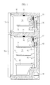
- FIG. 1 is a longitudinal-sectional view of a refrigerator in accordance with an embodiment of the present disclosure.
- the refrigerator in accordance with an embodiment of the present disclosure includes a freezing chamber 12 located above a diaphragm 11 forming a part of a main body 10 and provided with the opened front surface, a freezing chamber door 13 opening or closing the opened front surface of the freezing chamber 12, a refrigerating chamber 14 located under the diaphragm 11 and provided with the opened front surface, a refrigerating chamber door 15 opening or closing the opened front surface of the refrigerating chamber 14, and a compressor 16 provided at a rear portion of the lower portion of the main body 10.
- a freezing chamber heat exchange device 30 and 31 and a refrigerating chamber heat exchange device 40 and 41 performing heat exchange are provided between the rear surface portions of the freezing chamber 12 and the refrigerating chamber 14 and the main body 10, respectively.
- a freezing chamber temperature sensor 17 and a refrigerating chamber temperature sensor 18 are provided at designated portions of the walls of the freezing chamber 12 and the refrigerating chamber 14.
- Shelves 19 and baskets 20 to store food are provided within the freezing chamber 12 and the refrigerating chamber 14.
- a machinery chamber which is a separate space is provided at the rear portion of the lower portion of the main body 10, and the compressor 16 and the condenser 50 are provided within the machinery chamber.
- the freezing chamber heat exchange device 30 and 31 includes a freezing chamber evaporator 30 to cool air in the freezing chamber 12 through heat exchange, and a freezing chamber fan 31 installed above the freezing chamber evaporator 30 and circulating cool air having passed through the freezing chamber evaporator 30 to the inside of the freezing chamber 12.
- a suction hole 32 through which air in the freezing chamber 12 is sucked by driving of the freezing chamber fan 31 is formed below the freezing chamber evaporator 30, and a plurality of discharge holes 33 to uniformly discharge cool air blown by the freezing chamber fan 31 to the inside of the freezing chamber 12 is formed on the rear surface of the freezing chamber 12.
- the refrigerating chamber heat exchange device 40 and 41 includes a refrigerating chamber evaporator 40 to cool air in the refrigerating chamber 14 through heat exchange, and a refrigerating chamber fan 41 installed above the refrigerating chamber evaporator 40 and circulating cool air having passed through the refrigerating chamber evaporator 40 to the inside of the refrigerating chamber 14.
- a suction channel 42 to suck air in the refrigerating chamber 14 by driving of the refrigerating chamber fan 41 is provided below the refrigerating chamber evaporator 40, and a plurality of discharge holes 43 to uniformly discharge cool air blown by the refrigerating chamber fan 41 to the inside of the refrigerating chamber 14 is formed on the rear surface of the refrigerating chamber 14.
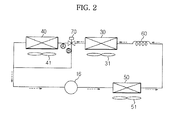
- FIG. 2 is a view illustrating a non-azeotropic refrigerant mixture (NARM) cycle of the refrigerator in accordance with an embodiment of the present disclosure.
- NARM non-azeotropic refrigerant mixture
- the refrigerator having the NARM cycle includes the compressor 16, a condenser 50, a capillary tube 60, the freezing chamber evaporator 30 and the refrigerating chamber evaporator 40, and these components are sequentially connected to refrigerant flow channels represented by solid lines.
- the capillary tube 60 is an example of an expansion device which decompresses and expands a refrigerant discharged from the condenser 50.
- a condenser fan 51 which sucks air at the outside of the refrigerator into the condenser 50 and then discharges the air to the outside of the refrigerator so as to rapidly perform heat exchange with air at the outside of the refrigerator is provided around the condenser 50.
- a freezing chamber fan 31 which sucks air at the inside of the freezing chamber 12 into the freezing chamber evaporator 30 and then discharges the air to the inside of the freezing chamber 12 so as to rapidly perform heat exchange with air at the inside of the freezing chamber 12 is provided around the freezing chamber evaporator 30.
- a refrigerating chamber fan 41 which sucks air at the inside of the refrigerating chamber 14 into the refrigerating chamber evaporator 40 and then discharges the air to the inside of the refrigerating chamber 14 so as to rapidly perform heat exchange with air at the inside of the refrigerating chamber 14 is provided around the refrigerating chamber evaporator 40.
- a 3-way valve 70 i.e., a flow channel switch valve to selectively change the respective refrigerant flow channels, is provided at an intersection of a refrigerant pipe connecting the freezing chamber evaporator 30 and the refrigerating chamber evaporator 40 and a refrigerant pipe connecting the freezing chamber evaporator and the inlet side of the compressor 16.
- NARM cycle having the above-described configuration is performed by circulating a non-azeotropic refrigerant mixture (NARM) along the components shown by arrows represented by dotted lines.
- NARM non-azeotropic refrigerant mixture
- the temperature of the NARM is changed during a phase change process differently from pure refrigerants generally used in refrigerators. That is, the temperature of the NARM is raised as the NARM is evaporated.
- efficiency of a refrigerator cycle increases as a compression ratio between a high-pressure side and a low-pressure side is reduced, and such a compression ratio is restricted by the refrigerant evaporation temperature of a freezing chamber evaporator.
- the evaporation temperature needs to be lower than such a temperature and thus the temperature of the inside of the freezing chamber acts as a critical point in decreasing the compression ratio.
- the refrigerant temperature at a point where evaporation is started is lower than the mean evaporation temperature, and thus, by applying the NARM to operation of the freezing chamber, the mean evaporation temperature may be raised as compared to a pure refrigerant and a compression ratio may be reduced.
- the refrigerator using the NARM cycle is configured such that the refrigerant first passes through the freezing chamber evaporator 30 and then passes through the refrigerating chamber evaporator 40 differently from a general refrigerator.
- the freezing chamber evaporator 30 is located at a position further upstream than the refrigerating chamber evaporator 40.
- the refrigerant discharged from the compressor 16 reaches the 3-way valve 70 via the condenser 50, the capillary tube 60 and the freezing chamber evaporator 30.
- the refrigerant pipe at the 3-way valve 70 is branched so that the refrigerant having passed through the freezing chamber evaporator 30 is introduced into the inlet side of the compressor 16 via the refrigerating chamber evaporator 40 or is introduced directly into the compressor 16 bypassing the refrigerating chamber evaporator 40 according to switching of the 3-way valve 70.
- a refrigerant flow channel A of the 3-way valve 70 is opened and a refrigerant flow channel B is closed by turning the 3-way valve 70 on. Further, if it is desired to introduce the refrigerant having passed through the freezing chamber evaporator 30 into the compressor 16 bypassing the refrigerating chamber evaporator 40, the refrigerant flow channel A of the 3-way valve 70 is closed and the refrigerant flow channel B is opened by turning the 3-way valve 70 off.
- a refrigerant in a gas phase compressed into a high-temperature and high-pressure state by the compressor 16 of the refrigerator is introduced into the condenser 50.
- the condenser 50 converts the refrigerant from the gas phase to a liquid phase by emitting heat to the outside through heat exchange with air at the outside of the refrigerator introduced by the condenser fan 51.
- the refrigerant in the liquid phase having passed through the condenser 50 is decompressed via the capillary tube 60, and is then introduced sequentially into the freezing chamber evaporator 30 and the refrigerating chamber evaporator 40.
- the freezing chamber evaporator 30 converts the refrigerant from the liquid phase to the gas phase by absorbing heat at the inside of the freezing chamber through heat exchange with air at the inside of the refrigerator introduced by the freezing chamber fan 31. Cool air is generated by such phase conversion of the refrigerant, and the generated cool air is introduced into the freezing chamber by the freezing chamber fan 31 and lowers the temperature of the freezing chamber. Further, the refrigerating chamber evaporator 40 converts the refrigerant from the liquid phase to the gas phase by absorbing heat at the inside of the refrigerating chamber through heat exchange between with air at the inside of the refrigerator introduced by the refrigerating chamber fan 41.
- Cool air is generated by such phase conversion of the refrigerant, and the generated cool air is introduced into the refrigerating chamber by the refrigerating chamber fan 41 and lowers the temperature of the refrigerating chamber.
- the refrigerant having passed through the refrigerating chamber evaporator 40 is introduced into the inlet side of the compressor 16.
- a refrigerant in a gas phase compressed into a high-temperature and high-pressure state by the compressor 16 of the refrigerator is introduced into the condenser 50.
- the condenser 50 converts the refrigerant from the gas phase to a liquid phase by emitting heat to the outside through heat exchange with air at the outside of the refrigerator introduced by the condenser fan 51.
- the refrigerant in the liquid phase having passed through the condenser 50 is decompressed via the capillary tube 60, and is then introduced into the freezing chamber evaporator 30.
- the freezing chamber evaporator 30 converts the refrigerant from the liquid phase to the gas phase by absorbing heat at the inside of the freezing chamber through heat exchange with air at the inside of the refrigerator introduced by the freezing chamber fan 31. Cool air is generated by such phase conversion of the refrigerant, and the generated cool air is introduced into the freezing chamber by the freezing chamber fan 31 and lowers the temperature of the freezing chamber.
- the refrigerant having passed through the freezing chamber evaporator 30 is introduced into the inlet side of the compressor 16.
- the refrigerator having the above-described configuration includes an operation control device 100 which increases evaporation latent heat of the refrigerant usable in the refrigerating chamber evaporator 40 in the simultaneous freezing/refrigerating operation mode.
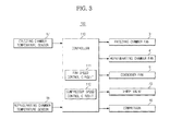
- FIG. 3 is a control block diagram of the refrigerator in accordance with an embodiment of the present disclosure
- FIG. 4 is a timing diagram illustrating rotational speed change of the freezing chamber fan in the freezing operation mode and the simultaneous freezing/refrigerating operation mode of the refrigerator in accordance with an embodiment of the present disclosure
- FIG. 5 is a timing diagram illustrating rotational speed change of the compressor in the freezing operation mode and the simultaneous freezing/refrigerating operation mode of the refrigerator in accordance with an embodiment of the present disclosure.
- the operation control device 100 includes a controller 110 which stores programs in the simultaneous freezing/refrigerating operation mode and the freezing operation mode and thus outputs control signals to the respective components to cool both the freezing chamber 12 and the refrigerating chamber 14 in the simultaneous freezing/refrigerating operation mode and to cool the freezing chamber 12 alone in the freezing operation mode.
- the controller 110 reduces evaporation latent heat of the refrigerant consumed by the freezing chamber evaporator 30 in the simultaneous freezing/refrigerating operation mode and thus relatively increases evaporation latent heat of the refrigerant consumed by the refrigerating chamber evaporator 40.
- the controller 110 changes the rotational speed of at least one of the freezing chamber fan 31 and/or the compressor 16 so as to increase evaporation latent heat of the refrigerant introduced into the refrigerating chamber evaporator 40.
- a method of reducing the rotational speed of the freezing chamber fan 31 in the simultaneous freezing/refrigerating operation mode or a method of stopping the freezing chamber fan 31 for a designated time in the simultaneous freezing/refrigerating operation mode may be used. These methods is to relatively increase evaporation latent heat usable in the refrigerating chamber evaporator 40 by relatively reducing evaporation latent heat consumed by the freezing chamber evaporator 30. Therethrough, cooling operation of the refrigerating chamber may be performed without increasing the amount of the refrigerant.
- a control method of the rotational speed of an inverter compressor may be used.
- the rotational speed of the compressor in the simultaneous freezing/refrigerating operation is increased as compared to the freezing operation, thereby exhibiting similar effects to the control method of the freezing chamber fan 31.
- the rotational speed of the compressor 16 in the simultaneous freezing/refrigerating operation is increased, the mass flow rate of the refrigerant circulating in the cycle is increased at the same refrigerant charging amount and thus evaporation latent heat of the refrigerant of a relatively larger amount may be used in the refrigerating chamber evaporator 40.
- the freezing chamber temperature sensor 17 to sense the temperature of the freezing chamber 12 and the refrigerating chamber temperature sensor 18 to sense the temperature of the refrigerating chamber 14 are electrically connected to the input side of the controller 110.
- the compressor 16, the freezing chamber fan 31, the refrigerating chamber fan 41 and the condenser fan 51 operated by control signals from the controller 110 are electrically connected to the output side of the controller 110.
- the controller 110 includes a fan speed control circuit 111 increasing and decreasing the rotational speed of the freezing chamber fan 31 and a compressor speed control circuit 112 increasing and decreasing the rotational speed of the compressor 16.
- the 3-way valve 70 operated by a control signal from the controller 110 is electrically connected to the output side of the controller 110.
- the above-described controller 110 performs one of the freezing operation mode and the simultaneous freezing/refrigerating operation mode.
- the controller 110 opens or closes the respective refrigerant flow channels A and B through the 3-way valve 70 in the freezing operation mode or the simultaneous freezing/refrigerating operation mode, thereby forming a freezing cycle or a freezing/refrigerating cycle.
- the controller 110 rotates the freezing chamber fan 31 at a reference speed N1 in the freezing operation mode, and decreases the rotational speed of the freezing chamber fan 31 to a speed N2 which is lower than the reference speed N1 in the simultaneous freezing/refrigerating operation mode.
- evaporation latent heat of the refrigerant consumed by the freezing chamber evaporator 30 in the simultaneous freezing/refrigerating mode may be reduced, and thus evaporation latent heat of the refrigerant usable in the refrigerant chamber evaporator 40 may be relatively increased.
- the controller 110 operates the freezing chamber fan 31 for a reference operation time in the freezing operation mode, and operates the freezing chamber fan 31 for a time shorter than the reference operation time in the freezing/refrigerating operation time. That is, the controller 110 forms a temporary stoppage section where the freezing chamber fan 31 is temporarily stopped in the simultaneous freezing/refrigerating operation mode.
- the controller 110 rotates the compressor 16 at a reference speed N1 in the freezing operation mode, and increases the rotational speed of the compressor 16 to a speed N2 which is higher than the reference speed N1 in the simultaneous freezing/refrigerating operation mode.
- evaporation latent heat of the refrigerant usable in the refrigerant chamber evaporator 40 in the simultaneous freezing/refrigerating mode may be relatively increased.
- FIG. 6 is a flowchart illustrating a control method of a refrigerator in accordance with an embodiment of the present disclosure.
- the controller 110 first senses the temperature of the freezing chamber 12, and determines whether or not a freezing operation condition is satisfied by comparing the sensed temperature with a predetermined temperature (Operation 200).
- the controller 110 turns the compressor 16 on (Operation 202). At this time, the controller 110 changes the refrigerant flow channel through the 3-way valve 70 so that the refrigerant having passed through the freezing chamber evaporator 30 is introduced into the inlet side of the compressor 16.
- the controller 110 rotates the freezing chamber fan 31 at a predetermined speed, i.e., a reference speed FS_r (Operation 204).
- the controller 110 determines whether or not a freezing operation off condition is satisfied (Operation 206).
- the controller 110 turns the compressor 16 off (Operation 208) and turns the freezing chamber fan 31 off (Operation 210).
- the controller 110 determines whether or not a simultaneous freezing/refrigerating operation condition is satisfied (Operation 212).
- the controller 110 turns the compressor 16 on (Operation 214). At this time, the controller 110 changes the refrigerant flow channel through the 3-way valve 70 so that the refrigerant having passed through the freezing chamber evaporator 30 is introduced into the inlet side of the compressor 16 via the refrigerating chamber evaporator 40.
- the controller 110 rotates the freezing chamber fan 31 at a speed FS (FS ⁇ FS_r) which is lower than the predetermined reference speed FS_r (Operation 216). At this time, the controller 110 operates the refrigerating chamber fan 41 at a reference speed RS.
- FIG. 7 is a flowchart illustrating a control method of a refrigerator in accordance with another embodiment of the present disclosure.
- the controller 110 first senses the temperature of the freezing chamber 12, and determines whether or not a freezing operation condition is satisfied by comparing the sensed temperature with a predetermined temperature (Operation 300).
- the controller 110 rotates the compressor 16 at a predetermined speed, i.e., a reference speed CS_r (Operation 302). At this time, the controller 110 changes the refrigerant flow channel through the 3-way valve 70 so that the refrigerant having passed through the freezing chamber evaporator 30 is introduced into the inlet side of the compressor 16.
- the controller 110 rotates the freezing chamber fan 31 at a predetermined speed, i.e., a reference speed FS_r (Operation 304).
- the controller 110 determines whether or not a freezing operation off condition is satisfied (Operation 306).
- the controller 110 turns the compressor 16 off (Operation 308) and turns the freezing chamber fan 31 off (Operation 310).
- the controller 110 determines whether or not a simultaneous freezing/refrigerating operation condition is satisfied (Operation 312).
- the controller 110 rotates the compressor 16 at a speed CS (CS>CS_r) which is higher than the predetermined reference speed CS_r (Operation 314). At this time, the controller 110 changes the refrigerant flow channel through the 3-way valve 70 so that the refrigerant having passed through the freezing chamber evaporator 30 is introduced into the inlet side of the compressor 16 via the refrigerating chamber evaporator 40.
- the controller 110 After rotation of the compressor 16 at the speed CS, the controller 110 rotates the freezing chamber fan 31 at the predetermined reference speed FS_r or a speed FS (FS ⁇ FS_r) which is lower than the predetermined reference speed FS_r (Operation 316). At this time, the controller 110 operates the refrigerating chamber fan 41 at a reference speed RS.
- sub-coolers In order to maximize effects of the NARM, the dryness and temperature of the refrigerant at the inlet of the evaporator need to be lowered, and for this purpose, sub-coolers may be mounted.
- the sub-coolers lower the dryness of the refrigerant at the inlet of the freezing chamber evaporator 30 (the outlet of the capillary tube) through heat exchange between the refrigerant pipe at the outlet of the condenser 50 and the refrigerant pipe at the outlet of the refrigerating chamber evaporator 40, and may thus lower the temperature of the refrigerant at the inlet of the freezing chamber evaporator 30.
- the number and positions of the sub-coolers may be varied according to characteristics of the cycle, and for example, two sub-coolers may be used.
- a sub-cooler performing heat exchange between the low-pressure side refrigerant pipe between the freezing chamber evaporator 30 and the refrigerating chamber evaporator 40 and the refrigerant pipe of the condenser 50 is referred to as a low temperature heat exchanger (LTHX), and serves both to lower the temperature of the refrigerant at the inlet of the freezing chamber evaporator and to raise a refrigerating chamber evaporation temperature. Since operation of the refrigerating chamber 14 uses a part of evaporation latent heat of the refrigerant, the dryness of which is high, and the refrigerating chamber evaporation temperature of the NARM becomes higher than that of a pure refrigerant.
- LTHX low temperature heat exchanger
- the LTHX may maximize reduction in the irreversible loss.
- HTHX high temperature heat exchanger
- a refrigerator in accordance with an embodiment of the present disclosure reduces the rotational speed of a freezing chamber fan or stopping the freezing chamber fan for a designated time, and/or increasing the rotational speed of a compressor in a simultaneous freezing/refrigerating operation mode of an NARM cycle as compared to a freezing operation mode, and may thus decrease evaporation latent heat of a refrigerant consumed by a freezing chamber evaporator and relatively increase evaporation latent heat of the refrigerant usable in a refrigerating chamber evaporator without increase in a charging amount of the refrigerant, thereby preventing over-charging due to increase in the charging amount of the refrigerant and reducing cycling loss.
Landscapes
- Engineering & Computer Science (AREA)
- Chemical & Material Sciences (AREA)
- Combustion & Propulsion (AREA)
- Physics & Mathematics (AREA)
- Mechanical Engineering (AREA)
- Thermal Sciences (AREA)
- General Engineering & Computer Science (AREA)
- Devices That Are Associated With Refrigeration Equipment (AREA)
Applications Claiming Priority (1)
| Application Number | Priority Date | Filing Date | Title |
|---|---|---|---|
| KR1020110115911A KR20130050700A (ko) | 2011-11-08 | 2011-11-08 | 비공비 혼합냉매를 이용한 냉장고 및 그 제어방법 |
Publications (2)
| Publication Number | Publication Date |
|---|---|
| EP2592372A2 true EP2592372A2 (de) | 2013-05-15 |
| EP2592372A3 EP2592372A3 (de) | 2015-09-09 |
Family
ID=47323895
Family Applications (1)
| Application Number | Title | Priority Date | Filing Date |
|---|---|---|---|
| EP12191517.7A Withdrawn EP2592372A3 (de) | 2011-11-08 | 2012-11-07 | Kühlschrank unter Verwendung eines nichtazeotropen Kühlgemischs und Steuerungsverfahren davon |
Country Status (4)
| Country | Link |
|---|---|
| US (1) | US20130111933A1 (de) |
| EP (1) | EP2592372A3 (de) |
| KR (1) | KR20130050700A (de) |
| CN (1) | CN103090619A (de) |
Cited By (2)
| Publication number | Priority date | Publication date | Assignee | Title |
|---|---|---|---|---|
| EP3643997A4 (de) * | 2017-06-19 | 2021-04-07 | Hisense Ronshen Guangdong Refrigerator Co., Ltd. | Kühlerbelüftungsystem und luftgekühlter kühlschrank |
| US11371768B2 (en) | 2018-12-28 | 2022-06-28 | Lg Electronics Inc. | Refrigerator and method for controlling the same |
Families Citing this family (16)
| Publication number | Priority date | Publication date | Assignee | Title |
|---|---|---|---|---|
| JP6334146B2 (ja) * | 2013-11-27 | 2018-05-30 | 東芝ライフスタイル株式会社 | 冷蔵庫 |
| KR102171448B1 (ko) * | 2014-02-11 | 2020-10-29 | 엘지전자 주식회사 | 냉장고의 인버터 압축기 및 냉장고 인버터 압축기의 제어 방법 |
| KR102267881B1 (ko) * | 2014-12-01 | 2021-06-23 | 삼성전자주식회사 | 냉장고 |
| KR102151817B1 (ko) * | 2016-11-30 | 2020-09-04 | 엘지전자 주식회사 | 냉장고 및 그의 제어방법 |
| KR102177946B1 (ko) * | 2016-12-02 | 2020-11-12 | 엘지전자 주식회사 | 냉장고 및 그의 제어방법 |
| US10544979B2 (en) | 2016-12-19 | 2020-01-28 | Whirlpool Corporation | Appliance and method of controlling the appliance |
| CN106839640A (zh) * | 2017-01-18 | 2017-06-13 | 合肥美的电冰箱有限公司 | 双制冷系统冰箱的控制方法、控制装置及双制冷系统冰箱 |
| CN110325690A (zh) * | 2017-04-25 | 2019-10-11 | 惠而浦有限公司 | 配置成采集大气水的制冷设备 |
| KR102496303B1 (ko) * | 2017-06-12 | 2023-02-07 | 엘지전자 주식회사 | 냉장고 및 그의 제어방법 |
| CN110131951B (zh) * | 2018-02-08 | 2021-06-04 | 日立环球生活方案株式会社 | 冰箱 |
| KR102939292B1 (ko) * | 2019-08-21 | 2026-03-13 | 엘지전자 주식회사 | 비공비혼합냉매를 사용하는 냉장고 |
| KR102838162B1 (ko) * | 2019-08-21 | 2025-07-25 | 엘지전자 주식회사 | 비공비혼합냉매를 사용하는 냉동시스템의 제어방법 |
| KR102831961B1 (ko) * | 2019-10-01 | 2025-07-08 | 일렉트로룩스 어플라이언스 아크티에볼레그 | 냉동고 용량이 큰 냉장 기기 |
| KR20210053714A (ko) * | 2019-11-04 | 2021-05-12 | 엘지전자 주식회사 | 냉장고 및 그의 제어방법 |
| CN112665299B (zh) * | 2020-12-11 | 2022-07-01 | 珠海格力电器股份有限公司 | 冰箱的制冷控制方法、装置、控制器和冰箱 |
| CN115247918A (zh) * | 2022-06-29 | 2022-10-28 | 宁波方太厨具有限公司 | 一种冰箱的制冷剂充注量确定方法 |
Family Cites Families (12)
| Publication number | Priority date | Publication date | Assignee | Title |
|---|---|---|---|---|
| US4416119A (en) * | 1982-01-08 | 1983-11-22 | Whirlpool Corporation | Variable capacity binary refrigerant refrigeration apparatus |
| US5406805A (en) * | 1993-11-12 | 1995-04-18 | University Of Maryland | Tandem refrigeration system |
| KR0149916B1 (ko) * | 1994-11-11 | 1999-05-01 | 김광호 | 고효율 독립냉각 싸이클을 가지는 냉장고의 운전제어장치 |
| KR0149917B1 (ko) * | 1994-11-11 | 1999-05-01 | 김광호 | 고효율 독립냉각 싸이클을 가지는 냉장고의 운전제어장치 |
| US5715693A (en) * | 1996-07-19 | 1998-02-10 | Sunpower, Inc. | Refrigeration circuit having series evaporators and modulatable compressor |
| US6438978B1 (en) * | 1998-01-07 | 2002-08-27 | General Electric Company | Refrigeration system |
| JP2000258020A (ja) * | 1999-03-11 | 2000-09-22 | Sharp Corp | 冷凍冷蔵庫 |
| US7062936B2 (en) * | 2003-11-21 | 2006-06-20 | U-Line Corporation | Clear ice making refrigerator |
| US20080156007A1 (en) * | 2006-12-28 | 2008-07-03 | Whirlpool Corporation | Distributed refrigeration system for modular kitchens |
| CN201110676Y (zh) * | 2007-12-04 | 2008-09-03 | 广东机电职业技术学院 | 带回热器的冰箱制冷循环系统 |
| DE202008000757U1 (de) * | 2007-12-28 | 2009-04-30 | Liebherr-Hausgeräte Ochsenhausen GmbH | Kühl- und/oder Gefriergerät |
| US10254026B2 (en) * | 2011-04-21 | 2019-04-09 | Hamilton Sundstrand Corporation | Control algorithm for electronic expansion valve modulation |
-
2011
- 2011-11-08 KR KR1020110115911A patent/KR20130050700A/ko not_active Withdrawn
-
2012
- 2012-11-07 EP EP12191517.7A patent/EP2592372A3/de not_active Withdrawn
- 2012-11-08 CN CN201210443057XA patent/CN103090619A/zh active Pending
- 2012-11-08 US US13/672,076 patent/US20130111933A1/en not_active Abandoned
Non-Patent Citations (1)
| Title |
|---|
| None |
Cited By (4)
| Publication number | Priority date | Publication date | Assignee | Title |
|---|---|---|---|---|
| EP3643997A4 (de) * | 2017-06-19 | 2021-04-07 | Hisense Ronshen Guangdong Refrigerator Co., Ltd. | Kühlerbelüftungsystem und luftgekühlter kühlschrank |
| US11226148B2 (en) | 2017-06-19 | 2022-01-18 | Hisense Ronshen (Guangdong) Refrigerator Co., Ltd. | Refrigerator |
| US11371768B2 (en) | 2018-12-28 | 2022-06-28 | Lg Electronics Inc. | Refrigerator and method for controlling the same |
| EP3674631B1 (de) * | 2018-12-28 | 2024-04-24 | LG Electronics Inc. | Kühlschrank und verfahren zur steuerung davon |
Also Published As
| Publication number | Publication date |
|---|---|
| CN103090619A (zh) | 2013-05-08 |
| US20130111933A1 (en) | 2013-05-09 |
| KR20130050700A (ko) | 2013-05-16 |
| EP2592372A3 (de) | 2015-09-09 |
Similar Documents
| Publication | Publication Date | Title |
|---|---|---|
| EP2592372A2 (de) | Kühlschrank unter Verwendung eines nichtazeotropen Kühlgemischs und Steuerungsverfahren davon | |
| KR0160436B1 (ko) | 고효율 독립냉각 싸이클을 가지는 냉장고 및 그 제어방법 | |
| US20110174005A1 (en) | Refrigerating apparatus | |
| EP3712541B1 (de) | Wärmepumpensystem | |
| EP2339274A2 (de) | Kühlschrank und Verfahren zur Steuerung seines Betriebs | |
| US11371768B2 (en) | Refrigerator and method for controlling the same | |
| KR101620430B1 (ko) | 냉장고 및 그 제어방법 | |
| US9267720B2 (en) | Air conditioner and method of controlling the same | |
| KR100377495B1 (ko) | 냉장고 | |
| JP2012255631A (ja) | 冷凍装置 | |
| US20200263916A1 (en) | Refrigeration machine | |
| KR102593575B1 (ko) | 냉장고 및 그의 제어방법 | |
| US10473388B2 (en) | Refrigerator and method for controlling constant temperature thereof | |
| CN106766535A (zh) | 一种冰箱的控制方法 | |
| JP4303062B2 (ja) | 冷蔵庫 | |
| JP2000230767A (ja) | 冷蔵庫 | |
| US20060236707A1 (en) | Refrigerator controlling method | |
| US20140284024A1 (en) | Method for controlling refrigerator | |
| CN111059786A (zh) | 用于冰箱的并联制冷系统和冰箱 | |
| CN100572992C (zh) | 冰箱 | |
| KR102617277B1 (ko) | 냉장고 및 그의 제어방법 | |
| JP2000283626A (ja) | 冷蔵庫 | |
| KR100743753B1 (ko) | 냉장고 및 냉장고의 제어 방법 | |
| JP2002206840A (ja) | 冷蔵庫 | |
| JP2007309585A (ja) | 冷凍装置 |
Legal Events
| Date | Code | Title | Description |
|---|---|---|---|
| PUAI | Public reference made under article 153(3) epc to a published international application that has entered the european phase |
Free format text: ORIGINAL CODE: 0009012 |
|
| AK | Designated contracting states |
Kind code of ref document: A2 Designated state(s): AL AT BE BG CH CY CZ DE DK EE ES FI FR GB GR HR HU IE IS IT LI LT LU LV MC MK MT NL NO PL PT RO RS SE SI SK SM TR |
|
| AX | Request for extension of the european patent |
Extension state: BA ME |
|
| PUAL | Search report despatched |
Free format text: ORIGINAL CODE: 0009013 |
|
| AK | Designated contracting states |
Kind code of ref document: A3 Designated state(s): AL AT BE BG CH CY CZ DE DK EE ES FI FR GB GR HR HU IE IS IT LI LT LU LV MC MK MT NL NO PL PT RO RS SE SI SK SM TR |
|
| AX | Request for extension of the european patent |
Extension state: BA ME |
|
| RIC1 | Information provided on ipc code assigned before grant |
Ipc: F25D 17/06 20060101ALI20150731BHEP Ipc: F25D 29/00 20060101AFI20150731BHEP |
|
| STAA | Information on the status of an ep patent application or granted ep patent |
Free format text: STATUS: THE APPLICATION IS DEEMED TO BE WITHDRAWN |
|
| 18D | Application deemed to be withdrawn |
Effective date: 20160310 |