EP2592467A2 - Ecran incluant un rétroéclairage secondaire - Google Patents
Ecran incluant un rétroéclairage secondaire Download PDFInfo
- Publication number
- EP2592467A2 EP2592467A2 EP11803732.4A EP11803732A EP2592467A2 EP 2592467 A2 EP2592467 A2 EP 2592467A2 EP 11803732 A EP11803732 A EP 11803732A EP 2592467 A2 EP2592467 A2 EP 2592467A2
- Authority
- EP
- European Patent Office
- Prior art keywords
- light guide
- guide panel
- display unit
- display device
- light
- Prior art date
- Legal status (The legal status is an assumption and is not a legal conclusion. Google has not performed a legal analysis and makes no representation as to the accuracy of the status listed.)
- Withdrawn
Links
- 239000004983 Polymer Dispersed Liquid Crystal Substances 0.000 claims abstract description 22
- 229920001621 AMOLED Polymers 0.000 claims description 3
- 230000003287 optical effect Effects 0.000 description 13
- 239000004973 liquid crystal related substance Substances 0.000 description 12
- 230000006866 deterioration Effects 0.000 description 7
- 238000005286 illumination Methods 0.000 description 5
- 238000009792 diffusion process Methods 0.000 description 3
- 230000001747 exhibiting effect Effects 0.000 description 2
- 230000002093 peripheral effect Effects 0.000 description 2
- 230000001681 protective effect Effects 0.000 description 2
- -1 acryl Chemical group 0.000 description 1
- 230000000903 blocking effect Effects 0.000 description 1
- 230000000694 effects Effects 0.000 description 1
- 239000011521 glass Substances 0.000 description 1
- 230000001788 irregular Effects 0.000 description 1
- 239000007788 liquid Substances 0.000 description 1
- 229920000642 polymer Polymers 0.000 description 1
- 230000005855 radiation Effects 0.000 description 1
- 239000007787 solid Substances 0.000 description 1
- 239000000758 substrate Substances 0.000 description 1
- 230000000007 visual effect Effects 0.000 description 1
Images
Classifications
-
- G—PHYSICS
- G02—OPTICS
- G02F—OPTICAL DEVICES OR ARRANGEMENTS FOR THE CONTROL OF LIGHT BY MODIFICATION OF THE OPTICAL PROPERTIES OF THE MEDIA OF THE ELEMENTS INVOLVED THEREIN; NON-LINEAR OPTICS; FREQUENCY-CHANGING OF LIGHT; OPTICAL LOGIC ELEMENTS; OPTICAL ANALOGUE/DIGITAL CONVERTERS
- G02F1/00—Devices or arrangements for the control of the intensity, colour, phase, polarisation or direction of light arriving from an independent light source, e.g. switching, gating or modulating; Non-linear optics
- G02F1/01—Devices or arrangements for the control of the intensity, colour, phase, polarisation or direction of light arriving from an independent light source, e.g. switching, gating or modulating; Non-linear optics for the control of the intensity, phase, polarisation or colour
- G02F1/13—Devices or arrangements for the control of the intensity, colour, phase, polarisation or direction of light arriving from an independent light source, e.g. switching, gating or modulating; Non-linear optics for the control of the intensity, phase, polarisation or colour based on liquid crystals, e.g. single liquid crystal display cells
- G02F1/133—Constructional arrangements; Operation of liquid crystal cells; Circuit arrangements
- G02F1/1333—Constructional arrangements; Manufacturing methods
- G02F1/1335—Structural association of cells with optical devices, e.g. polarisers or reflectors
- G02F1/1336—Illuminating devices
- G02F1/133602—Direct backlight
-
- G—PHYSICS
- G02—OPTICS
- G02F—OPTICAL DEVICES OR ARRANGEMENTS FOR THE CONTROL OF LIGHT BY MODIFICATION OF THE OPTICAL PROPERTIES OF THE MEDIA OF THE ELEMENTS INVOLVED THEREIN; NON-LINEAR OPTICS; FREQUENCY-CHANGING OF LIGHT; OPTICAL LOGIC ELEMENTS; OPTICAL ANALOGUE/DIGITAL CONVERTERS
- G02F1/00—Devices or arrangements for the control of the intensity, colour, phase, polarisation or direction of light arriving from an independent light source, e.g. switching, gating or modulating; Non-linear optics
- G02F1/01—Devices or arrangements for the control of the intensity, colour, phase, polarisation or direction of light arriving from an independent light source, e.g. switching, gating or modulating; Non-linear optics for the control of the intensity, phase, polarisation or colour
- G02F1/13—Devices or arrangements for the control of the intensity, colour, phase, polarisation or direction of light arriving from an independent light source, e.g. switching, gating or modulating; Non-linear optics for the control of the intensity, phase, polarisation or colour based on liquid crystals, e.g. single liquid crystal display cells
- G02F1/133—Constructional arrangements; Operation of liquid crystal cells; Circuit arrangements
- G02F1/1333—Constructional arrangements; Manufacturing methods
- G02F1/1347—Arrangement of liquid crystal layers or cells in which the final condition of one light beam is achieved by the addition of the effects of two or more layers or cells
- G02F1/13476—Arrangement of liquid crystal layers or cells in which the final condition of one light beam is achieved by the addition of the effects of two or more layers or cells in which at least one liquid crystal cell or layer assumes a scattering state
-
- G—PHYSICS
- G02—OPTICS
- G02B—OPTICAL ELEMENTS, SYSTEMS OR APPARATUS
- G02B6/00—Light guides; Structural details of arrangements comprising light guides and other optical elements, e.g. couplings
- G02B6/0001—Light guides; Structural details of arrangements comprising light guides and other optical elements, e.g. couplings specially adapted for lighting devices or systems
- G02B6/0011—Light guides; Structural details of arrangements comprising light guides and other optical elements, e.g. couplings specially adapted for lighting devices or systems the light guides being planar or of plate-like form
- G02B6/0075—Arrangements of multiple light guides
- G02B6/0076—Stacked arrangements of multiple light guides of the same or different cross-sectional area
-
- G—PHYSICS
- G02—OPTICS
- G02F—OPTICAL DEVICES OR ARRANGEMENTS FOR THE CONTROL OF LIGHT BY MODIFICATION OF THE OPTICAL PROPERTIES OF THE MEDIA OF THE ELEMENTS INVOLVED THEREIN; NON-LINEAR OPTICS; FREQUENCY-CHANGING OF LIGHT; OPTICAL LOGIC ELEMENTS; OPTICAL ANALOGUE/DIGITAL CONVERTERS
- G02F1/00—Devices or arrangements for the control of the intensity, colour, phase, polarisation or direction of light arriving from an independent light source, e.g. switching, gating or modulating; Non-linear optics
- G02F1/01—Devices or arrangements for the control of the intensity, colour, phase, polarisation or direction of light arriving from an independent light source, e.g. switching, gating or modulating; Non-linear optics for the control of the intensity, phase, polarisation or colour
- G02F1/13—Devices or arrangements for the control of the intensity, colour, phase, polarisation or direction of light arriving from an independent light source, e.g. switching, gating or modulating; Non-linear optics for the control of the intensity, phase, polarisation or colour based on liquid crystals, e.g. single liquid crystal display cells
- G02F1/133—Constructional arrangements; Operation of liquid crystal cells; Circuit arrangements
- G02F1/1333—Constructional arrangements; Manufacturing methods
- G02F1/1334—Constructional arrangements; Manufacturing methods based on polymer dispersed liquid crystals, e.g. microencapsulated liquid crystals
-
- G—PHYSICS
- G02—OPTICS
- G02F—OPTICAL DEVICES OR ARRANGEMENTS FOR THE CONTROL OF LIGHT BY MODIFICATION OF THE OPTICAL PROPERTIES OF THE MEDIA OF THE ELEMENTS INVOLVED THEREIN; NON-LINEAR OPTICS; FREQUENCY-CHANGING OF LIGHT; OPTICAL LOGIC ELEMENTS; OPTICAL ANALOGUE/DIGITAL CONVERTERS
- G02F1/00—Devices or arrangements for the control of the intensity, colour, phase, polarisation or direction of light arriving from an independent light source, e.g. switching, gating or modulating; Non-linear optics
- G02F1/01—Devices or arrangements for the control of the intensity, colour, phase, polarisation or direction of light arriving from an independent light source, e.g. switching, gating or modulating; Non-linear optics for the control of the intensity, phase, polarisation or colour
- G02F1/13—Devices or arrangements for the control of the intensity, colour, phase, polarisation or direction of light arriving from an independent light source, e.g. switching, gating or modulating; Non-linear optics for the control of the intensity, phase, polarisation or colour based on liquid crystals, e.g. single liquid crystal display cells
- G02F1/133—Constructional arrangements; Operation of liquid crystal cells; Circuit arrangements
- G02F1/1333—Constructional arrangements; Manufacturing methods
- G02F1/1335—Structural association of cells with optical devices, e.g. polarisers or reflectors
- G02F1/1336—Illuminating devices
- G02F1/133615—Edge-illuminating devices, i.e. illuminating from the side
-
- G—PHYSICS
- G07—CHECKING-DEVICES
- G07F—COIN-FREED OR LIKE APPARATUS
- G07F17/00—Coin-freed apparatus for hiring articles; Coin-freed facilities or services
- G07F17/32—Coin-freed apparatus for hiring articles; Coin-freed facilities or services for games, toys, sports, or amusements
- G07F17/3202—Hardware aspects of a gaming system, e.g. components, construction, architecture thereof
- G07F17/3204—Player-machine interfaces
- G07F17/3211—Display means
Definitions
- the present invention relates to a display device including a sub-backlight unit and, more particularly, to a display device, which can prevent visual obstruction caused by light reflected forwards by an article or a reel of a main display screen when light emitted from a light source of a sub-backlight unit reaches the article or the reel of the main display screen.
- the liquid crystal display device is disposed in front of a reel and includes a backlight unit which is provided with a light guide panel and a light source disposed at the circumference of the light guide panel.
- the light guide panel is provided with a transparent window.
- the transparent window is provided at a rear side thereof with a rotary reel having a symbol mark along a circumference thereof.
- a rotary reel display unit at a rear side can be viewed from a front side through the transparent window of the light guide panel and an image related to a game is displayed through the liquid crystal device on the front side, thereby invoking user interest in the game.
- the transparent window of the light guide panel becomes relatively dark and is distinguished from other portions of the display area of the liquid crystal display device or an image displayed through the liquid crystal display device can be blocked at a portion of the transparent window of the light guide panel.
- a sub-backlight unit including a second light guide panel and a second light source at a portion of a rear side of the backlight unit corresponding to the transparent window of the light guide panel (Korean Patent Application No. 10-2009-0102450 ).
- the problem of distinguishing the transparent window from other parts or blocking of an image can be solved by boosting radiation of light at a portion of the light guide panel corresponding to the transparent window using the sub-backlight unit.
- the slot machine including a sub-backlight unit has a problem in that a reel at the rear side of the slot machine cannot be clearly recognized due to a pattern part of the second light guide panel disposed at a portion of the light guide panel corresponding to the transparent window. Further, as light emitted from the second light source disposed at the circumference of the second light guide panel is introduced into the light guide panel and reaches a surface of the reel disposed at the rear side thereof to be reflected forwards thereby, a symbol mark formed along the circumference of the reel cannot be clearly recognized due to the reflected light, causing deterioration in display quality.
- Such a problem can also occur not only when a mechanical display device such as a reel, or a liquid crystal display device electronically realizing a reel is disposed at the rear side of the front display device, but also when an article other than the reel is disposed at the rear side of the front display unit.
- the present invention has been made to solve such problems of a display device such as a slot machine in the related art, and it is an aspect of the present invention to provide a display device, which includes a novel sub-backlight unit and is configured to display an image combined by a front display unit and a rear display unit, wherein a separate rear backlight unit is disposed to allow the rear display unit to be visible and to allow an overall area of the front display unit to be illuminated, such that the front display unit can display an entire screen without interruption and express game results, guide messages, and other game related images without restriction, and the rear display unit can be prevented from suffering deterioration in visibility by a second light guide panel or deterioration in display quality caused by reflected light of a light source of the second light guide panel, thereby improving visibility and quality of the rear display unit.
- the present invention provides a display device including a sub-backlight unit, including: a front display unit 10 and a rear display unit 50 disposed at a rear side of the front display unit 10 to allow an image of the rear display unit 50 to be visible through a portion of the front display unit 10, wherein the front display unit 10 includes a display panel 20; a first light guide panel 36 disposed at a rear side of the display panel 20 and having a transparent window 16 through which the rear display unit 50 is visible; a first light source 38 disposed around the first light guide panel 36; a front backlight unit 30 having a reflective sheet 39 disposed at a rear surface of the first light guide panel 36 to reflect light and having an image hole 18 formed corresponding to the transparent window 16; and a sub-backlight unit 40 disposed at a location corresponding to the transparent window 16 on a rear side of the front backlight unit 30, and wherein the sub-backlight unit 40 includes: a second light guide panel 41 having an opening 42 corresponding to the transparent window 16; a second light
- An inner circumferential surface of the opening 42 of the second light guide panel 41 may be an inclined surface enlarged from a rear side toward a front side.
- a prism sheet 45 may be attached to the inner circumferential surface of the opening 42 of the second light guide panel 41.
- An inner circumferential surface of the opening 42 of the second light guide panel 41 may be polished to be opaque.
- a light shielding tape 48 may be attached along an outer circumference of the opening 42 of the second light guide panel 41.
- the rear display unit 50 may be a rotary reel display unit having a plurality of rows of variable images.
- the rear display unit 50 may be one of an LCD, a PDP, an OLED, and an AMOLED.
- the rear display unit 50 may be a picture or an article representing an image.
- the transparent window 16 of the first light guide panel 36 may be an opening formed corresponding to a location of the rear display unit 50.
- a patterned-area section on which a pattern is printed may be formed on an area of the first light guide panel 36 outside the transparent window 16, and a non-patterned area section on which a pattern is not printed may be formed on an area of the first light guide panel 36 corresponding to the transparent window 16.
- the front backlight unit 30 having the transparent window 16 through which the rear display unit 50 is visible is disposed in the front display unit 10 and the sub-backlight unit 30 is disposed in an area of the front backlight unit 30 corresponding to the transparent window 16.
- the sub-backlight unit 40 includes the second light guide panel 41 having the opening 42 corresponding to the transparent window 16, the second light source 43 disposed at a circumference of the light guide panel 41, and a polymer dispersed liquid crystal (PDLC) sheet 44 disposed close to a front side of the opening 42 of the second light guide panel 41.
- PDLC polymer dispersed liquid crystal
- a power source of the PDLC sheet 44 is set to be visible, with the front backlight unit 30 of the front display unit 10 turned on, and the rear display unit 50 is then turned on. Then, the second light source 43 of the sub-backlight unit 30 is set to be turned on or off according to selection. Further, when the rear display unit 50 is to be blocked and only an image by the front display unit 10 is to be viewed, the power source of the PDLC sheet 44 is set to be opaque and the second light source 43 of the sub-backlight unit 40 is turned on, with the front backlight unit 30 of the front display unit 10 turned on, and the rear display unit 50 is turned off.
- the second light source 43 of the sub-backlight unit 40 is guided through the light guide panel 41 to illuminate the PDLC sheet 44, whereby the PDLC SHEET 44 acts as a light diffusing or scattering sheet and brightly illuminates the transparent window 16.
- the PDLC SHEET 44 acts as a light diffusing or scattering sheet and brightly illuminates the transparent window 16.
- the inner circumferential surface of the opening 42 of the second light guide panel 41 is formed as an inclined surface enlarged from a rear side toward a front side such that light emitted from a circumferential surface of the opening 42 of the second light guide panel 41 is guided forward, the light is prevented from proceeding toward the rear display unit 50.
- light from the second light source 43 can be prevented from being reflected towards the rear display unit 50, thereby making it possible to prevent deterioration in visibility and display quality.
- the prism sheet 45 is attached to the inner circumference of the opening 42 of the second light guide panel 41, light emitted from the second light guide panel 41 is guided only toward the PDLC sheet 44 instead of being radiated over a wide area, thereby further improving intensity of illumination of the PDLC sheet 44 and preventing light emitted from the second light source 43 from proceeding toward the rear display unit 50 and undergoing unnecessary reflection.
- the inner peripheral surface of the opening 42 of the second light guide panel 41 is polished to be opaque such that light emitted from the second light source 43 can be uniformly dispersed, thereby preventing a clear reflected image of the second light source 43 from being formed on the rear display unit 50.
- the light shielding tape 48 is attached along the outer circumference of the opening 42 of the second light guide panel 41 to prevent light emitted from the second light source 43 from reaching the rear display unit 50 along the outer circumference of the opening 42 of the second light guide panel 41, thereby preventing unnecessary reflection of light.
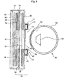
- Fig. 1 is a sectional view of a display device in accordance with one exemplary embodiment of the present invention
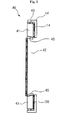
- Fig. 2 is a partially enlarged view of a main part of the display device in accordance with the exemplary embodiment of the present invention.
- the present invention relates to a display device which displays an image obtained by combining a front display unit and a rear display unit disposed at a rear side of the front display unit.
- a display device may be used in gaming devices such as slot machines, or may be used in various forms such as other types of gaming devices, 3D solid image display devices, and electronic picture frames.
- a liquid crystal display unit is used as a front display unit and a rotary reel display unit is used as a rear display unit.
- the rotary reel display unit may variably display symbol marks printed on a reel band to provide a game result according to combination of symbol marks.
- another type of display unit may be used as the rear display unit.
- a display unit such as an LCD, a PDP, an OLED and an AMOLED, or a picture or an article, for example jewelry, which represents an image, may be used as the rear display unit.
- a display panel 20, a front optical shutter 46, a front backlight unit 30, and a rear backlight unit 40 constitute a multilayered structure of a front display unit 10.
- a rear display unit 50 is disposed at a rear side of the front display unit 10.
- the display panel 20 may be a liquid crystal display panel, and has a structure wherein polarizing films are disposed on front and rear surfaces of the panel to which a TFT substrate and a color filter are bonded, respectively.
- the front optical shutter 46 is disposed at a rear side of the display panel 20.
- the front optical shutter 46 optically transmits or blocks light of the front backlight unit 30 according to selection.
- the front optical shutter 40 transmits light such that the rear display unit 50 is visible from a front side, and when a voltage is not applied, the front optical shutter 40 blocks light such that the rear display unit 50 is invisible, whereby screen uniformity can be improved or calibrated by diffusing light emitted from the front backlight unit 30 or the rear backlight unit 40.
- the front backlight unit 30 includes optical sheets such as a prism sheet 32 and a diffusion sheet 34, a first light guide panel 36, a first light source 38, and a reflective sheet 39.
- the prism sheet 32 is an optical sheet for condensing light
- the diffusion sheet 34 is an optical sheet for dispersing light to obtain uniformity of light.
- Such optical sheets may be selectively used or may be replaced by other optical sheets.
- the front backlight unit may include a protective sheet. A partially opened image hole 18 is formed in each of the optical sheets such that the rear display unit 50 is visible therethrough.
- the first light guide panel 36 receives light through a side surface thereof to emit light through a front surface thereof when the light is emitted from the first light source 38 disposed at a circumference thereof, and is made of transparent acryl.
- the first light source 38 may be a CCFL or an LED.
- the first light guide panel 36 is formed with the transparent window 16 through which the rear display unit 50 is visible.
- the transparent window 16 is a non-light emitting area and is not affected by light emitted from the front backlight unit 30. Thus, even when a screen is displayed on the display panel 20, the rear display unit 50 can be viewed through the transparent window 16.
- the transparent window 16 is formed by forming an opening at a central portion of the first light guide panel 36.
- a patterned-area section on which a predetermined pattern for refracting or scattering light, for example, a dot pattern, is printed or formed, is formed on an area of the first light guide panel 36 outside the transparent window 16, and a non-patterned area section on which such a pattern is not formed is formed on an area of the first light guide panel 36 corresponding to the transparent window 16 and functions as a transparent window.
- the reflective sheet 39 is disposed on a rear surface of the first light guide panel 36 to reflect light, and is formed with an image hole 18 corresponding to the transparent window 16 as in the aforementioned optical sheet.
- the reflective sheet 39 may be provided by attaching a reflective film to a front side of a protective glass sheet.
- the display panel 20 and the front backlight unit 30 of the front display unit 10 are received in a single main frame 12.
- the sub-backlight unit 40 is disposed at a portion of the front backlight unit 30 corresponding to the transparent window 16.
- the sub-backlight unit 40 includes a second light guide panel 41 disposed within a sub-frame 14 and having an opening 42 at a portion corresponding to the transparent window 16, a second light source 43 disposed at a circumference of the second light guide panel 41, and a polymer dispersed liquid crystal (PDLC) sheet 44 disposed close to a front side of the opening 42 of the second light guide panel 41.
- PDLC polymer dispersed liquid crystal
- An inner circumferential surface of the opening 42 is an inclined surface which is gradually enlarged from the rear side toward the front side, that is, from a side of the rear display unit 50 toward the front backlight unit 30 to guide light of the sub-backlight unit 40 toward the PDLC sheet 44. Further, a prism sheet 45 is attached to the inner circumferential surface of the opening 42 to allow light emitted from the inner circumferential surface of the opening 42 to travel straight in order to prevent the light from being unnecessarily diffused and reflected by the rear display unit 50, thereby preventing deterioration in visibility or display quality.
- the PDLC sheet 44 contains liquid crystals dispersed in a polymer and is formed without using a polarizing film.
- the PDLC sheet 44 blocks light while functioning as a diffusion sheet through an irregular arrangement of liquid crystal molecules when voltage is not applied thereto, and is switched to a light transmitting state through regular arrangement of the liquid crystal molecules upon application of voltage thereto.
- the PDLC sheet 44 functions as an optical shutter such that the rear display unit 50 is visible when light can be transmitted therethrough, and the PDLC sheet functions as a light diffusing or scattering sheet of the sub-backlight unit 40, so that the transparent window 16 may be prevented from being distinguished from an area except for the transparent window 16 or exhibiting low intensity of illumination by increasing the intensity of illumination at the transparent window 16.
- the PDLC sheet 44 when used as the light diffusing sheet for the transparent window 16, it is possible to prevent a problem caused by a light guide panel disposed on the transparent window 16 to increase the intensity of illumination, that is, deterioration in visibility of the rear display unit 50 due to the pattern of the light guide panel.
- the inner circumferential surface of the opening 42 may be polished to be opaque instead of or together with the prism sheet 45.
- a clear reflected image of the second light source 43 is prevented from being formed on the rear display unit 50.
- the light shielding tape 48 is attached along the outer circumference of the opening 42 of the second light guide panel 41 to prevent light emitted from the second light source 43 from reaching the rear display unit 50 along the outer circumference of the opening 42 of the second light guide panel 41, thereby preventing unnecessary reflection of light.
- a rotary reel display unit is provided as the rear display unit 50 of the present embodiment.
- a reel band 54 is attached to an outer peripheral surface of the rotary reel 52 and symbol marks (not shown) are attached to the reel band 54.
- a rear display lighting unit 56 for illuminating the symbol marks is disposed inside or outside the rotary reel 52.
- the rotary reel 52 is illuminated by the rear display illuminating unit 56 so that the rear display unit 50 is visible, and when the rotary reel 52 is rotated and then stopped, a game result is determined through combination of the symbol marks transmitted through the front display unit 10.
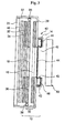
- Fig. 3 shows another embodiment of the present invention, in which the rear display unit 50 is formed by a liquid display unit instead of the rotary reel display unit.
- the rear display unit 50 may be constituted by a liquid crystal display or other flat panel display devices so that symbol marks of a slot machine can be displayed through an image instead of a mechanical reel.
- the rear display unit 50 may be realized by a picture or an article.
Landscapes
- Physics & Mathematics (AREA)
- Nonlinear Science (AREA)
- General Physics & Mathematics (AREA)
- Optics & Photonics (AREA)
- Mathematical Physics (AREA)
- Chemical & Material Sciences (AREA)
- Crystallography & Structural Chemistry (AREA)
- Liquid Crystal (AREA)
- Devices For Indicating Variable Information By Combining Individual Elements (AREA)
- Slot Machines And Peripheral Devices (AREA)
- Planar Illumination Modules (AREA)
Applications Claiming Priority (2)
| Application Number | Priority Date | Filing Date | Title |
|---|---|---|---|
| KR1020100065052A KR101153892B1 (ko) | 2010-07-06 | 2010-07-06 | 서브백라이트를 구비한 디스플레이장치 |
| PCT/KR2011/004017 WO2012005446A2 (fr) | 2010-07-06 | 2011-06-01 | Ecran incluant un rétroéclairage secondaire |
Publications (2)
| Publication Number | Publication Date |
|---|---|
| EP2592467A2 true EP2592467A2 (fr) | 2013-05-15 |
| EP2592467A4 EP2592467A4 (fr) | 2015-11-25 |
Family
ID=45441612
Family Applications (1)
| Application Number | Title | Priority Date | Filing Date |
|---|---|---|---|
| EP11803732.4A Withdrawn EP2592467A4 (fr) | 2010-07-06 | 2011-06-01 | Ecran incluant un rétroéclairage secondaire |
Country Status (4)
| Country | Link |
|---|---|
| US (1) | US8830421B2 (fr) |
| EP (1) | EP2592467A4 (fr) |
| KR (1) | KR101153892B1 (fr) |
| WO (1) | WO2012005446A2 (fr) |
Families Citing this family (8)
| Publication number | Priority date | Publication date | Assignee | Title |
|---|---|---|---|---|
| JP6515652B2 (ja) * | 2015-04-15 | 2019-05-22 | オムロン株式会社 | 表示装置及び遊技機 |
| CN104791670A (zh) * | 2015-05-05 | 2015-07-22 | 武汉华星光电技术有限公司 | 背光模块及液晶显示器 |
| JP2017107048A (ja) * | 2015-12-09 | 2017-06-15 | オムロン株式会社 | 表示装置及び遊技機 |
| KR102882860B1 (ko) * | 2020-01-16 | 2025-11-10 | 삼성디스플레이 주식회사 | 표시 장치 |
| JP7439532B2 (ja) * | 2020-01-24 | 2024-02-28 | オムロン株式会社 | 電飾装置および遊技機 |
| JP7439531B2 (ja) | 2020-01-24 | 2024-02-28 | オムロン株式会社 | 電飾装置および遊技機 |
| CN113628530B (zh) * | 2020-05-07 | 2023-09-26 | 群创光电股份有限公司 | 显示装置以及移动装置 |
| KR102362710B1 (ko) | 2020-05-22 | 2022-02-14 | 주식회사 토비스 | 투과부를 갖는 도광판 및 디스플레이 모듈과, 이를 구비한 게임기 |
Family Cites Families (11)
| Publication number | Priority date | Publication date | Assignee | Title |
|---|---|---|---|---|
| JP2004166964A (ja) * | 2002-11-20 | 2004-06-17 | Aruze Corp | 遊技機 |
| JP2004166961A (ja) * | 2002-11-20 | 2004-06-17 | Aruze Corp | 遊技機 |
| US7307675B2 (en) * | 2004-12-07 | 2007-12-11 | Planar Systems, Inc. | Display panel with backlighting structure and selectively transmissive window therethrough |
| JP2007071897A (ja) * | 2005-09-02 | 2007-03-22 | Toshiba Matsushita Display Technology Co Ltd | 液晶表示装置 |
| JP4954545B2 (ja) * | 2005-11-18 | 2012-06-20 | 高砂電器産業株式会社 | 遊技機用表示装置 |
| JP2007268173A (ja) | 2006-03-31 | 2007-10-18 | Sharp Corp | 表示装置及びその製造方法、並びに、遊技機 |
| KR100858868B1 (ko) * | 2006-11-07 | 2008-09-17 | 주식회사 토비스 | 슬롯머신용 릴게임에서의 절환게임이 가능한 화상디스플레이 패널 투광구조 |
| KR100989902B1 (ko) | 2008-03-26 | 2010-10-26 | 조현춘 | 반도체 패키지와 이의 제조방법 |
| KR100956618B1 (ko) | 2008-06-09 | 2010-05-11 | 주식회사 토비스 | 백라이트 유닛, 그리고 이를 포함하는 액정 표시 장치와게임기 |
| KR100961903B1 (ko) * | 2008-06-09 | 2010-06-10 | 주식회사 토비스 | 백라이트 유닛, 그리고 이를 포함하는 액정 표시 장치와게임기 |
| KR101046224B1 (ko) | 2009-10-27 | 2011-07-04 | (주)코텍 | 디스플레이장치 |
-
2010
- 2010-07-06 KR KR1020100065052A patent/KR101153892B1/ko not_active Expired - Fee Related
-
2011
- 2011-06-01 WO PCT/KR2011/004017 patent/WO2012005446A2/fr not_active Ceased
- 2011-06-01 EP EP11803732.4A patent/EP2592467A4/fr not_active Withdrawn
- 2011-06-01 US US13/735,084 patent/US8830421B2/en not_active Expired - Fee Related
Also Published As
| Publication number | Publication date |
|---|---|
| KR20120004278A (ko) | 2012-01-12 |
| WO2012005446A3 (fr) | 2012-03-01 |
| EP2592467A4 (fr) | 2015-11-25 |
| US8830421B2 (en) | 2014-09-09 |
| KR101153892B1 (ko) | 2012-06-05 |
| WO2012005446A2 (fr) | 2012-01-12 |
| US20130135560A1 (en) | 2013-05-30 |
Similar Documents
| Publication | Publication Date | Title |
|---|---|---|
| US8830421B2 (en) | Display device including sub-backlight | |
| KR101046224B1 (ko) | 디스플레이장치 | |
| US9101826B2 (en) | Display device for a slot machine | |
| US8287370B2 (en) | Liquid crystal display unit, game device and display method for use in liquid crystal display unit | |
| KR101068154B1 (ko) | 디스플레이장치 | |
| US9329425B2 (en) | Transparent display apparatus | |
| US20100144432A1 (en) | Liquid crystal display unit . gaming device ,and display method of liquid crystal display unit | |
| JP2011107229A (ja) | 液晶モジュールおよび電子機器 | |
| US8836891B2 (en) | Liquid crystal display device and game device | |
| JP5160635B2 (ja) | 液晶表示ユニット、液晶表示ユニットの制御方法及び遊技装置 | |
| KR101165437B1 (ko) | 디스플레이장치 | |
| WO2010095303A1 (fr) | Dispositif d'affichage à cristaux liquides et dispositif de jeu | |
| KR100984804B1 (ko) | 이중 표시기능을 갖는 백라이트 유닛 | |
| JP3324512B2 (ja) | 液晶表示装置 | |
| WO2013161945A1 (fr) | Appareil de source de lumière et dispositif électronique | |
| KR20190043986A (ko) | 디스플레이 장치 | |
| JP2006181372A (ja) | 照明装置付きの遊技機 | |
| KR200354621Y1 (ko) | 내부화면창을 구비한 액정표시장치 | |
| KR100587469B1 (ko) | 내부화면창을 구비한 액정표시장치 | |
| JP2004013174A (ja) | 照光ユニット | |
| JP2005208372A (ja) | 液晶表示装置およびこれを用いた遊技機 | |
| JP2006098550A (ja) | 液晶表示装置 | |
| HK1078655B (en) | Backlighting device for an information display element of a portable object | |
| HK1078655A1 (zh) | 用於便携式物体的信息显示元件的背光装置 | |
| JP2006047930A (ja) | 液晶表示装置 |
Legal Events
| Date | Code | Title | Description |
|---|---|---|---|
| PUAI | Public reference made under article 153(3) epc to a published international application that has entered the european phase |
Free format text: ORIGINAL CODE: 0009012 |
|
| 17P | Request for examination filed |
Effective date: 20130204 |
|
| AK | Designated contracting states |
Kind code of ref document: A2 Designated state(s): AL AT BE BG CH CY CZ DE DK EE ES FI FR GB GR HR HU IE IS IT LI LT LU LV MC MK MT NL NO PL PT RO RS SE SI SK SM TR |
|
| DAX | Request for extension of the european patent (deleted) | ||
| A4 | Supplementary search report drawn up and despatched |
Effective date: 20151027 |
|
| RIC1 | Information provided on ipc code assigned before grant |
Ipc: G02F 1/1347 20060101AFI20151021BHEP Ipc: G02F 1/1335 20060101ALN20151021BHEP Ipc: F21V 8/00 20060101ALI20151021BHEP Ipc: G02F 1/1334 20060101ALN20151021BHEP Ipc: G07F 17/32 20060101ALI20151021BHEP |
|
| GRAP | Despatch of communication of intention to grant a patent |
Free format text: ORIGINAL CODE: EPIDOSNIGR1 |
|
| RIC1 | Information provided on ipc code assigned before grant |
Ipc: G07F 17/32 20060101ALI20160623BHEP Ipc: G02F 1/1335 20060101ALN20160623BHEP Ipc: G02F 1/1347 20060101AFI20160623BHEP Ipc: G02F 1/1334 20060101ALN20160623BHEP Ipc: F21V 8/00 20060101ALI20160623BHEP |
|
| INTG | Intention to grant announced |
Effective date: 20160714 |
|
| STAA | Information on the status of an ep patent application or granted ep patent |
Free format text: STATUS: THE APPLICATION IS DEEMED TO BE WITHDRAWN |
|
| 18D | Application deemed to be withdrawn |
Effective date: 20161125 |