EP2592707A1 - Procédé d'adaptation d'un réseau de communication et réseau de communication - Google Patents
Procédé d'adaptation d'un réseau de communication et réseau de communication Download PDFInfo
- Publication number
- EP2592707A1 EP2592707A1 EP12192036.7A EP12192036A EP2592707A1 EP 2592707 A1 EP2592707 A1 EP 2592707A1 EP 12192036 A EP12192036 A EP 12192036A EP 2592707 A1 EP2592707 A1 EP 2592707A1
- Authority
- EP
- European Patent Office
- Prior art keywords
- tube
- signal
- signal conductor
- conductor
- network
- Prior art date
- Legal status (The legal status is an assumption and is not a legal conclusion. Google has not performed a legal analysis and makes no representation as to the accuracy of the status listed.)
- Granted
Links
Images



Classifications
-
- H—ELECTRICITY
- H02—GENERATION; CONVERSION OR DISTRIBUTION OF ELECTRIC POWER
- H02G—INSTALLATION OF ELECTRIC CABLES OR LINES, OR OF COMBINED OPTICAL AND ELECTRIC CABLES OR LINES
- H02G1/00—Methods or apparatus specially adapted for installing, maintaining, repairing or dismantling electric cables or lines
- H02G1/06—Methods or apparatus specially adapted for installing, maintaining, repairing or dismantling electric cables or lines for laying cables, e.g. laying apparatus on vehicle
- H02G1/08—Methods or apparatus specially adapted for installing, maintaining, repairing or dismantling electric cables or lines for laying cables, e.g. laying apparatus on vehicle through tubing or conduit, e.g. rod or draw wire for pushing or pulling
-
- G—PHYSICS
- G02—OPTICS
- G02B—OPTICAL ELEMENTS, SYSTEMS OR APPARATUS
- G02B6/00—Light guides; Structural details of arrangements comprising light guides and other optical elements, e.g. couplings
- G02B6/44—Mechanical structures for providing tensile strength and external protection for fibres, e.g. optical transmission cables
- G02B6/4439—Auxiliary devices
- G02B6/4459—Ducts; Conduits; Hollow tubes for air blown fibres
Definitions
- This invention relates to a method for adapting a communication network.
- the invention relates to a communication network as such.
- a known net is provided with outer tubes, normally extending in the ground, each provided with inner tubes, which in themselves are provided with various cables having a signal conducting (copper) core.
- This network is also known by the name of 'Flashnet'.
- the Flashnet is used in particular for communication connections to end users (e.g., local communication means in buildings, houses, and the like, associated with end users).
- end users e.g., local communication means in buildings, houses, and the like, associated with end users.
- a number (e.g., one) of the inner tubes may be still empty, at least, not provided with a cable having a signal conducting core.
- JP2002247724 describes a method for installing a communication cable, for instance in a sewer, wherein guide pipe is divided into different compartments to receive telecommunication cables (16), telephone lines (17), a main cable (28), and thin wires (22).
- JP200417439 discloses a method in which an inflatable tube is passed to an end user via a subterranean pipe, to feed through a new cable.
- a method for adapting a communication network the network being at least provided with:
- new signal conductors can be installed, with utilization of an empty second tube (e.g., an empty inner tube which extends through an outer tube), at a time when respective end users are still in communication connection with the network (i.e., in that those end users are still connected to old signal conductors which extend through the first tubes of the tube bundle).
- an empty second tube e.g., an empty inner tube which extends through an outer tube
- the new signal conductors are installed, as desired, one or more of the end users can be rapidly switched from communication via the old signal conductor(s) to communication via the new communication conductor(s).
- the bundle of tubes can comprise, for instance, a number of inner tubes extending through a bundle holder.
- a bundle holder can for instance be an outer tube, or comprise one or more sleeves (e.g., a single elongate sleeve or a series of sleeves), and/or comprise one or more binders, tape, a skin, and/or a combination of these or other bundle holders.
- the first tubes and second tube are a bundle of mutually loose (i.e., not directly connected to each other) tubes.
- An above-mentioned old signal conductor i.e., a first signal conductor
- An above-mentioned new signal conductor i.e., a second signal conductor in replacement of communication via a first signal conductor
- the second signal conductor is installed during a network operating period, in which period the respective network end user is in communication connection with the network via the respective first signal conductor.
- the bundle holder can be opened at a branch to the respective end user to access the respective second signal conductor, and to feed it through to the end user.
- Each second signal conductor may during installation be passed, for instance, through the whole second tube, for instance in a loose bundle of second signal conductors.
- the signal conductor can be passed along a path that extends along several end users (and several branches to respective end users, i.e., end user locations).
- the path mentioned can be determined, for instance, by the tube bundle already installed.
- one of the second signal conductors can be made available, and be passed via the branch to the end user.
- the making available of the second signal conductor comprises, for instance, the making available of a branch portion of that signal conductor, which signal conductor branch portion is passed (via the branch) to the end user.
- the signal conductor branch portion can for instance (locally, at the respective branch) be pulled out of the second tube, whether or not after separation from a remaining part of the respective second signal conductor (which remaining part, for instance, remains behind in the second tube).
- the thus branched-off portion of the second signal conductor can for instance be connected at the end user to suitable communication means (e.g., optical communication means, in the case where the second signal conductor is configured for communication with utilization of optical communication signals).
- the end user may for instance be connected to a second signal conductor by installing a separate signal conductor, which is brought into communication connection with the second signal conductor available locally (at a respective branch to that end user).
- Bringing second signal conductors, for instance optical fibers, into communication connection is technology generally known per se, and comprises for instance fusion welding (splicing).
- an above-mentioned branch can comprise, for instance, a branch outer tube, having extending therethrough a first branch signal conductor (e.g., a cable having a copper core) which is associated with a first signal conductor (e.g., a cable having a copper core).
- the first branch signal conductor can extend, for instance, in a branch inner tube, which has been passed through the branch outer tube.
- the end user may for instance be connected to that particular first branch signal conductor.
- a second branch inner tube can then be passed through the branch outer tube, in which case for instance a branch portion of a second signal conductor is passed through the second branch inner tube for connection to the respective end user. Thereupon the end user can be rapidly, locally, transferred (to communication via the second signal conductor).
- At least as many second signal conductors are arranged in the second tube as the number of first signal conductors extending through the respective first tubes (i.e., of the same bundle).
- the network can be rapidly provided with sufficient second signal conductors, to enable replacement of communication via respective first signal conductors at desired moments.
- the bundle of tubes may include different empty (i.e., not provided with a first signal conductor) second tubes, in addition to the first tubes provided with first signal conductors.
- second signal conductors can be arranged in the second tubes as the number of first signal conductors extending through the respective first tubes.
- (the) several second signal conductors may be arranged in a second tube simultaneously, for instance in a bundle, which enhances efficiency and increases installation speed.
- each second signal conductor is passed through the second inner tube under the influence of a fluid flow.
- Each second signal conductor can for instance extend substantially throughout the length (e.g., at least throughout the length) of the second tube, after being passed through that tube.
- the second tube can also extend substantially throughout the length (e.g., at least throughout the length) of an optional bundle holder, for instance an above-mentioned outer tube or the like.
- first signal conductors can for instance remain behind in the network, in unused condition, for instance as back-up signal conductors.
- first signal conductors may for instance remain active, and, for instance, remain connected or be connected to communication means or other means of the respective end user, for transmitting signals (e.g., communication signals, television signals, telephone signals, audio and/or video signals, and/or other signals).
- signals e.g., communication signals, television signals, telephone signals, audio and/or video signals, and/or other signals.
- an end user may be connected via both a first and a second signal conductor to respective network means, for simultaneous signal transfer via the first and second signal conductor.
- the invention provides a communication network, for instance installed by means of a method according to the invention, the network being at least provided with:
- the bundle of first and second tubes can for instance include different (e.g., two) second tubes, in which case preferably at least as many second signal conductors are arranged in the second tubes as the number of first signal conductors extending through the respective first tubes.
- Figs. 1, 2 schematically show a part of a communication network, in particular a Flashnet.
- the network part is configured for communication between a number of network end users E (e.g., local communication means belonging to houses or the like) and network means M (comprising, e.g., one or more communication lines, one or more patch stations, one or more network intermediate stations and/or one or more network distribution stations, one or more network servers, and/or other network means).
- E e.g., local communication means belonging to houses or the like
- network means M comprising, e.g., one or more communication lines, one or more patch stations, one or more network intermediate stations and/or one or more network distribution stations, one or more network servers, and/or other network means).
- the network part shown comprises at least a bundle of tubes including first tubes 3 and a second tube 5, and - in this example - at least one bundle holder 1.
- the bundle holder 1 can be implemented in different manners, and, for instance, comprise an outer tube (as in a Flashnet), comprise one or more sleeves (e.g., a single elongate sleeve or a series of sleeves), one or more binders, tape, a skin, and/or a combination of these or other bundle holders.
- the bundle holder comprises at least one hollow outer tube 1.
- the outer tube 1 is provided with several first inner tubes 3 extending through an interior 1a of the outer tube 1 (see Fig. 2 ).
- first signal conductors 2 of a first conductor type, associated with network end users E, extend through the first (inner) tubes 3.
- Outer tube branches T are provided to pass the signal conductors 2 to respective end users E.
- An above-mentioned branch comprises, for instance, a branch outer tube 11 (see Figs. 1 , 5 , 6 ), with a branch signal conductor 12 extending therethrough, which is associated with a first signal conductor 2.
- a first signal conductor 2 may be brought into communicative connection with a respective branch signal conductor 12, for instance by means of a local coupling means 50.
- the branch signal conductor 12 may be passed through the branch outer tube 11 to the end user E via a respective inner tube 13.
- the represented part of the Flashnet is provided with an empty second (likewise hollow) inner tube 5 (i.e., a second tube 5) extending through the outer tube 1, along the branches T, which does not contain a first signal conductor.
- the first signal conductors 2 are, for instance, out-of-date signal conductors, which are due for replacement. They are, for instance, signal conducting cables having a copper signal conducting core 2a.
- At least one second signal conductor 4, of a second conductor type which is different from the first conductor type is passed through the second (inner) tube 5, wherein the second signal conductor 4 is associated with a network end user E which is already provided with a first signal conductor 2.
- This is schematically represented in Figs. 3-6 .
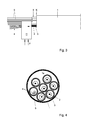
- Fig. 3 shows in particular the insertion into the second inner tube of a number of second signal conductors 4, for instance jointly, simultaneously, in a bundle of loose signal conductors 4.
- the second signal conductors 4, after insertion, are preferably substantially loosely arranged in the respective second inner tube 5 (at least, are not directly fixed to that second inner tube 5).
- each second signal conductor 4 is so installed in the second inner tube that all those conductors extend along several branches T of the outer tube 1. After being fed through, each second signal conductor 4 may extend, for instance, substantially throughout the length of the second inner tube 5, and preferably substantially throughout the length of the protective outer tube 1.
- the outer tube 1 is typically relatively long, having a length of, for instance, at least 100 meters, and in certain cases, for instance, about at least 400 meters or at least 1 km.
- a second signal conductor 4 can then likewise have a length of at least 100 meters, for instance, (at least) about 400 meters or at least about 1 km.
- different second signal conductors 4 may extend over different distances through the outer tube 1 and respective inner tubes 5.
- the length of a second signal conductor 4 is in any case preferably such that this signal conductor 4, from an outer tube insertion position K, can reach a predetermined end user E, or a branch T to such predetermined end user E, to enable, if required, installation of a communication connection with such predetermined end user E via that conductor 4.
- each second signal conductor 4 is passed through the second inner tube 5 under the influence of a fluid flow.
- Fig. 3 schematically shows utilization of a blowing device H which is configured to blow air F into a linked-up second inner tube 5, and thus (under the influence of flow resistance and pressure difference) to drag the second signal conductors 4 through the tube 5.
- a blowing device H which is configured to blow air F into a linked-up second inner tube 5, and thus (under the influence of flow resistance and pressure difference) to drag the second signal conductors 4 through the tube 5.
- Such a device and method, for blowing a signal conductor through a tube are in themselves generally known (see, for instance, the Plumett MicroJet device).
- proximal parts of the second signal conductors 4 may still stick out from a proximal end of the second inner tube 5 (at the insertion position K shown) to be brought into communication connection with remaining network parts M.
- the present example is provided with six first inner tubes 3, each including one first signal conductor 2. In this case, at least six second signal conductors 4 are inserted into the second inner tube 5.
- the first signal conductors 2 may, for instance, each be provided with a copper core 2a to conduct electrical signals; the second signal conductors 4 preferably comprise optical fibers for the purpose of conducting optical signals.
- Each second signal conductor 4 may, for instance, comprise one or more signal conducting glass fibers, a glass fiber bundle, or the like.
- the signal conductor 4 as such can comprise, for instance, one or more signal conducting cores, arranged in a suitable protective sheath.
- Each second signal conductor 4 may be manufactured from one material, or consist of more materials.
- Each second signal conductor 4 may be, for instance, of solid design, and/or is preferably flexible.
- the different second conductors 4 are preferably provided with markings to allow the conductors 4 to be distinguished from each other, e.g., by means of color codes and/or text provided on the conductors 4.
- outer tube 1 is circular cylindrical, having an external side and internal side each having a circular cross section.
- An outer diameter D1 of the outer tube 1 is, for instance, about 40 mm.
- An inner diameter of the outer tube 1 i.e., of the interior 1a is, for instance, 32 mm.
- the outer tube 1 may also be implemented in a different manner.
- the inner tubes 3, 5, also called microducts, are each, for instance, likewise circular cylindrical.
- An inner tube outer diameter D2 is considerably smaller than the outer tube inner diameter, for instance by a factor of at least three. According to a further elaboration, the inner tube outer diameter D2 is about 7 mm.
- each inner tube 3, 5 has an interior of a diameter in the range of, for instance, 5-6 mm, for instance, about 5.5 mm.
- the second signal conductors 4 can each have a relatively small cross dimension relative to a cross dimension of a first signal conductor (see Fig. 4 ).
- the second signal conductors 4 are, for instance, circular cylindrical conductors, having a relatively small outer diameter of about 1.5 mm or less, for instance, about 1 mm or less.
- the second signal conductor 4 is installed during a network operating period, in which period the respective network end user E is in communication connection with the network via the respective first signal conductor 2.
- a communication network comprising the at least one outer tube 1, several first inner tubes 3 extending through the outer tube 1, several first signal conductors 2, of the first conductor type, which are associated with network end users E, and extend through the first inner tubes 3, and the outer tube branches T to pass the signal conductors 2 to respective end users E.
- the second signal conductors 4 can be associated with network end users E which are already associated with a first signal conductor 2.
- the thus obtained communication network can subsequently be used to switch over one or more end users E at suitable moments from communication via a respective first signal conductor to communication via a respective second signal conductor, while inconvenience (such as signal interruption) to those and other end users E remains limited as far as possible.
- the outer tube 1 can be opened at a branch T (e.g., a first branch T(1)) to a respective end user E(1) (see Fig. 3 ) to access a second signal conductor 4 extending along that branch (see Fig. 5 ), and preferably to pass it through to the end user E(1).
- the respective second inner tube 5 can for instance be opened locally (see opening 5a in Fig. 5 ) to access the second signal conductor 4.
- a branch portion of the second signal conductor 4 may, for instance, be simply pulled back out of the second inner tube 5 locally (via an above-mentioned opening 5a of the second inner tube 5), then to be passed to the respective end user E.
- the same second signal conductor 4 may additionally be accessed at a distance from the first branch T(1) (e.g., at a neighboring second branch T(2)), in particular to cut the signal conductor 4 at that second position T(2).
- a portion of the second signal conductor extending between the first branch T(1) and second position T(2) can then serve as a retraction portion, to be pulled out of the inner and outer tube 5, 1 at the first branch T(1) in a direction R (then to be passed as a branch portion to the respective end user E(1)).
- an (extra) branch inner tube 15 is passed through the branch outer tube 11, while a portion of the second signal conductor 4 to be linked up is passed through the branch inner tube 15, for connection to the respective end user E.
- a second branch inner tube can comprise, for instance, a flexible, relatively narrow tube, for instance, a microduct.
- the end user can be connected to that signal conductor 4, for the purpose of communication with the network via that conductor 4.
- the end user E(1) concerned can be decoupled from the respective first signal conductor 2, but this is not requisite.
- the switch-over to, or at least connection to, the second signal conductor 4 can be done relatively fast without the end user E(1) thereby experiencing prolonged network interruptions, and without any inconvenience to the other network users E (which are linked up via respective branches and the same tube combination 1, 3, 5 and first and/or second signal conductors 2, 4).
- the invention thus offers a method and a network with which relatively fast, simply and efficiently a switch can be made between communication via one (e.g., out-of-date) type of conductor 2 and communication via the second signal conductors 4, in particular in a Flashnet part 1 extending along end users over a relatively great distance (such as, for instance, 400 meters or more).
- one e.g., out-of-date
- the second signal conductors 4 in particular in a Flashnet part 1 extending along end users over a relatively great distance (such as, for instance, 400 meters or more).
Landscapes
- Physics & Mathematics (AREA)
- General Physics & Mathematics (AREA)
- Optics & Photonics (AREA)
- Light Guides In General And Applications Therefor (AREA)
- Cable Transmission Systems, Equalization Of Radio And Reduction Of Echo (AREA)
- Electric Cable Installation (AREA)
Applications Claiming Priority (1)
| Application Number | Priority Date | Filing Date | Title |
|---|---|---|---|
| NL2007763A NL2007763C2 (nl) | 2011-11-10 | 2011-11-10 | Werkwijze voor het aanpassen van een communicatienetwerk, alsmede een communicatienetwerk. |
Publications (2)
| Publication Number | Publication Date |
|---|---|
| EP2592707A1 true EP2592707A1 (fr) | 2013-05-15 |
| EP2592707B1 EP2592707B1 (fr) | 2017-02-01 |
Family
ID=47115647
Family Applications (1)
| Application Number | Title | Priority Date | Filing Date |
|---|---|---|---|
| EP12192036.7A Active EP2592707B1 (fr) | 2011-11-10 | 2012-11-09 | Procédé d'adaptation d'un réseau de communication et réseau de communication |
Country Status (3)
| Country | Link |
|---|---|
| EP (1) | EP2592707B1 (fr) |
| DK (1) | DK2592707T3 (fr) |
| NL (1) | NL2007763C2 (fr) |
Cited By (1)
| Publication number | Priority date | Publication date | Assignee | Title |
|---|---|---|---|---|
| JP2023517119A (ja) * | 2020-03-11 | 2023-04-21 | ランドウェイズ マネジメント リミテッド | ケーブルシステム |
Citations (6)
| Publication number | Priority date | Publication date | Assignee | Title |
|---|---|---|---|---|
| JPH02101911A (ja) * | 1988-10-11 | 1990-04-13 | Hitachi Cable Ltd | 既設の多心ケーブルの中に新たに別のケーブルを布設する方法 |
| DE19757899A1 (de) * | 1997-12-24 | 1999-07-01 | Wendt Ulrich Priv Doz Dr Rer N | Verfahren zum Verlegen von Kommunikationsleitungen |
| JP2002247724A (ja) | 2001-02-19 | 2002-08-30 | Ichiro Sedo | 地中管路内への通信ケーブル敷設方法及びそれに用いられるガイド管並びに通信ケーブルの地中管路敷設構造 |
| JP2002354621A (ja) * | 2001-05-25 | 2002-12-06 | Kddi Corp | 通信線路の敷設方法 |
| JP2004017439A (ja) | 2002-06-14 | 2004-01-22 | Toshiba Tec Corp | 液滴吐出ヘッド |
| JP2004173439A (ja) * | 2002-11-21 | 2004-06-17 | Nippon Telegr & Teleph Corp <Ntt> | ケーブル布設方法及びそれに使用する中空シート並びにケーブル布設治具 |
-
2011
- 2011-11-10 NL NL2007763A patent/NL2007763C2/nl not_active IP Right Cessation
-
2012
- 2012-11-09 EP EP12192036.7A patent/EP2592707B1/fr active Active
- 2012-11-09 DK DK12192036.7T patent/DK2592707T3/en active
Patent Citations (6)
| Publication number | Priority date | Publication date | Assignee | Title |
|---|---|---|---|---|
| JPH02101911A (ja) * | 1988-10-11 | 1990-04-13 | Hitachi Cable Ltd | 既設の多心ケーブルの中に新たに別のケーブルを布設する方法 |
| DE19757899A1 (de) * | 1997-12-24 | 1999-07-01 | Wendt Ulrich Priv Doz Dr Rer N | Verfahren zum Verlegen von Kommunikationsleitungen |
| JP2002247724A (ja) | 2001-02-19 | 2002-08-30 | Ichiro Sedo | 地中管路内への通信ケーブル敷設方法及びそれに用いられるガイド管並びに通信ケーブルの地中管路敷設構造 |
| JP2002354621A (ja) * | 2001-05-25 | 2002-12-06 | Kddi Corp | 通信線路の敷設方法 |
| JP2004017439A (ja) | 2002-06-14 | 2004-01-22 | Toshiba Tec Corp | 液滴吐出ヘッド |
| JP2004173439A (ja) * | 2002-11-21 | 2004-06-17 | Nippon Telegr & Teleph Corp <Ntt> | ケーブル布設方法及びそれに使用する中空シート並びにケーブル布設治具 |
Cited By (1)
| Publication number | Priority date | Publication date | Assignee | Title |
|---|---|---|---|---|
| JP2023517119A (ja) * | 2020-03-11 | 2023-04-21 | ランドウェイズ マネジメント リミテッド | ケーブルシステム |
Also Published As
| Publication number | Publication date |
|---|---|
| EP2592707B1 (fr) | 2017-02-01 |
| DK2592707T3 (en) | 2017-05-01 |
| NL2007763C2 (nl) | 2013-05-14 |
Similar Documents
| Publication | Publication Date | Title |
|---|---|---|
| US6236789B1 (en) | Composite cable for access networks | |
| AU2009324815B2 (en) | Fiber optic multi dwelling unit deployment apparatus and methods for using the same | |
| US6619697B2 (en) | Y-branch splittable connector | |
| US8126304B2 (en) | Methods for terminating optical fiber cables | |
| EP0467757A1 (fr) | Câble de communications ayant un fil téléphonique dans une enveloppe de câble renforcée et procédé de sa fabrication | |
| US20080181570A1 (en) | Multi-drop closure systems and methods for fiber optic cabling | |
| US6101304A (en) | Air blown fiber (ABF) tube cable with central innerduct | |
| WO2013149150A1 (fr) | Déploiement de fibres optiques au moyen de bornes à indexation | |
| US11714248B2 (en) | High density bundled optical fiber cable with preconnectorized drop points | |
| EP3000194A1 (fr) | Système de distribution passive faisant appel à l'indexage de fibres | |
| EP3327732B1 (fr) | Câble hybride et système de communication associé | |
| US20140226939A1 (en) | Optical fiber distribution cables | |
| CN101128764A (zh) | 具有至少一个接入位置的分布光纤电缆及其制造方法 | |
| EP2162775B1 (fr) | Câble et utilisation, et procédé de réalisation de réseau en câble | |
| EP2592707B1 (fr) | Procédé d'adaptation d'un réseau de communication et réseau de communication | |
| CN106537207B (zh) | 在分配网络中安装多个通信连接的方法 | |
| AU664376B2 (en) | Empty conduit with detachable cable assembly and method of making same | |
| US20070140640A1 (en) | Fiber optic cables having at least one tether optical fiber | |
| WO2012099760A2 (fr) | Systèmes de câble à fibres optiques et leurs procédés de fabrication | |
| CN109739002B (zh) | 中心管式光缆及其制备方法 | |
| EP2045890A1 (fr) | Procédé d'installation d'un réseau XttH | |
| EP3195031B1 (fr) | Deploiment de fibres optiques aux "derniers metres" | |
| US20070140639A1 (en) | Methods for making fiber optic cables having at least one tether optical fiber | |
| CN114624832A (zh) | 一种可拓展大芯数光缆子单元保护装置及安装方法 | |
| CA2349151A1 (fr) | Dispositif et methode de mise en place de cables optiques |
Legal Events
| Date | Code | Title | Description |
|---|---|---|---|
| PUAI | Public reference made under article 153(3) epc to a published international application that has entered the european phase |
Free format text: ORIGINAL CODE: 0009012 |
|
| AK | Designated contracting states |
Kind code of ref document: A1 Designated state(s): AL AT BE BG CH CY CZ DE DK EE ES FI FR GB GR HR HU IE IS IT LI LT LU LV MC MK MT NL NO PL PT RO RS SE SI SK SM TR |
|
| AX | Request for extension of the european patent |
Extension state: BA ME |
|
| 17P | Request for examination filed |
Effective date: 20131022 |
|
| RBV | Designated contracting states (corrected) |
Designated state(s): AL AT BE BG CH CY CZ DE DK EE ES FI FR GB GR HR HU IE IS IT LI LT LU LV MC MK MT NL NO PL PT RO RS SE SI SK SM TR |
|
| GRAP | Despatch of communication of intention to grant a patent |
Free format text: ORIGINAL CODE: EPIDOSNIGR1 |
|
| INTG | Intention to grant announced |
Effective date: 20160901 |
|
| GRAS | Grant fee paid |
Free format text: ORIGINAL CODE: EPIDOSNIGR3 |
|
| GRAA | (expected) grant |
Free format text: ORIGINAL CODE: 0009210 |
|
| AK | Designated contracting states |
Kind code of ref document: B1 Designated state(s): AL AT BE BG CH CY CZ DE DK EE ES FI FR GB GR HR HU IE IS IT LI LT LU LV MC MK MT NL NO PL PT RO RS SE SI SK SM TR |
|
| REG | Reference to a national code |
Ref country code: GB Ref legal event code: FG4D |
|
| REG | Reference to a national code |
Ref country code: CH Ref legal event code: EP Ref country code: AT Ref legal event code: REF Ref document number: 866279 Country of ref document: AT Kind code of ref document: T Effective date: 20170215 |
|
| REG | Reference to a national code |
Ref country code: IE Ref legal event code: FG4D |
|
| REG | Reference to a national code |
Ref country code: DE Ref legal event code: R096 Ref document number: 602012028206 Country of ref document: DE |
|
| REG | Reference to a national code |
Ref country code: DK Ref legal event code: T3 Effective date: 20170427 |
|
| REG | Reference to a national code |
Ref country code: NL Ref legal event code: FP |
|
| REG | Reference to a national code |
Ref country code: SE Ref legal event code: TRGR |
|
| REG | Reference to a national code |
Ref country code: LT Ref legal event code: MG4D Ref country code: NO Ref legal event code: T2 Effective date: 20170201 |
|
| REG | Reference to a national code |
Ref country code: AT Ref legal event code: MK05 Ref document number: 866279 Country of ref document: AT Kind code of ref document: T Effective date: 20170201 |
|
| PG25 | Lapsed in a contracting state [announced via postgrant information from national office to epo] |
Ref country code: LT Free format text: LAPSE BECAUSE OF FAILURE TO SUBMIT A TRANSLATION OF THE DESCRIPTION OR TO PAY THE FEE WITHIN THE PRESCRIBED TIME-LIMIT Effective date: 20170201 Ref country code: HR Free format text: LAPSE BECAUSE OF FAILURE TO SUBMIT A TRANSLATION OF THE DESCRIPTION OR TO PAY THE FEE WITHIN THE PRESCRIBED TIME-LIMIT Effective date: 20170201 Ref country code: IS Free format text: LAPSE BECAUSE OF FAILURE TO SUBMIT A TRANSLATION OF THE DESCRIPTION OR TO PAY THE FEE WITHIN THE PRESCRIBED TIME-LIMIT Effective date: 20170601 Ref country code: GR Free format text: LAPSE BECAUSE OF FAILURE TO SUBMIT A TRANSLATION OF THE DESCRIPTION OR TO PAY THE FEE WITHIN THE PRESCRIBED TIME-LIMIT Effective date: 20170502 Ref country code: FI Free format text: LAPSE BECAUSE OF FAILURE TO SUBMIT A TRANSLATION OF THE DESCRIPTION OR TO PAY THE FEE WITHIN THE PRESCRIBED TIME-LIMIT Effective date: 20170201 |
|
| PG25 | Lapsed in a contracting state [announced via postgrant information from national office to epo] |
Ref country code: AT Free format text: LAPSE BECAUSE OF FAILURE TO SUBMIT A TRANSLATION OF THE DESCRIPTION OR TO PAY THE FEE WITHIN THE PRESCRIBED TIME-LIMIT Effective date: 20170201 Ref country code: PT Free format text: LAPSE BECAUSE OF FAILURE TO SUBMIT A TRANSLATION OF THE DESCRIPTION OR TO PAY THE FEE WITHIN THE PRESCRIBED TIME-LIMIT Effective date: 20170601 Ref country code: LV Free format text: LAPSE BECAUSE OF FAILURE TO SUBMIT A TRANSLATION OF THE DESCRIPTION OR TO PAY THE FEE WITHIN THE PRESCRIBED TIME-LIMIT Effective date: 20170201 Ref country code: PL Free format text: LAPSE BECAUSE OF FAILURE TO SUBMIT A TRANSLATION OF THE DESCRIPTION OR TO PAY THE FEE WITHIN THE PRESCRIBED TIME-LIMIT Effective date: 20170201 Ref country code: RS Free format text: LAPSE BECAUSE OF FAILURE TO SUBMIT A TRANSLATION OF THE DESCRIPTION OR TO PAY THE FEE WITHIN THE PRESCRIBED TIME-LIMIT Effective date: 20170201 Ref country code: BG Free format text: LAPSE BECAUSE OF FAILURE TO SUBMIT A TRANSLATION OF THE DESCRIPTION OR TO PAY THE FEE WITHIN THE PRESCRIBED TIME-LIMIT Effective date: 20170501 Ref country code: ES Free format text: LAPSE BECAUSE OF FAILURE TO SUBMIT A TRANSLATION OF THE DESCRIPTION OR TO PAY THE FEE WITHIN THE PRESCRIBED TIME-LIMIT Effective date: 20170201 |
|
| PG25 | Lapsed in a contracting state [announced via postgrant information from national office to epo] |
Ref country code: IT Free format text: LAPSE BECAUSE OF FAILURE TO SUBMIT A TRANSLATION OF THE DESCRIPTION OR TO PAY THE FEE WITHIN THE PRESCRIBED TIME-LIMIT Effective date: 20170201 Ref country code: EE Free format text: LAPSE BECAUSE OF FAILURE TO SUBMIT A TRANSLATION OF THE DESCRIPTION OR TO PAY THE FEE WITHIN THE PRESCRIBED TIME-LIMIT Effective date: 20170201 Ref country code: RO Free format text: LAPSE BECAUSE OF FAILURE TO SUBMIT A TRANSLATION OF THE DESCRIPTION OR TO PAY THE FEE WITHIN THE PRESCRIBED TIME-LIMIT Effective date: 20170201 Ref country code: CZ Free format text: LAPSE BECAUSE OF FAILURE TO SUBMIT A TRANSLATION OF THE DESCRIPTION OR TO PAY THE FEE WITHIN THE PRESCRIBED TIME-LIMIT Effective date: 20170201 Ref country code: SK Free format text: LAPSE BECAUSE OF FAILURE TO SUBMIT A TRANSLATION OF THE DESCRIPTION OR TO PAY THE FEE WITHIN THE PRESCRIBED TIME-LIMIT Effective date: 20170201 |
|
| REG | Reference to a national code |
Ref country code: DE Ref legal event code: R097 Ref document number: 602012028206 Country of ref document: DE |
|
| PG25 | Lapsed in a contracting state [announced via postgrant information from national office to epo] |
Ref country code: SM Free format text: LAPSE BECAUSE OF FAILURE TO SUBMIT A TRANSLATION OF THE DESCRIPTION OR TO PAY THE FEE WITHIN THE PRESCRIBED TIME-LIMIT Effective date: 20170201 |
|
| PLBE | No opposition filed within time limit |
Free format text: ORIGINAL CODE: 0009261 |
|
| PLAA | Information modified related to event that no opposition was filed |
Free format text: ORIGINAL CODE: 0009299DELT |
|
| PLBE | No opposition filed within time limit |
Free format text: ORIGINAL CODE: 0009261 |
|
| 26N | No opposition filed |
Effective date: 20171103 |
|
| D26N | No opposition filed (deleted) | ||
| RIN2 | Information on inventor provided after grant (corrected) |
Inventor name: GREVEN, WILLEM Inventor name: JONKER, JAN WIGGER |
|
| 26N | No opposition filed |
Effective date: 20171103 |
|
| PG25 | Lapsed in a contracting state [announced via postgrant information from national office to epo] |
Ref country code: SI Free format text: LAPSE BECAUSE OF FAILURE TO SUBMIT A TRANSLATION OF THE DESCRIPTION OR TO PAY THE FEE WITHIN THE PRESCRIBED TIME-LIMIT Effective date: 20170201 |
|
| PG25 | Lapsed in a contracting state [announced via postgrant information from national office to epo] |
Ref country code: MC Free format text: LAPSE BECAUSE OF FAILURE TO SUBMIT A TRANSLATION OF THE DESCRIPTION OR TO PAY THE FEE WITHIN THE PRESCRIBED TIME-LIMIT Effective date: 20170201 |
|
| PG25 | Lapsed in a contracting state [announced via postgrant information from national office to epo] |
Ref country code: LI Free format text: LAPSE BECAUSE OF NON-PAYMENT OF DUE FEES Effective date: 20171130 Ref country code: CH Free format text: LAPSE BECAUSE OF NON-PAYMENT OF DUE FEES Effective date: 20171130 |
|
| PG25 | Lapsed in a contracting state [announced via postgrant information from national office to epo] |
Ref country code: LU Free format text: LAPSE BECAUSE OF NON-PAYMENT OF DUE FEES Effective date: 20171109 |
|
| REG | Reference to a national code |
Ref country code: FR Ref legal event code: ST Effective date: 20180731 Ref country code: BE Ref legal event code: MM Effective date: 20171130 |
|
| REG | Reference to a national code |
Ref country code: IE Ref legal event code: MM4A |
|
| PG25 | Lapsed in a contracting state [announced via postgrant information from national office to epo] |
Ref country code: MT Free format text: LAPSE BECAUSE OF NON-PAYMENT OF DUE FEES Effective date: 20171109 |
|
| PG25 | Lapsed in a contracting state [announced via postgrant information from national office to epo] |
Ref country code: IE Free format text: LAPSE BECAUSE OF NON-PAYMENT OF DUE FEES Effective date: 20171109 Ref country code: FR Free format text: LAPSE BECAUSE OF NON-PAYMENT OF DUE FEES Effective date: 20171130 |
|
| PG25 | Lapsed in a contracting state [announced via postgrant information from national office to epo] |
Ref country code: BE Free format text: LAPSE BECAUSE OF NON-PAYMENT OF DUE FEES Effective date: 20171130 |
|
| PG25 | Lapsed in a contracting state [announced via postgrant information from national office to epo] |
Ref country code: HU Free format text: LAPSE BECAUSE OF FAILURE TO SUBMIT A TRANSLATION OF THE DESCRIPTION OR TO PAY THE FEE WITHIN THE PRESCRIBED TIME-LIMIT; INVALID AB INITIO Effective date: 20121109 |
|
| PG25 | Lapsed in a contracting state [announced via postgrant information from national office to epo] |
Ref country code: CY Free format text: LAPSE BECAUSE OF NON-PAYMENT OF DUE FEES Effective date: 20170201 |
|
| PG25 | Lapsed in a contracting state [announced via postgrant information from national office to epo] |
Ref country code: MK Free format text: LAPSE BECAUSE OF FAILURE TO SUBMIT A TRANSLATION OF THE DESCRIPTION OR TO PAY THE FEE WITHIN THE PRESCRIBED TIME-LIMIT Effective date: 20170201 |
|
| PG25 | Lapsed in a contracting state [announced via postgrant information from national office to epo] |
Ref country code: TR Free format text: LAPSE BECAUSE OF FAILURE TO SUBMIT A TRANSLATION OF THE DESCRIPTION OR TO PAY THE FEE WITHIN THE PRESCRIBED TIME-LIMIT Effective date: 20170201 |
|
| REG | Reference to a national code |
Ref country code: GB Ref legal event code: 732E Free format text: REGISTERED BETWEEN 20200625 AND 20200701 |
|
| PG25 | Lapsed in a contracting state [announced via postgrant information from national office to epo] |
Ref country code: AL Free format text: LAPSE BECAUSE OF FAILURE TO SUBMIT A TRANSLATION OF THE DESCRIPTION OR TO PAY THE FEE WITHIN THE PRESCRIBED TIME-LIMIT Effective date: 20170201 |
|
| PGFP | Annual fee paid to national office [announced via postgrant information from national office to epo] |
Ref country code: NL Payment date: 20251126 Year of fee payment: 14 |
|
| PGFP | Annual fee paid to national office [announced via postgrant information from national office to epo] |
Ref country code: DE Payment date: 20251128 Year of fee payment: 14 |
|
| PGFP | Annual fee paid to national office [announced via postgrant information from national office to epo] |
Ref country code: GB Payment date: 20251127 Year of fee payment: 14 |
|
| PGFP | Annual fee paid to national office [announced via postgrant information from national office to epo] |
Ref country code: NO Payment date: 20251128 Year of fee payment: 14 |
|
| PGFP | Annual fee paid to national office [announced via postgrant information from national office to epo] |
Ref country code: DK Payment date: 20251125 Year of fee payment: 14 |
|
| PGFP | Annual fee paid to national office [announced via postgrant information from national office to epo] |
Ref country code: SE Payment date: 20251127 Year of fee payment: 14 |