EP2592726A2 - Unité de générateur - Google Patents
Unité de générateur Download PDFInfo
- Publication number
- EP2592726A2 EP2592726A2 EP12185273.5A EP12185273A EP2592726A2 EP 2592726 A2 EP2592726 A2 EP 2592726A2 EP 12185273 A EP12185273 A EP 12185273A EP 2592726 A2 EP2592726 A2 EP 2592726A2
- Authority
- EP
- European Patent Office
- Prior art keywords
- oil
- generator
- transmission
- unit according
- generator unit
- Prior art date
- Legal status (The legal status is an assumption and is not a legal conclusion. Google has not performed a legal analysis and makes no representation as to the accuracy of the status listed.)
- Withdrawn
Links
- 230000005540 biological transmission Effects 0.000 claims abstract description 68
- 238000001816 cooling Methods 0.000 claims abstract description 28
- 238000005461 lubrication Methods 0.000 claims abstract description 16
- 230000001050 lubricating effect Effects 0.000 claims description 11
- 230000008878 coupling Effects 0.000 claims description 2
- 238000010168 coupling process Methods 0.000 claims description 2
- 238000005859 coupling reaction Methods 0.000 claims description 2
- 238000005553 drilling Methods 0.000 description 3
- 230000005484 gravity Effects 0.000 description 3
- 230000001914 calming effect Effects 0.000 description 2
- 238000009434 installation Methods 0.000 description 2
- 238000004804 winding Methods 0.000 description 2
- LNUFLCYMSVYYNW-ZPJMAFJPSA-N [(2r,3r,4s,5r,6r)-2-[(2r,3r,4s,5r,6r)-6-[(2r,3r,4s,5r,6r)-6-[(2r,3r,4s,5r,6r)-6-[[(3s,5s,8r,9s,10s,13r,14s,17r)-10,13-dimethyl-17-[(2r)-6-methylheptan-2-yl]-2,3,4,5,6,7,8,9,11,12,14,15,16,17-tetradecahydro-1h-cyclopenta[a]phenanthren-3-yl]oxy]-4,5-disulfo Chemical compound O([C@@H]1[C@@H](COS(O)(=O)=O)O[C@@H]([C@@H]([C@H]1OS(O)(=O)=O)OS(O)(=O)=O)O[C@@H]1[C@@H](COS(O)(=O)=O)O[C@@H]([C@@H]([C@H]1OS(O)(=O)=O)OS(O)(=O)=O)O[C@@H]1[C@@H](COS(O)(=O)=O)O[C@H]([C@@H]([C@H]1OS(O)(=O)=O)OS(O)(=O)=O)O[C@@H]1C[C@@H]2CC[C@H]3[C@@H]4CC[C@@H]([C@]4(CC[C@@H]3[C@@]2(C)CC1)C)[C@H](C)CCCC(C)C)[C@H]1O[C@H](COS(O)(=O)=O)[C@@H](OS(O)(=O)=O)[C@H](OS(O)(=O)=O)[C@H]1OS(O)(=O)=O LNUFLCYMSVYYNW-ZPJMAFJPSA-N 0.000 description 1
- 238000010276 construction Methods 0.000 description 1
- 239000012530 fluid Substances 0.000 description 1
- 231100000241 scar Toxicity 0.000 description 1
Images

Classifications
-
- H—ELECTRICITY
- H02—GENERATION; CONVERSION OR DISTRIBUTION OF ELECTRIC POWER
- H02K—DYNAMO-ELECTRIC MACHINES
- H02K9/00—Arrangements for cooling or ventilating
- H02K9/19—Arrangements for cooling or ventilating for machines with closed casing and closed-circuit cooling using a liquid cooling medium, e.g. oil
-
- H—ELECTRICITY
- H02—GENERATION; CONVERSION OR DISTRIBUTION OF ELECTRIC POWER
- H02K—DYNAMO-ELECTRIC MACHINES
- H02K7/00—Arrangements for handling mechanical energy structurally associated with dynamo-electric machines, e.g. structural association with mechanical driving motors or auxiliary dynamo-electric machines
- H02K7/10—Structural association with clutches, brakes, gears, pulleys or mechanical starters
- H02K7/116—Structural association with clutches, brakes, gears, pulleys or mechanical starters with gears
-
- B—PERFORMING OPERATIONS; TRANSPORTING
- B60—VEHICLES IN GENERAL
- B60K—ARRANGEMENT OR MOUNTING OF PROPULSION UNITS OR OF TRANSMISSIONS IN VEHICLES; ARRANGEMENT OR MOUNTING OF PLURAL DIVERSE PRIME-MOVERS IN VEHICLES; AUXILIARY DRIVES FOR VEHICLES; INSTRUMENTATION OR DASHBOARDS FOR VEHICLES; ARRANGEMENTS IN CONNECTION WITH COOLING, AIR INTAKE, GAS EXHAUST OR FUEL SUPPLY OF PROPULSION UNITS IN VEHICLES
- B60K11/00—Arrangement in connection with cooling of propulsion units
- B60K11/02—Arrangement in connection with cooling of propulsion units with liquid cooling
-
- B—PERFORMING OPERATIONS; TRANSPORTING
- B60—VEHICLES IN GENERAL
- B60K—ARRANGEMENT OR MOUNTING OF PROPULSION UNITS OR OF TRANSMISSIONS IN VEHICLES; ARRANGEMENT OR MOUNTING OF PLURAL DIVERSE PRIME-MOVERS IN VEHICLES; AUXILIARY DRIVES FOR VEHICLES; INSTRUMENTATION OR DASHBOARDS FOR VEHICLES; ARRANGEMENTS IN CONNECTION WITH COOLING, AIR INTAKE, GAS EXHAUST OR FUEL SUPPLY OF PROPULSION UNITS IN VEHICLES
- B60K25/00—Auxiliary drives
- B60K25/06—Auxiliary drives from the transmission power take-off
-
- F—MECHANICAL ENGINEERING; LIGHTING; HEATING; WEAPONS; BLASTING
- F16—ENGINEERING ELEMENTS AND UNITS; GENERAL MEASURES FOR PRODUCING AND MAINTAINING EFFECTIVE FUNCTIONING OF MACHINES OR INSTALLATIONS; THERMAL INSULATION IN GENERAL
- F16H—GEARING
- F16H57/00—General details of gearing
- F16H57/04—Features relating to lubrication or cooling or heating
- F16H57/0412—Cooling or heating; Control of temperature
- F16H57/0415—Air cooling or ventilation; Heat exchangers; Thermal insulations
- F16H57/0419—Thermal insulations
-
- F—MECHANICAL ENGINEERING; LIGHTING; HEATING; WEAPONS; BLASTING
- F16—ENGINEERING ELEMENTS AND UNITS; GENERAL MEASURES FOR PRODUCING AND MAINTAINING EFFECTIVE FUNCTIONING OF MACHINES OR INSTALLATIONS; THERMAL INSULATION IN GENERAL
- F16H—GEARING
- F16H57/00—General details of gearing
- F16H57/04—Features relating to lubrication or cooling or heating
- F16H57/0467—Elements of gearings to be lubricated, cooled or heated
- F16H57/0476—Electric machines and gearing, i.e. joint lubrication or cooling or heating thereof
-
- B—PERFORMING OPERATIONS; TRANSPORTING
- B60—VEHICLES IN GENERAL
- B60K—ARRANGEMENT OR MOUNTING OF PROPULSION UNITS OR OF TRANSMISSIONS IN VEHICLES; ARRANGEMENT OR MOUNTING OF PLURAL DIVERSE PRIME-MOVERS IN VEHICLES; AUXILIARY DRIVES FOR VEHICLES; INSTRUMENTATION OR DASHBOARDS FOR VEHICLES; ARRANGEMENTS IN CONNECTION WITH COOLING, AIR INTAKE, GAS EXHAUST OR FUEL SUPPLY OF PROPULSION UNITS IN VEHICLES
- B60K1/00—Arrangement or mounting of electrical propulsion units
- B60K2001/003—Arrangement or mounting of electrical propulsion units with means for cooling the electrical propulsion units
- B60K2001/006—Arrangement or mounting of electrical propulsion units with means for cooling the electrical propulsion units the electric motors
-
- B—PERFORMING OPERATIONS; TRANSPORTING
- B60—VEHICLES IN GENERAL
- B60K—ARRANGEMENT OR MOUNTING OF PROPULSION UNITS OR OF TRANSMISSIONS IN VEHICLES; ARRANGEMENT OR MOUNTING OF PLURAL DIVERSE PRIME-MOVERS IN VEHICLES; AUXILIARY DRIVES FOR VEHICLES; INSTRUMENTATION OR DASHBOARDS FOR VEHICLES; ARRANGEMENTS IN CONNECTION WITH COOLING, AIR INTAKE, GAS EXHAUST OR FUEL SUPPLY OF PROPULSION UNITS IN VEHICLES
- B60K25/00—Auxiliary drives
- B60K2025/005—Auxiliary drives driven by electric motors forming part of the propulsion unit
-
- B—PERFORMING OPERATIONS; TRANSPORTING
- B60—VEHICLES IN GENERAL
- B60Y—INDEXING SCHEME RELATING TO ASPECTS CROSS-CUTTING VEHICLE TECHNOLOGY
- B60Y2200/00—Type of vehicle
- B60Y2200/20—Off-Road Vehicles
- B60Y2200/22—Agricultural vehicles
- B60Y2200/221—Tractors
-
- B—PERFORMING OPERATIONS; TRANSPORTING
- B60—VEHICLES IN GENERAL
- B60Y—INDEXING SCHEME RELATING TO ASPECTS CROSS-CUTTING VEHICLE TECHNOLOGY
- B60Y2306/00—Other features of vehicle sub-units
- B60Y2306/03—Lubrication
-
- F—MECHANICAL ENGINEERING; LIGHTING; HEATING; WEAPONS; BLASTING
- F16—ENGINEERING ELEMENTS AND UNITS; GENERAL MEASURES FOR PRODUCING AND MAINTAINING EFFECTIVE FUNCTIONING OF MACHINES OR INSTALLATIONS; THERMAL INSULATION IN GENERAL
- F16H—GEARING
- F16H57/00—General details of gearing
- F16H57/02—Gearboxes; Mounting gearing therein
- F16H2057/02039—Gearboxes for particular applications
- F16H2057/02043—Gearboxes for particular applications for vehicle transmissions
- F16H2057/02056—Gearboxes for particular applications for vehicle transmissions for utility vehicles, e.g. tractors or agricultural machines
-
- F—MECHANICAL ENGINEERING; LIGHTING; HEATING; WEAPONS; BLASTING
- F16—ENGINEERING ELEMENTS AND UNITS; GENERAL MEASURES FOR PRODUCING AND MAINTAINING EFFECTIVE FUNCTIONING OF MACHINES OR INSTALLATIONS; THERMAL INSULATION IN GENERAL
- F16H—GEARING
- F16H57/00—General details of gearing
- F16H57/04—Features relating to lubrication or cooling or heating
- F16H57/042—Guidance of lubricant
- F16H57/0421—Guidance of lubricant on or within the casing, e.g. shields or baffles for collecting lubricant, tubes, pipes, grooves, channels or the like
- F16H57/0423—Lubricant guiding means mounted or supported on the casing, e.g. shields or baffles for collecting lubricant, tubes or pipes
-
- F—MECHANICAL ENGINEERING; LIGHTING; HEATING; WEAPONS; BLASTING
- F16—ENGINEERING ELEMENTS AND UNITS; GENERAL MEASURES FOR PRODUCING AND MAINTAINING EFFECTIVE FUNCTIONING OF MACHINES OR INSTALLATIONS; THERMAL INSULATION IN GENERAL
- F16H—GEARING
- F16H57/00—General details of gearing
- F16H57/04—Features relating to lubrication or cooling or heating
- F16H57/042—Guidance of lubricant
- F16H57/043—Guidance of lubricant within rotary parts, e.g. axial channels or radial openings in shafts
-
- F—MECHANICAL ENGINEERING; LIGHTING; HEATING; WEAPONS; BLASTING
- F16—ENGINEERING ELEMENTS AND UNITS; GENERAL MEASURES FOR PRODUCING AND MAINTAINING EFFECTIVE FUNCTIONING OF MACHINES OR INSTALLATIONS; THERMAL INSULATION IN GENERAL
- F16H—GEARING
- F16H57/00—General details of gearing
- F16H57/04—Features relating to lubrication or cooling or heating
- F16H57/0434—Features relating to lubrication or cooling or heating relating to lubrication supply, e.g. pumps; Pressure control
- F16H57/0441—Arrangements of pumps
-
- F—MECHANICAL ENGINEERING; LIGHTING; HEATING; WEAPONS; BLASTING
- F16—ENGINEERING ELEMENTS AND UNITS; GENERAL MEASURES FOR PRODUCING AND MAINTAINING EFFECTIVE FUNCTIONING OF MACHINES OR INSTALLATIONS; THERMAL INSULATION IN GENERAL
- F16H—GEARING
- F16H57/00—General details of gearing
- F16H57/04—Features relating to lubrication or cooling or heating
- F16H57/045—Lubricant storage reservoirs, e.g. reservoirs in addition to a gear sump for collecting lubricant in the upper part of a gear case
- F16H57/0453—Section walls to divide a gear sump
-
- F—MECHANICAL ENGINEERING; LIGHTING; HEATING; WEAPONS; BLASTING
- F16—ENGINEERING ELEMENTS AND UNITS; GENERAL MEASURES FOR PRODUCING AND MAINTAINING EFFECTIVE FUNCTIONING OF MACHINES OR INSTALLATIONS; THERMAL INSULATION IN GENERAL
- F16H—GEARING
- F16H57/00—General details of gearing
- F16H57/04—Features relating to lubrication or cooling or heating
- F16H57/0458—Oil-mist or spray lubrication; Means to reduce foam formation
- F16H57/0461—Means to reduce foam formation
-
- H—ELECTRICITY
- H02—GENERATION; CONVERSION OR DISTRIBUTION OF ELECTRIC POWER
- H02K—DYNAMO-ELECTRIC MACHINES
- H02K7/00—Arrangements for handling mechanical energy structurally associated with dynamo-electric machines, e.g. structural association with mechanical driving motors or auxiliary dynamo-electric machines
- H02K7/18—Structural association of electric generators with mechanical driving motors, e.g. with turbines
- H02K7/1807—Rotary generators
- H02K7/1861—Rotary generators driven by animals or vehicles
Definitions
- the invention relates to a generator unit, in particular for installation on a tractor, which comprises a generator and a transmission, wherein the transmission for driving the generator is drivingly connected thereto.
- each tractor with a PTO and a conventional electrical system can be retrofitted so that electrical loads can be operated with a deviating from the rated voltage of the electrical system nominal voltage. It can thus build an additional electrical system with a higher nominal voltage.
- the generator unit comprises an input shaft, which is connectable to a PTO shaft of the tractor, and an output shaft, which is designed exactly like the PTO shaft of the tractor.
- the mechanical drive of the PTO of the tractor can still be used.
- electrical loads that require a higher on-board voltage can be driven.
- Object of the present invention is to provide a cooled generator unit, which is constructed as compact as possible, so that it can be coupled to a tractor, and can be operated mobile.
- a generator unit in particular for installation in a tractor, which comprises a generator and a transmission, wherein the transmission for driving de generator is drivingly connected thereto.
- the generator has a cooling circuit for oil.
- the gearbox has a lubrication circuit for oil.
- the lubrication circuit and the cooling circuit to an integrated cooling and lubrication circuit are hydraulically connected to each other.
- the invention provides that the lubrication circuit of the transmission and the cooling circuit of the generator are hydraulically connected to each other, d.
- H The same oil used to lubricate the gearbox is also used to cool the generator. Accordingly, different modules must not be provided in duplicate, such.
- B Oil pump and oil cooler. In the construction according to the invention, it is possible to provide only an oil pump and an oil cooler.
- the oil sump of the common cooling and lubricating circuit is provided in a transmission housing of the transmission.
- oil is supplied from the oil sump to the oil cooler by means of an oil pump.
- a pump housing from the oil pump may be designed such that it is releasably connected to the transmission housing.
- the oil pump is preferably directly from a drive shaft of the transmission, via which the transmission is drive-connected with a drive unit driven.
- the oil pump is thus directly from the drive unit, ie the PTO of the tractor, driven.
- the oil pump thus rotates at the same speed as the PTO.
- the transmission translates from the drive shaft to an output shaft such that the speed is increased to drive the generator at high speed can.
- oil pumps are used with a low drive speed. This can then be driven in particular directly from the drive shaft of the transmission, ie by a slowly rotating drive shaft. Thus, the use of expensive and expensive high-speed oil pumps is avoided.
- the transmission housing has a housing bottom, in which the oil sump of the integrated cooling and lubrication circuit is provided.
- a receiving chamber for receiving a gear of the drive shaft is preferably provided and the receiving chamber extends to a level of the oil sump or below a level of the oil level in the oil sump.
- the receiving chamber divides the oil sump into two sump chambers.
- the two sump chambers can be connected to one another via a connecting channel.
- the receiving chamber for the gear of the drive shaft is required because for a compact design, the gear of the drive shaft must be arranged as close to the lower gear bottom of the gear housing.
- the gear of the drive shaft dips into the oil of the oil sump and this would spin by turning it up.
- the receiving chamber is provided, which extends to the level of the oil sump or to below the oil level of the oil sump.
- the oil which runs down to lubricate the gears of the transmission due to gravity, will thus flow partly directly into the oil sump but also into the receiving space.
- the oil is then thrown by rotation of the gear of the drive shaft up and preferably flung over a wall of the receiving chamber to an outer wall of the transmission housing, from where the oil continues to flow directly into the oil sump.
- no gearwheel of the gearbox is immersed, so that there is a calming of the oil and there is no danger that air is sucked in by the oil pump.
- an oil pump with two inlet openings may be provided, wherein in each case one inlet opening is connected to one of the sump chambers in the transmission housing.
- the cooling and lubricating circuit has a pressure leading part and a non-pressurized part.
- the pressure-bearing part extends from the hydraulic pump via the oil cooler to the generator or to the gearbox.
- the oil is preferably sprayed for cooling.
- no oil pressure is available within the generator.
- an oil filter requiring a certain oil pressure must be arranged in the pressure-carrying part, for example, between the oil pump and the oil cooler.
- At least a partial flow of the oil cooled in the oil cooler is supplied to the generator.
- Another partial flow is supplied from the oil cooler to the transmission.
- a generator oil sump may be provided, which intermediately collects the oil used to cool the generator.
- the generator oil sump is then further connected via oil lines to the oil sump of the cooling and lubricating circuit in the transmission housing.
- the generator oil sump is arranged at a higher level than the oil sump of the cooling and lubricating circuit.
- the transmission has an output shaft which can be releasably drive-connected via a form-locking connection with a rotor shaft of the generator.
- a form-locking connection is provided that a partial flow of the generator supplied oil is supplied to the positive connection.
- the form-locking connection is a splined connection, wherein the output shaft of the transmission and the rotor shaft of the rotor each having an outer serration.
- a connecting sleeve which is provided with internal serrations.
- a central lubrication hole may be provided in the rotor shaft, which leads into a gap which is formed by the output shaft, the rotor shaft and the connecting shaft.
- the output shaft is arranged at a higher level than the drive shaft, so that in principle the generator is arranged as far as possible above.
- the generator unit has coupling means.
- FIG. 1 is a generator 1, a generator 1 driving gear 2 and an oil cooler 3 is shown. Furthermore, the cooling and lubrication circuit is schematically outlined.
- the transmission 2 has a drive shaft 4 which is rotatably mounted in a transmission housing 5 of the transmission 2 and is led out of the transmission housing 5 in a sealed manner.
- the drive shaft 4 comprises a gear 6, which meshes with a gear 7 of an intermediate shaft 8.
- the intermediate shaft 8 is also rotatably mounted within the transmission housing 5.
- the intermediate shaft 8 has a further gear 9, which meshes with a toothing 10, an output shaft 11.
- the output shaft 11 is also rotatably mounted in the transmission housing 5 and sealed led out of the transmission housing 5.
- the output shaft 11 is arranged above the drive shaft 4.
- the drive shaft 4 and the output shaft 11 are led out on opposite sides of the transmission housing 5 from this.
- the drive shaft 4 is designed as a hollow shaft, in which a drive pin 12 is inserted, which is non-rotatably connected via a serration 13 with the drive shaft 4.
- the drive pin 12 is axially secured by a grub screw 18 in the drive shaft 4.
- the drive pin 12 serves to be connected to a PTO shaft of a tractor.
- a propeller shaft can be drivingly connected to the drive pin 12 and the PTO shaft of the tractor.
- an oil pump 14 is flanged to the transmission housing 5.
- the oil pump 14 includes a drive shaft 15, which is guided through a bore 16 of the transmission case 5 in the interior of the transmission case 5.
- the drive shaft 15 of the oil pump 14 is rotatably connected via a shaft-scar connection 17 with the drive shaft 4 of the transmission 2.
- the oil pump 14 is thus directly from a drive shaft 4 of the transmission 2 and thus directly from the PTO driven at the same speed of the PTO.
- a driver 19 is pressed into a bore 20 of the drive shaft 4 of the transmission 2.
- the driver 19 has an internal serration 21, in which the drive shaft 15 of the oil pump 14 is inserted with an outer serration 22 to ensure a rotationally fixed connection.
- Advantage of this drive connection is that the oil pump 14 can be easily mounted by the drive shaft 15 of the oil pump 14 is inserted into the driver 19 when flanging the oil pump 14 to the transmission housing 5.
- the shaft-scar connection 17 is sealed to the interior of the drive shaft 4 designed as a hollow shaft of the transmission 2, so that no oil from the transmission housing 5 through the drive shaft 4 of the transmission 2 can leak.
- the generator 1 In the area of the output shaft 11 of the transmission 2, the generator 1 is flanged to the transmission housing 5.
- the generator 1 comprises a rotor shaft 23 with an outer serration 24.
- the output shaft 11 of the transmission 2 also has on one of the rotor shaft 23 end facing an outer serration 25.
- a connecting sleeve 26 is arranged, which rotatably via an inner serration 27 with two shafts, d. H. is connected to the output shaft 11 and the rotor shaft 23, so that the output shaft 11 and the rotor shaft 23 are rotatably connected to each other.
- the connecting sleeve 26 can also be formed in one piece with one of the shafts, namely the output shaft 11 or the rotor shaft 23.
- the oil cooler 3 is fixed to the transmission housing 5.
- the transmission housing 5 comprises a housing bottom 28, which forms an oil sump 29. There, the oil of the integrated cooling and lubricating circuit collects, with the dashed line 30 indicates the oil level.
- the oil pump 14 conveys via a hydraulic line 31, the oil from the oil sump 29 to the radiator 3, wherein in the hydraulic line 31, an oil filter 32 is provided. Since the oil filter 32 must be arranged in the pressure leading part of the cooling circuit, the oil filter 32 can also be in the hydraulic line 33 sit. From the oil cooler 3, the oil continues to pass through a hydraulic line 33 to a T-piece 34, in which the hydraulic flow is divided into two partial flows in the direction of a first hydraulic line 35 and a second hydraulic line 36. The first hydraulic line 35 leads to the generator 1.
- the central bore 37 further leads into a gap 38 which is formed between the output shaft 11, the rotor shaft 23 and the connecting sleeve 26, so that the serrated connection is lubricated at this point.
- the oil within the generator housing 41 collects in a generator oil sump 40 and is passed from there into the oil sump 29 of the transmission housing 5, so that the cooling and lubricating circuit is closed.
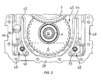
- FIG. 2 is a cross section of the transmission housing 5 in the region of the oil sump 29 shown.
- two housing walls 43, 44 extend from the housing bottom 29 directed upward and form a receiving chamber 45 for receiving the gear 6 of the drive shaft 4 of the transmission 2.
- the receiving chamber 45 is open at the top to allow a meshing of the gear 9 of the intermediate shaft.
- two sump chambers 48, 49 are formed, in which the oil is collected, in each case the oil levels are indicated by the dashed lines 50, 51. Oil that flows into the receiving chamber 45 is thrown upwards by the gear 6 of the drive shaft 4, so that it is thrown over the housing walls 43, 44 and then can flow into the sump chambers 48, 49.
- These serve as calming chambers to prevent the intake of air.
- an inlet opening 52, 53 of the sump chambers 48, 49 in each case an inlet opening 52, 53 of the
- an outlet bore 54 can be seen in the region above one of the sump chambers 48, through which the oil is introduced from the generator sump 40 into the oil sump 29 of the transmission 2.
- a connecting channel 55 is provided, which extends transversely to the drive shaft 4 and in FIG. 1 is recognizable.
Landscapes
- Engineering & Computer Science (AREA)
- General Engineering & Computer Science (AREA)
- Mechanical Engineering (AREA)
- Power Engineering (AREA)
- Chemical & Material Sciences (AREA)
- Combustion & Propulsion (AREA)
- Transportation (AREA)
- General Details Of Gearings (AREA)
- Motor Or Generator Cooling System (AREA)
Applications Claiming Priority (1)
| Application Number | Priority Date | Filing Date | Title |
|---|---|---|---|
| DE102011055192.1A DE102011055192B4 (de) | 2011-11-10 | 2011-11-10 | Generatoreinheit |
Publications (2)
| Publication Number | Publication Date |
|---|---|
| EP2592726A2 true EP2592726A2 (fr) | 2013-05-15 |
| EP2592726A3 EP2592726A3 (fr) | 2017-06-14 |
Family
ID=46963531
Family Applications (1)
| Application Number | Title | Priority Date | Filing Date |
|---|---|---|---|
| EP12185273.5A Withdrawn EP2592726A3 (fr) | 2011-11-10 | 2012-09-20 | Unité de générateur |
Country Status (2)
| Country | Link |
|---|---|
| EP (1) | EP2592726A3 (fr) |
| DE (1) | DE102011055192B4 (fr) |
Cited By (5)
| Publication number | Priority date | Publication date | Assignee | Title |
|---|---|---|---|---|
| DE102014224941A1 (de) * | 2014-12-04 | 2016-06-09 | Volkswagen Aktiengesellschaft | E-Maschinen-Kühlanordnung für einen Kraftfahrzeugantriebsstrang |
| EP3087816A1 (fr) * | 2015-04-30 | 2016-11-02 | Deere & Company | Unite de generateur |
| US20200381984A1 (en) * | 2019-05-31 | 2020-12-03 | MagniX USA, Inc. | High-torque electric motor assembly |
| WO2022252113A1 (fr) * | 2021-06-01 | 2022-12-08 | 舍弗勒技术股份两合公司 | Système d'entraînement de pont |
| US20250079957A1 (en) * | 2019-05-31 | 2025-03-06 | magniX USA Inc. | High-torque electric motor assembly |
Families Citing this family (7)
| Publication number | Priority date | Publication date | Assignee | Title |
|---|---|---|---|---|
| US10404137B2 (en) | 2017-10-24 | 2019-09-03 | Deere & Company | Off-board power and implement coupler for a work vehicle |
| US10948070B2 (en) | 2018-11-13 | 2021-03-16 | Deere & Company | Electric machine lubrication system |
| FR3095092B1 (fr) * | 2019-04-11 | 2021-03-12 | Renault Sas | Dispositif de refroidissement et de lubrification d’un groupe motopropulseur électrique d’un véhicule automobile électrique ou hybride |
| DE102021202522A1 (de) | 2021-03-16 | 2022-09-22 | Zf Friedrichshafen Ag | Vorrichtung zur Kühlung und Schmierung eines Getriebes für ein Fahrzeug |
| DE102021128067A1 (de) | 2021-10-28 | 2023-05-04 | Audi Aktiengesellschaft | Kühlmittelversorgungssystem für eine elektrisch betriebene Fahrzeugachse |
| DE102022109970A1 (de) | 2022-04-26 | 2023-10-26 | Audi Aktiengesellschaft | Getriebemotor für ein Kraftfahrzeug und Kraftfahrzeug mit einem Getriebemotor |
| DE102023117669B4 (de) * | 2023-07-05 | 2025-01-23 | Schaeffler Technologies AG & Co. KG | Elektrisch betreibbarer Achsantriebsstrang |
Citations (1)
| Publication number | Priority date | Publication date | Assignee | Title |
|---|---|---|---|---|
| DE10303050B4 (de) | 2003-01-24 | 2006-05-11 | Gkn Walterscheid Gmbh | Generatoreinheit für Traktoren und elektrisches Antriebssystem für Landmaschinen |
Family Cites Families (9)
| Publication number | Priority date | Publication date | Assignee | Title |
|---|---|---|---|---|
| US4418777A (en) * | 1981-09-11 | 1983-12-06 | Ford Motor Company | Transmission lubrication and motor cooling system |
| US5217085A (en) * | 1992-05-04 | 1993-06-08 | Ford Motor Company | Lubrication and cooling system for a powertrain including an electric motor |
| DE59403962D1 (de) * | 1993-12-23 | 1997-10-09 | Abb Daimler Benz Transp | Kühlsystem für einen Motor |
| US5718302A (en) * | 1994-09-27 | 1998-02-17 | Aisin Aw Co., Ltd. | Hydraulic circuit for electric car drive train |
| JP2005253167A (ja) * | 2004-03-03 | 2005-09-15 | Hitachi Ltd | 車両駆動装置及びそれを用いた電動4輪駆動車両 |
| US20080135339A1 (en) * | 2006-11-17 | 2008-06-12 | Miller Kent A | Method and apparatus for cooling and lubricating an off-axis motor/generator |
| US7798027B2 (en) * | 2007-04-17 | 2010-09-21 | Illinois Tool Works Inc. | Power takeoff and gearbox |
| DK2385612T3 (da) * | 2010-05-06 | 2014-10-13 | Moventas Gears Oy | Elektromekanisk apparat |
| ES2420154T3 (es) * | 2010-05-06 | 2013-08-22 | Moventas Gears Oy | Dispositivo electromecánico |
-
2011
- 2011-11-10 DE DE102011055192.1A patent/DE102011055192B4/de not_active Expired - Fee Related
-
2012
- 2012-09-20 EP EP12185273.5A patent/EP2592726A3/fr not_active Withdrawn
Patent Citations (1)
| Publication number | Priority date | Publication date | Assignee | Title |
|---|---|---|---|---|
| DE10303050B4 (de) | 2003-01-24 | 2006-05-11 | Gkn Walterscheid Gmbh | Generatoreinheit für Traktoren und elektrisches Antriebssystem für Landmaschinen |
Cited By (9)
| Publication number | Priority date | Publication date | Assignee | Title |
|---|---|---|---|---|
| DE102014224941A1 (de) * | 2014-12-04 | 2016-06-09 | Volkswagen Aktiengesellschaft | E-Maschinen-Kühlanordnung für einen Kraftfahrzeugantriebsstrang |
| EP3087816A1 (fr) * | 2015-04-30 | 2016-11-02 | Deere & Company | Unite de generateur |
| US9985499B2 (en) | 2015-04-30 | 2018-05-29 | Deere & Company | Generator unit |
| US20200381984A1 (en) * | 2019-05-31 | 2020-12-03 | MagniX USA, Inc. | High-torque electric motor assembly |
| US12191722B2 (en) * | 2019-05-31 | 2025-01-07 | MagniX USA, Inc. | High-torque electric motor assembly |
| US12244187B2 (en) | 2019-05-31 | 2025-03-04 | MagniX USA, Inc. | Electric propulsion system for delivering high torque |
| US20250079957A1 (en) * | 2019-05-31 | 2025-03-06 | magniX USA Inc. | High-torque electric motor assembly |
| US12391394B2 (en) | 2019-05-31 | 2025-08-19 | magniX USA Inc. | High voltage converter for use as electric power supply |
| WO2022252113A1 (fr) * | 2021-06-01 | 2022-12-08 | 舍弗勒技术股份两合公司 | Système d'entraînement de pont |
Also Published As
| Publication number | Publication date |
|---|---|
| DE102011055192A1 (de) | 2013-05-16 |
| EP2592726A3 (fr) | 2017-06-14 |
| DE102011055192B4 (de) | 2014-05-22 |
Similar Documents
| Publication | Publication Date | Title |
|---|---|---|
| DE102011055192B4 (de) | Generatoreinheit | |
| DE2044441C3 (de) | Aus einem hydrostatisch-mechanischen Überlagerungsgetriebe mit Leistungsverzweigung und einem Generator bestehende Antriebseinheit | |
| EP2831469B1 (fr) | Unité d'entraînement avec échange d'huile | |
| DE102010023948B4 (de) | Elektronische Antriebseinheit | |
| EP4302000B1 (fr) | Système d'alimentation en lubrifiant pour unité d'entraînement d'un véhicule électrique | |
| EP2923120B1 (fr) | Adaptateur de couplage | |
| DE102009017521B4 (de) | Getriebe einer Windenergieanlage | |
| DE102011055194B4 (de) | Hydraulikpumpenanordnung | |
| DE102021207713B3 (de) | Antriebseinheit | |
| DE102011112253A1 (de) | Baueinheit für ein Triebwerk eines Luftfahrzeugs | |
| AT511356A4 (de) | Antriebsstrang für ein fahrzeug | |
| WO2012072351A1 (fr) | Moteur d'entraînement pour système d'entraînement d'appareil de broyage | |
| DE102010051041A1 (de) | Antriebsanordnung | |
| WO2023072445A1 (fr) | Système d'alimentation en liquide de refroidissement pour essieu de véhicule à commande électrique | |
| DE102005003077B4 (de) | Antriebseinheit für ein Kraftfahrzeug | |
| EP3614022A1 (fr) | Transmission hybride | |
| DE102014210774B4 (de) | Hydraulischer Antrieb mit einer verstellbaren hydraulischen Axialkolbenmaschine in Dry-Case Bauweise | |
| DE102015220888A1 (de) | Nebenabtriebskopf | |
| DE10348757A1 (de) | Planetengetriebe | |
| EP3772159A1 (fr) | Unité d'entraînement électromécanique, en particulier unité d'actionnement à roue simple | |
| DE102004032227A1 (de) | Schmierungsstruktur eines Handschaltgetriebes | |
| DE102017213081A1 (de) | Lastschaltgetriebe | |
| WO2021018344A1 (fr) | Unité d'entraînement électrique, module hybride et ensemble d'entraînement pour véhicule automobile | |
| WO2017045759A1 (fr) | Dispositif d'entraînement à filtrage en circulation | |
| DE102011004906A1 (de) | Schmiervorrichtung für ein Achsgetriebe eines Kraftfahrzeugs |
Legal Events
| Date | Code | Title | Description |
|---|---|---|---|
| PUAI | Public reference made under article 153(3) epc to a published international application that has entered the european phase |
Free format text: ORIGINAL CODE: 0009012 |
|
| AK | Designated contracting states |
Kind code of ref document: A2 Designated state(s): AL AT BE BG CH CY CZ DE DK EE ES FI FR GB GR HR HU IE IS IT LI LT LU LV MC MK MT NL NO PL PT RO RS SE SI SK SM TR |
|
| AX | Request for extension of the european patent |
Extension state: BA ME |
|
| PUAL | Search report despatched |
Free format text: ORIGINAL CODE: 0009013 |
|
| AK | Designated contracting states |
Kind code of ref document: A3 Designated state(s): AL AT BE BG CH CY CZ DE DK EE ES FI FR GB GR HR HU IE IS IT LI LT LU LV MC MK MT NL NO PL PT RO RS SE SI SK SM TR |
|
| AX | Request for extension of the european patent |
Extension state: BA ME |
|
| RIC1 | Information provided on ipc code assigned before grant |
Ipc: H02K 7/18 20060101ALN20170511BHEP Ipc: H02K 7/116 20060101ALI20170511BHEP Ipc: B60K 25/06 20060101ALN20170511BHEP Ipc: H02K 9/19 20060101AFI20170511BHEP Ipc: F16H 57/04 20100101ALN20170511BHEP |
|
| STAA | Information on the status of an ep patent application or granted ep patent |
Free format text: STATUS: THE APPLICATION IS DEEMED TO BE WITHDRAWN |
|
| 18D | Application deemed to be withdrawn |
Effective date: 20171215 |