EP2592771A2 - Procédé, dispositif et terminal d'accès aléatoire à une couche physique dans un système de communication mobile tdd à large bande - Google Patents
Procédé, dispositif et terminal d'accès aléatoire à une couche physique dans un système de communication mobile tdd à large bande Download PDFInfo
- Publication number
- EP2592771A2 EP2592771A2 EP13154337.3A EP13154337A EP2592771A2 EP 2592771 A2 EP2592771 A2 EP 2592771A2 EP 13154337 A EP13154337 A EP 13154337A EP 2592771 A2 EP2592771 A2 EP 2592771A2
- Authority
- EP
- European Patent Office
- Prior art keywords
- random access
- physical layer
- frequency
- mobile communication
- sequence
- Prior art date
- Legal status (The legal status is an assumption and is not a legal conclusion. Google has not performed a legal analysis and makes no representation as to the accuracy of the status listed.)
- Granted
Links
Images


Classifications
-
- H—ELECTRICITY
- H04—ELECTRIC COMMUNICATION TECHNIQUE
- H04L—TRANSMISSION OF DIGITAL INFORMATION, e.g. TELEGRAPHIC COMMUNICATION
- H04L5/00—Arrangements affording multiple use of the transmission path
- H04L5/02—Channels characterised by the type of signal
- H04L5/023—Multiplexing of multicarrier modulation signals, e.g. multi-user orthogonal frequency division multiple access [OFDMA]
-
- H—ELECTRICITY
- H04—ELECTRIC COMMUNICATION TECHNIQUE
- H04L—TRANSMISSION OF DIGITAL INFORMATION, e.g. TELEGRAPHIC COMMUNICATION
- H04L5/00—Arrangements affording multiple use of the transmission path
- H04L5/0001—Arrangements for dividing the transmission path
- H04L5/0003—Two-dimensional division
- H04L5/0005—Time-frequency
- H04L5/0007—Time-frequency the frequencies being orthogonal, e.g. OFDM(A) or DMT
-
- H—ELECTRICITY
- H04—ELECTRIC COMMUNICATION TECHNIQUE
- H04L—TRANSMISSION OF DIGITAL INFORMATION, e.g. TELEGRAPHIC COMMUNICATION
- H04L5/00—Arrangements affording multiple use of the transmission path
- H04L5/003—Arrangements for allocating sub-channels of the transmission path
- H04L5/0058—Allocation criteria
- H04L5/006—Quality of the received signal, e.g. BER, SNR, water filling
-
- H—ELECTRICITY
- H04—ELECTRIC COMMUNICATION TECHNIQUE
- H04L—TRANSMISSION OF DIGITAL INFORMATION, e.g. TELEGRAPHIC COMMUNICATION
- H04L5/00—Arrangements affording multiple use of the transmission path
- H04L5/14—Two-way operation using the same type of signal, i.e. duplex
-
- H—ELECTRICITY
- H04—ELECTRIC COMMUNICATION TECHNIQUE
- H04W—WIRELESS COMMUNICATION NETWORKS
- H04W74/00—Wireless channel access
- H04W74/002—Transmission of channel access control information
- H04W74/006—Transmission of channel access control information in the downlink, i.e. towards the terminal
-
- H—ELECTRICITY
- H04—ELECTRIC COMMUNICATION TECHNIQUE
- H04W—WIRELESS COMMUNICATION NETWORKS
- H04W74/00—Wireless channel access
- H04W74/08—Non-scheduled access, e.g. ALOHA
- H04W74/0866—Non-scheduled access, e.g. ALOHA using a dedicated channel for access
Definitions
- the present invention relates to the mobile communication field and in particular to a method, device and terminal for physical layer random access in a wideband time division duplex mobile communication system.
- the TD-SCDMA is the only one which adopts the Time Division Duplex (TDD).
- the TD-SCDMA supports asymmetric service transmission in the uplink and downlink and has more flexibility with respect to the utilization of the frequency spectrum.
- An existing TD-SCDMA system is a system provided with a chip rate of 1.28 Mcps and a bandwidth of 1.6 MHz. The same signal format is used for a data part and uplink and downlink pilot parts of the system.
- Figure 1 illustrates a structural form of a frame in the existing TD-SCDMA system.
- each sub-frame is further divided into seven normal timeslots and three special timeslots.
- the three special timeslots are DwPTS, GP and UpPTS, respectively.
- TSO is usually allocated to the downlink while TS 1 is usually allocated to the uplink.
- An uplink timeslot and a downlink timeslot are separated with a transition point.
- the DwPTS timeslot is intended for transmission of a downlink pilot for an initial search in a cell
- the UpPTS is intended for transmission of an uplink access timeslot for a random access signal
- the GP acts as a guard interval for transition of the downlink timeslot to the uplink timeslot to prevent mutual interference between uplink and downlink channels and has a length which determines the maximum of a coverage radius of the cell.
- terminals enable a random access by sending a random access sequence in the UpPTS timeslot, and the random access sequence may vary from one terminal to another.
- the terminals of all users have to occupy the same frequency band during transmission of the uplink random access sequence due to the bandwidth limitation of the TD-SCDMA system.
- the TD-SCDMA system has to evolve and improve the performance continuously.
- a technical standard for the TD-SCDMA evolvement system is currently being established in the Long Term Evolvement (LTE) research project under the 3GPP organization, and this technical standard is also becoming a predominant technology for the LTE TDD system.
- LTE Long Term Evolvement
- a system enabling a service with a high rate, a large capacity and a broader occupied bandwidth has been proposed in the evolvement solution of the TD-SCDMA and is referred to as a wideband time division duplex cellular system.
- the bandwidth can be up to 200MHz or more, and a terminal can be supported to operate over a frequency band of 1.25 MHz, 2.5 MHz, 5 MHz, 10 MHz and 20 MHz.
- Random access is an important function of a cellular mobile communication system.
- the purpose of the random access is to enable an efficient access of a terminal device in a cellular network to the cellular network, accomplishing allocation of a transmission channel and communication transmission of data.
- a terminal can accomplish synchronization with the system and power control by a random access.
- the terminal can adjust the time to transmit data in accordance with a distance from a base station so as to control the synchronization precision within a cyclic prefix (CP) length, thereby reducing mutual interference between the terminal and other terminals.
- CP cyclic prefix
- the random access enables the base station to control the power of the terminal to transmit a signal in accordance with the distance from the terminal so as to reduce interference between cells.
- the random access is a principal step for the terminal to communicate, and the terminal gains an access to the cellular network system through this process to obtain an uplink channel resource for transmission.
- the random access is implemented by the code division multiple access in the existing TD-SCDMA system
- the increased number of access users may result in a problem that the probability of collision of the random sequences increases since the users may select the same random sequence.
- serious interference between terminals may arise because all the users occupy the same channel resource. Consequently, how to determine a random access mechanism and design a random access channel is a pressing technical problem to be solved.
- the invention provides a method, device and terminal for terminal physical layer random access in a wideband time division duplex mobile communication system to reduce the probability of collision and the interference.
- a method for physical layer random access in a wideband time division duplex mobile communication system in which there is an UpPTS uplink access timeslot for random access including:
- a device for physical layer random access in a wideband time division duplex mobile communication system including:
- a terminal for a wideband time division duplex mobile communication system including a device for physical layer random access including:
- the invention has the following advantages over the prior art.
- the method for physical layer random access in a wideband time division duplex mobile communication system enables different terminals to use different frequency bands since the cell divides the uplink random access channel into several parts in the frequency domain, thereby reducing the probability of competition and collision of the random access sequences transmitted by the terminals, reducing the time required for the access, lowering power consumption of the terminal, and implementing an efficient and rapid random access.
- the invention provides an unprecedented method for physical layer random access with use of the DFT-s OFDM single carrier multiple access in the TDD system.
- Figure 1 illustrates a structural form of a frame in the existing TD-SCDMA and its evolvement system
- Figure 2 illustrates a flow chart of a method for physical layer random access in a wideband time division duplex mobile communication system according to an embodiment of the invention
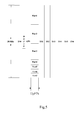
- Figure 3 illustrates a structural diagram of UpPTS timeslot arrangement according to an embodiment of the invention
- Figure 4 illustrates a schematic diagram of UpPTS timeslot frequency band division according to an embodiment of the invention
- Figure 5 illustrates a schematic diagram of UpPTS timeslot frequency band division according to another embodiment of the invention.
- Figure 6 illustrates a schematic diagram of a process of generating a random access sequence by DFT-s OFDM according to an embodiment of the invention
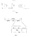
- Figure 7 illustrates a schematic diagram of a structure of the random access sequence generated by DFT-s OFDM
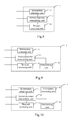
- Figure 8 illustrates a block diagram of a first embodiment of the device according to the invention.
- Figure 9 illustrates a block diagram of a second embodiment of the device according to the invention.
- Figure 10 illustrates a block diagram of a third embodiment of the device according to the invention.
- the existing TD-SCDMA system with a bandwidth of 1.6 MHz may share some frequency bands with its evolvement system, and base stations of the systems may need to be co-located.
- a preferable option is to make frame structures of the two systems consistent in so far as possible.
- Figure 1 illustrates a schematic diagram of the same frame structure used for the two systems, and reference can be made to various disclosed documents or technical references of standards for names and functions of specific timeslots.
- the invention is not limited to the above frame structure, such as parameters of the number and the length of timeslots, but intended to provide a method for random access dependent upon a stipulation of the design and usage of the UpPTS timeslot in the frame structure.
- Figure 2 illustrates a flow chart of a method for physical layer random access in a wideband time division duplex mobile communication system according to an embodiment of the invention.
- a terminal receives a system broadcast message of a cell and obtains configuration information in the frequency domain of the UpPTS timeslot of the cell.
- the system can support scaleable frequency band width configuration of, e.g., 5 MHz, 10 MHz, 15 MHz, 20 MHz, etc., or even smaller frequency bands of, e.g., 1.25 MHz, 2.5 MHz, etc.
- a cell supports different frequency band widths in different network development phrases, and supported frequency band widths vary from one cell to another.
- a frequency band width of a random access sequence transmitted by the terminal during a random access can be defined within a frequency band, thereby making best use of a device capability of the terminal.
- the entire frequency band width of the UpPTS timeslot can either be divided equally or be divided into frequency bands with different bandwidths.
- the frequency band is divided for each cell in view of factors of an access capability of the terminal and the like.
- the configuration information of the UpPTS timeslot in the frequency domain particularly refers to information on the number of frequency bands into which the entire used bandwidth is divided for the UpPTS timeslot, information on bandwidths of the respective frequency bands, and information on frequency point locations of the respective frequency bands.
- the information can be broadcast in a system broadcast message throughout a coverage range of the cell, and the terminal can know the resource configuration of the UpPTS timeslot of the cell where it resides by receiving the system broadcast message and thereby can initiate a random access at any time. Division of the UpPTS timeslot in the frequency domain will be further discussed in following descriptions of the embodiments of the invention.
- the terminal selects a frequency band in accordance with a measurement result of signal-to-noise ratios or reception powers of a downlink pilot channel. Since the TD-SCDMA evolvement system uses a relatively broad bandwidth, its pilot signal is transmitted throughout the entire frequency band width. Due to frequency selectivity of a wireless propagation environment, magnitudes of powers of the pilot signal received by the terminal may vary from one sub-frequency band to another. By measuring the signal-to-noise ratios and the received signal powers of the downlink pilot channel, a frequency band with better signal quality can be selected for an uplink random access, thereby guaranteeing good performance of the random access. The frequency band can also be selected in combination with an access capability of the terminal.
- UpPTS frequency band division can be established in advance.
- the service initiating terminal which requires a random access can select a corresponding frequency band in accordance with the service priority of a service to be initiated or the access priority of the terminal.
- the above two approaches can be combined to provide a more versatile random access function.
- a frequency band can be selected randomly.
- the terminal selects randomly a frequency band among three 5 MHz frequency bands for transmission of a random access sequence.
- the terminal can determine a frequency band with the best frequency selectivity attenuation performance by measuring a downlink plot channel transmitted from the base station and transmit over this frequency band. For example, the terminal determines from a measurement result that the frequency band of Part3 has the best transmission quality and thus selects the frequency band of Part3 over which a random access sequence is transmitted.
- the terminal can select a sub-band channel of 5 MHz as an uplink random access channel in accordance with a terminal capability of the user (where a transmission bandwidth of the terminal is 5 MHz).
- the maximum number of transmissions and a predetermined time are set.
- the terminal will wait for a response message from the base station after transmitting the random access sequence to the base station to determine whether the access succeeds. If no response message from the base station is received, the random access sequence is typically retransmitted.
- the maximum number of transmissions is a limitation on the number of transmissions. When the number of transmissions is beyond the maximum number of transmissions, the terminal will not transmit the random access sequence any longer. Furthermore, the terminal may receive no response message after transmitting the random access sequence. At this time, the parameter of the predetermined period can be used to determine whether the random access sequence has been received by the base station after it is transmitted.
- the terminal After selecting the corresponding access frequency band, the terminal transmits the random access sequence to the base station over the selected frequency band in the step 204. Prior to this, the terminal also selects the random access sequence.
- the random access sequence is generated in a specific way. For example, the random access sequence is generated from a single carrier by DFT-s OFDM or a traditional carrier. Each transmitted random access sequence represents a different terminal.
- the terminal selects a random access sequence from a set of random access sequences for transmission. The selection may be made in accordance with the priority of the random access sequence.
- the power to transmit the sequence can be obtained by measuring the downlink pilot signal, and the initial power for transmission can be obtained in view of symmetry of the channel.
- the terminal After the transmission, the terminal will receive a response message from the base station.
- the response message is made by the base station upon reception of the random access sequence transmitted from the terminal.
- the base station processes the received random access sequence as follows.
- the base station Upon reception of the random access sequence transmitted from the terminal, the base station firstly matches and filters the received random access sequence with a set of codes to make a determination on the random access sequence transmitted from the terminal. Then, after the random access sequence transmitted from the terminal has been determined, the received random access sequence is interpolated, and an uplink synchronization deviation of the terminal is obtained, so that the terminal is instructed to adjust the temporal deviation in the response message transmitted to the terminal. Finally, the received random access sequence is detected, and it is determined whether there is a terminal which uses the same random access sequence for access. That is, collision detection is made. If a collision is detected, it proceeds with a collision processing flow. The collision processing flow will be described in details below.
- the base station may or may not transmit a response message to the terminal. For example, when the base station does not detect a collision, the base station can transmit to the terminal an affirmative response message indicating a success of the access and instruct the terminal to make a further adjustment on transmission of signal. When the base station detects a collision, the base station may not transmit a response message to the terminal and instead wait for retransmission from the terminal. If resources of the system are currently insufficient and no further access request can be accepted, the base station can transmit to the terminal a negative response message indicating a failure of the access. Particularly, the transmitted response message includes synchronization information and power control information.
- the terminal determines whether a response message from the base station is received within the predetermined period. If no response message from the base station is received within the predetermined period (e.g., 5 ms), then in the step 207, the terminal queries a counter which counts the number of times that the random access sequence is transmitted.
- the counter can be implemented by a software or hardware logic unit arranged in the terminal. The counter stores the number of times that the random access sequence is transmitted during the current uplink random access. When the number of transmissions is beyond the predetermined maximum number of transmissions, the system will not retransmit the random access any longer. Meanwhile, in the step 209, the terminal will determine a failure of the current physical layer random access.
- the terminal retransmits the random access sequence in the step 208.
- a period of time will elapse prior to the retransmission to avoid collisions with other terminals.
- a response message from the base station is received within the predetermined period, it is further determined in the step 206 whether the received response message from the base station is an affirmative response message or not.
- the affirmative or negative response message is determined dependent upon a transmission protocol between the terminal and the base station. If the received response message is an affirmative response message, that is, the base station can communicate with the terminal transmitting the random access sequence code, then in the step 210, the terminal determines a success of the current physical layer random access and further proceeds with a subsequent process.
- the terminal determines a failure of the current physical layer random access and also further proceeds with a corresponding subsequent process.
- the descriptions above are illustrative of the entire process for a physical layer random access of the terminal.
- a power increment step is set.
- the terminal increments the power to transmit the random access sequence by the magnitude of one step upon each retransmission, so that the power for each retransmission will be higher than that for previous transmission, thereby avoiding a disability of the base station to receive the random access sequence duo to insufficient power.
- FIG. 3 illustrates a structural diagram of UpPTS timeslot arrangement according to an embodiment of the invention.
- the UpPTS timeslot is arranged in the wideband timeslot duplex cellular system according to the invention.
- the UpPTS timeslot includes two parts: one part is a random access sequence transmission period and the other is a guard period.
- the random access sequence transmission period is intended for transmission of the random access sequence selected by the terminal, and the guard period is intended for adjusting the random access sequence transmission period.
- the terminal can not determine accurately the time that the random access sequence reaches the base station because the distance of the terminal from the base station varies.
- the random access sequence transmission period can be adjusted within the guard period to satisfy the synchronization requirement.
- the bandwidth of the UpPTS timeslot in the frequency domain can be divided into several parts each provided with a frequency bandwidth of 1.25 MHz.
- different users can send a random access sequence to the base station over different frequency bands.
- Figure 4 illustrates a schematic diagram of UpPTS timeslot bandwidth division according to an embodiment of the invention.
- the transmission bandwidth of the system is 5 MHz.
- the 5 MHz bandwidth in the UpPTS timeslot is divided equally into four parts each provided with a sub-band width of 1.25 MHz.
- a user in this cell can transmit a random access sequence for a random access over any sub-band width in the UpPTS timeslot.
- a random channel can be selected randomly among random channels with the same sub-band width.
- the terminal can select a sub-band with the best frequency selectivity attenuation performance by measuring a downlink plot channel transmitted from the base station and transmit over the selected sub-band channel.
- Figure 5 illustrates a schematic diagram of UpPTS timeslot bandwidth division according to another embodiment of the invention.
- resources in its UpPTS timeslot can be divided into several different frequency bands in the frequency domain.
- the width of the frequency band may be 1.25 MHz or 5 MHz.
- Figure 5 illustrates a schematic diagram of an embodiment for a system bandwidth of 20 MHz.
- resources of the UpPTS timeslot are divided into seven parts in the frequency domain, where Part1 to Part 3 denote frequency bands with a bandwidth of 5 MHz, and Part4 to Part7 denote frequency bands with a bandwidth of 1.25 MHz.
- a terminal in the cell can select the sub-band of 5 MHz or 1.25 MHz for transmission of a random access sequence in accordance with capability of the terminal. For example, the terminal enabling 5 MHz transmission can select the frequency band with the bandwidth of either 5 MHz or 1.25 MHz for a random access.
- the terminal When a random sequence is transmitted over the frequency band with the bandwidth of 5 MHz, the reception and determination performance of the base station can be enhanced, the power of the terminal to transmit a random access sequence is reduced, and power consumption and interference with an adjacent cell of the terminal is reduced. Therefore, the terminal typically selects the frequency band with the bandwidth of 5 MHz preferably as an uplink random access channel.
- Figure 6 illustrates a schematic diagram of a process of generating a random access sequence by DFT-s OFDM according to an embodiment of the invention.
- a random access sequence for the UpPTS timeslot illustrated in Figure 3 can be generated from a single carrier by DFT-s OFDM or a traditional signal carrier.
- a method for generating random access sequence is as illustrated in the figure.
- the random sequence is transformed into a frequency-domain signal after a DFT process.
- the generated random sequence can be selected by the terminal as a random access sequence transmitted to the base station over a corresponding frequency band of the UpPTS timeslot.
- a random access sequence transmitted over a random access sub-channel with a different bandwidth can be of a different length to adapt a corresponding bandwidth resource.
- the lengths of the random access sequences transmitted over the random access sub-channels with frequency bandwidths of 1.25 MHz and 5 MHz are different.
- the length of the random access sequence transmitted over the sub-band channel of 5 MHz is 4 times that of 1.25 MHz.
- Figure 7 illustrates a schematic diagram of a structure of a random access sequence generated by DFT-s OFDM. If a random access sequence is generated by DFT-s OFDM, a structure of the UpPTS timeslot illustrated in Figure 7 can be designed.
- the random access sequence consists of SB and LB generated respectively by DFT-s OFDM, where the SB denotes a short block and the LB denotes a long block.
- the length of the SB is a half of that of the LB. This is because the length of IFFT used to generate the SB sequence is a half of that of IFFT for the LB. As illustrated in Figure 7 , the length of the SB is 33.3 ⁇ s and that of the LB is 66.6 ⁇ s.
- the random access sequence includes no CP (i.e., Cyclic Prefix) in this embodiment, but may include a CP in other embodiments.
- FIG. 8 illustrates a block diagram of a first embodiment of the device according to the invention.
- the device 1 makes use of the UpPTS timeslot for a random access.
- the device 1 includes the following units.
- An information obtaining unit 11 is adapted to receive a system broadcast message of a cell and to obtain configuration information on the UpPTS timeslot of the cell in the frequency domain.
- An access sequence transmitting unit 12 is adapted to transmit a random access sequence to a base station in the UpPTS timeslot in accordance with the configuration information on the UpPTS timeslot in the frequency domain obtained from the information obtaining unit.
- a network accessing unit 13 is adapted to receive a response message from the base station; and if no response message from the base station is received within a predetermined period, the terminal retransmits the random access sequence, and if a response message is received within the predetermined period, the terminal proceeds with a subsequent processing flow for the random access.
- Figure 9 illustrates a block diagram of a second embodiment of the device according to the invention.
- the embodiment in Figure 9 is different from that in Figure 8 in that this embodiment further includes a determining unit 14 adapted to determine whether the number of times that the random access sequence is transmitted exceeds the maximum number of transmissions; and if the maximum number of transmissions is not exceeded, the terminal retransmits the random access sequence, and if the maximum number of transmissions is exceeded, a failure of the current physical layer random access is determined.
- Figure 10 illustrates a block diagram of a third embodiment according to the invention.
- the embodiment in Figure 10 is different from that in Figure 9 in that this embodiment further includes an information processing unit 15 adapted to select a frequency band in accordance with a measurement result of signal-to-noise ratios or reception powers of a downlink pilot channel and to instruct the access sequence transmitting unit to transmit the random access sequence over the frequency band.
- an information processing unit 15 adapted to select a frequency band in accordance with a measurement result of signal-to-noise ratios or reception powers of a downlink pilot channel and to instruct the access sequence transmitting unit to transmit the random access sequence over the frequency band.
- the information processing unit 15 can alternatively be configured to select a corresponding frequency band in accordance with service priority of its service to be initiated or its access priority and to instruct the access sequence transmitting unit to transmit the random access sequence over the frequency band.
- the physical layer random access device in the terminal includes the following units.
- An information obtaining unit is adapted to receive a system broadcast message of a cell and to obtain configuration information on the UpPTS timeslot of the cell in the frequency domain.
- An access sequence transmitting unit is adapted to transmit a random access sequence to a base station in the UpPTS timeslot in accordance with the configuration information on the UpPTS timeslot in the frequency domain obtained from the information obtaining unit.
- a network accessing unit is adapted to receive a response message from the base station; and if no response message from the base station is received within a predetermined period, the terminal retransmits the random access sequence, and if a response message is received within the predetermined period, the terminal proceeds with a subsequent processing flow for the random access.
- the terminal may have further improved performance.
Landscapes
- Engineering & Computer Science (AREA)
- Signal Processing (AREA)
- Computer Networks & Wireless Communication (AREA)
- Quality & Reliability (AREA)
- Mobile Radio Communication Systems (AREA)
Applications Claiming Priority (3)
| Application Number | Priority Date | Filing Date | Title |
|---|---|---|---|
| CN200610005674A CN101005308B (zh) | 2006-01-17 | 2006-01-17 | 宽带时分双工移动通信系统的物理层随机接入方法 |
| EP07701947A EP1981188A4 (fr) | 2006-01-17 | 2007-01-04 | Procédé, dispositif et terminal d'accès aléatoire à une couche physique dans un système de communication mobile tdd à large bande |
| PCT/CN2007/000015 WO2007082458A1 (fr) | 2006-01-17 | 2007-01-04 | Procédé, dispositif et terminal d'accès aléatoire à une couche physique dans un système de communication mobile tdd à large bande |
Related Parent Applications (2)
| Application Number | Title | Priority Date | Filing Date |
|---|---|---|---|
| EP07701947.9 Division | 2007-01-04 | ||
| EP07701947A Division EP1981188A4 (fr) | 2006-01-17 | 2007-01-04 | Procédé, dispositif et terminal d'accès aléatoire à une couche physique dans un système de communication mobile tdd à large bande |
Publications (3)
| Publication Number | Publication Date |
|---|---|
| EP2592771A2 true EP2592771A2 (fr) | 2013-05-15 |
| EP2592771A3 EP2592771A3 (fr) | 2014-11-26 |
| EP2592771B1 EP2592771B1 (fr) | 2019-02-13 |
Family
ID=38287256
Family Applications (2)
| Application Number | Title | Priority Date | Filing Date |
|---|---|---|---|
| EP13154337.3A Active EP2592771B1 (fr) | 2006-01-17 | 2007-01-04 | Procédé, dispositif et terminal d'accès aléatoire à une couche physique dans un système de communication mobile tdd à large bande |
| EP07701947A Ceased EP1981188A4 (fr) | 2006-01-17 | 2007-01-04 | Procédé, dispositif et terminal d'accès aléatoire à une couche physique dans un système de communication mobile tdd à large bande |
Family Applications After (1)
| Application Number | Title | Priority Date | Filing Date |
|---|---|---|---|
| EP07701947A Ceased EP1981188A4 (fr) | 2006-01-17 | 2007-01-04 | Procédé, dispositif et terminal d'accès aléatoire à une couche physique dans un système de communication mobile tdd à large bande |
Country Status (6)
| Country | Link |
|---|---|
| US (1) | US8072932B2 (fr) |
| EP (2) | EP2592771B1 (fr) |
| JP (1) | JP4997577B2 (fr) |
| KR (1) | KR101050522B1 (fr) |
| CN (2) | CN102724766B (fr) |
| WO (1) | WO2007082458A1 (fr) |
Cited By (1)
| Publication number | Priority date | Publication date | Assignee | Title |
|---|---|---|---|---|
| EP3247156A4 (fr) * | 2015-02-12 | 2018-02-21 | Huawei Technologies Co., Ltd. | Dispositif, système et procédé d'émission de signal |
Families Citing this family (57)
| Publication number | Priority date | Publication date | Assignee | Title |
|---|---|---|---|---|
| TWI355164B (en) * | 2007-02-27 | 2011-12-21 | Quanta Comp Inc | Data transmitting method for wireless communicatio |
| CN101369840B (zh) * | 2007-08-13 | 2012-07-04 | 电信科学技术研究院 | 时分双工随机接入方法、系统及其组成模块 |
| KR101433939B1 (ko) * | 2007-09-13 | 2014-08-26 | 삼성전자주식회사 | 가시광 통신을 이용한 무선 랜 시스템에서 데이터 재전송방법 및 장치 |
| CN101128063B (zh) * | 2007-09-24 | 2012-05-09 | 中兴通讯股份有限公司 | 终端随机接入蜂窝无线通讯系统的方法及群标识生成方法 |
| CN110087317B (zh) * | 2007-09-28 | 2021-01-05 | 无线创新信号信任公司 | Wtru、wtru执行的方法、基站执行的方法以及装置 |
| CN101400157B (zh) * | 2007-09-29 | 2010-12-01 | 中国移动通信集团公司 | 一种通信方法和装置 |
| CN101414902B (zh) * | 2007-10-16 | 2010-05-12 | 大唐移动通信设备有限公司 | 长期演进时分双工系统的传输方法及装置 |
| CN101159476B (zh) * | 2007-10-29 | 2014-03-19 | 中兴通讯股份有限公司 | 物理随机接入信道发送方法 |
| CN101159478B (zh) * | 2007-10-29 | 2012-12-19 | 中兴通讯股份有限公司 | 物理随机信道发送方法 |
| CN101426272B (zh) * | 2007-11-02 | 2010-06-02 | 大唐移动通信设备有限公司 | 导频资源分配方法、系统和设备 |
| EP2215727B1 (fr) * | 2007-11-06 | 2017-03-29 | Telefonaktiebolaget LM Ericsson (publ) | Unité de communications et procédé d'utilisation associé |
| CN101162986B (zh) * | 2007-11-09 | 2011-12-07 | 中兴通讯股份有限公司 | 一种时分双工系统下行特殊时隙上的信号发送方法 |
| CN101162987B (zh) * | 2007-11-10 | 2011-06-22 | 中兴通讯股份有限公司 | 一种时分双工系统上行特殊时隙中导频信号的发送方法 |
| ES2373869T3 (es) * | 2007-12-12 | 2012-02-09 | Telefonaktiebolaget L M Ericsson (Publ) | Configuración del acceso aleatorio extendido transmitido por una estación de base de una e-utran para el acceso aleatorio de un equipo de usuario a un canal de radio. |
| CN101197588B (zh) * | 2007-12-26 | 2013-01-16 | 中兴通讯股份有限公司 | 用于无线通信系统的导频符号发送方法和装置 |
| CN103347287B (zh) | 2008-01-02 | 2017-03-01 | 交互数字专利控股公司 | Wtru以及与wtru相关联的小区重选的方法 |
| CN101483915B (zh) * | 2008-01-07 | 2012-06-27 | 三星电子株式会社 | 传输随机接入前导信号的设备和方法 |
| CN101217808B (zh) | 2008-01-17 | 2013-01-16 | 中兴通讯股份有限公司 | 无线通信系统中随机接入信号的发送方法 |
| CN101500242B (zh) * | 2008-02-01 | 2010-10-27 | 大唐移动通信设备有限公司 | 一种配置上行探测参考信号的方法和装置 |
| CN101252386B (zh) | 2008-03-26 | 2013-06-05 | 中兴通讯股份有限公司 | 物理随机接入信道的映射方法 |
| CN101568165B (zh) * | 2008-04-25 | 2011-11-16 | 电信科学技术研究院 | 一种上行信号处理方法、系统和装置 |
| ES2556975T3 (es) * | 2008-05-16 | 2016-01-21 | Telefonaktiebolaget Lm Ericsson (Publ) | Método para un receptor de espectro agregado de radio único, programa informático, receptor y terminal |
| CN101340725B (zh) * | 2008-08-07 | 2012-07-18 | 中兴通讯股份有限公司 | 一种物理随机接入信道的资源分配方法 |
| CN101668327B (zh) * | 2008-09-04 | 2012-02-01 | 电信科学技术研究院 | 一种随机接入过程的发起方法、系统及设备 |
| KR101335745B1 (ko) * | 2009-04-24 | 2013-12-02 | 노키아 코포레이션 | 통신을 위한 부분 지원을 갖는 액세스 제어 |
| CN101998607B (zh) * | 2009-08-31 | 2013-07-31 | 中国移动通信集团公司 | 上行时隙引入下行传输辅同步信号的方法、系统及装置 |
| CN102113402A (zh) * | 2009-10-07 | 2011-06-29 | 高通股份有限公司 | 用于避免物理随机接入信道冲突的方法和装置 |
| CN102100101B (zh) * | 2009-10-14 | 2014-03-19 | 高通股份有限公司 | 时分同步码分多址(td-scdma)网络中传输失败检测的方法和装置 |
| CN102687550B (zh) | 2009-12-24 | 2016-08-03 | 日本电气株式会社 | 中继设备、中继系统、中继方法、无线电通信系统以及程序 |
| US8666398B2 (en) | 2010-04-13 | 2014-03-04 | Qualcomm Incorporated | Random access procedure enhancements for heterogeneous networks |
| CN102223730B (zh) * | 2010-04-14 | 2015-04-22 | 电信科学技术研究院 | 一种辅载波随机接入失败的处理方法及装置 |
| JP2012004997A (ja) * | 2010-06-18 | 2012-01-05 | Kyocera Corp | 無線通信システム、無線基地局、及び消費電力制御方法 |
| US9084262B2 (en) * | 2010-07-22 | 2015-07-14 | Qualcomm Incorporated | Coordinating transmission hold and resume in TD-SCDMA |
| CN102300267A (zh) * | 2011-09-28 | 2011-12-28 | 电信科学技术研究院 | 一种确定终端工作带宽的方法及终端 |
| CN103249167B (zh) | 2012-02-01 | 2016-12-21 | 华为技术有限公司 | 物理随机接入信道接入方法、基站和用户设备 |
| US9918315B2 (en) * | 2013-08-16 | 2018-03-13 | Sony Corporation | Telecommunications apparatus and methods |
| JP2016533053A (ja) | 2013-10-08 | 2016-10-20 | 華為技術有限公司Huawei Technologies Co.,Ltd. | オープン発見リソースとセルラリソースとの衝突を回避する方法 |
| CN103731888B (zh) * | 2014-01-26 | 2017-06-23 | 北京睿仁医疗科技有限公司 | 无线通讯方法、通讯装置及其通讯系统 |
| WO2015109609A1 (fr) * | 2014-01-27 | 2015-07-30 | 华为技术有限公司 | Procédé de transmission en bande étroite, dispositif, station de base, et équipement d'utilisateur |
| CN104219780B (zh) * | 2014-09-26 | 2018-01-12 | 上海交通大学 | 一种支持全双工ofdma的随机接入介质访问控制方法 |
| CN107113871B (zh) * | 2014-12-31 | 2021-01-08 | 瑞典爱立信有限公司 | 对ue到中继ap的随机接入进行定时 |
| CN104993858B (zh) * | 2015-06-01 | 2018-07-20 | 武汉拓宝科技股份有限公司 | 一种tdd通信方法 |
| CN117062227A (zh) * | 2016-11-04 | 2023-11-14 | 中兴通讯股份有限公司 | 无线通信方法、设备、节点以及计算机可读程序存储介质 |
| CN108111990B (zh) * | 2016-11-11 | 2020-12-25 | 中国电信股份有限公司 | 用于提升上行容量的信息传输方法和系统 |
| MX2019008092A (es) * | 2017-01-05 | 2019-09-04 | Guangdong Oppo Mobile Telecommunications Corp Ltd | Metodo para acceso aleatorio y dispositivo terminal. |
| CN109041228B (zh) * | 2017-06-12 | 2021-03-12 | 维沃移动通信有限公司 | 信息传输方法、基站、移动终端及计算机可读存储介质 |
| CN109152085B (zh) * | 2017-06-16 | 2023-01-13 | 华为技术有限公司 | 随机接入方法、设备及系统 |
| KR102286050B1 (ko) * | 2017-06-23 | 2021-08-03 | 현대자동차주식회사 | 차량 네트워크에서 진단 오류 방지를 위한 방법 및 장치 |
| CN109219132B (zh) * | 2017-06-29 | 2021-02-09 | 华为技术有限公司 | 信道选择方法与装置 |
| CN110832935B (zh) | 2017-08-10 | 2023-06-06 | 富士通株式会社 | 分配和接收频域资源的方法、装置及通信系统 |
| CN109587792B (zh) * | 2017-09-29 | 2021-03-02 | 华为技术有限公司 | 探测参考信号的资源分配方法及装置 |
| CN109803396B (zh) * | 2017-11-17 | 2024-09-10 | 华为技术有限公司 | 资源分配的方法和装置 |
| CN110474735B (zh) * | 2018-05-11 | 2021-03-23 | 华为技术有限公司 | 通信方法和通信装置 |
| CN110677910B (zh) * | 2018-07-03 | 2022-08-19 | 珠海市魅族科技有限公司 | 初始接入资源的分配方法及初始接入资源的获取方法 |
| CN114696972B (zh) * | 2020-12-28 | 2024-11-22 | 广州慧睿思通科技股份有限公司 | Prach检测方法、高层物理层模块、装置和设备 |
| CN116801390A (zh) * | 2022-03-10 | 2023-09-22 | 展讯半导体(南京)有限公司 | 时隙配置方法及设备 |
| US12532337B2 (en) | 2023-08-31 | 2026-01-20 | T-Mobile Usa, Inc. | Frequency layer management using OTA performance tests of a mobile device |
Family Cites Families (15)
| Publication number | Priority date | Publication date | Assignee | Title |
|---|---|---|---|---|
| US6185409B1 (en) * | 1995-11-30 | 2001-02-06 | Amsc Subsidiary Corporation | Network engineering/systems engineering system for mobile satellite communication system |
| EP0841763B1 (fr) * | 1996-10-25 | 2003-12-10 | Nokia Corporation | Procédé de contrôle de ressources radio |
| JP2001268051A (ja) * | 2000-03-22 | 2001-09-28 | Ntt Docomo Inc | マルチキャリア/ds−cdma移動通信システムにおける上りリンクパケット伝送方法 |
| DE10008653A1 (de) | 2000-02-24 | 2001-09-06 | Siemens Ag | Verbesserungen an einem Funkkommunikationssystem |
| WO2001072080A1 (fr) * | 2000-03-23 | 2001-09-27 | Siemens Information And Communication Networks S.P.A. | Programmation de canal d'acces dans un systeme de radiocommunication |
| US7630346B2 (en) * | 2000-09-29 | 2009-12-08 | Intel Corporation | Hopping on random access channels |
| KR100662283B1 (ko) | 2000-11-20 | 2007-01-02 | 엘지전자 주식회사 | 시분할 듀플렉스 모드에서의 랜덤 액세스 방법 |
| US6842803B2 (en) * | 2001-07-09 | 2005-01-11 | Advanced Micro Devices, Inc. | Computer system with privileged-mode modem driver |
| JP4067873B2 (ja) * | 2002-05-24 | 2008-03-26 | 三菱電機株式会社 | 無線伝送装置 |
| CN1497882B (zh) * | 2002-10-23 | 2010-04-07 | 华为技术有限公司 | 一种时分双工系统的随机接入方法 |
| ES2985074T3 (es) * | 2004-03-09 | 2024-11-04 | Optis Wireless Technology Llc | Procedimiento de acceso aleatorio y dispositivo terminal de radiocomunicación |
| JP2005341432A (ja) * | 2004-05-28 | 2005-12-08 | Ntt Docomo Inc | 周波数選択装置、移動通信システムおよびマルチバンド制御方法 |
| CN100512535C (zh) * | 2004-07-09 | 2009-07-08 | 中兴通讯股份有限公司 | 一种td-scdma系统多载频覆盖的随机接入方法 |
| US20060099733A1 (en) | 2004-11-09 | 2006-05-11 | Geefay Frank S | Semiconductor package and fabrication method |
| US8149969B2 (en) * | 2005-10-07 | 2012-04-03 | Samsung Electronics Co., Ltd. | Apparatus and method for reduced peak-to-average-power ratio in a wireless network |
-
2006
- 2006-01-17 CN CN201210223457.XA patent/CN102724766B/zh not_active Expired - Lifetime
- 2006-01-17 CN CN200610005674A patent/CN101005308B/zh not_active Expired - Lifetime
-
2007
- 2007-01-04 JP JP2008550612A patent/JP4997577B2/ja active Active
- 2007-01-04 US US12/161,310 patent/US8072932B2/en active Active
- 2007-01-04 EP EP13154337.3A patent/EP2592771B1/fr active Active
- 2007-01-04 EP EP07701947A patent/EP1981188A4/fr not_active Ceased
- 2007-01-04 WO PCT/CN2007/000015 patent/WO2007082458A1/fr not_active Ceased
- 2007-01-04 KR KR1020087020180A patent/KR101050522B1/ko active Active
Non-Patent Citations (1)
| Title |
|---|
| None |
Cited By (3)
| Publication number | Priority date | Publication date | Assignee | Title |
|---|---|---|---|---|
| EP3247156A4 (fr) * | 2015-02-12 | 2018-02-21 | Huawei Technologies Co., Ltd. | Dispositif, système et procédé d'émission de signal |
| US10555277B2 (en) | 2015-02-12 | 2020-02-04 | Huawei Technologies Co., Ltd. | Signal transmission apparatus, system, and method |
| US11057867B2 (en) | 2015-02-12 | 2021-07-06 | Huawei Technologies Co., Ltd. | Signal transmission apparatus, system, and method |
Also Published As
| Publication number | Publication date |
|---|---|
| KR101050522B1 (ko) | 2011-07-20 |
| EP1981188A1 (fr) | 2008-10-15 |
| CN101005308B (zh) | 2012-08-29 |
| EP2592771A3 (fr) | 2014-11-26 |
| JP4997577B2 (ja) | 2012-08-08 |
| CN101005308A (zh) | 2007-07-25 |
| EP2592771B1 (fr) | 2019-02-13 |
| EP1981188A4 (fr) | 2010-04-14 |
| CN102724766A (zh) | 2012-10-10 |
| US8072932B2 (en) | 2011-12-06 |
| US20100226295A1 (en) | 2010-09-09 |
| KR20080096550A (ko) | 2008-10-30 |
| JP2009524303A (ja) | 2009-06-25 |
| WO2007082458A1 (fr) | 2007-07-26 |
| CN102724766B (zh) | 2016-03-16 |
Similar Documents
| Publication | Publication Date | Title |
|---|---|---|
| US8072932B2 (en) | Method, device, and terminal for physical layer random access in wideband TDD mobile communication system | |
| US10306682B2 (en) | Device and method for transmitting random access preamble | |
| EP3306996B1 (fr) | Procédé de transmission de données, dispositif de réseau sans fil et système de communication | |
| EP3420772B1 (fr) | Structure de trame flexible destinée à des systèmes ofdm | |
| EP3103305B1 (fr) | Système et procédé pour réserver un canal pour la coexistence d'u-lte et de wi-fi | |
| EP3163967B1 (fr) | Procédé et dispositif pour émettre des données dans une bande sans licence | |
| EP2223563B1 (fr) | Identification de procédure de mesure de distance d'un terminal sans fil amélioré | |
| EP2797355A1 (fr) | Procédé et appareil de communication sans fil | |
| EP3378185A1 (fr) | Signalisation de signaux puchh courts | |
| US20160174067A1 (en) | Ranging Procedure Identification of Enhanced Wireless Terminal | |
| JP2009503958A (ja) | 時分割複信移動通信システムの伝送方法 | |
| WO2020068616A1 (fr) | Accès multiple avec écoute de porteuse et classe de priorité d'accès au canal pour rach dans une nouvelle radio sans licence | |
| US20250351169A1 (en) | Continuous transmission for new radio-unlicensed (nr-u) uplink | |
| US20120082071A1 (en) | System Compatibility Method and Apparatus | |
| WO2008045645A2 (fr) | Système de communication et son procédé de fonctionnement | |
| CN100388647C (zh) | 多载波系统上行同步及用户设备接入方法 | |
| CN113711684A (zh) | 基站、终端、无线通信系统 | |
| CN106059978A (zh) | 免许可频段下蜂窝移动通信系统的帧结构及通信协议 | |
| CN101087469B (zh) | 一种实现用户设备随机接入的方法 | |
| CN101472283A (zh) | 移动通信共享系统、基站装置、和基站装置的控制方法 | |
| CN113133120A (zh) | 通信调度方法、系统及终端、基站设备 | |
| EP4583476A1 (fr) | Appareil et procédé pour améliorer la couverture dans un système de communication sans fil | |
| US20240381426A1 (en) | Demodulation reference signal (dm-rs) patterns and scrambling sequences for physical sidelink control channel (pscch) or physical sidelink shared channel (pssch) transmissions with multiple starting symbols | |
| CN100579315C (zh) | 用户站接入移动无线系统网络的方法 |
Legal Events
| Date | Code | Title | Description |
|---|---|---|---|
| PUAI | Public reference made under article 153(3) epc to a published international application that has entered the european phase |
Free format text: ORIGINAL CODE: 0009012 |
|
| AC | Divisional application: reference to earlier application |
Ref document number: 1981188 Country of ref document: EP Kind code of ref document: P |
|
| AK | Designated contracting states |
Kind code of ref document: A2 Designated state(s): DE FR GB |
|
| RIC1 | Information provided on ipc code assigned before grant |
Ipc: H04L 5/02 20060101ALI20140702BHEP Ipc: H04W 74/00 20090101ALI20140702BHEP Ipc: H04W 74/08 20090101ALI20140702BHEP Ipc: H04L 5/00 20060101ALI20140702BHEP Ipc: H04J 3/06 20060101AFI20140702BHEP |
|
| PUAL | Search report despatched |
Free format text: ORIGINAL CODE: 0009013 |
|
| AK | Designated contracting states |
Kind code of ref document: A3 Designated state(s): DE FR GB |
|
| RIC1 | Information provided on ipc code assigned before grant |
Ipc: H04J 3/06 20060101AFI20141021BHEP Ipc: H04L 5/02 20060101ALI20141021BHEP Ipc: H04W 74/08 20090101ALI20141021BHEP Ipc: H04W 74/00 20090101ALI20141021BHEP Ipc: H04L 5/00 20060101ALI20141021BHEP |
|
| 17P | Request for examination filed |
Effective date: 20150502 |
|
| RBV | Designated contracting states (corrected) |
Designated state(s): DE FR GB |
|
| 17Q | First examination report despatched |
Effective date: 20151118 |
|
| RAP1 | Party data changed (applicant data changed or rights of an application transferred) |
Owner name: SHANGHAI ULTIMATE POWER COMMUNICATIONS TECHNOLOGY |
|
| GRAP | Despatch of communication of intention to grant a patent |
Free format text: ORIGINAL CODE: EPIDOSNIGR1 |
|
| INTG | Intention to grant announced |
Effective date: 20180814 |
|
| GRAS | Grant fee paid |
Free format text: ORIGINAL CODE: EPIDOSNIGR3 |
|
| GRAA | (expected) grant |
Free format text: ORIGINAL CODE: 0009210 |
|
| AC | Divisional application: reference to earlier application |
Ref document number: 1981188 Country of ref document: EP Kind code of ref document: P |
|
| AK | Designated contracting states |
Kind code of ref document: B1 Designated state(s): DE FR GB |
|
| REG | Reference to a national code |
Ref country code: GB Ref legal event code: FG4D |
|
| REG | Reference to a national code |
Ref country code: DE Ref legal event code: R096 Ref document number: 602007057601 Country of ref document: DE |
|
| REG | Reference to a national code |
Ref country code: DE Ref legal event code: R097 Ref document number: 602007057601 Country of ref document: DE |
|
| PLBE | No opposition filed within time limit |
Free format text: ORIGINAL CODE: 0009261 |
|
| STAA | Information on the status of an ep patent application or granted ep patent |
Free format text: STATUS: NO OPPOSITION FILED WITHIN TIME LIMIT |
|
| 26N | No opposition filed |
Effective date: 20191114 |
|
| PGFP | Annual fee paid to national office [announced via postgrant information from national office to epo] |
Ref country code: GB Payment date: 20260123 Year of fee payment: 20 |
|
| PGFP | Annual fee paid to national office [announced via postgrant information from national office to epo] |
Ref country code: DE Payment date: 20260121 Year of fee payment: 20 |
|
| PGFP | Annual fee paid to national office [announced via postgrant information from national office to epo] |
Ref country code: FR Payment date: 20260123 Year of fee payment: 20 |