EP2593271B1 - Procédé de détourage d'une lentille ophtalmique de lunettes comportant un film de revêtement - Google Patents
Procédé de détourage d'une lentille ophtalmique de lunettes comportant un film de revêtement Download PDFInfo
- Publication number
- EP2593271B1 EP2593271B1 EP11744039.6A EP11744039A EP2593271B1 EP 2593271 B1 EP2593271 B1 EP 2593271B1 EP 11744039 A EP11744039 A EP 11744039A EP 2593271 B1 EP2593271 B1 EP 2593271B1
- Authority
- EP
- European Patent Office
- Prior art keywords
- lens
- substrate
- coating film
- film
- machining
- Prior art date
- Legal status (The legal status is an assumption and is not a legal conclusion. Google has not performed a legal analysis and makes no representation as to the accuracy of the status listed.)
- Active
Links
Images


Classifications
-
- B—PERFORMING OPERATIONS; TRANSPORTING
- B24—GRINDING; POLISHING
- B24B—MACHINES, DEVICES, OR PROCESSES FOR GRINDING OR POLISHING; DRESSING OR CONDITIONING OF ABRADING SURFACES; FEEDING OF GRINDING, POLISHING, OR LAPPING AGENTS
- B24B1/00—Processes of grinding or polishing; Use of auxiliary equipment in connection with such processes
-
- B—PERFORMING OPERATIONS; TRANSPORTING
- B24—GRINDING; POLISHING
- B24B—MACHINES, DEVICES, OR PROCESSES FOR GRINDING OR POLISHING; DRESSING OR CONDITIONING OF ABRADING SURFACES; FEEDING OF GRINDING, POLISHING, OR LAPPING AGENTS
- B24B27/00—Other grinding machines or devices
-
- B—PERFORMING OPERATIONS; TRANSPORTING
- B24—GRINDING; POLISHING
- B24B—MACHINES, DEVICES, OR PROCESSES FOR GRINDING OR POLISHING; DRESSING OR CONDITIONING OF ABRADING SURFACES; FEEDING OF GRINDING, POLISHING, OR LAPPING AGENTS
- B24B27/00—Other grinding machines or devices
- B24B27/0076—Other grinding machines or devices grinding machines comprising two or more grinding tools
-
- B—PERFORMING OPERATIONS; TRANSPORTING
- B24—GRINDING; POLISHING
- B24B—MACHINES, DEVICES, OR PROCESSES FOR GRINDING OR POLISHING; DRESSING OR CONDITIONING OF ABRADING SURFACES; FEEDING OF GRINDING, POLISHING, OR LAPPING AGENTS
- B24B9/00—Machines or devices designed for grinding edges or bevels on work or for removing burrs; Accessories therefor
- B24B9/02—Machines or devices designed for grinding edges or bevels on work or for removing burrs; Accessories therefor characterised by a special design with respect to properties of materials specific to articles to be ground
- B24B9/06—Machines or devices designed for grinding edges or bevels on work or for removing burrs; Accessories therefor characterised by a special design with respect to properties of materials specific to articles to be ground of non-metallic inorganic material, e.g. stone, ceramics, porcelain
- B24B9/08—Machines or devices designed for grinding edges or bevels on work or for removing burrs; Accessories therefor characterised by a special design with respect to properties of materials specific to articles to be ground of non-metallic inorganic material, e.g. stone, ceramics, porcelain of glass
- B24B9/14—Machines or devices designed for grinding edges or bevels on work or for removing burrs; Accessories therefor characterised by a special design with respect to properties of materials specific to articles to be ground of non-metallic inorganic material, e.g. stone, ceramics, porcelain of glass of optical work, e.g. lenses, prisms
-
- B—PERFORMING OPERATIONS; TRANSPORTING
- B24—GRINDING; POLISHING
- B24B—MACHINES, DEVICES, OR PROCESSES FOR GRINDING OR POLISHING; DRESSING OR CONDITIONING OF ABRADING SURFACES; FEEDING OF GRINDING, POLISHING, OR LAPPING AGENTS
- B24B9/00—Machines or devices designed for grinding edges or bevels on work or for removing burrs; Accessories therefor
- B24B9/02—Machines or devices designed for grinding edges or bevels on work or for removing burrs; Accessories therefor characterised by a special design with respect to properties of materials specific to articles to be ground
- B24B9/06—Machines or devices designed for grinding edges or bevels on work or for removing burrs; Accessories therefor characterised by a special design with respect to properties of materials specific to articles to be ground of non-metallic inorganic material, e.g. stone, ceramics, porcelain
- B24B9/08—Machines or devices designed for grinding edges or bevels on work or for removing burrs; Accessories therefor characterised by a special design with respect to properties of materials specific to articles to be ground of non-metallic inorganic material, e.g. stone, ceramics, porcelain of glass
- B24B9/14—Machines or devices designed for grinding edges or bevels on work or for removing burrs; Accessories therefor characterised by a special design with respect to properties of materials specific to articles to be ground of non-metallic inorganic material, e.g. stone, ceramics, porcelain of glass of optical work, e.g. lenses, prisms
- B24B9/148—Machines or devices designed for grinding edges or bevels on work or for removing burrs; Accessories therefor characterised by a special design with respect to properties of materials specific to articles to be ground of non-metallic inorganic material, e.g. stone, ceramics, porcelain of glass of optical work, e.g. lenses, prisms electrically, e.g. numerically, controlled
-
- G—PHYSICS
- G02—OPTICS
- G02C—SPECTACLES; SUNGLASSES OR GOGGLES INSOFAR AS THEY HAVE THE SAME FEATURES AS SPECTACLES; CONTACT LENSES
- G02C7/00—Optical parts
-
- B—PERFORMING OPERATIONS; TRANSPORTING
- B29—WORKING OF PLASTICS; WORKING OF SUBSTANCES IN A PLASTIC STATE IN GENERAL
- B29D—PRODUCING PARTICULAR ARTICLES FROM PLASTICS OR FROM SUBSTANCES IN A PLASTIC STATE
- B29D11/00—Producing optical elements, e.g. lenses or prisms
- B29D11/00932—Combined cutting and grinding thereof
Definitions
- the present invention generally relates to the trimming of ophthalmic lenses, and more particularly to a method of trimming a film-coated ophthalmic lens.
- a method of trimming an ophthalmic lens is for example known from the document WO 2007/128903 .
- Some ophthalmic lenses are provided on one of their faces with a coating layer in the form of a film attached to the substrate of the lens, for example glued on this substrate.
- the present invention proposes a method of trimming an ophthalmic spectacle lens as described in claim 1.
- This method allows direct trimming of the lens provided with its coating film.
- This coating film may be monolayer or multilayer and have a continuous or microstructured structure. It is fixed temporarily or permanently on the corresponding side of the lens. This face of the lens may further have other surface treatments in the form of coating layers.
- step a) is performed using a different cutting tool of the milling cutter or milling cutter used in step b), chosen not to cause the appearance of defects cohesion between the film and the substrate or between different parts of the film, in particular, delamination and / or delamination of the coating film.
- the lens is cut on at least the thickness of the film in a closed reduced contour calculated according to the desired contour for the lens so that this reduced contour is included in the contour desired at a determined distance from this desired contour greater than a threshold value.
- step b the desired contour according to which the lens is machined is thus wider than the reduced contour according to which the coating film is cut in step a). In this way, the useful central part of the coating film is not cut during this step b), which prevents delamination or delamination of the film.
- This method of trimming limits the manipulations of the coating film and the substrate, which is quick and easy for the operator.
- the positioning of the coating film with respect to the substrate of the lens is accurate and the aesthetic rendering of the lens obtained is thus satisfactory.
- the high accuracy of the positioning of the film is particularly advantageous in the case of films which have non-uniform properties (varying in space) and which must therefore be very precisely positioned on the lens. This is the case, for example, with optical index variation coating films.
- the holding and finishing of the coating film on the base of the lens is thus improved.
- step c) during step c), beveling operations and / or grooving and / or chamfering of the substrate of the lens are carried out.
- the preparation of the lens for mounting in the spectacle frame chosen by the wearer is thus quick and easy.
- step b) after step a) or, conversely, step a) after step b), or to perform at least a part of steps a) and b) simultaneously.
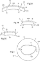
- FIGS. 1A, 1B, 1C ; 2A, 2B, 2C there is shown an ophthalmic lens 10; Having a substrate 11; 21 covered with a film 12; 22 of coating.
- This ophthalmic lens 10; 20 may be a convergent, divergent and / or toric correction lens or a non-corrective lens whose optically useful faces are parallel.
- the substrate 11; 21 is made of a first material, for example mineral glass or organic glass, that is to say polymer.
- the initial portion 13A; 23A of the lens is circular ( Figure 1A , 2A and 3 ).
- the lens 10; 20 must be cut out according to the shape of the corresponding circle of the spectacle frame 10; 20, so that it can be nested in the latter.
- E By desired contour is meant E; F the intersection of the edge of the lens 10; 20 intended to be inserted in the circle of the chosen frame and the useful face on which the film 12; 22 is fixed,
- the lens is more precisely cut out to present on its final slice 13C; 23C a nesting rib 14; 24 (or bevel).
- the interlocking rib 14; 24 here has a V-shaped section, with a peak edge running along the final slice 13C; 23C of the lens 10; 20, and, on either side of this peak edge, two front and rear flanks.
- the wafer of the ophthalmic lens could be cut off so as to have a different profile shape, for example in a slot in an arc.
- the film 12; 22 of coating is made in a second material distinct from that of said substrate 11; 21.
- This second material is for example a transparent plastic material.
- This transparent plastic material is for example a polymeric material having physicochemical or optical bi-refractive, polarization, absorption properties in certain wavelength ranges such as ultraviolet or certain visible wavelengths, such as to give a particular color to the lenses, or reflection or hydrophobicity.
- the film 12; 22 may also comprise one or more layers of coating having, for example, anti-shock, anti-scratch, antireflection or anti-fouling properties.
- the film 12; 22 is fixed on one of the main faces of the substrate 11; 21 which is the main face before 15; 25 of this substrate 11; 21, for example by gluing.
- the lens 10 is bent; 20 complete namely the substrate 11; 21 with the film 12; 22 fixed on its front face 15; 25.
- This process comprises several distinct cutting steps.
- a first step a the lens 10 is cut;
- a first tool 30; 40 Figures 1A and 2A ) at least the thickness of the film 12; 22 of coating fixed on said substrate 11; 21, according to an intermediate contour called in the following reduced outline C; D represented dotted on the Figures 1A and 2A and in full line on the figure 3 .
- This contour reduces C; D is closed and determined according to the desired contour E; Final F of the lens 10; 20 so as to be included in this desired contour.
- the contour reduces C; D therefore has dimensions smaller than those of the desired contour E; F of the lens. In this sense, it can be said that the contour reduces C; D is reduced relative to the desired contour.
- This contour reduces C; D is also, by definition, reduced with respect to the initial contour of the lens before trimming, which corresponds to the contour of the initial slice 13A; 23A of the lens 10; 20.
- This contour reduces C; D internally delimits a central portion 12A; 22A useful from film 12; 22 and externally a peripheral portion 12B; 22B.
- the cutout saves said central portion 12A; 22A of the coating film 12; 22 which is located inside the reduced contour 12A; 22A.
- a second step b the substrate 11 is machined; 21 of the lens 10; By means of a second tool 31; 41, distinct from the first tool 30; 40, without machining the central portion 12A; 22A useful from film 12; 22 of coating, as shown in dotted line on Figures 1B , 2B and 3 .
- the lens 10 is cut on the thickness of the coating film 12 and on a part of the thickness of the substrate 11 of this lens.
- This portion of the substrate thickness is preferably small relative to the total thickness of the lens substrate. It corresponds for example to a thickness less than or equal to 30 percent of the total thickness of the substrate.
- the first tool 30 used to perform this step and shown schematically by an arrow 30 on the Figure 1A is, for example, a two-size milling cutter or a bit, both of small diameter. This small diameter is preferably less than 5 millimeters.
- the first tool 30 may also be a cutting tip.
- the diameter of the tool refers to the diameter of the cutting surface of the tool generated by a cutting generator or a cutting surface of the tool during its rotation about an axis of rotation of the tool.
- the initial slice 13A of the lens 10 is not modified by this step a).
- This machining device 200 is controlled by an electronic and computer device 100.
- the electronic and computer device 100 comprises means for acquiring and displaying data 101 typically comprising a keyboard 101 and a screen 102 adapted to the display of data. a graphical interface, control means able to control the various degrees of freedom of the machining device 200 and an operating system associated with a software application adapted to control these different components.
- the flip-flop 204 is equipped with a lens support formed for example by two shafts 211, 212 for clamping and rotating the lens 10 around a blocking pin A2.
- Each of the shafts 211, 212 has a free end which faces the other and is equipped with a locking nose 213, 214 of the ophthalmic lens 10.
- a first 212 of the two shafts is fixed in translation along the blocking axis A2.
- the second 211 of the two shafts is conversely movable in translation along the blocking axis A2 to effect the compression in axial compression of the ophthalmic lens 10 between the two locking noses 213, 214.
- the two shafts 211, 212 are rotated synchronously by a motor (not shown), via a common drive mechanism (not shown) embedded on the rocker 204.
- This common synchronous rotation drive mechanism is of type current, known in itself.
- the ROT rotation of the shafts 211, 212 is controlled by the electronic and computer device 100.
- the machining device 200 comprises, on the other hand, a set of wheels for edging and trimming the lens.
- This set of grinding wheels comprises the grinding and chamfering grinding wheel 220, which is set in rotation on the grinding wheel axis A3 parallel to the locking pin A2 and which is also driven in rotation by a specific motor.
- This grinding wheel 220 of beveling and cutting has a peripheral portion which is generally cylindrical around the axis of grinding wheels A3 and which carries two grooves V-profile beveling.
- the set of grinding wheels is attached to a common shaft extending along the axis of grinding wheels A3 ensuring its rotational drive during the operation of trimming and bevelling of the ophthalmic lens 10.
- This common shaft which is not visible in the figures, is controlled in rotation by an electric motor driven by the electronic and computer device 100.
- the wheel set is also axially movable in translation along the axis of wheels A3 and is controlled in this translation by a drive motor.
- a drive motor In this case, the entire wheel train, its shaft and its motor is carried by a carriage 225 which is itself mounted on slides 226 secured to the frame 203 to slide along the blocking axis A2.
- the axial mobility movement of the carriage 225 is called "transfer” and is noted TRA on the figure 4 . This transfer is controlled by the electronic and computer device 100.
- the pivoting capacity of the rocker 204 is used around the rocker axis A1.
- This pivoting causes indeed a displacement, here substantially vertical, the ophthalmic lens 10 sandwiched between the shafts 211, 212 which brings the lens closer to or away from the grinding wheel 220 along a restitution axis A4.
- This mobility which makes it possible to restore the shape of beveling desired and programmed in the electronic and computer device 100, is called restitution and is noted RES on the figure 4 .
- the machining device 200 illustrated by the figure 1 further comprises a machining arm 230 provided with the finisher 235 which carries additional machining tools for trimming and finishing the ophthalmic lens 10, and a pedestal which connects the finisher 235 to the frame 203 of the machining device 200.
- the machining arm 230 has a degree of mobility in a direction substantially transverse to the blocking axis A2 and to the axis of the restitution A4. This degree of transverse mobility is called retraction and is noted ESC.
- the retraction consists of a pivoting of the machining arm 230 around the axis of wheels A3.
- the finishing module 235 has, thanks to the transfer mobilities TRA and retraction ESC of the machining arm 230, an adjustable position allowing the additional machining tools to be brought closer to or away from the lens blocked by the shafts 211, 212.
- the electronic and computer device 100 controls the relative movements of the flip-flop 204, the lens 10 and the finisher 235 so that the first tool 30 cuts the film 12 according to the reduced outline C.
- This reduced contour C is determined for example by the electronic and computer device 100 according to the characteristics of the frame chosen by the wearer and the morphological characteristics of this wearer.
- the reduced contour C is also determined according to the cutting characteristics of the first tool used to perform step a), so that the desired contour E for the lens 10 is at the groove 27 formed around this contour reduced C in the lens.
- step a the lens is cut only on the thickness of the coating film.
- the substrate of the lens is then not cut during this step.
- step b) the substrate 11 of the lens 10, according to the desired contour E of the lens, as shown in FIG. Figure 1B .
- the desired contour E corresponds to the contour of the circle of the frame in which the lens is intended to be mounted.
- the second tool 31, used by the operator to perform this step b) and schematically represented on the Figure 1B by an arrow 31, is for example the wheel 220 of clipping and bevelling of the figure 4 .
- the grinding wheel 220 here has a large diameter, that is to say a diameter close to or greater than that of the lens.
- a wheel of medium diameter could be used, for example a few centimeters.
- the desired contour E of the lens is slightly wider than the reduced contour C of the film 12 of coating, the central portion 12A of the film 12 which is bonded to the substrate 11 is not affected by this machining. This avoids any delamination of this central portion 12A of the film 12.
- the reduced contour C of the coating film 12 preferably marries the desired contour E, as shown in Figures 1C and 3 .
- the reduced contour C of the film 12 is preferably calculated so that the difference L1 ( Figures 1C and 3 ) between this reduced contour C of the film 12 and the edge of the cut edge 13C of the lens 10 is less than or equal to at most one millimeter ( figure 1C ) over at least 80 percent of the circumference of the lens 10 once cut away, preferably over its entire circumference.
- the operator also carries out the finishing operations of the lens, for example the beveling, grooving and chamfering operations of the substrate 11 of the lens 10.
- step c) the operator carries on the final edge 13C of the lens 10 the nesting rib 14.
- the peripheral portion 21 B of the coating film 12 is automatically eliminated at the end of the two steps a) and b), as shown in FIG. figure 1C .
- the two cutting steps are each carried out along a generatrix or a cutting plane P1, P2 substantially parallel to the blocking axis A2 of the lens 10, that is to say perpendicular to the average plane of the lens.
- the generatrix or the cutting plane of each step is inclined with respect to the axis A2.
- the generatrix or the cutting surface in which the first tool cuts the coating film can be inclined at an angle of between 10 and 60 degrees with respect to the locking pin A2, so that the diameter of the the central portion of the cut film increases from the outer face of the film towards the face of the film bonded to the ophthalmic lens.
- Steps a) and b) are then performed as previously described.
- the reduced contour of the film is then called the edge of the central part of the film in contact with the substrate.
- step b) it is also conceivable to perform step b) before step a).
- a substrate thickness less than or equal to the total thickness of the substrate.
- the film and the part of the substrate which has not been cut in step b) are then cut out so that the two cuts meet.
- the reduced contour of the film can thus be at the right contour of the desired cutting of the lens: there is no gap between the edge of the wafer of the substrate and the contour of the film, which improves the appearance aesthetic of the front of the lens.
- the operator mills the entire thickness of the coating film 22 and the substrate 21 of the lens 20 as represented by dotted lines on the Figure 2A .
- step a) the operator obliquely cuts the film 22 of coating and the substrate 21, so that the lens 20 has a diameter that widens from the front of the lens 20 carrying the film 22 to the other side of the lens 20 after this step a) cutting.
- This oblique cutting is performed in such a way as to cut the film 22 according to its reduced outline D.
- the reduced contour D of the film 22 is called the edge of the central portion 22A of the film 22 in contact with the substrate 21.
- the lens 20 is machined so that the wafer 23B of the lens 20 after this first step a) forms an angle of between 30 and 60 degrees with the mean plane of the lens 20.
- the first tool 40 used to perform this step a) and schematically represented on the Figure 2A by an arrow, is as in the first embodiment, a two-size milling cutter, a drill of small diameter, or a cutting tip, which does not damage the film 22 during cutting.
- the lens 20 is placed in a grinding device similar to that described in the first embodiment and shown in FIG. figure 4 .
- the first tool 40 is worn in the same way by the finishing module of this grinding device.
- the peripheral portion 22B of the coating film 22 is automatically eliminated at the end of step a), as shown in FIG. Figure 2B .
- the geometry of the wafer 23B of the lens 20 after step a) is determined by the electronic and computer device of the grinding device, as a function of the reduced contour D desired for the film 22, of the shape of the frame selected by the carrier and the morphological characteristics of this carrier.
- the operator then works in a step b) at least a portion of the substrate 21 of the lens 20, according to the desired contour F of the lens, as shown in FIG. Figure 2B .
- the desired contour F corresponds to the contour of the frame of the frame in which the lens is to be mounted.
- Step b) is performed using the second tool 41 shown schematically by an arrow 41 on the Figure 2B .
- This second tool 41 is for example a wheel similar to the grinding wheel 220 of clipping and beveling represented on the figure 4 .
- step b) the cut is straight and the generator or the cutting surface of the second tool used is parallel to the locking axis of the lens.
- the desired contour F extends away from the reduced contour D of the film 22.
- the central portion 22A of the film 22 is not machined during step b). This avoids delamination of this central portion of the film 22.
- the reduced contour D of the coating film 12 preferably matches the desired contour F of the cut-out lens, shown in FIG. Figure 2C .
- the gap L2 between the reduced contour D of the film 22 and the edge of the final wafer 23C of the cut-out lens 20 is less than or equal to one millimeter ( Figure 2C ) over at least 80 percent of the circumference of the cut-away lens, and preferably over its entire circumference. The aesthetic appearance of the lens is thus improved.
- the electronic and computer device of the grinding device also determines the geometry of the final slice 23C of the lens. It controls the relative movements of the rocker, the finisher and the lens to perform both steps a) and b).
- a step c) which can be performed in part simultaneously with step b)
- the operator advantageously performs the finishing operations of the lens 20.
- a rib nesting 24 is made along the cut-out portion 23C of the lens 20.
- a chamfer 28 connecting the final wafer 23C and the front face of the film 22 is formed by obliquely cutting the film 22 and the substrate 21 when of step a). The finish of the lens 20 is thus fast and neat.
- step b) it is conceivable alternatively to perform step b) before step a). Only a portion of the thickness of the substrate of the lens is then machined, so as not to damage the film 22. Then, the operator performs oblique cutting of the film and at least the portion of the substrate thickness which has not been machined previously.
- step a) and step b allow in particular to consider the achievement of these two steps, at least partially, simultaneously. It suffices to order the tools so that they traverse the circumference of the lens successively, one of the two tools having a slight delay relative to the other for the work of a given ray of the lens.
- the film may be attached to the back side of the substrate.
- the process is not modified.
- the rear face of the lens then plays the role of the front face of the lens described above.
- step a it is conceivable for the operator to deposit glue along the circumference of the central portion 12A of the film 12 of coating, corresponding to said reduced contour C, in order to prevent any subsequent detachment of this film after the production of the film. step a).
- a groove formed in the lens substrate is formed along the circumference of the central portion of the coating film and the glue then enters the groove thus dug.
Landscapes
- Engineering & Computer Science (AREA)
- Mechanical Engineering (AREA)
- Chemical & Material Sciences (AREA)
- Ceramic Engineering (AREA)
- Inorganic Chemistry (AREA)
- Physics & Mathematics (AREA)
- Health & Medical Sciences (AREA)
- Ophthalmology & Optometry (AREA)
- General Health & Medical Sciences (AREA)
- General Physics & Mathematics (AREA)
- Optics & Photonics (AREA)
- Eyeglasses (AREA)
- Grinding And Polishing Of Tertiary Curved Surfaces And Surfaces With Complex Shapes (AREA)
Description
- La présente invention concerne de manière générale le détourage des lentilles ophtalmiques, et plus particulièrement un procédé de détourage d'une lentille ophtalmique revêtue d'un film.
- Un procédé de détourage d'une lentille ophtalmique est par exemple connu du document
WO 2007/128903 . - Certaines lentilles ophtalmiques sont munies sur l'une de leurs faces d'une couche de revêtement se présentant sous la forme d'un film rapporté sur le substrat de la lentille, par exemple collé sur ce substrat.
- Ces films assurent un meilleur confort pour le porteur et de meilleures performances de la lentille.
- L'obtention d'une telle lentille ophtalmique munie d'un film de revêtement et prête à être montée dans la monture choisie par le porteur, c'est-à-dire détourée selon le contour adapté au montage des lentilles sur cette monture, nécessite actuellement la réalisation de nombreuses étapes délicates à mettre en oeuvre.
- En effet, il n'est pas possible de détourer de manière classique, à l'aide d'une meule, la lentille munie de son film. Celui-ci est fragile et subirait lors d'un tel détourage des décollements et/ou des délaminages, c'est-à-dire une séparation des différentes strates du film, inacceptables.
- Afin de remédier aux inconvénients précités de l'état de la technique, la présente invention propose un procédé de détourage d'une lentille ophtalmique de lunettes tel que décrit dans la revendication 1.
- Ce procédé autorise le détourage direct de la lentille munie de son film de revêtement. Ce film de revêtement peut être monocouche ou multicouche et présenter une structure continue ou microstructurée. Il est fixé de manière temporaire ou permanente sur la face correspondante de la lentille. Cette face de la lentille peut en outre présenter d'autres traitements de surface sous la forme de couches de revêtement.
- En effet, l'étape a) est réalisée à l'aide d'un outil de découpe différent de l'outil de taillage du type meule ou fraise utilisé à l'étape b), choisi pour ne pas provoquer l'apparition de défauts de cohésion entre le film et le substrat ou entre différentes parties du film, en particulier, des décollements et/ou des délaminages du film de revêtement.
- En outre, lors de l'étape a), la lentille est découpée sur au moins l'épaisseur du film selon un contour réduit fermé calculé en fonction du contour souhaité pour la lentille de manière à ce que ce contour réduit soit inclus dans le contour souhaité, à une distance déterminée de ce contour souhaité supérieure à une valeur seuil.
- Lors de l'étape b), le contour souhaité selon lequel la lentille est usinée est ainsi plus large que le contour réduit selon lequel le film de revêtement est découpé dans l'étape a). De cette façon, la partie centrale utile du film de revêtement n'est pas découpée lors de cette étape b), ce qui évite un décollement ou un délaminage du film.
- Ce procédé de détourage limite les manipulations du film de revêtement et du substrat, ce qui est simple et rapide pour l'opérateur.
- En outre, le positionnement du film de revêtement par rapport au substrat de la lentille est précis et le rendu esthétique de la lentille obtenue est ainsi satisfaisant. La grande précision du positionnement du film est particulièrement avantageuse dans le cas de films qui présentent des propriétés non uniformes (variant dans l'espace) et qui doivent donc être très précisément positionnés sur la lentille. C'est le cas par exemple de films de revêtement à variation d'indice optique.
- La tenue et la finition du film de revêtement sur la base de la lentille est ainsi amélioré.
- Selon une autre caractéristique avantageuse et non limitative du procédé selon l'invention, lors de l'étape c), on procède à des opérations de biseautage et/ou de rainurage et/ou de chanfreinage du substrat de la lentille.
- La préparation de la lentille pour son montage dans la monture de lunettes choisie par le porteur est ainsi rapide et aisée.
- Il est possible, sans sortir du cadre de l'invention, de réaliser l'étape b) après l'étape a) ou, inversement, l'étape a) après l'étape b), ou encore de réaliser au moins une partie des étapes a) et b) simultanément.
- D'autres caractéristiques avantageuses et non limitatives du procédé selon l'invention sont décrites dans les revendications 5 à 12.
- La description qui va suivre, en regard des dessins annexés, donnée à titre d'exemple non limitatif, fera bien comprendre en quoi consiste l'invention et comment elle peut être réalisée.
- Sur les dessins annexés :
- les
figures 1A, 1B et 1C montrent des vues schématiques en coupe de la lentille ophtalmique au cours de différentes étapes successives de son détourage selon un premier mode de réalisation du procédé conforme à l'invention, - les
figures 2A, 2B et 2C montrent des vues schématiques en coupe de la lentille ophtalmique au cours de différentes étapes successives de son détourage selon un deuxième mode de réalisation du procédé conforme à l'invention, - la
figure 3 est une vue schématique de dessus de la lentille représentée sur lafigure 1B , - la
figure 4 est une vue schématique en perspective d'un dispositif de meulage utilisé pour mettre en oeuvre le procédé selon l'invention. - Dans la description qui suit, les références numériques désignant des éléments relatifs à un même mode de réalisation sont séparées par des virgules, tandis que les références numériques désignant des éléments relatifs aux différents modes de réalisations sont séparées par des point-virgules.
- Sur les
figures 1A, 1B, 1C ;2A, 2B, 2C , on a représenté une lentille ophtalmique 10; 20 comportant un substrat 11; 21 recouvert d'un film 12; 22 de revêtement. Cette lentille ophtalmique 10; 20 peut être une lentille correctrice convergente, divergente et/ou torique ou une lentille non correctrice dont les faces optiquement utiles sont parallèles. - Le substrat 11; 21 est réalisé dans un premier matériau, par exemple en verre minéral ou en verre organique, c'est-à-dire en polymère.
- Il présente deux faces principales 15, 16; 25, 26 correspondant aux deux faces principales de la lentille ophtalmique 10; 20.
- Avant détourage selon le contour souhaité E; F de la lentille, qui correspond à la monture choisie par le porteur et sur laquelle la lentille 10; 20 est destinée à être montée, la tranche initiale 13A; 23A de la lentille est circulaire (
figure 1A ,2A et 3 ). La lentille 10; 20 doit être détourée selon la forme du cercle correspondant de la monture de lunettes 10; 20, de manière à pouvoir être emboîtée dans ce dernier. - On entend par contour souhaité E; F l'intersection de la tranche de la lentille 10; 20 destinée à être insérée dans le cercle de la monture choisie et de la face utile sur laquelle le film 12; 22 est fixé,
- Comme le montrent les
figures 1C et2C , la lentille est plus précisément détourée pour présenter sur sa tranche finale 13C; 23C une nervure d'emboîtement 14; 24 (ou biseau). La nervure d'emboîtement 14; 24 présente ici une section en forme de V, avec une arête de sommet qui court le long de la tranche finale 13C; 23C de la lentille 10; 20, et, de part et d'autre de cette arête de sommet, deux flancs avant et arrière. - En variante, la tranche de la lentille ophtalmique pourrait être détourée de manière à présenter un profil de forme différente, par exemple en créneau au en arc de cercle.
- Le film 12; 22 de revêtement est réalisé dans un deuxième matériau distinct de celui dudit substrat 11; 21.
- Ce deuxième matériau est par exemple un matériau plastique transparent. Ce matériau plastique transparent est par exemple un matériau polymère présentant des propriétés physico-chimique ou optique de bifréfringence, de polarisation, d'absorption dans certaines plages de longueur d'onde comme les ultra-violets ou certaines longueurs d'onde visible, de manière à donner une teinte particulière aux lentilles, ou encore de réflexion ou d'hydrophobie.
- Le film 12; 22 peut également comporter une ou plusieurs couches de revêtement présentant par exemple, des propriétés anti-choc, anti-rayures, antireflet ou anti-salissures.
- Le film 12; 22 est fixé sur l'une des faces principales du substrat 11; 21 qui est la face principale avant 15; 25 de ce substrat 11; 21, par exemple par collage.
- De manière remarquable, grâce au procédé de détourage selon l'invention, on détoure la lentille 10; 20 complète à savoir le substrat 11; 21 avec le film 12; 22 fixé sur sa face avant 15; 25.
- Ce procédé comporte plusieurs étapes de découpe distinctes.
- Dans une première étape a), on découpe la lentille 10; 20 au moyen d'un premier outil 30; 40 (
figures 1A et2A ) sur au moins l'épaisseur du film 12; 22 de revêtement fixé sur ledit substrat 11; 21, selon un contour intermédiaire appelé dans la suite contour réduit C; D représenté en pointillé sur lesfigures 1A et2A et en trait plein sur lafigure 3 . - Ce contour réduit C; D est fermé et déterminé en fonction du contour souhaité E; F final de la lentille 10; 20 de manière à être inclus dans ce contour souhaité. Le contour réduit C; D présente donc des dimensions plus petites que celles du contour souhaité E; F de la lentille. En ce sens, on peut dire que le contour réduit C; D est réduit par rapport au contour souhaité. Ce contour réduit C; D est également, par définition, réduit par rapport au contour initial de la lentille avant détourage, qui correspond au contour de la tranche initiale 13A; 23A de la lentille 10; 20.
- Ce contour réduit C; D délimite intérieurement une partie centrale 12A; 22A utile du film 12; 22 de revêtement et extérieurement une partie périphérique 12B; 22B. En d'autres termes, lors de l'étape a), la découpe épargne ladite partie centrale 12A; 22A du film de revêtement 12; 22 qui est située à l'intérieur du contour réduit 12A; 22A.
- Dans une deuxième étape b), on taille par usinage le substrat 11; 21 de la lentille 10; 20 au moyen d'un second outil 31; 41, distinct du premier outil 30; 40, sans usiner la partie centrale 12A; 22A utile du film 12; 22 de revêtement, comme représenté en pointillé sur les
figures 1B ,2B et 3 . - Selon un premier mode de réalisation de l'invention représenté sur les
figures 1A, 1B, 1C et3 , dans la première étape a), on découpe la lentille 10 sur l'épaisseur du film 12 de revêtement et sur une partie de l'épaisseur du substrat 11 de cette lentille. - Un sillon 27, creusé dans le film de revêtement et une partie de l'épaisseur du substrat de la lentille, est ainsi formé le long de la circonférence de la partie centrale du film de revêtement.
- Cette partie de l'épaisseur du substrat est de préférence faible par rapport à l'épaisseur totale du substrat de la lentille. Elle correspond par exemple à une épaisseur inférieure ou égale à 30 pour cent de l'épaisseur totale du substrat.
- Elle correspond de préférence à une épaisseur inférieure ou égale à un millimètre.
- Le premier outil 30 utilisé pour réaliser cette étape et représenté schématiquement par une flèche 30 sur la
figure 1A , est par exemple une fraise deux tailles ou un foret, l'un comme l'autre de petit diamètre. Ce petit diamètre est de préférence inférieur à 5 millimètres. Le premier outil 30 peut également être une pointe coupante. - On entend ici par diamètre de l'outil le diamètre de la surface de coupe de l'outil générée par une génératrice coupante ou une surface coupante de l'outil lors de sa rotation autour d'un axe de rotation de l'outil.
- Ces outils présentent l'avantage de ne pas endommager le film 12 de revêtement. En particulier, ils ne provoquent pas de délaminage de ce film.
- La tranche initiale 13A de la lentille 10 n'est pas modifiée par cette étape a).
- En pratique, l'opérateur place par exemple la lentille 10 dans un dispositif d'usinage 200 connu en lui-même, tel que celui décrit dans le document
WO2008/043910 . Un tel dispositif, tel qu'illustré sur lafigure 4 comporte par exemple : - une bascule 204 qui est montée pivotante autour d'un axe de référence A1, en pratique un axe horizontal, sur un châssis 203, et qui comporte des moyens de support de la lentille 10 permettant une mise en rotation motorisée de la lentille 10 autour d'un axe de blocage A2 sensiblement perpendiculaire au plan moyen de la lentille et parallèle à l'axe A1 ;
- au moins une meule 220, qui est calée en rotation sur un axe de meule A3 parallèle à l'axe de référence A1, et qui est elle aussi entraînée en rotation par un moteur ;
- un module de finition 235 qui est monté à rotation autour de l'axe de meule A3, et qui embarque ledit premier outil 30; 40 et éventuellement des moyens de perçage de la lentille ophtalmique 10.
- Ce dispositif d'usinage 200 est piloté par un dispositif électronique et informatique 100. Le dispositif électronique et informatique 100 comprend des moyens d'acquisition et d'affichage de données 101 comportant typiquement un clavier 101 et un écran 102 adapté à l'affichage d'une interface graphique, des moyens de pilotage aptes à piloter les différents degrés de liberté du dispositif d'usinage 200 et un système d'exploitation associé à un applicatif logiciel adaptés à piloter ces différentes composants.
- La bascule 204 est équipée d'un support de lentille formé par exemple par deux arbres 211, 212 de serrage et d'entraînement en rotation de la lentille 10 autour de un axe de blocage A2.
- Ces deux arbres sont alignés l'un avec l'autre suivant l'axe de blocage A2 parallèle à l'axe de référence A1. Chacun des arbres 211, 212 possède une extrémité libre qui fait face à l'autre et qui est équipée d'un nez de blocage 213, 214 de la lentille ophtalmique 10.
- Un premier 212 des deux arbres est fixe en translation suivant l'axe de blocage A2. Le second 211 des deux arbres est au contraire mobile en translation suivant l'axe de blocage A2 pour réaliser le serrage en compression axiale de la lentille ophtalmique 10 entre les deux nez de blocage 213, 214.
- Les deux arbres 211, 212 sont entraînés en rotation de façon synchrone par un moteur (non représenté), via un mécanisme d'entraînement commun (non représenté) embarqué sur la bascule 204. Ce mécanisme commun d'entraînement synchrone en rotation est de type courant, connu en lui-même.
- La rotation ROT des arbres 211, 212 est pilotée par le dispositif électronique et informatique 100.
- Le dispositif d'usinage 200 comporte, d'autre part, un train de meules pour le débordage et le détourage de la lentille. Ce train de meules comprend la meule 220 de détourage et de biseautage, qui est calée en rotation sur l'axe de meules A3 parallèle à l'axe de blocage A2 et qui est elle aussi entraînée en rotation par un moteur spécifique. Cette meule 220 de détourage et de biseautage présente une tranche périphérique qui est globalement cylindrique autour de l'axe de meules A3 et qui porte deux gorges de biseautage de profils en V.
- Le train de meules est rapporté sur un arbre commun s'étendant selon l'axe de meules A3 assurant son entraînement en rotation lors de l'opération de détourage et de biseautage de la lentille ophtalmique 10. Cet arbre commun, qui n'est pas visible sur les figures, est commandé en rotation par un moteur électrique piloté par le dispositif électronique et informatique 100.
- Le train de meules est en outre mobile axialement en translation suivant l'axe de meules A3 et est commandé dans cette translation par une motorisation pilotée. En l'espèce, l'ensemble du train de meules, de son arbre et de son moteur est porté par un chariot 225 qui est lui-même monté sur des glissières 226 solidaires du châssis 203 pour coulisser suivant l'axe de blocage A2. Le mouvement de mobilité axiale du chariot 225 est appelé « transfert » et est noté TRA sur la
figure 4 . Ce transfert est piloté par le dispositif électronique et informatique 100. - Pour permettre un réglage dynamique de l'entraxe entre l'axe de meules A3 de la meule 220 de détourage et de biseautage et l'axe de blocage A2, on utilise la capacité de pivotement de la bascule 204 autour de l'axe de bascule A1.
- Ce pivotement provoque en effet un déplacement, ici sensiblement vertical, de la lentille ophtalmique 10 enserrée entre les arbres 211, 212 qui rapproche ou éloigne la lentille de la meule 220 selon un axe de restitution A4. Cette mobilité, qui permet de restituer la forme de biseautage voulue et programmée dans le dispositif électronique et informatique 100, est appelée restitution et est notée RES sur la
figure 4 . - Le dispositif d'usinage 200 illustré par la
figure 1 comporte de plus un bras d'usinage 230 pourvu du module de finition 235 qui porte des outils d'usinage supplémentaires pour le détourage et la finition de la lentille ophtalmique 10, et d'un socle qui raccorde le module de finition 235 au châssis 203 du dispositif d'usinage 200. - Le bras d'usinage 230 présente un degré de mobilité suivant une direction sensiblement transversale à l'axe de blocage A2 et à l'axe de la restitution A4. Ce degré de mobilité transversale est appelé escamotage et est noté ESC. En l'espèce, l'escamotage consiste en un pivotement du bras d'usinage 230 autour de l'axe de meules A3.
- Le module de finition 235 présente, grâce aux mobilités de transfert TRA et d'escamotage ESC du bras d'usinage 230, une position réglable permettant aux outils d'usinage supplémentaires de pouvoir être rapprochés ou éloignés de la lentille bloquée par les arbres 211, 212.
- En service, le dispositif électronique et informatique 100 pilote les mouvements relatifs de la bascule 204, de la lentille 10 et du module de finition 235 pour que le premier outil 30 découpe le film 12 selon le contour réduit C.
- Ce contour réduit C est déterminé par exemple par le dispositif électronique et informatique 100 en fonction des caractéristiques de la monture choisie par le porteur et des caractéristiques morphologiques de ce porteur.
- Le contour réduit C est également déterminé en fonction des caractéristiques de coupe du premier outil utilisé pour réaliser l'étape a), de telle sorte que le contour souhaité E pour la lentille 10 se situe au niveau du sillon 27 formé tout autour de ce contour réduit C dans la lentille.
- Selon une variante, lors de l'étape a), la lentille est découpée uniquement sur l'épaisseur du film de revêtement. Le substrat de la lentille n'est alors pas découpé lors de cette étape.
- L'opérateur usine ensuite dans l'étape b) le substrat 11 de la lentille 10, selon le contour souhaité E de la lentille, comme représenté sur la
figure 1B . Comme précisé précédemment, le contour souhaité E correspond au contour du cercle de la monture dans laquelle la lentille est destinée à être montée. - Le deuxième outil 31, utilisé par l'opérateur pour réaliser cette étape b) et représenté schématiquement sur la
figure 1B par une flèche 31, est par exemple la meule 220 de détourage et de biseautage de lafigure 4 . La meule 220 présente ici un grand diamètre, c'est-à-dire un diamètre voisin de ou supérieur à celui de la lentille. On pourrait toutefois utiliser une meule de moyen diamètre, par exemple de quelques centimètres. En variante, on peut aussi utiliser une fraise une taille de grand ou moyen diamètre. - Le contour souhaité E de la lentille est légèrement plus large que le contour réduit C du film 12 de revêtement, la partie centrale 12A du film 12 qui est collée sur le substrat 11 n'est pas affecté par cet usinage. On évite ainsi tout délaminage de cette partie centrale 12A du film 12.
- Le contour réduit C du film 12 de revêtement épouse de préférence le contour souhaité E, comme représenté sur les
figures 1C et3 . Le contour réduit C du film 12 est de préférence calculé pour que l'écart L1 (figures 1C et3 ) entre ce contour réduit C du film 12 et le bord de la tranche détourée 13C de la lentille 10 soit inférieur ou égal au maximum à un millimètre (figure 1C ) sur au moins 80 pour cent de la circonférence de la lentille 10 une fois détourée, de préférence sur toute sa circonférence. - Lors d'une étape c), l'opérateur procède en outre aux opérations de finitions de la lentille, par exemple aux opérations de biseautage, de rainurage et de chanfreinage du substrat 11 de la lentille 10.
- Par exemple, lors de l'étape c), réalisée ici simultanément avec l'étape b), l'opérateur réalise sur la tranche finale 13C de la lentille 10 la nervure d'emboitement 14.
- La partie périphérique 21 B du film 12 de revêtement est automatiquement éliminée à l'issue des deux étapes a) et b), comme représenté sur la
figure 1C . - Dans le premier mode de réalisation décrit, les deux étapes de découpe sont chacune réalisées selon une génératrice ou un plan de coupe P1, P2 sensiblement parallèle à l'axe de blocage A2 de la lentille 10, c'est-à-dire perpendiculaire au plan moyen de la lentille.
- En variante, on peut envisager que la génératrice ou le plan de coupe de chaque étape soit incliné par rapport à l'axe A2.
- Pour cela, on peut envisager d'utiliser un outil dont l'axe de rotation est parallèle à l'axe de blocage de la lentille et dont la génératrice ou la surface coupante est incliné par rapport à cet axe de rotation, ou alors d'utiliser un outil dont la génératrice ou la surface coupante est parallèle par rapport à cet axe de rotation et dont l'axe de rotation est incliné par rapport à l'axe de blocage de la lentille.
- Par exemple, la génératrice ou la surface coupante selon laquelle le premier outil découpe le film de revêtement peut être inclinée d'un angle compris entre 10 et 60 degrés par rapport à l'axe de blocage A2, de manière à ce que le diamètre de la partie centrale du film découpé augmente depuis la face externe du film vers la face du film collée sur la lentille ophtalmique.
- Les étapes a) et b) sont alors réalisées de la manière décrite précédemment. On appelle alors le contour réduit du film le bord de la partie centrale du film en contact avec le substrat.
- On peut également envisager de réaliser l'étape b) avant l'étape a). On usine alors lors de l'étape b) une épaisseur de substrat inférieure ou égale à l'épaisseur totale du substrat. On découpe ensuite le film et la partie du substrat qui n'a pas été découpée dans l'étape b) de manière à ce que les deux découpes se rejoignent. Le contour réduit du film peut ainsi se trouver au droit du contour souhaité de découpe de la lentille : il n'y a pas alors d'écart entre le bord de la tranche du substrat et le contour du film, ce qui améliore l'aspect esthétique de la face avant de la lentille.
- Selon un deuxième mode de réalisation du procédé selon l'invention, représenté sur les
figures 2A à 2C , lors de l'étape a), l'opérateur usine toute l'épaisseur du film 22 de revêtement et du substrat 21 de la lentille 20 comme représenté par des pointillés sur lafigure 2A . - Plus précisément, lors de l'étape a), l'opérateur réalise un découpage oblique du film 22 de revêtement et du substrat 21, de manière à ce que la lentille 20 présente un diamètre qui s'élargit depuis la face avant de la lentille 20 portant le film 22 vers l'autre face de la lentille 20 après cette étape a) de découpage.
- Ce découpage oblique est réalisé de manière à découper le film 22 selon son contour réduit D. On appelle ici le contour réduit D du film 22 le bord de la partie centrale 22A du film 22 en contact avec le substrat 21.
- Pour cela, comme représenté sur la
figure 2B , la lentille 20 est usinée de manière à ce que la tranche 23B de la lentille 20 après cette première étape a) forme un angle compris entre 30 et 60 degrés avec le plan moyen de la lentille 20. - Le premier outil 40 utilisé pour réaliser cette étape a) et représenté schématiquement sur la
figure 2A par une flèche, est comme dans le premier mode de réalisation, une fraise deux tailles, un foret de petit diamètre, ou encore une pointe coupante, qui n'endommage pas le film 22 au cours de la découpe. - On peut, comme exposé dans le premier mode de réalisation, envisager, pour réaliser cette découpe oblique, d'utiliser un outil dont l'axe de rotation est parallèle à l'axe de blocage de la lentille et dont la génératrice ou la surface coupante est incliné par rapport à l'axe de rotation de l'outil, ou alors d'utiliser un outil dont la génératrice ou la surface coupante est parallèle par rapport à cet axe de rotation et dont l'axe de rotation est incliné par rapport à l'axe de blocage de la lentille.
- En pratique, la lentille 20 est placée dans un dispositif de meulage semblable à celui décrit dans le premier mode de réalisation et représenté sur la
figure 4 . Le premier outil 40 est porté de la même façon par le module de finition de ce dispositif de meulage. - La partie périphérique 22B du film 22 de revêtement est automatiquement éliminée à l'issue de l'étape a), comme représenté sur la
figure 2B . - La géométrie de la tranche 23B de la lentille 20 après l'étape a) est déterminée par le dispositif électronique et informatique du dispositif de meulage, en fonction du contour réduit D souhaité pour le film 22, de la forme de la monture choisie par le porteur et les caractéristiques morphologiques de ce porteur.
- L'opérateur usine ensuite dans une étape b) au moins une partie du substrat 21 de la lentille 20, selon le contour souhaité F de la lentille, comme représenté sur la
figure 2B . Comme précisé précédemment, le contour souhaité F correspond au contour du cercle de la monture dans laquelle la lentille est destinée à être montée. - L'étape b) est réalisée à l'aide du deuxième outil 41 représenté schématiquement par une flèche 41 sur la
figure 2B . Ce deuxième outil 41 est par exemple une meule semblable à la meule 220 de détourage et de biseautage représentée sur lafigure 4 . - Dans l'étape b), la découpe est droite et la génératrice ou la surface coupante du deuxième outil utilisé est parallèle par rapport à l'axe de blocage de la lentille.
- Le contour souhaité F s'étend à distance du contour réduit D du film 22. Ainsi, la partie centrale 22A du film 22 n'est pas usinée lors de l'étape b). On évite ainsi tout délaminage de cette partie centrale du film 22.
- Le contour réduit D du film 12 de revêtement épouse de préférence le contour souhaité F de la lentille 20 détourée, représenté sur la
figure 2C . L'écart L2 entre le contour réduit D du film 22 et le bord de la tranche finale 23C de la lentille 20 détourée est inférieur ou égal à un millimètre (figure 2C ) sur au moins 80 pour cent de la circonférence de la lentille 20 détourée, et de préférence sur toute sa circonférence. L'aspect esthétique de la lentille est ainsi amélioré. - Comme dans le premier mode de réalisation, le dispositif électronique et informatique du dispositif de meulage détermine également la géométrie de la tranche finale 23C de la lentille. Il commande les mouvements relatifs de la bascule, du module de finition et de la lentille pour réaliser les deux étapes a) et b).
- Comme dans le premier mode de réalisation, au cours d'une étape c), qui peut être réalisée en partie simultanément avec l'étape b), l'opérateur réalise avantageusement les opérations de finitions de la lentille 20. Ici, une nervure d'emboîtement 24 est réalisée le long de la tranche détourée 23C de la lentille 20. En outre, un chanfrein 28 reliant la tranche finale 23C et la face avant du film 22 est formé par la découpe oblique du film 22 et du substrat 21 lors de l'étape a). La finition de la lentille 20 est ainsi rapide et soignée.
- On peut envisager en variante de réaliser l'étape b) avant l'étape a). Seule une partie de l'épaisseur du substrat de la lentille est alors usinée, de manière à ne pas endommager le film 22. Ensuite, l'opérateur réalise la découpe oblique du film et d'au moins la partie de l'épaisseur du substrat qui n'a pas été usinée précédemment.
- L'utilisation d'outils différents, l'un étant choisi par exemple parmi la fraise deux tailles, le foret, la pointe coupante et l'autre étant par exemple une meule ou une fraise une taille, pour réaliser l'étape a) et l'étape b), permet notamment d'envisager la réalisation de ces deux étapes, au moins partiellement, de façon simultanée. Il suffit pour cela de commander les outils pour qu'ils parcourent la circonférence de la lentille successivement, l'un des deux outils présentant un léger retard par rapport à l'autre pour le travail d'un rayon donné de la lentille.
- En variante, le film peut être fixé sur la face arrière du substrat. Le procédé n'est pas modifié. La face arrière de la lentille joue alors le rôle de la face avant de la lentille décrite précédemment.
- On peut par exemple envisager que l'opérateur dépose de la colle le long de la circonférence de la partie centrale 12A du film 12 de revêtement, correspondant audit contour réduit C, afin d'empêcher tout décollement ultérieur de ce film après la réalisation de l'étape a).
- Dans le cas où une partie de l'épaisseur du substrat de la lentille est découpée en plus du film de revêtement, un sillon creusé dans le substrat de la lentille est formé le long de la circonférence de la partie centrale du film de revêtement et la colle pénètre alors dans le sillon ainsi creusé.
Claims (12)
- Procédé de détourage d'une lentille ophtalmique (10; 20) de lunettes suivant un contour souhaité (E; F), la lentille (10; 20) présentant deux faces principales optiquement utiles et comportant, d'une part, un substrat (11; 21) réalisé dans un premier matériau et présentant deux faces principales (15, 16; 25, 26) correspondant aux deux faces principales de la lentille (10; 20) et, d'autre part, au moins un film de revêtement (12; 22) réalisé dans un matériau distinct de celui dudit substrat (11; 21), ledit film de revêtement (12; 22) étant préalablement fixé sur au moins une des faces principales (15, 16; 25, 26) du substrat (11;21), le procédé comporte les étapes suivantes :a) une étape de découpe par usinage de la lentille (10; 20) au moyen d'un premier outil (30; 40) sur au moins l'épaisseur du film de revêtement (12; 22) préalablement fixé sur le substrat (11; 21), cette découpe délimitant intérieurement une partie centrale (12A; 22A) utile du film de revêtement (12; 22) présentant un contour réduit (C ; D), fermé et calculé en fonction dudit contour souhaité (E; F), et le procédé est caractérisé par les étapes suivantes:b) une étape de taillage par usinage du chant du substrat (11; 21) suivant ledit contour souhaité (E; F), au moyen d'un second outil (31; 41), distinct du premier outil (30; 40), sans usinage de la partie centrale (12A; 22A) utile du film de revêtement (12, 22),c) au moins une étape ultérieure de finition par usinage du chant du substrat (11; 21), sans usinage de la partie centrale (12A; 22A) utile du film de revêtement (12; 22).
- Procédé selon l'une des revendications précédentes, dans lequel, lors de l'étape c), on procède à des opérations de biseautage et/ou de rainurage et/ou de chanfreinage du substrat (11; 21) de la lentille (10; 20).
- Procédé selon l'une des revendications précédentes, dans lequel on réalise les étapes a) et b) de manière séquentielle, l'une après l'autre, dans un ordre quelconque.
- Procédé selon l'une des revendications 1 et 2, dans lequel on réalise au moins une partie des étapes a) et b) simultanément.
- Procédé selon l'une des revendications précédentes, dans lequel on réalise l'étape a) au moyen d'une fraise.
- Procédé selon l'une des revendications précédentes, dans lequel on réalise l'étape a) au moyen d'une pointe coupante.
- Procédé selon l'une des revendications précédentes, dans lequel on réalise l'étape b) au moyen d'une meule.
- Procédé selon l'une des revendications précédentes, dans lequel, lors de l'étape a), on usine ledit substrat (11; 21) de la lentille (10; 20) sur au moins une partie de son épaisseur.
- Procédé selon la revendication précédente, dans lequel, lors de l'étape a), le substrat (11) de la lentille est usiné sur une partie de son épaisseur inférieure ou égale à 30 pour cent de l'épaisseur totale dudit substrat (11).
- Procédé selon l'une des revendications 8 et 9, dans lequel, lors de l'étape a), on réalise un découpage oblique du film (22) de revêtement et d'au moins une partie du substrat (21).
- Procédé selon la revendication 10, dans lequel ledit découpage oblique est réalisé sur l'épaisseur totale du film (22) de revêtement et du substrat (21).
- Procédé selon l'une des revendications précédentes, dans lequel on découpe le film (12; 22) de revêtement et le substrat (11; 21) de la lentille de telle sorte qu'au moins 80 pour cent du contour (C; D) de la partie centrale (12A; 22A) utile du film (12; 22) de revêtement soit distant d'au plus 1 millimètre du bord de la face de la lentille (10; 20) sur laquelle est fixé le film (12; 22) de revêtement.
Applications Claiming Priority (2)
| Application Number | Priority Date | Filing Date | Title |
|---|---|---|---|
| FR1002955A FR2962676B1 (fr) | 2010-07-13 | 2010-07-13 | Procede de detourage d'une lentille ophtalmique de lunettes comportant un film de revetement. |
| PCT/FR2011/000386 WO2012007654A1 (fr) | 2010-07-13 | 2011-07-01 | Procédé de détourage d'une lentille ophtalmique de lunettes comportant un film de revêtement |
Publications (2)
| Publication Number | Publication Date |
|---|---|
| EP2593271A1 EP2593271A1 (fr) | 2013-05-22 |
| EP2593271B1 true EP2593271B1 (fr) | 2017-05-24 |
Family
ID=43629299
Family Applications (1)
| Application Number | Title | Priority Date | Filing Date |
|---|---|---|---|
| EP11744039.6A Active EP2593271B1 (fr) | 2010-07-13 | 2011-07-01 | Procédé de détourage d'une lentille ophtalmique de lunettes comportant un film de revêtement |
Country Status (6)
| Country | Link |
|---|---|
| US (1) | US9446491B2 (fr) |
| EP (1) | EP2593271B1 (fr) |
| KR (1) | KR101752256B1 (fr) |
| CN (1) | CN102985220B (fr) |
| FR (1) | FR2962676B1 (fr) |
| WO (1) | WO2012007654A1 (fr) |
Families Citing this family (9)
| Publication number | Priority date | Publication date | Assignee | Title |
|---|---|---|---|---|
| FR2964336B1 (fr) * | 2010-09-07 | 2012-09-14 | Essilor Int | Procede de detourage d'une lentille ophtalmique |
| FR2990369B1 (fr) | 2012-05-09 | 2014-08-29 | Essilor Int | Procede de detourage d'une lentille ophtalmique multicouche |
| JP6063325B2 (ja) * | 2013-03-28 | 2017-01-18 | Hoya株式会社 | レンズ加工方法、レンズ加工プログラムおよび加工制御装置 |
| KR20170000228U (ko) | 2015-07-08 | 2017-01-18 | 강병우 | 영화 관람용 주변시야 가리개 |
| DE102015009973A1 (de) * | 2015-07-31 | 2017-02-02 | Satisloh Ag | Verfahren zur Bearbeitung von optischen Werkstücken, insbesondere Brillenlinsen aus Kunststoff |
| GB2574033A (en) * | 2018-05-23 | 2019-11-27 | Shamir Optical Ind Ltd | Optical article |
| EP3636423A1 (fr) * | 2018-10-09 | 2020-04-15 | Essilor International (Compagnie Generale D'optique) | Procédé de fabrication d'un élément optique avec un film fonctionnel |
| WO2020187651A1 (fr) * | 2019-03-15 | 2020-09-24 | Essilor International | Procédé pour assister un utilisateur à l'application d'une vignette adhésive sur une face d'une lentille ophtalmique avec un contour initial avant une opération de débordage et dispositif de mise en œuvre du procédé |
| DE102021004831A1 (de) * | 2021-09-24 | 2023-03-30 | Satisloh Ag | Verfahren zur spanenden bearbeitung von optischen werkstücken, insbesondere brillenlinsen aus kunststoff |
Family Cites Families (46)
| Publication number | Priority date | Publication date | Assignee | Title |
|---|---|---|---|---|
| US2231994A (en) * | 1940-05-09 | 1941-02-18 | Arthur M Flattem | Lens cutting machine |
| US2410443A (en) * | 1945-05-25 | 1946-11-05 | Howard G Hoffer | Apparatus for shaping objects provided with curved surfaces |
| US3063340A (en) * | 1958-12-19 | 1962-11-13 | American Optical Corp | Bevel-edged lenses |
| US3030859A (en) * | 1959-05-25 | 1962-04-24 | Jr Daniel O Elliott | Method of making contact lenses |
| US3087285A (en) * | 1960-04-09 | 1963-04-30 | Lissac Georges | Machine for shaping the edges of spectacle glasses |
| US3170374A (en) * | 1962-04-26 | 1965-02-23 | Russell M Malamut | Apparatus for producing lens patterns from spectacle frame lens openings |
| US3313031A (en) * | 1964-11-16 | 1967-04-11 | George L Lowe | Ophthalmic lens former |
| US3905163A (en) * | 1974-03-06 | 1975-09-16 | Tropel | Lens making method |
| US3899314A (en) * | 1974-03-18 | 1975-08-12 | American Optical Corp | Lens manufacturing process |
| JPS6044646B2 (ja) * | 1974-04-10 | 1985-10-04 | 東京光学機械株式会社 | 強化レンズの製造方法 |
| US3894361A (en) * | 1974-09-03 | 1975-07-15 | Dimelp Optical Co Inc | Lens grinding machine |
| US4149344A (en) * | 1976-01-05 | 1979-04-17 | Computer Management Services, Inc. | Single-point blocking method of surfacing and edging spectacle lenses |
| JPH0227116U (fr) * | 1988-04-08 | 1990-02-22 | ||
| FR2689794B1 (fr) * | 1992-04-14 | 1995-02-17 | Wernicke & Co Gmbh | Machine à usiner le bord d'un verre de lunettes. |
| US5512004A (en) * | 1993-06-08 | 1996-04-30 | Coburn Optical Industries, Inc. | Lens edging machine bevel control process |
| US5451281A (en) * | 1994-01-18 | 1995-09-19 | Lipman; Arnold | Process for imparting scratch resistance to ophthalmic lenses during edging |
| DE69612452T2 (de) * | 1995-10-20 | 2001-08-23 | Vianello Fortunato - Davanzo Nadia Trading Under The Trading Style For.El. Base Di Vianello & C. S.N.C., Vallio Di Roncade | Verfahren und Vorrichtung zum Entfernen von Beschichtungen aus der Oberfläche einer Glasplatte |
| JPH09277148A (ja) * | 1996-04-17 | 1997-10-28 | Topcon Corp | レンズ周縁研削方法及びその装置 |
| US5859685A (en) * | 1996-07-18 | 1999-01-12 | Innotech, Inc. | Achromatic ophthalmic lenses |
| US5868603A (en) * | 1996-12-12 | 1999-02-09 | Corning Incorporated | Method for edge finishing glass sheets |
| DE19702287C2 (de) * | 1997-01-23 | 1999-02-11 | Wernicke & Co Gmbh | Verfahren zum Ermitteln des Facettenverlaufs auf dem Rand von formzubearbeitenden Brillengläsern und zum Steuern des Formbearbeitens entsprechend dem ermittelten Facettenverlauf |
| US6144500A (en) * | 1997-03-05 | 2000-11-07 | Asahi Kogaku Kogyo Kabushiki Kaisha | Plastic lens |
| JP2000288891A (ja) * | 1999-04-01 | 2000-10-17 | Seiko Epson Corp | 眼鏡用レンズの製造方法及びレンズ加工装置 |
| JP3303294B2 (ja) * | 1999-06-11 | 2002-07-15 | 株式会社東京精密 | 半導体保護テープの切断方法 |
| AU776015B2 (en) * | 1999-08-06 | 2004-08-26 | Hoya Corporation | Lens processing device, lens processing method, and lens measuring method |
| US6568990B2 (en) * | 2000-01-18 | 2003-05-27 | Ncrx Optical Solutions, Inc. | System and method for ophthalmic lens manufacture |
| US6558586B1 (en) * | 2000-03-06 | 2003-05-06 | Essilor International (Compagnie Generale D'optique) | Process for fabricating a surface of an ophthalmic lens, installation for implementing the process and ophthalmic lens obtained by the process |
| IT1320847B1 (it) * | 2000-11-28 | 2003-12-10 | Bottero Spa | Metodo e macchina per la molatura di lastre di vetro rivestite. |
| FR2852877B1 (fr) * | 2003-03-27 | 2005-05-06 | Essilor Int | Procede de detourage d'un verre de lunette |
| FR2852878B1 (fr) * | 2003-03-27 | 2006-09-29 | Briot Int | Machine de meulage de verres optiques. |
| US6886937B2 (en) * | 2003-06-20 | 2005-05-03 | Vision - Ease Lens, Inc. | Ophthalmic lens with graded interference coating |
| FR2860303A1 (fr) * | 2003-09-26 | 2005-04-01 | Essilor Int | Lentille ophtalmique recouverte d'un film electrostatique et procede de debordage d'une telle lentile. |
| JP4391801B2 (ja) * | 2003-11-10 | 2009-12-24 | Hoya株式会社 | 保護フィルム付き光学レンズ基材および光学レンズ基材の製造方法 |
| US7281793B2 (en) * | 2004-03-16 | 2007-10-16 | D Agostino Savino | Impact resistant lens, frame and tools and method for making same |
| FR2874526B1 (fr) * | 2004-10-20 | 2008-01-25 | Essilor Int | Dispositif et procede de reglage de la direction de percage d'un outil de percage d'une lentille ophtalmique |
| FR2878979B1 (fr) * | 2004-12-03 | 2007-04-20 | Essilor Int | Procede et dispositif de mesure de puissance d'une lentille ophtalmique par mesure optique globale sans contact et palpage combines |
| US20080006368A9 (en) * | 2005-02-01 | 2008-01-10 | Peiqi Jiang | Process for applying a coating onto a surface of a lens substrate |
| JP4658667B2 (ja) * | 2005-04-19 | 2011-03-23 | 富士フイルム株式会社 | 輪帯光学素子の製造方法および輪帯光学素子用金型の製造方法 |
| JP2007181889A (ja) * | 2006-01-05 | 2007-07-19 | Nidek Co Ltd | 眼鏡レンズ加工システム |
| FR2900854B1 (fr) * | 2006-05-10 | 2009-07-17 | Essilor Int | Procede et dispositif de detourage d'une lentille par decoupage de ladite lentille |
| FR2900853B1 (fr) * | 2006-05-10 | 2009-01-23 | Essilor Int | Procede et dispositif de detourage d'une lentille glissante par decoupage de ladite lentille |
| US7392108B2 (en) * | 2006-08-29 | 2008-06-24 | National Optronics, Inc. | Method of controlling an edger device, machine programmed to edge an ophthalmic lens blank, and computer program |
| FR2906746B1 (fr) * | 2006-10-10 | 2009-05-22 | Essilor Int | Dispositif d'usinage de lentilles ophtalmiques comprenant une pluralite d'outils d'usinage disposes sur un module orientable |
| EP2028529B1 (fr) * | 2007-12-28 | 2020-09-09 | Essilor International | Procédé de calcul d'un système optique selon une monture de lunettes donné |
| EP2028533B1 (fr) * | 2007-12-28 | 2020-09-23 | Essilor International | Procédé de calcul d'un système optique selon un cadre de lunettes donné |
| JP5500942B2 (ja) * | 2009-10-28 | 2014-05-21 | 株式会社ディスコ | ウエーハの加工方法 |
-
2010
- 2010-07-13 FR FR1002955A patent/FR2962676B1/fr active Active
-
2011
- 2011-07-01 US US13/806,349 patent/US9446491B2/en active Active
- 2011-07-01 EP EP11744039.6A patent/EP2593271B1/fr active Active
- 2011-07-01 CN CN201180034148.1A patent/CN102985220B/zh active Active
- 2011-07-01 KR KR1020137002774A patent/KR101752256B1/ko active Active
- 2011-07-01 WO PCT/FR2011/000386 patent/WO2012007654A1/fr not_active Ceased
Non-Patent Citations (1)
| Title |
|---|
| None * |
Also Published As
| Publication number | Publication date |
|---|---|
| FR2962676B1 (fr) | 2012-08-03 |
| FR2962676A1 (fr) | 2012-01-20 |
| US20130095733A1 (en) | 2013-04-18 |
| EP2593271A1 (fr) | 2013-05-22 |
| CN102985220A (zh) | 2013-03-20 |
| US9446491B2 (en) | 2016-09-20 |
| KR101752256B1 (ko) | 2017-06-29 |
| CN102985220B (zh) | 2015-11-25 |
| KR20130041162A (ko) | 2013-04-24 |
| WO2012007654A1 (fr) | 2012-01-19 |
Similar Documents
| Publication | Publication Date | Title |
|---|---|---|
| EP2593271B1 (fr) | Procédé de détourage d'une lentille ophtalmique de lunettes comportant un film de revêtement | |
| EP2117773B1 (fr) | Machine de détourage d'une lentille de lunettes, pourvue d'un porte- outils tournant sur lequel sont montés plusieurs outils de travail | |
| EP2076358B1 (fr) | Dispositif d'usinage de lentilles ophtalmiques comprenant une pluralité d'outil d'usinage disposés sur un module orientable | |
| EP2976197B1 (fr) | Procede de percage d'une lentille ophtalmique selon une trajectoire helicoidale et dispositif de percage associe | |
| EP2046529B1 (fr) | Paire de lunettes ophtalmiques et procede de formation d'une nervure peripherique d'emboitement sur le chant d'une lentille | |
| EP2015896B1 (fr) | Procédé de détourage d'une lentille par découpage de ladite lentille | |
| EP1807244B1 (fr) | Dispositif et procede de reglage de la direction de perçage d'un outil de perçage d'une lentille ophtalmique | |
| EP2425926B1 (fr) | Procédé de détourage d'une lentille ophtalmique | |
| EP1883499B1 (fr) | Procede et dispositif de travail de la peripherie d'une lentille opthalmique de lunettes | |
| FR3008914A1 (fr) | Procede et machine de gravure de lentilles optiques | |
| FR2972382A1 (fr) | Machine de meulage de verres optiques et procede de meulage associe | |
| EP2846969B1 (fr) | Procede de detourage d'une lentille ophtalmique multicouche | |
| FR2887168A1 (fr) | Procede et dispositif de detourage biseaute d'une lentille ophtalmique de lunettes | |
| CA2904024C (fr) | Dispositif de detourage de lentilles ophtalmiques | |
| FR2893524A1 (fr) | Procede et dispositif de detourage d'une lentille ophtalmique pour usiner le chant de la lentille suivant une courbe voulue | |
| EP2214865B1 (fr) | Dispositif de reprise de detourage et procede de detourage d'une lentille ophtalmique | |
| WO2006106200A1 (fr) | Machine de meulage de verres optiques munie d'une meule de finition inclinee et verre optique correspondant | |
| WO2006045965A1 (fr) | Procede de finition ou de retouche de detourage de la peripherie d'une lentille ophtalmique selon un chant profile | |
| FR2940161A1 (fr) | Dispositif et procede d'usinage d'une lentille ophtalmique |
Legal Events
| Date | Code | Title | Description |
|---|---|---|---|
| PUAI | Public reference made under article 153(3) epc to a published international application that has entered the european phase |
Free format text: ORIGINAL CODE: 0009012 |
|
| 17P | Request for examination filed |
Effective date: 20121221 |
|
| AK | Designated contracting states |
Kind code of ref document: A1 Designated state(s): AL AT BE BG CH CY CZ DE DK EE ES FI FR GB GR HR HU IE IS IT LI LT LU LV MC MK MT NL NO PL PT RO RS SE SI SK SM TR |
|
| DAX | Request for extension of the european patent (deleted) | ||
| GRAP | Despatch of communication of intention to grant a patent |
Free format text: ORIGINAL CODE: EPIDOSNIGR1 |
|
| STAA | Information on the status of an ep patent application or granted ep patent |
Free format text: STATUS: GRANT OF PATENT IS INTENDED |
|
| INTG | Intention to grant announced |
Effective date: 20170208 |
|
| RAP1 | Party data changed (applicant data changed or rights of an application transferred) |
Owner name: ESSILOR INTERNATIONAL (COMPAGNIE GENERALE D'OPTIQU |
|
| RIN1 | Information on inventor provided before grant (corrected) |
Inventor name: POIRRIER, GERARD Inventor name: HADDADI, AHMED Inventor name: SZYMANSKI, PATRICE Inventor name: LEMAIRE, CEDRIC Inventor name: BEGON, CEDRIC Inventor name: BARANTON, KONOGAN |
|
| GRAS | Grant fee paid |
Free format text: ORIGINAL CODE: EPIDOSNIGR3 |
|
| GRAA | (expected) grant |
Free format text: ORIGINAL CODE: 0009210 |
|
| STAA | Information on the status of an ep patent application or granted ep patent |
Free format text: STATUS: THE PATENT HAS BEEN GRANTED |
|
| AK | Designated contracting states |
Kind code of ref document: B1 Designated state(s): AL AT BE BG CH CY CZ DE DK EE ES FI FR GB GR HR HU IE IS IT LI LT LU LV MC MK MT NL NO PL PT RO RS SE SI SK SM TR |
|
| REG | Reference to a national code |
Ref country code: GB Ref legal event code: FG4D Free format text: NOT ENGLISH |
|
| REG | Reference to a national code |
Ref country code: CH Ref legal event code: EP |
|
| REG | Reference to a national code |
Ref country code: IE Ref legal event code: FG4D Free format text: LANGUAGE OF EP DOCUMENT: FRENCH |
|
| REG | Reference to a national code |
Ref country code: AT Ref legal event code: REF Ref document number: 895777 Country of ref document: AT Kind code of ref document: T Effective date: 20170615 |
|
| REG | Reference to a national code |
Ref country code: DE Ref legal event code: R096 Ref document number: 602011038207 Country of ref document: DE |
|
| REG | Reference to a national code |
Ref country code: FR Ref legal event code: PLFP Year of fee payment: 7 |
|
| REG | Reference to a national code |
Ref country code: NL Ref legal event code: MP Effective date: 20170524 |
|
| REG | Reference to a national code |
Ref country code: LT Ref legal event code: MG4D |
|
| REG | Reference to a national code |
Ref country code: AT Ref legal event code: MK05 Ref document number: 895777 Country of ref document: AT Kind code of ref document: T Effective date: 20170524 |
|
| PG25 | Lapsed in a contracting state [announced via postgrant information from national office to epo] |
Ref country code: FI Free format text: LAPSE BECAUSE OF FAILURE TO SUBMIT A TRANSLATION OF THE DESCRIPTION OR TO PAY THE FEE WITHIN THE PRESCRIBED TIME-LIMIT Effective date: 20170524 Ref country code: AT Free format text: LAPSE BECAUSE OF FAILURE TO SUBMIT A TRANSLATION OF THE DESCRIPTION OR TO PAY THE FEE WITHIN THE PRESCRIBED TIME-LIMIT Effective date: 20170524 Ref country code: LT Free format text: LAPSE BECAUSE OF FAILURE TO SUBMIT A TRANSLATION OF THE DESCRIPTION OR TO PAY THE FEE WITHIN THE PRESCRIBED TIME-LIMIT Effective date: 20170524 Ref country code: HR Free format text: LAPSE BECAUSE OF FAILURE TO SUBMIT A TRANSLATION OF THE DESCRIPTION OR TO PAY THE FEE WITHIN THE PRESCRIBED TIME-LIMIT Effective date: 20170524 Ref country code: GR Free format text: LAPSE BECAUSE OF FAILURE TO SUBMIT A TRANSLATION OF THE DESCRIPTION OR TO PAY THE FEE WITHIN THE PRESCRIBED TIME-LIMIT Effective date: 20170825 Ref country code: NO Free format text: LAPSE BECAUSE OF FAILURE TO SUBMIT A TRANSLATION OF THE DESCRIPTION OR TO PAY THE FEE WITHIN THE PRESCRIBED TIME-LIMIT Effective date: 20170824 Ref country code: ES Free format text: LAPSE BECAUSE OF FAILURE TO SUBMIT A TRANSLATION OF THE DESCRIPTION OR TO PAY THE FEE WITHIN THE PRESCRIBED TIME-LIMIT Effective date: 20170524 |
|
| PG25 | Lapsed in a contracting state [announced via postgrant information from national office to epo] |
Ref country code: IS Free format text: LAPSE BECAUSE OF FAILURE TO SUBMIT A TRANSLATION OF THE DESCRIPTION OR TO PAY THE FEE WITHIN THE PRESCRIBED TIME-LIMIT Effective date: 20170924 Ref country code: RS Free format text: LAPSE BECAUSE OF FAILURE TO SUBMIT A TRANSLATION OF THE DESCRIPTION OR TO PAY THE FEE WITHIN THE PRESCRIBED TIME-LIMIT Effective date: 20170524 Ref country code: LV Free format text: LAPSE BECAUSE OF FAILURE TO SUBMIT A TRANSLATION OF THE DESCRIPTION OR TO PAY THE FEE WITHIN THE PRESCRIBED TIME-LIMIT Effective date: 20170524 Ref country code: NL Free format text: LAPSE BECAUSE OF FAILURE TO SUBMIT A TRANSLATION OF THE DESCRIPTION OR TO PAY THE FEE WITHIN THE PRESCRIBED TIME-LIMIT Effective date: 20170524 Ref country code: SE Free format text: LAPSE BECAUSE OF FAILURE TO SUBMIT A TRANSLATION OF THE DESCRIPTION OR TO PAY THE FEE WITHIN THE PRESCRIBED TIME-LIMIT Effective date: 20170524 Ref country code: BG Free format text: LAPSE BECAUSE OF FAILURE TO SUBMIT A TRANSLATION OF THE DESCRIPTION OR TO PAY THE FEE WITHIN THE PRESCRIBED TIME-LIMIT Effective date: 20170824 |
|
| RAP2 | Party data changed (patent owner data changed or rights of a patent transferred) |
Owner name: ESSILOR INTERNATIONAL |
|
| PG25 | Lapsed in a contracting state [announced via postgrant information from national office to epo] |
Ref country code: CZ Free format text: LAPSE BECAUSE OF FAILURE TO SUBMIT A TRANSLATION OF THE DESCRIPTION OR TO PAY THE FEE WITHIN THE PRESCRIBED TIME-LIMIT Effective date: 20170524 Ref country code: SK Free format text: LAPSE BECAUSE OF FAILURE TO SUBMIT A TRANSLATION OF THE DESCRIPTION OR TO PAY THE FEE WITHIN THE PRESCRIBED TIME-LIMIT Effective date: 20170524 Ref country code: EE Free format text: LAPSE BECAUSE OF FAILURE TO SUBMIT A TRANSLATION OF THE DESCRIPTION OR TO PAY THE FEE WITHIN THE PRESCRIBED TIME-LIMIT Effective date: 20170524 Ref country code: DK Free format text: LAPSE BECAUSE OF FAILURE TO SUBMIT A TRANSLATION OF THE DESCRIPTION OR TO PAY THE FEE WITHIN THE PRESCRIBED TIME-LIMIT Effective date: 20170524 Ref country code: RO Free format text: LAPSE BECAUSE OF FAILURE TO SUBMIT A TRANSLATION OF THE DESCRIPTION OR TO PAY THE FEE WITHIN THE PRESCRIBED TIME-LIMIT Effective date: 20170524 |
|
| REG | Reference to a national code |
Ref country code: DE Ref legal event code: R097 Ref document number: 602011038207 Country of ref document: DE |
|
| PG25 | Lapsed in a contracting state [announced via postgrant information from national office to epo] |
Ref country code: SM Free format text: LAPSE BECAUSE OF FAILURE TO SUBMIT A TRANSLATION OF THE DESCRIPTION OR TO PAY THE FEE WITHIN THE PRESCRIBED TIME-LIMIT Effective date: 20170524 Ref country code: PL Free format text: LAPSE BECAUSE OF FAILURE TO SUBMIT A TRANSLATION OF THE DESCRIPTION OR TO PAY THE FEE WITHIN THE PRESCRIBED TIME-LIMIT Effective date: 20170524 Ref country code: IT Free format text: LAPSE BECAUSE OF FAILURE TO SUBMIT A TRANSLATION OF THE DESCRIPTION OR TO PAY THE FEE WITHIN THE PRESCRIBED TIME-LIMIT Effective date: 20170524 |
|
| REG | Reference to a national code |
Ref country code: CH Ref legal event code: PL |
|
| PLBE | No opposition filed within time limit |
Free format text: ORIGINAL CODE: 0009261 |
|
| STAA | Information on the status of an ep patent application or granted ep patent |
Free format text: STATUS: NO OPPOSITION FILED WITHIN TIME LIMIT |
|
| REG | Reference to a national code |
Ref country code: IE Ref legal event code: MM4A |
|
| PG25 | Lapsed in a contracting state [announced via postgrant information from national office to epo] |
Ref country code: LI Free format text: LAPSE BECAUSE OF NON-PAYMENT OF DUE FEES Effective date: 20170731 Ref country code: CH Free format text: LAPSE BECAUSE OF NON-PAYMENT OF DUE FEES Effective date: 20170731 Ref country code: IE Free format text: LAPSE BECAUSE OF NON-PAYMENT OF DUE FEES Effective date: 20170701 |
|
| 26N | No opposition filed |
Effective date: 20180227 |
|
| PG25 | Lapsed in a contracting state [announced via postgrant information from national office to epo] |
Ref country code: SI Free format text: LAPSE BECAUSE OF FAILURE TO SUBMIT A TRANSLATION OF THE DESCRIPTION OR TO PAY THE FEE WITHIN THE PRESCRIBED TIME-LIMIT Effective date: 20170524 |
|
| REG | Reference to a national code |
Ref country code: BE Ref legal event code: MM Effective date: 20170731 |
|
| REG | Reference to a national code |
Ref country code: GB Ref legal event code: 732E Free format text: REGISTERED BETWEEN 20180517 AND 20180523 |
|
| PG25 | Lapsed in a contracting state [announced via postgrant information from national office to epo] |
Ref country code: LU Free format text: LAPSE BECAUSE OF NON-PAYMENT OF DUE FEES Effective date: 20170701 |
|
| REG | Reference to a national code |
Ref country code: FR Ref legal event code: TP Owner name: ESSILOR INTERNATIONAL, FR Effective date: 20180601 |
|
| REG | Reference to a national code |
Ref country code: FR Ref legal event code: PLFP Year of fee payment: 8 |
|
| PG25 | Lapsed in a contracting state [announced via postgrant information from national office to epo] |
Ref country code: BE Free format text: LAPSE BECAUSE OF NON-PAYMENT OF DUE FEES Effective date: 20170731 |
|
| PG25 | Lapsed in a contracting state [announced via postgrant information from national office to epo] |
Ref country code: MT Free format text: LAPSE BECAUSE OF FAILURE TO SUBMIT A TRANSLATION OF THE DESCRIPTION OR TO PAY THE FEE WITHIN THE PRESCRIBED TIME-LIMIT Effective date: 20170524 |
|
| REG | Reference to a national code |
Ref country code: DE Ref legal event code: R081 Ref document number: 602011038207 Country of ref document: DE Owner name: ESSILOR INTERNATIONAL, FR Free format text: FORMER OWNER: ESSILOR INTERNATIONAL (COMPAGNIE GENERALE D'OPTIQUE), CHARENTON-LE-PONT, FR |
|
| PG25 | Lapsed in a contracting state [announced via postgrant information from national office to epo] |
Ref country code: HU Free format text: LAPSE BECAUSE OF FAILURE TO SUBMIT A TRANSLATION OF THE DESCRIPTION OR TO PAY THE FEE WITHIN THE PRESCRIBED TIME-LIMIT; INVALID AB INITIO Effective date: 20110701 Ref country code: MC Free format text: LAPSE BECAUSE OF FAILURE TO SUBMIT A TRANSLATION OF THE DESCRIPTION OR TO PAY THE FEE WITHIN THE PRESCRIBED TIME-LIMIT Effective date: 20170524 |
|
| PG25 | Lapsed in a contracting state [announced via postgrant information from national office to epo] |
Ref country code: CY Free format text: LAPSE BECAUSE OF NON-PAYMENT OF DUE FEES Effective date: 20170524 |
|
| PG25 | Lapsed in a contracting state [announced via postgrant information from national office to epo] |
Ref country code: MK Free format text: LAPSE BECAUSE OF FAILURE TO SUBMIT A TRANSLATION OF THE DESCRIPTION OR TO PAY THE FEE WITHIN THE PRESCRIBED TIME-LIMIT Effective date: 20170524 |
|
| PG25 | Lapsed in a contracting state [announced via postgrant information from national office to epo] |
Ref country code: TR Free format text: LAPSE BECAUSE OF FAILURE TO SUBMIT A TRANSLATION OF THE DESCRIPTION OR TO PAY THE FEE WITHIN THE PRESCRIBED TIME-LIMIT Effective date: 20170524 |
|
| PG25 | Lapsed in a contracting state [announced via postgrant information from national office to epo] |
Ref country code: PT Free format text: LAPSE BECAUSE OF FAILURE TO SUBMIT A TRANSLATION OF THE DESCRIPTION OR TO PAY THE FEE WITHIN THE PRESCRIBED TIME-LIMIT Effective date: 20170524 |
|
| PG25 | Lapsed in a contracting state [announced via postgrant information from national office to epo] |
Ref country code: AL Free format text: LAPSE BECAUSE OF FAILURE TO SUBMIT A TRANSLATION OF THE DESCRIPTION OR TO PAY THE FEE WITHIN THE PRESCRIBED TIME-LIMIT Effective date: 20170524 |
|
| P01 | Opt-out of the competence of the unified patent court (upc) registered |
Effective date: 20230525 |
|
| PGFP | Annual fee paid to national office [announced via postgrant information from national office to epo] |
Ref country code: DE Payment date: 20250729 Year of fee payment: 15 |
|
| PGFP | Annual fee paid to national office [announced via postgrant information from national office to epo] |
Ref country code: GB Payment date: 20250728 Year of fee payment: 15 |
|
| PGFP | Annual fee paid to national office [announced via postgrant information from national office to epo] |
Ref country code: FR Payment date: 20250725 Year of fee payment: 15 |