EP2593706B1 - Vorrichtung zum verbinden eines leitungselements mit einer komponente - Google Patents
Vorrichtung zum verbinden eines leitungselements mit einer komponente Download PDFInfo
- Publication number
- EP2593706B1 EP2593706B1 EP11729919.8A EP11729919A EP2593706B1 EP 2593706 B1 EP2593706 B1 EP 2593706B1 EP 11729919 A EP11729919 A EP 11729919A EP 2593706 B1 EP2593706 B1 EP 2593706B1
- Authority
- EP
- European Patent Office
- Prior art keywords
- component
- connection housing
- line section
- housing
- heating wire
- Prior art date
- Legal status (The legal status is an assumption and is not a legal conclusion. Google has not performed a legal analysis and makes no representation as to the accuracy of the status listed.)
- Active
Links
Images
Classifications
-
- H—ELECTRICITY
- H01—ELECTRIC ELEMENTS
- H01R—ELECTRICALLY-CONDUCTIVE CONNECTIONS; STRUCTURAL ASSOCIATIONS OF A PLURALITY OF MUTUALLY-INSULATED ELECTRICAL CONNECTING ELEMENTS; COUPLING DEVICES; CURRENT COLLECTORS
- H01R43/00—Apparatus or processes specially adapted for manufacturing, assembling, maintaining, or repairing of line connectors or current collectors or for joining electric conductors
-
- F—MECHANICAL ENGINEERING; LIGHTING; HEATING; WEAPONS; BLASTING
- F16—ENGINEERING ELEMENTS AND UNITS; GENERAL MEASURES FOR PRODUCING AND MAINTAINING EFFECTIVE FUNCTIONING OF MACHINES OR INSTALLATIONS; THERMAL INSULATION IN GENERAL
- F16L—PIPES; JOINTS OR FITTINGS FOR PIPES; SUPPORTS FOR PIPES, CABLES OR PROTECTIVE TUBING; MEANS FOR THERMAL INSULATION IN GENERAL
- F16L5/00—Devices for use where pipes, cables or protective tubing pass through walls or partitions
- F16L5/02—Sealing
-
- F—MECHANICAL ENGINEERING; LIGHTING; HEATING; WEAPONS; BLASTING
- F16—ENGINEERING ELEMENTS AND UNITS; GENERAL MEASURES FOR PRODUCING AND MAINTAINING EFFECTIVE FUNCTIONING OF MACHINES OR INSTALLATIONS; THERMAL INSULATION IN GENERAL
- F16L—PIPES; JOINTS OR FITTINGS FOR PIPES; SUPPORTS FOR PIPES, CABLES OR PROTECTIVE TUBING; MEANS FOR THERMAL INSULATION IN GENERAL
- F16L5/00—Devices for use where pipes, cables or protective tubing pass through walls or partitions
- F16L5/02—Sealing
- F16L5/10—Sealing by using sealing rings or sleeves only
-
- F—MECHANICAL ENGINEERING; LIGHTING; HEATING; WEAPONS; BLASTING
- F16—ENGINEERING ELEMENTS AND UNITS; GENERAL MEASURES FOR PRODUCING AND MAINTAINING EFFECTIVE FUNCTIONING OF MACHINES OR INSTALLATIONS; THERMAL INSULATION IN GENERAL
- F16L—PIPES; JOINTS OR FITTINGS FOR PIPES; SUPPORTS FOR PIPES, CABLES OR PROTECTIVE TUBING; MEANS FOR THERMAL INSULATION IN GENERAL
- F16L53/00—Heating of pipes or pipe systems; Cooling of pipes or pipe systems
- F16L53/30—Heating of pipes or pipe systems
- F16L53/35—Ohmic-resistance heating
- F16L53/38—Ohmic-resistance heating using elongate electric heating elements, e.g. wires or ribbons
-
- H—ELECTRICITY
- H01—ELECTRIC ELEMENTS
- H01M—PROCESSES OR MEANS, e.g. BATTERIES, FOR THE DIRECT CONVERSION OF CHEMICAL ENERGY INTO ELECTRICAL ENERGY
- H01M8/00—Fuel cells; Manufacture thereof
- H01M8/04—Auxiliary arrangements, e.g. for control of pressure or for circulation of fluids
- H01M8/04007—Auxiliary arrangements, e.g. for control of pressure or for circulation of fluids related to heat exchange
- H01M8/04037—Electrical heating
-
- H—ELECTRICITY
- H01—ELECTRIC ELEMENTS
- H01M—PROCESSES OR MEANS, e.g. BATTERIES, FOR THE DIRECT CONVERSION OF CHEMICAL ENERGY INTO ELECTRICAL ENERGY
- H01M8/00—Fuel cells; Manufacture thereof
- H01M8/04—Auxiliary arrangements, e.g. for control of pressure or for circulation of fluids
- H01M8/04082—Arrangements for control of reactant parameters, e.g. pressure or concentration
- H01M8/04201—Reactant storage and supply, e.g. means for feeding, pipes
-
- Y—GENERAL TAGGING OF NEW TECHNOLOGICAL DEVELOPMENTS; GENERAL TAGGING OF CROSS-SECTIONAL TECHNOLOGIES SPANNING OVER SEVERAL SECTIONS OF THE IPC; TECHNICAL SUBJECTS COVERED BY FORMER USPC CROSS-REFERENCE ART COLLECTIONS [XRACs] AND DIGESTS
- Y02—TECHNOLOGIES OR APPLICATIONS FOR MITIGATION OR ADAPTATION AGAINST CLIMATE CHANGE
- Y02E—REDUCTION OF GREENHOUSE GAS [GHG] EMISSIONS, RELATED TO ENERGY GENERATION, TRANSMISSION OR DISTRIBUTION
- Y02E60/00—Enabling technologies; Technologies with a potential or indirect contribution to GHG emissions mitigation
- Y02E60/30—Hydrogen technology
- Y02E60/50—Fuel cells
-
- Y—GENERAL TAGGING OF NEW TECHNOLOGICAL DEVELOPMENTS; GENERAL TAGGING OF CROSS-SECTIONAL TECHNOLOGIES SPANNING OVER SEVERAL SECTIONS OF THE IPC; TECHNICAL SUBJECTS COVERED BY FORMER USPC CROSS-REFERENCE ART COLLECTIONS [XRACs] AND DIGESTS
- Y10—TECHNICAL SUBJECTS COVERED BY FORMER USPC
- Y10T—TECHNICAL SUBJECTS COVERED BY FORMER US CLASSIFICATION
- Y10T29/00—Metal working
- Y10T29/53—Means to assemble or disassemble
- Y10T29/5313—Means to assemble electrical device
- Y10T29/532—Conductor
Definitions
- the invention relates to a device for connecting a line element with a component according to the closer defined in the preamble of claim 1.
- the invention also relates to a fuel cell system with at least one component which has such a line element.
- a heating system for a pipe or hose in a fuel cell system is known.
- a heating wire is provided which is in contact with the pipe or hose. This is wrapped for example with a heating wire, which is attached via a protective layer on the tube.
- a thermal insulation may be provided.
- the pipe itself can be heated.
- the heating is difficult in this case, in particular if the heated line element is connected to an unheated component, for example a fuel cell stack, a reactor, a water separator or the like. In this area, it may then come to a condensation and the freezing of liquid water, since only the surrounding pipes can be heated and this area of the connection is not heated.
- the device according to the invention for connecting a line element to a component provides that the line element terminates in a connection housing or is fixedly connected to such.
- This connector housing itself then has suitable means for releasable attachment to the component.
- suitable means for releasable attachment to the component may be, for example, conventional screw means cooperating with a flange.
- other releasable connection means would be conceivable, for example plug-in connections with mechanical locking, as described in particular on the SAE paper J 2044.
- a line section extending in the connecting housing is heated via an electric heating wire which surrounds it from the outside.
- the heated line section protrudes in the direction of the component so far beyond the area for releasably securing the connection housing to the component that the line section ends in the interior of the component.
- the device according to the invention thus makes it possible to heat the media to be transported also in the area of the component interface or the connection of the conduit element to a component or, if appropriate, thaw frozen medium in this area.
- the projection of the line section into the interior of the component can also be achieved that in the region of the optionally cool wall of the component resulting auskondensierendes medium when descending along the wall does not penetrate into the conduit element or the conduit section.
- the material of the connection housing encloses the heated line section and the heating wire over the entire length of the line section.
- the line section can be wrapped accordingly from the outside with the heating wire, so that no reaction of a guided in the line section medium can occur with the possibly very hot heating wire.
- the fact that the material of the connecting housing surrounds both the heating wire and the line section this be protected accordingly against damage.
- the connection housing or the material of the connection housing thus forms a protective layer around the line section provided with the heating wire. This is then protected against mechanical damage, so that the heating can be ensured safely and reliably.
- connection housing is formed of an electrically non-conductive material.
- a connecting housing made of an electrically non-conductive material may additionally or alternatively to the above-mentioned mechanical protection of the conductor element and / or heating wire also take over electrical insulation of the heating wire relative to the environment, so that in addition to the heating wire and the line section, only the material of the connection housing as the third Layer is necessary.
- the structure is correspondingly simple and can be realized inexpensively.
- connection housing is formed integrally with the conduit element.
- Such a construction can be used, for example, if line elements with a prefabricated length are used in comparatively large quantities. Then, the line element and the connection housing can be easily formed in one piece, so that in the area in which the conduit element merges into the connection housing, no additional interfaces arise, which in terms of tightness and possibly with the forwarding of electrical heating power from the region of the connection housing in the region of Conduit element could be critical.
- connection housing is designed as an injection molded part which encloses one end of the line element and the line section on the outer circumference.
- Such a structure as an injection molded part, in particular made of plastic can be easily used to produce a comparatively stable and cost-effective connection housing, if correspondingly high quantities are required for the connection housing.
- the connection housing or the injection molding material of the connection housing completely encloses an end of the conduit member and the conduit section, a tight connection can be made very simply and efficiently by this structure.
- the line section can be embedded together with the heating wires in the injection molded part, if this structure is to be used in the above-described variant. Then arises with a single operation on an injection molding machine, a component which combines all of the previously mentioned variants and advantages in itself.
- the line element itself may also be designed to be electrically heated. It may be particularly useful and advantageous if the electrical heating of both the conduit member and the connection housing is designed so that the running in the region of the line section heating wire is also connected to a running in the region of the conduit element heating wire.
- the electrical connections for the heating wire in the region of the connection housing are led to the outside.
- This allows the electrical connection of the heating wire in the region of the connection housing. Since it is detachably connected to a component, it is generally in a fixed location during operation of a device-equipped system, and unlike, for example, a tubing member formed as a tube typically will not move by vibration and the like.
- attachment of the electrical connection elements in this area can be comparatively simple, safe and reliable, without them being exposed to the danger of damage as a result of continuous movements.
- a fuel cell system with at least one component also solves the problem posed at the outset.
- This fuel cell system according to the invention then provides that the at least one component is connected to a line element by means of a device according to one of the embodiments already described.
- a device As already known from the prior art mentioned above, it is particularly critical in fuel cell systems in which water is obtained or required as product water and for moistening membranes in highly pure form, when these systems are operated at temperatures below freezing. Since this is unavoidable in vehicles in many regions of the world, however, the device designed according to the invention plays a particularly advantageous role in such fuel cell systems.
- the structure can ensure heating, for example in fuel cell systems, but also in all other systems in which heated lines are connected via components to components.
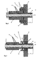
- FIG. 1 In the presentation of the FIG. 1 is a first embodiment of the device 1 according to the invention for connecting a conduit member 2 with a component 3 to recognize.
- the conduit element 2 is shown by way of example as a section of a corrugated hose.
- the reference numeral 3 here denotes the interior of the component 3
- only one wall 4 is shown explicitly in the illustration.
- the device 1 has a connection housing 5.
- This connection housing 5 has a flange 6, which via two fastening screws 7 with the wall 4th the component 3 is screwed.
- the connecting housing 5 is thus detachably connected to the component 3.
- a sealing element 8 is provided in the form of a sealing ring in the region of the flange 6.
- the connecting housing 5 may be made of an injection molding material, for example.
- the conduit element 2 is integrated into the injection-molding material of the connection housing 5 in such a way that the connection housing 5 is firmly and inseparably connected to the conduit element 2.
- a conduit section 9 which represents the continuation of the conduit element 2 within the connection housing 5 and in which the transported media can flow.
- the line section 9 can also be designed in one piece with the line element 2, thus forming one end.
- This line section 9 is surrounded by a heating wire 10, which serves for heating at least the line section 9.
- the heating wire 9 is electrically contacted via two indicated electrical connection elements 11. These electrical connection elements 11 can be easily and simply contacted in the region of the typically stationary stationary connection housing 5.
- the heating can then be continued accordingly, for example in a manner known and customary in the prior art.
- a heating wire not shown here in the region of the conduit member 2 can be connected to the heating wire 10 in the region of the line section 9, so that the entire Conduit 2 can be supplied via the electrical connection elements 11 with electrical power for heating.
- connection housing 5 surrounds, as in the illustration of FIG. 1 can be seen, while the line section 9 together with the wound around the outer circumference of the line section 9 heating wire 10 and the structure so isolated to the outside. If the line section 9 itself is also formed of an electrically non-conductive material, then the heating wire 10 can be used without further insulation measures or the like are necessary, since this then electrically insulating and mechanically protected between the line section 9 and the material of the connection housing 5 safe and reliable in its position.
- the inwardly projecting by the amount X line section 9 can also ensure that on the inside of the wall 4 of the component 3 optionally condensing liquid when descending on the wall does not penetrate into the line section 9, but around this in the region of the inner surface of the wall 4th expires. This ensures secure and reliable functionality. Due to the comparatively simple structure, which can be attached, for example, as an injection molded part to prefabricated and in particular heatable line elements 2, with a correspondingly high number of the connecting housing 5 and a suitable injection mold simple, safe and reliable high functionality of the structure can be made possible at very low cost ,
- connection housing 5 is fastened in the region of the component 3 or its wall 4.
- a receptacle 12 is provided here in the region of the wall 4.
- the line section 9 together with the surrounding material of the connecting housing 5 via two radial sealing elements 8 in the form of a double Sealed ring seal.
- the connecting housing 5 is then held by a mechanical lock 13 in the region of the receptacle 12 so that it can be inserted and fixed by the mechanical lock 13.
- the receptacle 12 may, for example, by a thread 14, as in the illustration of FIG. 2 indicated, be included in the area of the wall 4 of the component 3.
- Alternative configurations with a receptacle 12 welded into the wall 4 or a receptacle 12 glued to the wall 4 of the component 3 would of course also be conceivable.
- the structure of the device 1, as shown in the illustration of FIG. 2 can be seen, essentially the same, since here in the region of the connecting housing 5, the line section 9 is surrounded as a heated line section of the heating wire 10 and a medium flow through the conduit member 2 and the conduit section 9 into the interior of the component 3 in heat or thaw can.
Landscapes
- Engineering & Computer Science (AREA)
- General Engineering & Computer Science (AREA)
- Mechanical Engineering (AREA)
- Manufacturing & Machinery (AREA)
- Sustainable Development (AREA)
- Chemical & Material Sciences (AREA)
- Chemical Kinetics & Catalysis (AREA)
- Electrochemistry (AREA)
- General Chemical & Material Sciences (AREA)
- Sustainable Energy (AREA)
- Life Sciences & Earth Sciences (AREA)
- Pipe Accessories (AREA)
- Joints With Sleeves (AREA)
- Flanged Joints, Insulating Joints, And Other Joints (AREA)
Description
- Die Erfindung betrifft eine Vorrichtung zum Verbinden eines Leitungselements mit einer Komponente nach der im Oberbegriff von Anspruch 1 näher definierten Art. Außerdem betrifft die Erfindung ein Brennstoffzellensystem mit wenigstens einer Komponente, welches ein derartiges Leitungselement aufweist.
- Aus der
DE 10 2007 009 898 A1 ist ein Heizsystem für ein Rohr oder einen Schlauch in einem Brennstoffzellensystem bekannt. Um zu verhindern, dass Wasser in dem Rohr oder Schlauch gefriert, ist ein Heizdraht vorgesehen, welcher in Kontakt mit dem Rohr oder Schlauch steht. Dieses ist beispielsweise mit einem Heizdraht umwickelt, welcher über eine Schutzschicht an dem Rohr befestigt ist. Außerdem kann eine thermische Isolierung vorgesehen sein. - Die Problematik bei diesem Aufbau liegt nun darin, dass das Rohr selbst beheizt werden kann. Im Bereich von eventuellen Verbindungselementen wird die Beheizung dabei schwierig, insbesondere wenn das beheizte Leitungselement an eine unbeheizte Komponente, beispielsweise einen Brennstoffzellenstack, einen Reaktor, einen Wasserabscheider oder Ähnliches, angeschlossen wird. In diesem Bereich kann es dann zu einer Auskondensation und zum Gefrieren von flüssigem Wasser kommen, da lediglich die umgebenden Rohrleitungen beheizt werden können und dieser Bereich der Verbindung nicht beheizt ist.
- Aus der
US 3 612 577 ist eine Vorrichtung zum Verbinden eines Leitungselements mit einer Komponente offenbart, die alle Merkmale des Oberbegriffs des Anspruchs 1 enthält. - Es ist daher die Aufgabe der hier vorliegenden Erfindung eine Vorrichtung zum Verbinden eines Leitungselements mit einer Komponente zu schaffen, welche so ausgebildet ist, dass sie die oben genannten Nachteile vermeidet und eine Verbindung sicherstellt, welche das Auskondensieren und das eventuelle Einfrieren von Flüssigkeit aus dem in dem Leitungselement geförderten Medium vermeidet.
- Erfindungsgemäß wird diese Aufgabe durch die Vorrichtung mit den Merkmalen im kennzeichnenden Teil des Anspruchs 1 gelöst. Weitere vorteilhafte Ausgestaltungen der erfindungsgemäßen Vorrichtung ergeben sich dabei aus den restlichen abhängigen Unteransprüchen. Außerdem löst ein Brennstoffzellensystem gemäß Anspruch 11 die oben genannte Aufgabe.
- Die erfindungsgemäße Vorrichtung zum Verbinden eines Leitungselements mit einer Komponente sieht vor, dass das Leitungselement in einem Verbindungsgehäuse endet oder mit einem solchen fest verbunden ist. Dieses Verbindungsgehäuse selbst weist dann geeignete Mittel zur lösbaren Befestigung an der Komponente auf. Dies können beispielsweise herkömmliche Schraubenmittel sein, welche mit einem Flansch zusammenwirken. Außerdem wären andere lösbare Verbindungsmittel denkbar, beispielsweise Steckverbindungen mit mechanischer Verriegelung, wie sie insbesondere über das SAE-Papier J 2044 beschrieben werden.
- Erfindungsgemäß ist es dabei vorgesehen, dass ein im Verbindungsgehäuse verlaufender Leitungsabschnitt über einen elektrischen Heizdraht, welcher diesen von außen umgibt, beheizt ist. Der beheizte Leitungsabschnitt ragt dabei in Richtung der Komponente so weit über den Bereich zur lösbaren Befestigung des Verbindungsgehäuses an der Komponente hinaus, dass der Leitungsabschnitt in dem Innenraum der Komponente endet.
- Die erfindungsgemäße Vorrichtung ermöglicht es so, die zu transportierenden Medien auch im Bereich der Komponentenschnittstelle beziehungsweise der Anbindung des Leitungselements an eine Komponente zu beheizen beziehungsweise gegebenenfalls in diesem Bereich gefrorenes Medium aufzutauen. Durch den Überstand des Leitungsabschnitts in den Innenraum der Komponente kann außerdem erreicht werden, dass im Bereich der gegebenenfalls kühlen Wand der Komponente entstehendes auskondensierendes Medium beim Herabrinnen entlang der Wand nicht in das Leitungselement beziehungsweise den Leitungsabschnitt eindringt. Dadurch kann der sichere und zuverlässige Transport von Medien mit dem Leitungselement zu der Komponenten sichergestellt werden.
- In einer besonders günstigen und vorteilhaften Weiterbildung der Erfindung ist es dabei vorgesehen, dass das Material des Verbindungsgehäuses den beheizten Leitungsabschnitt und den Heizdraht auf der gesamten Länge des Leitungsabschnitts umschließt. Der Leitungsabschnitt kann so entsprechend von außen mit dem Heizdraht umwickelt werden, sodass keine Reaktion eines im Leitungsabschnitt geführten Mediums mit dem gegebenenfalls sehr heißen Heizdraht auftreten kann. Außerdem kann dadurch, dass das Material des Verbindungsgehäuses sowohl den Heizdraht als auch den Leitungsabschnitt umgibt, dieser entsprechend gegen Beschädigungen geschützt werden. Das Verbindungsgehäuse beziehungsweise das Material des Verbindungsgehäuses bildet so eine Schutzschicht um den mit dem Heizdraht versehenen Leitungsabschnitt. Dieser ist dann vor mechanischen Beschädigungen geschützt, sodass die Beheizung sicher und zuverlässig gewährleistet werden kann.
- In einer weiteren vorteilhaften Ausgestaltung der erfindungsgemäßen Vorrichtung ist es außerdem vorgesehen, dass das Verbindungsgehäuse aus einem elektrisch nicht leitenden Material ausgebildet ist. Ein solches Verbindungsgehäuse aus einem elektrisch nicht leitenden Material kann zusätzlich oder alternativ zu dem oben genannten mechanischen Schutz des Leitungselements und/oder Heizdrahts außerdem eine elektrische Isolierung des Heizdrahts gegenüber der Umgebung übernehmen, sodass neben dem Heizdraht und dem Leitungsabschnitt lediglich das Material des Verbindungsgehäuses als dritte Schicht notwendig ist. Der Aufbau ist entsprechend einfach und kann kostengünstig realisiert werden.
- In einer vorteilhaften Weiterbildung der erfindungsgemäßen Vorrichtung ist es ferner vorgesehen, dass das Verbindungsgehäuse einstückig mit dem Leitungselement ausgebildet ist. Ein solcher Aufbau kann beispielsweise dann genutzt werden, wenn Leitungselemente mit vorgefertigter Länge in vergleichsweise großen Stückzahlen eingesetzt werden. Dann lässt sich das Leitungselement und das Verbindungsgehäuse leicht einstückig ausbilden, sodass im Bereich, in dem das Leitungselement in das Verbindungsgehäuse übergeht, keine zusätzlichen Schnittstellen entstehen, welche hinsichtlich Dichtheit und gegebenenfalls hinsichtlich der Weiterleitung von elektrischer Heizleistung aus dem Bereich des Verbindungsgehäuses in den Bereich des Leitungselements kritisch sein könnten.
- In einer besonders günstigen Ausgestaltung der erfindungsgemäßen Vorrichtung kann es außerdem vorgesehen sein, dass das Verbindungsgehäuse als Spritzgussteil ausgebildet ist, welches ein Ende des Leitungselements und den Leitungsabschnitt am Außenumfang umschließt. Ein solcher Aufbau als Spritzgussteil, insbesondere aus Kunststoff, kann einfach genutzt werden, um ein vergleichsweise stabiles und kostengünstiges Verbindungsgehäuse herzustellen, wenn entsprechend hohe Stückzahlen für das Verbindungsgehäuse benötigt werden. Dadurch, dass das Verbindungsgehäuse beziehungsweise das Spritzgussmaterial des Verbindungsgehäuses ein Ende des Leitungselements und den Leitungsabschnitt vollständig umschließt, kann durch diesen Aufbau sehr einfach und effizient eine dichte Verbindung hergestellt werden. Außerdem kann der Leitungsabschnitt zusammen mit den Heizdrähten in das Spritzgussteil mit eingebettet werden, sofern dieser Aufbau in der oben geschilderten Variante verwendet werden soll. Dann entsteht mit einem einzigen Arbeitsgang an einer Spritzgussmaschine ein Bauteil, welches alle der bisher genannten Varianten und Vorteile in sich vereint.
- Wie oben bereits angedeutet, kann in einer weiteren sehr vorteilhaften Ausgestaltung der erfindungsgemäßen Vorrichtung das Leitungselement selbst ebenfalls elektrisch beheizt ausgebildet sein. Dabei kann es besonders sinnvoll und vorteilhaft sein, wenn die elektrische Beheizung sowohl des Leitungselements als auch des Verbindungsgehäuses so gestaltet ist, dass der im Bereich des Leitungsabschnitts verlaufende Heizdraht auch mit einem im Bereich des Leitungselements verlaufenden Heizdraht verbunden ist.
- In einer sehr günstigen und vorteilhaften Weiterführung der Idee kann es dabei vorgesehen sein, dass die elektrischen Anschlüsse für den Heizdraht im Bereich des Verbindungsgehäuses nach außen geführt sind. Dies ermöglicht den elektrischen Anschluss des Heizdrahts im Bereich des Verbindungsgehäuses. Da dieses mit einer Komponente lösbar verbunden ist, ist dieses während des Betriebs eines mit der Vorrichtung ausgestatteten Systems im Allgemeinen an einem fest vorgegebenen Ort und wird anders als beispielsweise ein als Schlauch ausgebildetes Leitungselement sich typischerweise nicht durch Vibrationen und Ähnliches bewegen. Dadurch kann in diesem Bereich ein Anbringen der elektrischen Anschlusselemente vergleichsweise einfach, sicher und zuverlässig erfolgen, ohne dass diese durch fortwährende Bewegungen der Gefahr einer Beschädigung ausgesetzt sind.
- Wie oben bereits erwähnt, löst auch ein Brennstoffzellensystem mit wenigstens einer Komponente die eingangs gestellte Aufgabe. Dieses erfindungsgemäße Brennstoffzellensystem sieht es dann vor, dass die wenigstens eine Komponente mittels einer Vorrichtung nach einer der bereits beschriebenen Ausgestaltungen mit einem Leitungselement verbunden ist. Wie bereits aus dem eingangs erwähnten Stand der Technik bekannt, ist es insbesondere bei Brennstoffzellensystemen, in denen Wasser als Produktwasser und zur Befeuchtung von Membranen in hochreiner Form anfällt beziehungsweise benötigt wird, besonders kritisch, wenn diese Systeme bei Temperaturen unterhalb des Gefrierpunkts betrieben werden. Da dies bei Fahrzeugen in vielen Regionen der Welt jedoch unvermeidbar ist, spielt die erfindungsgemäß ausgestaltete Vorrichtung bei derartigen Brennstoffzellensystemen eine besonders vorteilhafte Rolle.
- Weitere vorteilhafte Ausgestaltungen der erfindungsgemäßen Vorrichtung ergeben sich ferner aus den restlichen abhängigen Unteransprüchen und werden anhand der Ausführungsbeispiele deutlich, welche nachfolgend unter Bezugnahme auf die Figuren näher erläutert werden.
- Dabei zeigen:
-
Fig. 1 eine erste Ausführungsform der erfindungsgemäßen Vorrichtung; und -
Fig. 2 eine zweite Ausführungsform der erfindungsgemäßen Vorrichtung. - Die erfindungsgemäße Vorrichtung soll nachfolgend anhand der beiden Figuren in zwei möglichen Ausführungsbeispielen beschrieben werden. Der Aufbau kann beispielsweise in Brennstoffzellensystemen, aber auch in allen anderen Systemen, in denen beheizte Leitungen über Schnittstellen mit Komponenten verbunden sind, eine Beheizung sicherstellen.
- In der Darstellung der
Figur 1 ist eine erste Ausführungsform der erfindungsgemäßen Vorrichtung 1 zum Verbinden eines Leitungselements 2 mit einer Komponente 3 zu erkennen. Das Leitungselement 2 ist dabei beispielhaft als Abschnitt eines Wellschlauchs dargestellt. Von der Komponente 3, wobei das Bezugszeichen 3 hier das Innere der Komponente 3 bezeichnet, ist in der Darstellung lediglich eine Wand 4 explizit dargestellt. Die Vorrichtung 1 weist ein Verbindungsgehäuse 5 auf. Dieses Verbindungsgehäuse 5 weist einen Flansch 6 auf, welcher über zwei Befestigungsschrauben 7 mit der Wand 4 der Komponente 3 verschraubt ist. Das Verbindungsgehäuse 5 ist damit lösbar mit der Komponente 3 verbunden. Zur Abdichtung ist im Bereich des Flanschs 6 ein Dichtungselement 8 in Form eines Dichtrings vorgesehen. Das Verbindungsgehäuse 5 kann beispielsweise aus einem Spritzgussmaterial ausgeführt sein. In dem hier dargestellten Ausführungsbeispiel ist das Leitungselement 2 dabei so in das Spritzgussmaterial des Verbindungsgehäuses 5 integriert, dass das Verbindungsgehäuse 5 fest und unlösbar mit dem Leitungselement 2 verbunden ist. Im Inneren des Leitungselements 2 findet sich dabei ein Leitungsabschnitt 9, welcher innerhalb des Verbindungsgehäuses 5 die Fortführung des Leitungselements 2 darstellt und in dem die transportierten Medien strömen können. Der Leitungsabschnitt 9 kann auch einstückig mit dem Leitungselement 2 ausgeführt sein, also sein eines Ende bilden. Dieser Leitungsabschnitt 9 ist dabei von einem Heizdraht 10 umgeben, welcher zur Beheizung zumindest des Leitungsabschnitts 9 dient. In dem dargestellten Ausführungsbeispiel ist der Heizdraht 9 dabei über zwei angedeutete elektrische Anschlusselemente 11 elektrisch kontaktiert. Diese elektrischen Anschlusselemente 11 können dabei im Bereich des typischerweise ortsfest verharrenden Verbindungsgehäuses 5 leicht und einfach kontaktiert werden. Im Bereich des Leitungselements 2, welches sowohl als starres als auch als flexibles Leitungselement ausgeführt sein kann, kann die Beheizung dann entsprechend fortgesetzt sein, beispielsweise in einer Art und Weise, wie dies aus dem Stand der Technik bekannt und üblich ist. Um zu verhindern, dass die elektrischen Anschlüsse, insbesondere wenn das Leitungselement 2 als Schlauch ausgebildet ist, ständigen Bewegungen ausgesetzt sind, kann ein hier nicht dargestellter Heizdraht im Bereich des Leitungselements 2 mit dem Heizdraht 10 im Bereich des Leitungsabschnitts 9 verbunden werden, sodass das gesamte Leitungselement 2 über die elektrischen Anschlusselemente 11 mit elektrischer Leistung zur Beheizung versorgt werden kann. - Das Spritzgussmaterial des Verbindungsgehäuses 5 umgibt, wie in der Darstellung der
Figur 1 zu erkennen ist, dabei den Leitungsabschnitt 9 zusammen mit den um den Außenumfang des Leitungsabschnitts 9 gewickelten Heizdraht 10 und isoliert den Aufbau so nach außen. Wenn der Leitungsabschnitt 9 selbst ebenfalls aus einem elektrisch nicht leitenden Material ausgebildet ist, dann kann der Heizdraht 10 eingesetzt werden, ohne dass weitere Isolationsmaßnahmen oder dergleichen notwendig sind, da dieser dann zwischen dem Leitungsabschnitt 9 und dem Material des Verbindungsgehäuses 5 elektrisch isolierend und mechanisch geschützt sicher und zuverlässig in seiner Position gehalten wird. - In der Darstellung der
Figur 1 ist außerdem zu erkennen, dass der Leitungsabschnitt 9 in Richtung des Innenraums der Komponente 3 so weit über das eigentliche Verbindungsgehäuse 5 beziehungsweise den Flansch 6 hinaussteht, dass dieser durch die Wand 4 der Komponente 3 hindurchragt und um einen gewissen, in der Darstellung derFigur 1 mit X bezeichneten Wegabschnitt, in das Innere der Komponente 3 hineinragt. Durch diesen besonderen Aufbau des Verbindungsgehäuses 5 mit dem elektrisch beheizten Leitungselement 9 wird nicht nur der Bereich der Leitung elektrisch beheizt, sondern insbesondere der vergleichsweise kritische Bereich an der Verbindungsstelle zwischen dem Leitungselement 2 und einer Komponente 3. Dadurch, dass der Leitungsabschnitt 9 in das Innere der Komponente 3 hineinragt, erfolgt die Beheizung sicher und zuverlässig, bis das über das Leitungselement 2 und den Leitungsabschnitt 9 geführte Medium das Innere der Komponente 3 erreicht hat. Der um den Betrag X nach innen ragende Leitungsabschnitt 9 kann außerdem sicherstellen, dass an der Innenseite der Wand 4 der Komponente 3 gegebenenfalls auskondensierende Flüssigkeit beim Herabrinnen an der Wand nicht in den Leitungsabschnitt 9 eindringt, sondern um diesen herum im Bereich der Innenfläche der Wand 4 abläuft. Dadurch wird eine sichere und zuverlässige Funktionalität sichergestellt. Aufgrund des vergleichsweise einfachen Aufbaus, welcher beispielsweise als Spritzgussteil an vorkonfektionierte und insbesondere beheizbare Leitungselemente 2 mit angebracht werden kann, kann bei entsprechend hoher Stückzahl der Verbindungsgehäuse 5 und einem geeigneten Spritzgusswerkzeug einfach, sicher und zuverlässig eine hohe Funktionalität des Aufbaus bei sehr geringen Kosten ermöglicht werden. - In der Darstellung der
Figur 2 ist eine alternative Ausführungsform der erfindungsgemäßen Vorrichtung 1 zu erkennen. Der Aufbau ist dabei so ausgeführt, dass die Funktionalität im Wesentlichen dieselbe ist. Die mit denselben Bezugszeichen versehenen Bauteile entsprechen dabei den im Rahmen derFigur 1 beschriebenen Bauteilen. Der Unterschied zwischen den beiden Ausgestaltungen gemäß denFiguren 1 und 2 liegt darin, wie das Verbindungsgehäuse 5 im Bereich der Komponente 3 beziehungsweise ihrer Wand 4 befestigt wird. Anstelle der oben beschriebenen Befestigungsschrauben 7, welche mit dem Flansch 6 zusammenwirken, ist hier im Bereich der Wand 4 eine Aufnahme 12 vorgesehen. Im Bereich dieser Aufnahme 12 wird der Leitungsabschnitt 9 zusammen mit dem ihn umgebenden Material des Verbindungsgehäuses 5 über zwei radiale Dichtelemente 8 in Form einer doppelten Ringdichtung abgedichtet. Das Verbindungsgehäuse 5 ist dann über eine mechanische Verriegelung 13 so im Bereich der Aufnahme 12 gehalten, dass dieses eingesteckt und durch die mechanische Verriegelung 13 fixiert werden kann. Diese kann beispielsweise in Anlehnung an SAE J 2044 ausgeführt sein. Die Aufnahme 12 kann dabei beispielsweise durch ein Gewinde 14, wie in der Darstellung derFigur 2 angedeutet, im Bereich der Wand 4 der Komponente 3 aufgenommen werden. Alternative Ausgestaltungen mit einer in die Wand 4 eingeschweißten Aufnahme 12 oder einer mit der Wand 4 der Komponente 3 verklebten Aufnahme 12 wären selbstverständlich ebenso denkbar. - Ansonsten ist der Aufbau der Vorrichtung 1, wie sie in der Darstellung der
Figur 2 zu erkennen ist, im Wesentlichen derselbe, da auch hier im Bereich des Verbindungsgehäuses 5 der Leitungsabschnitt 9 als beheizter Leitungsabschnitt von dem Heizdraht 10 umgeben ist und einen Medienstrom durch das Leitungselement 2 und den Leitungsabschnitt 9 bis in das Innere der Komponente 3 hinein beheizen oder auftauen kann.
Claims (11)
- Vorrichtung zum Verbinden eines Leitungselements mit einer Komponente, wobei das Leitungselement in einem Verbindungsgehäuse endet oder mit einem solchen fest verbunden ist, und wobei zwischen dem Verbindungsgehäuse und der Komponente Mittel zur lösbaren Befestigung vorgesehen sind, wobei
ein im Verbindungsgehäuse (5) verlaufender Leitungsabschnitt (9) über einen elektrischen Heizdraht (10), welcher den Leitungsabschnitt (9) von außen umgibt, beheizt ist, dadurch gekennzeichnet, dass der beheizte Leitungsabschnitt (9) in Richtung der Komponente (3) so weit über den Bereich zur lösbaren Befestigung des Verbindungsgehäuses (5) an der Komponente (3) hinausragt, dass dieser in dem Innenraum der Komponente (3) endet. - Vorrichtung nach Anspruch 1,
dadurch gekennzeichnet, dass
das Material des Verbindungsgehäuses (5) den beheizten Leitungsabschnitt (9) und den Heizdraht (10) auf der gesamten Länge des Leitungsabschnitts (9) umschließt. - Vorrichtung nach Anspruch 1 oder 2,
dadurch gekennzeichnet, dass
das Verbindungsgehäuse (5) aus einem elektrisch nicht leitenden Material ausgebildet ist. - Vorrichtung nach Anspruch 1, 2 oder 3,
dadurch gekennzeichnet, dass
das Verbindungsgehäuse (5) einstückig mit dem Leitungselement (2) ausgebildet ist. - Vorrichtung nach einem der Ansprüche 1 bis 4,
dadurch gekennzeichnet, dass
das Verbindungsgehäuse (5) als Spritzgussteil ausgebildet ist, welches ein Ende des Leitungselements (2) und den Leitungsabschnitt (9) am Außenumfang umschließt. - Vorrichtung nach einem der Ansprüche 1 bis 5,
dadurch gekennzeichnet, dass
zwischen dem Verbindungsgehäuse (5) und der Komponente (3) Dichtungselemente (8) angeordnet sind. - Vorrichtung nach einem der Ansprüche 1 bis 6,
dadurch gekennzeichnet dass
das Verbindungsgehäuse (5) über einen Flansch (6) an einem Gehäuse der Komponente (3) befestigbar ist. - Vorrichtung nach einem der Ansprüche 1 bis 6,
dadurch gekennzeichnet, dass
das Verbindungsgehäuse (5) im Bereich des Gehäuses der Komponente (3) oder einer damit verbundenen Aufnahme (12) positioniert und über eine mechanische Verriegelung (13) gehalten ist. - Vorrichtung nach einem der Ansprüche 1 bis 8,
dadurch gekennzeichnet, dass
das Leitungselement (2) über einen Heizdraht elektrisch beheizt ausgebildet ist. - Vorrichtung nach einem der Ansprüche 1 bis 9,
dadurch gekennzeichnet, dass
elektrische Anschlusselemente (11) für den Heizdraht/die Heizdrähte (10) im Bereich des Verbindungsgehäuses (5) nach außen geführt sind. - Brennstoffzellensystem mit wenigstens einer Komponente (3), welche mittels einer Vorrichtung (1) nach einem der Ansprüche 1 bis 10 mit einem Leitungselement (2) verbunden ist.
Applications Claiming Priority (2)
| Application Number | Priority Date | Filing Date | Title |
|---|---|---|---|
| DE102010026827A DE102010026827A1 (de) | 2010-07-12 | 2010-07-12 | Vorrichtung zum Verbinden eines Leitungselements mit einer Komponente |
| PCT/EP2011/003250 WO2012007109A1 (de) | 2010-07-12 | 2011-06-30 | Vorrichtung zum verbinden eines leitungselements mit einer komponente |
Publications (2)
| Publication Number | Publication Date |
|---|---|
| EP2593706A1 EP2593706A1 (de) | 2013-05-22 |
| EP2593706B1 true EP2593706B1 (de) | 2014-08-13 |
Family
ID=44352313
Family Applications (1)
| Application Number | Title | Priority Date | Filing Date |
|---|---|---|---|
| EP11729919.8A Active EP2593706B1 (de) | 2010-07-12 | 2011-06-30 | Vorrichtung zum verbinden eines leitungselements mit einer komponente |
Country Status (6)
| Country | Link |
|---|---|
| US (1) | US9147988B2 (de) |
| EP (1) | EP2593706B1 (de) |
| JP (1) | JP5677569B2 (de) |
| CN (1) | CN102985745B (de) |
| DE (1) | DE102010026827A1 (de) |
| WO (1) | WO2012007109A1 (de) |
Cited By (1)
| Publication number | Priority date | Publication date | Assignee | Title |
|---|---|---|---|---|
| KR102881711B1 (ko) * | 2025-02-05 | 2025-11-07 | 주식회사 토르 | 반도체 공장 배기 배관의 층간 타공부의 발열 구조물 및 이의 시공방법 |
Families Citing this family (11)
| Publication number | Priority date | Publication date | Assignee | Title |
|---|---|---|---|---|
| DE202012101885U1 (de) * | 2012-05-23 | 2012-06-15 | TI Automotive (Fuldabrück) GmbH | Aggregat aus einem Verbinder und einer Medienleitung |
| DE102012020055A1 (de) * | 2012-10-12 | 2014-04-17 | Voss Automotive Gmbh | Elektrisch beheizbare Medienleitung sowie Verfahren zum Herstellen einer solchen |
| CN105972351A (zh) * | 2016-05-23 | 2016-09-28 | 苏州杰姆斯特机械有限公司 | 一种用于智慧城市给排管道寒冻的节能连接方法 |
| CN109994220B (zh) * | 2017-12-29 | 2024-03-19 | 核工业西南物理研究院 | 一种用于聚变堆真空侧的双层带电水路贯穿件 |
| GB2572553A (en) | 2018-03-29 | 2019-10-09 | Airbus Operations Ltd | Aircraft fuel tank isolator |
| EP3560674A1 (de) * | 2018-05-17 | 2019-10-30 | Brita GmbH | Leitung für einen flüssigkeitsspender, verfahren zu ihrer herstellung und ihre verwendung |
| CN109600871B (zh) * | 2018-12-03 | 2025-05-13 | 广东汇晶新能源科技有限公司 | 液体加热装置的发热管 |
| JP7333285B2 (ja) * | 2020-03-17 | 2023-08-24 | 本田技研工業株式会社 | 燃料電池システム |
| CN114294501B (zh) * | 2021-12-15 | 2024-07-26 | 武汉船用电力推进装置研究所(中国船舶重工集团公司第七一二研究所) | 一种高压海水穿舱管路结构及方法 |
| US11454336B1 (en) * | 2021-12-30 | 2022-09-27 | Ub Eng Co., Ltd. | Support device of vacuum pipe |
| CN115325279B (zh) * | 2022-07-07 | 2023-04-14 | 中铁建设集团有限公司 | 防渗组件及建筑外墙穿墙结构 |
Family Cites Families (11)
| Publication number | Priority date | Publication date | Assignee | Title |
|---|---|---|---|---|
| GB1283919A (en) * | 1968-10-30 | 1972-08-02 | Mirrlees Blackstone Ltd | Coaxial pipes with couplings |
| JPS5650223Y2 (de) * | 1977-09-07 | 1981-11-24 | ||
| US4653541A (en) * | 1985-06-26 | 1987-03-31 | Parker Hannifin Corporation | Dual wall safety tube |
| EP0312204A3 (de) * | 1987-10-09 | 1991-07-17 | Raychem Limited | Heizung eines Rohres mit leitfähigem Polymer |
| JP2794081B2 (ja) * | 1994-03-15 | 1998-09-03 | 工業技術院長 | 燃料電池発電システム |
| JPH10231970A (ja) * | 1997-02-21 | 1998-09-02 | Mitsubishi Heavy Ind Ltd | 真空断熱配管継手 |
| JP4418201B2 (ja) * | 2003-09-30 | 2010-02-17 | ニチアス株式会社 | 配管の断熱保温構造および断熱保温用具キット |
| SE0401557D0 (sv) * | 2004-06-15 | 2004-06-15 | Volvo Lastvagnar Ab | Elektrisk uppvärmningsbart kopplingsstycke samt inkapslad vätskeslang med elektriskt uppvärmningsbart kopplingsstycke |
| US20070036528A1 (en) * | 2005-07-29 | 2007-02-15 | William Ferrone | Heated hose electrical cord |
| US20070212037A1 (en) | 2006-03-03 | 2007-09-13 | Andreas Koenekamp | Heating element and mounting for media piping of fuel cell systems |
| CN101476659B (zh) * | 2009-02-05 | 2012-06-20 | 南京奥联汽车电子电器有限公司 | 一种用以输送发动机废气后处理介质的管路 |
-
2010
- 2010-07-12 DE DE102010026827A patent/DE102010026827A1/de not_active Withdrawn
-
2011
- 2011-06-30 EP EP11729919.8A patent/EP2593706B1/de active Active
- 2011-06-30 JP JP2013518974A patent/JP5677569B2/ja active Active
- 2011-06-30 WO PCT/EP2011/003250 patent/WO2012007109A1/de not_active Ceased
- 2011-06-30 CN CN201180034281.7A patent/CN102985745B/zh active Active
- 2011-06-30 US US13/809,730 patent/US9147988B2/en active Active
Cited By (1)
| Publication number | Priority date | Publication date | Assignee | Title |
|---|---|---|---|---|
| KR102881711B1 (ko) * | 2025-02-05 | 2025-11-07 | 주식회사 토르 | 반도체 공장 배기 배관의 층간 타공부의 발열 구조물 및 이의 시공방법 |
Also Published As
| Publication number | Publication date |
|---|---|
| JP2013538319A (ja) | 2013-10-10 |
| CN102985745B (zh) | 2015-02-25 |
| EP2593706A1 (de) | 2013-05-22 |
| WO2012007109A1 (de) | 2012-01-19 |
| US9147988B2 (en) | 2015-09-29 |
| DE102010026827A1 (de) | 2012-01-12 |
| CN102985745A (zh) | 2013-03-20 |
| US20130130143A1 (en) | 2013-05-23 |
| JP5677569B2 (ja) | 2015-02-25 |
Similar Documents
| Publication | Publication Date | Title |
|---|---|---|
| EP2593706B1 (de) | Vorrichtung zum verbinden eines leitungselements mit einer komponente | |
| EP2679874B1 (de) | Elektrisch beheizbare Medienleitung mit Leitungsverbinder | |
| EP2816272B1 (de) | Beheizbare Fluidleitung, deren Verwendung sowie Verfahren zu ihrer Herstellung | |
| EP2022142B1 (de) | Steckverbinder | |
| EP2766651B1 (de) | Konfektionierte medienleitung mit zumindest einer beheizbaren medienleitung und mit zumindest einem zumindest teilweise beheizbaren leitungsverbinder | |
| EP2641006A2 (de) | Konfektionierte elektrisch beheizbare medienleitung sowie verfahren zum herstellen einer solchen medienleitung | |
| DE102008025299A1 (de) | Anschlussvorrichtung für medienführende, elektrisch beheizbare Schläuche | |
| EP2129885B1 (de) | Beheizbare leitung | |
| DE202011106751U1 (de) | Zumindest teilweise beheizbarer Leitungsverbinder für eine beheizbare Medienleitung sowie konfektionierte Medienleitung mit einem solchen Leitungsverbinder | |
| DE102014005817A1 (de) | Mehrteilige beheizbare Medienleitung, Leitungsverbindungseinrichtung für eine solche sowie Verfahren zum Herstellen einer solchen | |
| DE102016118163A1 (de) | Lösbare verbindungseinrichtung für hohe ströme | |
| EP2420715B1 (de) | Isolations- und/oder Schutzabdeckung für beheizbare Leitungsverbinder | |
| EP2795749B1 (de) | Brandschutzvorrichtung | |
| DE102013016855B4 (de) | Mehrteilige Leitung | |
| EP2741375B1 (de) | Dichtungsvorrichtung, Verbinder und Herstellungsverfahren | |
| DE10212413B4 (de) | Waschwasserschlauch und Steckverbinder | |
| WO2022106723A1 (de) | Steckdose mit einem aktuator zur führung eines verriegelungselements | |
| DE102020130936A1 (de) | Steckdose mit einem Aktuator zur Führung eines Verriegelungselements | |
| DE102019216506A1 (de) | Atemluft-Führungs-Baugruppe für ein Patienten-Beatmungssystem | |
| DE202007019332U1 (de) | Beheizbare Leitung | |
| DE102014204270B4 (de) | Anordnung aus schlauchartiger Kraftstoffleitung und elektrisch leitfähigem Kontaktelement | |
| EP2658038B1 (de) | Schutzvorrichtung und Verfahren zur Herstellung einer Schutzvorrichtung | |
| DE102009056863A1 (de) | Vorrichtung zur Erfassung der Wasserstoffkonzentration | |
| DE102018115905B4 (de) | Elektromaschinenkomponente, insbesondere für ein Elektrofahrzeug | |
| WO2024246171A1 (de) | Elektrofahrzeug-ladekabel |
Legal Events
| Date | Code | Title | Description |
|---|---|---|---|
| PUAI | Public reference made under article 153(3) epc to a published international application that has entered the european phase |
Free format text: ORIGINAL CODE: 0009012 |
|
| 17P | Request for examination filed |
Effective date: 20121116 |
|
| AK | Designated contracting states |
Kind code of ref document: A1 Designated state(s): AL AT BE BG CH CY CZ DE DK EE ES FI FR GB GR HR HU IE IS IT LI LT LU LV MC MK MT NL NO PL PT RO RS SE SI SK SM TR |
|
| DAX | Request for extension of the european patent (deleted) | ||
| GRAP | Despatch of communication of intention to grant a patent |
Free format text: ORIGINAL CODE: EPIDOSNIGR1 |
|
| INTG | Intention to grant announced |
Effective date: 20140228 |
|
| GRAS | Grant fee paid |
Free format text: ORIGINAL CODE: EPIDOSNIGR3 |
|
| GRAA | (expected) grant |
Free format text: ORIGINAL CODE: 0009210 |
|
| AK | Designated contracting states |
Kind code of ref document: B1 Designated state(s): AL AT BE BG CH CY CZ DE DK EE ES FI FR GB GR HR HU IE IS IT LI LT LU LV MC MK MT NL NO PL PT RO RS SE SI SK SM TR |
|
| REG | Reference to a national code |
Ref country code: GB Ref legal event code: FG4D Free format text: NOT ENGLISH |
|
| REG | Reference to a national code |
Ref country code: AT Ref legal event code: REF Ref document number: 682464 Country of ref document: AT Kind code of ref document: T Effective date: 20140815 Ref country code: CH Ref legal event code: EP |
|
| REG | Reference to a national code |
Ref country code: IE Ref legal event code: FG4D Free format text: LANGUAGE OF EP DOCUMENT: GERMAN |
|
| REG | Reference to a national code |
Ref country code: DE Ref legal event code: R096 Ref document number: 502011004052 Country of ref document: DE Effective date: 20140925 |
|
| REG | Reference to a national code |
Ref country code: NL Ref legal event code: VDEP Effective date: 20140813 |
|
| REG | Reference to a national code |
Ref country code: LT Ref legal event code: MG4D |
|
| PG25 | Lapsed in a contracting state [announced via postgrant information from national office to epo] |
Ref country code: LT Free format text: LAPSE BECAUSE OF FAILURE TO SUBMIT A TRANSLATION OF THE DESCRIPTION OR TO PAY THE FEE WITHIN THE PRESCRIBED TIME-LIMIT Effective date: 20140813 Ref country code: NO Free format text: LAPSE BECAUSE OF FAILURE TO SUBMIT A TRANSLATION OF THE DESCRIPTION OR TO PAY THE FEE WITHIN THE PRESCRIBED TIME-LIMIT Effective date: 20141113 Ref country code: BG Free format text: LAPSE BECAUSE OF FAILURE TO SUBMIT A TRANSLATION OF THE DESCRIPTION OR TO PAY THE FEE WITHIN THE PRESCRIBED TIME-LIMIT Effective date: 20141113 Ref country code: ES Free format text: LAPSE BECAUSE OF FAILURE TO SUBMIT A TRANSLATION OF THE DESCRIPTION OR TO PAY THE FEE WITHIN THE PRESCRIBED TIME-LIMIT Effective date: 20140813 Ref country code: GR Free format text: LAPSE BECAUSE OF FAILURE TO SUBMIT A TRANSLATION OF THE DESCRIPTION OR TO PAY THE FEE WITHIN THE PRESCRIBED TIME-LIMIT Effective date: 20141114 Ref country code: SE Free format text: LAPSE BECAUSE OF FAILURE TO SUBMIT A TRANSLATION OF THE DESCRIPTION OR TO PAY THE FEE WITHIN THE PRESCRIBED TIME-LIMIT Effective date: 20140813 Ref country code: FI Free format text: LAPSE BECAUSE OF FAILURE TO SUBMIT A TRANSLATION OF THE DESCRIPTION OR TO PAY THE FEE WITHIN THE PRESCRIBED TIME-LIMIT Effective date: 20140813 Ref country code: PT Free format text: LAPSE BECAUSE OF FAILURE TO SUBMIT A TRANSLATION OF THE DESCRIPTION OR TO PAY THE FEE WITHIN THE PRESCRIBED TIME-LIMIT Effective date: 20141215 |
|
| PG25 | Lapsed in a contracting state [announced via postgrant information from national office to epo] |
Ref country code: LV Free format text: LAPSE BECAUSE OF FAILURE TO SUBMIT A TRANSLATION OF THE DESCRIPTION OR TO PAY THE FEE WITHIN THE PRESCRIBED TIME-LIMIT Effective date: 20140813 Ref country code: HR Free format text: LAPSE BECAUSE OF FAILURE TO SUBMIT A TRANSLATION OF THE DESCRIPTION OR TO PAY THE FEE WITHIN THE PRESCRIBED TIME-LIMIT Effective date: 20140813 Ref country code: RS Free format text: LAPSE BECAUSE OF FAILURE TO SUBMIT A TRANSLATION OF THE DESCRIPTION OR TO PAY THE FEE WITHIN THE PRESCRIBED TIME-LIMIT Effective date: 20140813 Ref country code: IS Free format text: LAPSE BECAUSE OF FAILURE TO SUBMIT A TRANSLATION OF THE DESCRIPTION OR TO PAY THE FEE WITHIN THE PRESCRIBED TIME-LIMIT Effective date: 20141213 Ref country code: CY Free format text: LAPSE BECAUSE OF FAILURE TO SUBMIT A TRANSLATION OF THE DESCRIPTION OR TO PAY THE FEE WITHIN THE PRESCRIBED TIME-LIMIT Effective date: 20140813 |
|
| PG25 | Lapsed in a contracting state [announced via postgrant information from national office to epo] |
Ref country code: NL Free format text: LAPSE BECAUSE OF FAILURE TO SUBMIT A TRANSLATION OF THE DESCRIPTION OR TO PAY THE FEE WITHIN THE PRESCRIBED TIME-LIMIT Effective date: 20140813 |
|
| PG25 | Lapsed in a contracting state [announced via postgrant information from national office to epo] |
Ref country code: SK Free format text: LAPSE BECAUSE OF FAILURE TO SUBMIT A TRANSLATION OF THE DESCRIPTION OR TO PAY THE FEE WITHIN THE PRESCRIBED TIME-LIMIT Effective date: 20140813 Ref country code: DK Free format text: LAPSE BECAUSE OF FAILURE TO SUBMIT A TRANSLATION OF THE DESCRIPTION OR TO PAY THE FEE WITHIN THE PRESCRIBED TIME-LIMIT Effective date: 20140813 Ref country code: CZ Free format text: LAPSE BECAUSE OF FAILURE TO SUBMIT A TRANSLATION OF THE DESCRIPTION OR TO PAY THE FEE WITHIN THE PRESCRIBED TIME-LIMIT Effective date: 20140813 Ref country code: RO Free format text: LAPSE BECAUSE OF FAILURE TO SUBMIT A TRANSLATION OF THE DESCRIPTION OR TO PAY THE FEE WITHIN THE PRESCRIBED TIME-LIMIT Effective date: 20140813 Ref country code: EE Free format text: LAPSE BECAUSE OF FAILURE TO SUBMIT A TRANSLATION OF THE DESCRIPTION OR TO PAY THE FEE WITHIN THE PRESCRIBED TIME-LIMIT Effective date: 20140813 Ref country code: IT Free format text: LAPSE BECAUSE OF FAILURE TO SUBMIT A TRANSLATION OF THE DESCRIPTION OR TO PAY THE FEE WITHIN THE PRESCRIBED TIME-LIMIT Effective date: 20140813 |
|
| REG | Reference to a national code |
Ref country code: DE Ref legal event code: R097 Ref document number: 502011004052 Country of ref document: DE |
|
| PG25 | Lapsed in a contracting state [announced via postgrant information from national office to epo] |
Ref country code: PL Free format text: LAPSE BECAUSE OF FAILURE TO SUBMIT A TRANSLATION OF THE DESCRIPTION OR TO PAY THE FEE WITHIN THE PRESCRIBED TIME-LIMIT Effective date: 20140813 |
|
| PLBE | No opposition filed within time limit |
Free format text: ORIGINAL CODE: 0009261 |
|
| STAA | Information on the status of an ep patent application or granted ep patent |
Free format text: STATUS: NO OPPOSITION FILED WITHIN TIME LIMIT |
|
| 26N | No opposition filed |
Effective date: 20150515 |
|
| PG25 | Lapsed in a contracting state [announced via postgrant information from national office to epo] |
Ref country code: SI Free format text: LAPSE BECAUSE OF FAILURE TO SUBMIT A TRANSLATION OF THE DESCRIPTION OR TO PAY THE FEE WITHIN THE PRESCRIBED TIME-LIMIT Effective date: 20140813 |
|
| PG25 | Lapsed in a contracting state [announced via postgrant information from national office to epo] |
Ref country code: MC Free format text: LAPSE BECAUSE OF FAILURE TO SUBMIT A TRANSLATION OF THE DESCRIPTION OR TO PAY THE FEE WITHIN THE PRESCRIBED TIME-LIMIT Effective date: 20140813 |
|
| REG | Reference to a national code |
Ref country code: CH Ref legal event code: PL |
|
| PG25 | Lapsed in a contracting state [announced via postgrant information from national office to epo] |
Ref country code: LU Free format text: LAPSE BECAUSE OF FAILURE TO SUBMIT A TRANSLATION OF THE DESCRIPTION OR TO PAY THE FEE WITHIN THE PRESCRIBED TIME-LIMIT Effective date: 20150630 |
|
| REG | Reference to a national code |
Ref country code: IE Ref legal event code: MM4A |
|
| PG25 | Lapsed in a contracting state [announced via postgrant information from national office to epo] |
Ref country code: CH Free format text: LAPSE BECAUSE OF NON-PAYMENT OF DUE FEES Effective date: 20150630 Ref country code: IE Free format text: LAPSE BECAUSE OF NON-PAYMENT OF DUE FEES Effective date: 20150630 Ref country code: LI Free format text: LAPSE BECAUSE OF NON-PAYMENT OF DUE FEES Effective date: 20150630 |
|
| REG | Reference to a national code |
Ref country code: FR Ref legal event code: PLFP Year of fee payment: 6 |
|
| PGFP | Annual fee paid to national office [announced via postgrant information from national office to epo] |
Ref country code: GB Payment date: 20160630 Year of fee payment: 6 |
|
| PGFP | Annual fee paid to national office [announced via postgrant information from national office to epo] |
Ref country code: FR Payment date: 20160630 Year of fee payment: 6 |
|
| PG25 | Lapsed in a contracting state [announced via postgrant information from national office to epo] |
Ref country code: MT Free format text: LAPSE BECAUSE OF FAILURE TO SUBMIT A TRANSLATION OF THE DESCRIPTION OR TO PAY THE FEE WITHIN THE PRESCRIBED TIME-LIMIT Effective date: 20140813 |
|
| PG25 | Lapsed in a contracting state [announced via postgrant information from national office to epo] |
Ref country code: SM Free format text: LAPSE BECAUSE OF FAILURE TO SUBMIT A TRANSLATION OF THE DESCRIPTION OR TO PAY THE FEE WITHIN THE PRESCRIBED TIME-LIMIT Effective date: 20140813 Ref country code: HU Free format text: LAPSE BECAUSE OF FAILURE TO SUBMIT A TRANSLATION OF THE DESCRIPTION OR TO PAY THE FEE WITHIN THE PRESCRIBED TIME-LIMIT; INVALID AB INITIO Effective date: 20110630 |
|
| PG25 | Lapsed in a contracting state [announced via postgrant information from national office to epo] |
Ref country code: BE Free format text: LAPSE BECAUSE OF NON-PAYMENT OF DUE FEES Effective date: 20150630 |
|
| REG | Reference to a national code |
Ref country code: AT Ref legal event code: MM01 Ref document number: 682464 Country of ref document: AT Kind code of ref document: T Effective date: 20160630 |
|
| PG25 | Lapsed in a contracting state [announced via postgrant information from national office to epo] |
Ref country code: TR Free format text: LAPSE BECAUSE OF FAILURE TO SUBMIT A TRANSLATION OF THE DESCRIPTION OR TO PAY THE FEE WITHIN THE PRESCRIBED TIME-LIMIT Effective date: 20140813 |
|
| PG25 | Lapsed in a contracting state [announced via postgrant information from national office to epo] |
Ref country code: AT Free format text: LAPSE BECAUSE OF NON-PAYMENT OF DUE FEES Effective date: 20160630 |
|
| GBPC | Gb: european patent ceased through non-payment of renewal fee |
Effective date: 20170630 |
|
| REG | Reference to a national code |
Ref country code: FR Ref legal event code: ST Effective date: 20180228 |
|
| PG25 | Lapsed in a contracting state [announced via postgrant information from national office to epo] |
Ref country code: GB Free format text: LAPSE BECAUSE OF NON-PAYMENT OF DUE FEES Effective date: 20170630 |
|
| PG25 | Lapsed in a contracting state [announced via postgrant information from national office to epo] |
Ref country code: FR Free format text: LAPSE BECAUSE OF NON-PAYMENT OF DUE FEES Effective date: 20170630 |
|
| PG25 | Lapsed in a contracting state [announced via postgrant information from national office to epo] |
Ref country code: MK Free format text: LAPSE BECAUSE OF FAILURE TO SUBMIT A TRANSLATION OF THE DESCRIPTION OR TO PAY THE FEE WITHIN THE PRESCRIBED TIME-LIMIT Effective date: 20140813 |
|
| PG25 | Lapsed in a contracting state [announced via postgrant information from national office to epo] |
Ref country code: AL Free format text: LAPSE BECAUSE OF FAILURE TO SUBMIT A TRANSLATION OF THE DESCRIPTION OR TO PAY THE FEE WITHIN THE PRESCRIBED TIME-LIMIT Effective date: 20140813 |
|
| REG | Reference to a national code |
Ref country code: DE Ref legal event code: R081 Ref document number: 502011004052 Country of ref document: DE Owner name: CELLCENTRIC GMBH & CO. KG, DE Free format text: FORMER OWNER: DAIMLER AG, 70327 STUTTGART, DE Ref country code: DE Ref legal event code: R082 Ref document number: 502011004052 Country of ref document: DE Representative=s name: JENSEN & SON, GB Ref country code: DE Ref legal event code: R081 Ref document number: 502011004052 Country of ref document: DE Owner name: DAIMLER AG, DE Free format text: FORMER OWNER: DAIMLER AG, 70327 STUTTGART, DE Ref country code: DE Ref legal event code: R082 Ref document number: 502011004052 Country of ref document: DE Representative=s name: JENSENS IP LIMITED, IE |
|
| REG | Reference to a national code |
Ref country code: DE Ref legal event code: R082 Ref document number: 502011004052 Country of ref document: DE Representative=s name: WALLINGER RICKER SCHLOTTER TOSTMANN PATENT- UN, DE Ref country code: DE Ref legal event code: R082 Ref document number: 502011004052 Country of ref document: DE Representative=s name: PLATZOEDER PATENTANWALTSGESELLSCHAFT MBH, DE Ref country code: DE Ref legal event code: R082 Ref document number: 502011004052 Country of ref document: DE Representative=s name: JENSENS IP LIMITED, IE |
|
| REG | Reference to a national code |
Ref country code: DE Ref legal event code: R081 Ref document number: 502011004052 Country of ref document: DE Owner name: CELLCENTRIC GMBH & CO. KG, DE Free format text: FORMER OWNER: DAIMLER AG, STUTTGART, DE Ref country code: DE Ref legal event code: R082 Ref document number: 502011004052 Country of ref document: DE Representative=s name: WALLINGER RICKER SCHLOTTER TOSTMANN PATENT- UN, DE Ref country code: DE Ref legal event code: R082 Ref document number: 502011004052 Country of ref document: DE Representative=s name: PLATZOEDER PATENTANWALTSGESELLSCHAFT MBH, DE |
|
| REG | Reference to a national code |
Ref country code: DE Ref legal event code: R082 Ref document number: 502011004052 Country of ref document: DE Representative=s name: WALLINGER RICKER SCHLOTTER TOSTMANN PATENT- UN, DE Ref country code: DE Ref legal event code: R082 Ref document number: 502011004052 Country of ref document: DE Representative=s name: PLATZOEDER PATENTANWALTSGESELLSCHAFT MBH, DE |
|
| REG | Reference to a national code |
Ref country code: DE Ref legal event code: R082 Ref document number: 502011004052 Country of ref document: DE Representative=s name: PLATZOEDER PATENTANWALTSGESELLSCHAFT MBH, DE |
|
| PGFP | Annual fee paid to national office [announced via postgrant information from national office to epo] |
Ref country code: DE Payment date: 20250618 Year of fee payment: 15 |