EP2594184B1 - Geschirrspüler - Google Patents
Geschirrspüler Download PDFInfo
- Publication number
- EP2594184B1 EP2594184B1 EP11806442.7A EP11806442A EP2594184B1 EP 2594184 B1 EP2594184 B1 EP 2594184B1 EP 11806442 A EP11806442 A EP 11806442A EP 2594184 B1 EP2594184 B1 EP 2594184B1
- Authority
- EP
- European Patent Office
- Prior art keywords
- washing tub
- housing
- rail
- dishwasher
- attachment member
- Prior art date
- Legal status (The legal status is an assumption and is not a legal conclusion. Google has not performed a legal analysis and makes no representation as to the accuracy of the status listed.)
- Not-in-force
Links
- 238000005406 washing Methods 0.000 claims description 107
- 230000007246 mechanism Effects 0.000 claims description 34
- XLYOFNOQVPJJNP-UHFFFAOYSA-N water Substances O XLYOFNOQVPJJNP-UHFFFAOYSA-N 0.000 description 8
- 230000002093 peripheral effect Effects 0.000 description 7
- 229910000831 Steel Inorganic materials 0.000 description 5
- 239000010959 steel Substances 0.000 description 5
- 238000005452 bending Methods 0.000 description 4
- 238000005304 joining Methods 0.000 description 4
- 239000002184 metal Substances 0.000 description 4
- 230000000694 effects Effects 0.000 description 3
- 239000011347 resin Substances 0.000 description 3
- 229920005989 resin Polymers 0.000 description 3
- 238000004519 manufacturing process Methods 0.000 description 2
- 238000000465 moulding Methods 0.000 description 2
- 238000005096 rolling process Methods 0.000 description 2
- 238000004851 dishwashing Methods 0.000 description 1
- 239000000463 material Substances 0.000 description 1
- 238000000034 method Methods 0.000 description 1
- 230000035515 penetration Effects 0.000 description 1
- 238000003825 pressing Methods 0.000 description 1
- 238000007789 sealing Methods 0.000 description 1
- 238000005507 spraying Methods 0.000 description 1
Images


Classifications
-
- A—HUMAN NECESSITIES
- A47—FURNITURE; DOMESTIC ARTICLES OR APPLIANCES; COFFEE MILLS; SPICE MILLS; SUCTION CLEANERS IN GENERAL
- A47L—DOMESTIC WASHING OR CLEANING; SUCTION CLEANERS IN GENERAL
- A47L15/00—Washing or rinsing machines for crockery or tableware
- A47L15/42—Details
-
- A—HUMAN NECESSITIES
- A47—FURNITURE; DOMESTIC ARTICLES OR APPLIANCES; COFFEE MILLS; SPICE MILLS; SUCTION CLEANERS IN GENERAL
- A47L—DOMESTIC WASHING OR CLEANING; SUCTION CLEANERS IN GENERAL
- A47L15/00—Washing or rinsing machines for crockery or tableware
- A47L15/0084—Washing or rinsing machines for crockery or tableware of drawer-type
-
- A—HUMAN NECESSITIES
- A47—FURNITURE; DOMESTIC ARTICLES OR APPLIANCES; COFFEE MILLS; SPICE MILLS; SUCTION CLEANERS IN GENERAL
- A47L—DOMESTIC WASHING OR CLEANING; SUCTION CLEANERS IN GENERAL
- A47L15/00—Washing or rinsing machines for crockery or tableware
-
- A—HUMAN NECESSITIES
- A47—FURNITURE; DOMESTIC ARTICLES OR APPLIANCES; COFFEE MILLS; SPICE MILLS; SUCTION CLEANERS IN GENERAL
- A47L—DOMESTIC WASHING OR CLEANING; SUCTION CLEANERS IN GENERAL
- A47L15/00—Washing or rinsing machines for crockery or tableware
- A47L15/42—Details
- A47L15/50—Racks ; Baskets
- A47L15/507—Arrangements for extracting racks, e.g. roller supports
Definitions
- the present invention relates to a built-in type dishwasher for washing dishes by spraying washing water from a washing nozzle toward the dishes.
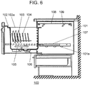
- a configuration of conventional dishwasher 100 will be described.
- FIG. 6 is a side view showing an internal configuration of conventional dishwasher 100
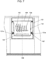
- FIG. 7 is a front view thereof.
- dishwasher 100 is accommodated in a kitchen unit, and includes washing tub 102 inside metal housing 101 having an opening on a front side.
- Washing tub 102 has opening 102a on an upper side, and interiorly includes washing basket 104 for accommodating dishes 103.
- Washing nozzle 105 is rotatably arranged beneath washing basket 104, where washing water accumulated in washing tub 102 is circulated by washing pump 106 and sprayed from washing nozzle 105 to wash dishes 103.
- Slide mechanism 107 which is configured by a rail or the like, is fixed at a side of washing tub 102, so that washing tub 102 is supported so as to be movable in parallel in a front and back direction.
- washing tub 102 When putting in or taking out dishes 103, a user pulls out washing tub 102 forward from housing 101, and accommodates dishes 103 through opening 102a. The user then returns and accommodates washing tub 102 in housing 101. Lid body 108, which is waiting in an upper space in housing 101, then lowers while moving backward by means of link mechanism 109 or the like arranged on an inner side surface of housing 101, thus closing opening 102a of washing tub 102.
- Metal housing 101 is made of a thin rolled steel plate.
- Rail holding portion 101a is formed by performing press working on left and right side walls of housing 101.
- Rail holding portion 101a holds washing tub 102 accommodating dishes 103 by way of slide mechanism 107 (refer to PTL 1, for example).
- PTL2 discloses a dishwasher according to the preamble of claim 1.
- the present invention reinforces only the necessary portion of the housing in a dishwasher to be enlarged.
- the present invention provides a dishwasher having a housing structure that facilitates the work while ensuring the strength without increasing the cost.
- a dishwasher of the present invention includes a washing tub arranged in a housing that opens to a front side and for accommodating dishes to be washed, a slide mechanism attached on both sides of the washing tub and for supporting the washing tub so as to be movable in a front and back direction, and a rail attachment member for fixing the slide mechanism and the housing.
- a cross-sectional shape formed by the rail attachment member and the side walls of the housing is a rectangle or a box shape when the rail attachment member is attached to the housing.
- the housing structure that reinforces only the portion necessary for the housing of the dishwasher to be enlarged, and facilitates the work while ensuring strength without increasing the cost can be realized.
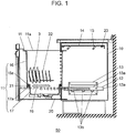
- FIG. 1 is a side view showing an internal configuration of dishwasher 50 according to an exemplary embodiment of the present invention
- FIG. 2 is a front view showing the internal configuration of dishwasher 50
- FIG. 3 is a front view showing a detailed configuration of a portion that supports washing tub 11 of dishwasher 50.
- dishwasher 50 includes washing tub 11 which accommodates dishes 3 as objects to be washed, and which is accommodated inside metal housing 10 having an opening on a front side. Washing tub 11 has opening 11a on an upper side.
- Washing tub 11 is held to be movable in a front and back direction by slide mechanism 12, which is fixed at a lower side on both sides of the washing tub.
- Slide mechanism 12 is supported by rail attachment member 13 provided on an inner side of left and right side walls 10a of housing 10.
- Slide mechanism 12 includes fixed rail portion 12a fixed to rail attachment member 13, and movable rail portion 12b fixed to washing tub 11.
- a plurality of rolling bodies 30 arranged between fixed rail portion 12a and movable rail portion 12b cause movable rail portion 12b to be movable in a longitudinal direction (front and back direction when incorporated in dishwasher 50) with respect to fixed rail portion 12a.
- a user When putting in or taking out dishes 3, a user pulls out washing tub 11 forward from housing 10, and puts in or takes out dishes 3 through opening 11a. The user then returns and accommodates washing tub 11 in housing 10.
- Lid body 14 water-tightly closes opening 11a of washing tub 11 by way of seal member 23 provided on an outer periphery of an inner surface of lid body 14.
- Metal housing 10 has left and right side walls 10a and bottom surface 10f integrally formed by performing bending work on a thin rolled steel plate.
- Rail attachment member supporting portion 10b that projects out inward is formed at plural areas of the same height position in left and right side walls 10a by performing the press working (more specifically, louver working in which the upper side is opened).
- Rail attachment member supporting portion 10b holds washing tub 11, in which dishes 3 are accommodated, from the lower side by way of rail attachment member 13 and slide mechanism 12.
- Dishwasher 50 is larger than the conventional dishwasher in width and in height.
- Rail attachment member 13 is formed long such that the cross-section has a substantially horseshoe shape (II in Greek letter) by performing bending work, or the like on the thin rolled steel plate, same as with housing 10.
- Rail attachment member 13 includes step portion 13a positioned on the inner side of housing 10 when attached to side wall 10a of housing 10.
- Rail attachment member 13 is configured such that the cross-sectional shape is a rectangle or a box shape when attached to housing 10.
- Rail holding portion 13b for supporting and holding fixed rail portion 12a of slide mechanism 12 from the lower side is integrally formed so as to project out inward by performing the press working (more specifically, louver working in which the upper side is opened) at plural areas in the lowermost portion of step portion 13a.
- Rail attachment member 13 includes upper flange portion 13c and lower flange portion 13d on upper side and lower side of the portion having a substantially horseshoe shaped cross-section. Rail attachment member 13 is fixed by a few screws with respect to side wall 10a of housing 10 at upper flange portion 13c and lower flange portion 13d.
- Upper attachment portion 10c that faces upper flange portion 13c of side wall 10a of housing 10 and lower attachment portion 10d that faces lower flange portion 13d are respectively subjected to press working to be formed in a manner recessed inward over substantially the entire length in a depth direction. This enhances the strength of side wall 10a.
- upper attachment portion 10c and lower attachment portion 10d have a difference in level in the degree of inward projection.
- upper attachment portion 10c is on the inner side of lower attachment portion 10d.
- rail attachment member 13 is configured such that upper flange portion 13c is on the inner side of lower flange portion 13d.
- Outward projection 10e formed by not performing the press working is provided between upper attachment portion 10c and lower attachment portion 10d. Outward projection 10e is also formed to project outward over substantially the entire length in the depth direction.
- Washing tub 11 is configured by resin washing tub member 16, which configures at least the side surface, and resin bottom portion configuring member 17, which configures at least the bottom portion.
- Bottom portion configuring member 17 is formed into a bottomed tray shape, and seal member 18 including an elastic body such as rubber is arranged at outer peripheral upper end 17a.
- Groove portion 17b which is opened to the upper side for holding seal member 18, is formed to an annular shape on outer peripheral upper end 17a.
- bottom portion configuring member 17 a large part of the electrical components and mechanism components necessary for the operation control of dishwasher 50 such as movable rail portion 12b of slide mechanism 12, washing nozzle 19, washing pump 20, and the like is mounted and formed as a unit.
- washing tub member 16 of a different size is attached to bottom portion configuring member 17, it can function as dishwasher 50.
- Seal rib 16b that holds down seal member 18 from the upper side and that exhibits water tightness in cooperation with groove portion 17b of bottom portion configuring member 17 is provided on outer peripheral lower end 16a at the front, back, left, and right of washing tub member 16.
- Outer peripheral upper end 17a of bottom portion configuring member 17 and outer peripheral lower end 16a of washing tub member 16 are joined in an up and down direction.
- the joining portion is provided with seal unit 21 configured by groove portion 17b, seal rib 16b, and seal member 18 to water-tightly seal the joining portion.
- Washing basket 22 that accommodates dishes 3 inside is arranged on the upper side of seal unit 21 in washing tub 11.
- Washing nozzle 19 is rotatably arranged on the lower side of washing basket 22, where the washing water accumulated in washing tub 11 is circulated by washing pump 20 and sprayed from washing nozzle 19 to wash dishes 3.
- dishwasher 50 configured as above will be described below.
- rail attachment member 13 has a difference in level in the width direction between upper flange portion 13c and lower flange portion 13d, and thus a pair of symmetrical parts are to be prepared.
- a pair of symmetrical slide mechanisms 12 are similarly positioned on rail attachment member 13 by bringing the bottom surface of fixed rail portion 12a into contact with the upper end face of rail holding portion 13b of rail attachment member 13. In this state, the side surface of fixed rail portion 12a is fixed to step portion 13a of rail attachment member 13 with a screw.
- the inner side surface of the upper surface of rail attachment member 13 is fixed with screws while being mounted on the upper end face of rail attachment member supporting potion 10b provided on side wall 10a of housing 10.
- the position in the height direction of slide mechanism 12 is thereby determined.
- Left and right slide mechanisms 12 are attached to left and right side walls 10a of housing 10 in such manner.
- washing tub 11 The assembly of washing tub 11 is carried out in the following manner. Washing tub member 16 is inserted from the upper side of bottom portion configuring member 17 set with seal member 18. Engagement portion 16d provided at a downward extending part of side wall portion 16c thus temporarily deforms by its own elasticity. Engagement hole 16e engages projection 17c arranged on bottom portion configuring member 17 thus enabling regulation in the up and down direction, and washing tub member 16 and bottom portion configuring member 17 are coupled and integrated to complete washing tub 11.
- seal rib 16b of washing tub member 16 pushes seal member 18 from the upper side and deforms it to a defined fastening position, thus forming seal unit 21 and water sealing the joining portion.
- washing tub 11 is mounted on movable rail portions 12b of left and right slide mechanisms 12 assembled to housing 10, and fixed with a screw or the like to movable rail portion 12b when the position in the depth direction is determined. Washing tub 11 is thus supported to be movable in the front and back direction with respect to housing 10.
- rail attachment member 13, which cross-section is substantially formed to a horseshoe shape, and side wall 10a of housing 10 form a rectangular or a box shaped cross-section.
- Outward projection 10e is formed at the portion of side wall 10a in which the cross-section is a rectangle or a box shape.
- dishwasher 50 With penetration of built-in type dishwasher 50 into the market, there is a growing need for enlargement. In order to respond to such a need, dishwasher 50 needs to have a larger outer contour or increase the capacity of dishes 3 that can be accommodated in washing tub 11.
- a defined space e.g., width of 450 mm, height of 800 mm
- the width of the outer contour first needs to be maximized in the defined space, and the height needs to be made as high as possible.
- the capacity is increased by increasing the width and the height of washing tub 11.
- Left and right side walls 10a of housing 10 configuring the outer contour of dishwasher 50 are formed by performing the bending work on the thin rolled steel plate.
- Side wall 10a requires the strength to respond to an increase in weight by the amount of increase in the capacity of dishes and the amount of washing water required to ensure the washing performance of increased dishes 3 by way of slide mechanism 12.
- rail attachment member 13 which cross-section is formed to a substantially horseshoe shape, is attached to side wall 10a, so that rail attachment member 13 and side wall 10a of housing 10 form a rectangular or a box shaped cross-section. Only the portion necessary for supporting washing tub 11 of increased weight thus can be reinforced. Thus, the strength with respect to the load can be enhanced without increasing the cost such as increasing the thickness of the rolled steel plate, which is the material.
- washing tub 11 has left and right side wall portions 16c of washing tub member 16 raised upward from the outermost periphery of seal unit 21.
- the internal capacity on the upper side of seal unit 21 can be enlarged and washing basket 22 can be arranged therein, whereby the capacity of dishes 3 to be accommodated can be increased.
- Rail attachment member 13 can be formed through a simple step of merely performing the bending work, and is configured such that the cross-sectional shape is a rectangle or a box shape when attached to side wall 10a of housing 10. A structure that can easily ensure strength is thereby realized.
- a side portion of rail attachment member 13 includes rail holding portion 13b that projects out inward while being attached to housing 10, and that supports slide mechanism 12 from the lower side.
- the load of washing tub 11 accommodating dishes 3 thus can be dispersed to rail holding portion 13b and upper attachment portion 10c and lower attachment portion 10d without being concentrated on upper attachment portion 10c and lower attachment portion 10d of side wall 10a of housing 10 fixed with screw.
- the configuration of the attachment portion by screw fixation thus can be simplified.
- Rail attachment member supporting portion 10b for determining the attachment height position of rail attachment member 13 and supporting rail attachment member 13 from the lower side is provided in housing 10 so as to project out inward from left and right side walls 10a.
- the variation in the height positions of left and right slide mechanisms 12 thus reduces, and the movement of washing tub 11 in the front and back direction becomes smooth.
- the load of washing tub 11 accommodating dishes 3 is supported at the upper end face of rail attachment member supporting portion 10b, thus suppressing the downward deformation of rail attachment member 13.
- the downward movement of washing tub 11 is thereby suppressed, and the water tightness of the portion that closes opening 11a on the upper side of washing tub 11 with lid body 14 can be ensured.
- Upper attachment portion 10c and lower attachment portion 10d formed to project out inward of left and right side walls 10a of housing 10 have a difference in level in the degree of inward projection.
- the portion for attaching rail attachment member 13 of side wall 10a of housing 10 thus can be effectively reinforced through simple work intensively and without increasing the cost.
- Outward projection 10e that projects out outward than upper attachment portion 10c and lower attachment portion 10d is provided between upper attachment portion 10c and lower attachment portion 10d of left and right side walls 10a of housing 10.
- the portion that forms a rectangular or a box shaped cross-section with rail attachment member 13 of side wall 10a of housing 10 can be reinforced through simple work intensively and without increasing the cost.
- Rail attachment member supporting portion 10b formed on left and right side walls 10a and rail holding portion 13b formed at the lowermost part of step portion 13a of rail attachment member 13 are both provided in plurals in the depth direction of dishwasher 50.
- at least one of rail attachment member supporting portion 10b or rail holding portion 13b may be formed as one projection that is long in the depth direction.
- rail attachment member supporting portion 10b is formed as one projection that is long in the depth direction, the effect of suppressing the downward deformation of the upper surface of rail attachment member 13 caused by the load of washing tub 11 accommodating dishes 3 can be increased.
- dishwasher 50 is configured by dividing washing tub 11 into washing tub member 16 and bottom portion configuring member 17. Furthermore, bottom portion configuring member 17 is formed as a unit with a large part of the electrical components and mechanism components mounted thereon.
- the washing tub of different capacities can be obtained even if single bottom portion configuring member 17 is used by making the portion on the upper side of seal unit 21 of washing tub member 16 larger or smaller. Therefore, the production of dishwasher 50 having different washing tub capacity can be easily responded, and the manufacturing efficiency can be enhanced.
- dishwasher 50 According to the present exemplary embodiment, Further characteristics of dishwasher 50 according to the present exemplary embodiment will now be described in comparison with another dishwasher 51 that uses same bottom portion configuring member 17.
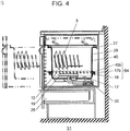
- FIG. 4 is a side view showing an internal configuration of a dishwasher not part of the present invention 51 using same bottom portion configuring member 17 according to the exemplary embodiment of the present invention
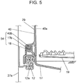
- FIG. 5 is a front view showing the main parts of the internal configuration of the dishwasher 51.
- the same reference numerals are denoted on the configurations same as dishwasher 50 such as bottom portion configuring member 17, and the description thereof will be omitted.
- dishwasher 51 is of a shallow type in which the depth of the washing tub is shallower than dishwasher 50 described above, and drawer 25 for accommodating kitchen goods, and the like is provided in a kitchen unit space below dishwasher 51.
- Such a shallow type dishwasher 51 and a deep type dishwasher 50 in which the depth of the washing tub is deep, described above, are prepared so that the user can select the preferred one when planning the kitchen unit, thus improving the convenience of the kitchen unit.
- Deep type dishwasher 50 appeals in that the amount of dishes 3 that can be accommodated in washing tub 11 is large. Thus, compared to shallow type dishwasher 51, not only is the depth deep, but the width dimension also needs to be as wide as possible. A width dimension of housing 10 and a width dimension of washing tub 11 are both set to be wider than those in shallow type dishwasher 51.
- dishwasher 50 has left and right side wall portions 16c of washing tub member 16 raised upward from the outermost periphery of seal unit 21 so that the width dimension of washing tub 11 becomes as large as possible.
- the internal capacity of washing tub 11 is thus made large to a maximum extent.
- opening 11a through which dishes 3 are put in or taken out at the uppermost part of washing tub member 16 needs to be closed with lid body 14.
- flange portion 16f needs to be provided so as to bulge out to the outer side of side wall portion 16c at a portion where lid body 14 makes contacts and closes through seal member 23 (see FIG. 2 ).
- washing tub member 40 which configures washing tub 29 by joining with bottom portion configuring member 17, has left and right side wall portions 40a raised upward from the innermost periphery of seal unit 54.
- the width dimension for the flange portion bulging out at the periphery of the opening at the uppermost part of washing tub member 40 thus can be ensured.
- fixed rail portion 12a of slide mechanism 12 can be directly attached to side wall 27a of housing 27.
- seal unit 54 including groove portion 17b, seal rib 40b, and seal member 18 is similar to seal unit 21 of the deep type dishwasher described above.
- Rail attachment member 13 intensively reinforces the necessary portion of left and right side walls 10a having high height in deep type dishwasher 50. Furthermore, rail attachment member 13 exhibits a large effect as a configuration for attaching fixed rail portion 12a of slide mechanism 12 to side wall 10a of housing 10 while ensuring the width dimension for flange portion 16f when commonly using bottom portion configuring member 17 with shallow type dishwasher 51.
- the housing structure that reinforces only the portion necessary for the housing of the dishwasher to be enlarged, and facilitates the work while ensuring strength without increasing the cost can be realized. It is thus useful as a built-in type dishwasher or the like in which the washing tub is pulled out to put in or take out the dishes.
Landscapes
- Washing And Drying Of Tableware (AREA)
Claims (5)
- Geschirrspülmaschine, umfassend:eine Spülwanne (11, 29), die in einem Gehäuse (10, 27) angeordnet ist, das zu einer Vorderseite geöffnet wird, und zum Aufnehmen von zu spülendem Geschirr (3);einen Gleitmechanismus (12), der an beiden Seite der Spülwanne angebracht ist und die Spülwanne stützt, sodass sie in eine Vorwärts- und Rückwärtsrichtung bewegt werden kann; undein Schienenbefestigungselement (13), das an dem Gehäuse angebracht ist (10, 27) und den Gleitmechanismus und das Gehäuse befestigt, wobeieine Querschnittsform, die durch das Schienenbefestigungselement (13) und die Seitenwände (10a, 27a) des Gehäuses (10, 27) gebildet ist, ein Rechteck oder eine Kastenform ist,dadurch gekennzeichnet, dassdas Schienenbefestigungselement (13) einen im Wesentlichen hufeisenförmigen Querschnitt hat und einen Schienenhalteabschnitt (13b) beinhaltet, der nach innen hervorsteht und den Gleitmechanisums (12) von einer unteren Seite an einem Seitenabschnitt stützt.
- Geschirrspülmaschine nach Anspruch 1, wobei
das Gehäuse einen Schienenbefestigungselement-Stützabschnitt (10b) beinhaltet, um eine Befestigungshöhenposition des Schienenbefestigungselements (13) zu bestimmen und das Schienenbefestigungselement (13) von einer unteren Seite zu stützen, und
der Schienenbefestigungselement-Stützabschnitt (10b) angeordnet ist, um von einer linken und einer rechten Seitenwand nach innen hervorzustehen. - Geschirrspülmaschine nach Anspruch 1, wobei
ein oberer Befestigungsabschnitt (10c) und ein unterer Befestigungsabschnitt (10d) zum Anbringen des Schienenbefestigungselements (13), das gebildet ist, um nach innen hervorzustehen, an einer linken und einer rechten Seitenwand des Gehäuses angeordnet sind, und
der obere Befestigungsabschnitt (10c) und der untere Befestigungsabschnitt (10d) einen Höhenunterschied in einem Grad eines nach innen gerichteten Vorsprungs haben. - Geschirrspülmaschine nach Anspruch 3, wobei
ein nach außen gerichteter Vorsprung (10e), der nach außen als der obere Befestigungsabschnitt (10c) und der untere Befestigungsabschnitt (10d) hervorsteht, zwischen dem oberen Befestigungsabschnitt (10c) und dem unteren Befestigungsabschnitt (10d) an der linken und der rechte Seitenwand des Gehäuses angeordnet ist. - Geschirrspülmaschine nach einem der vorstehenden Ansprüche 1 bis 4, wobei
die Spülwanne (11, 29) ein Bodenabschnitt-Konfigurationselement (17), das mindestens einen Bodenabschnitt der Spülwanne (11, 29) konfiguriert, und ein Spülwannenelement (16, 40), das mindestens eine Seitenfläche der Spülwanne konfiguriert, beinhaltet, und
der Gleitmechanismus (12) an dem Bodenabschnitt-Konfigurationselement (17) angebracht ist.
Applications Claiming Priority (2)
| Application Number | Priority Date | Filing Date | Title |
|---|---|---|---|
| JP2010157460A JP5445366B2 (ja) | 2010-07-12 | 2010-07-12 | 食器洗い機 |
| PCT/JP2011/003665 WO2012008105A1 (ja) | 2010-07-12 | 2011-06-28 | 食器洗い機 |
Publications (3)
| Publication Number | Publication Date |
|---|---|
| EP2594184A1 EP2594184A1 (de) | 2013-05-22 |
| EP2594184A4 EP2594184A4 (de) | 2017-10-11 |
| EP2594184B1 true EP2594184B1 (de) | 2018-08-08 |
Family
ID=45469125
Family Applications (1)
| Application Number | Title | Priority Date | Filing Date |
|---|---|---|---|
| EP11806442.7A Not-in-force EP2594184B1 (de) | 2010-07-12 | 2011-06-28 | Geschirrspüler |
Country Status (6)
| Country | Link |
|---|---|
| EP (1) | EP2594184B1 (de) |
| JP (1) | JP5445366B2 (de) |
| KR (1) | KR101441259B1 (de) |
| CN (1) | CN103002786B (de) |
| TW (1) | TWI513444B (de) |
| WO (1) | WO2012008105A1 (de) |
Families Citing this family (8)
| Publication number | Priority date | Publication date | Assignee | Title |
|---|---|---|---|---|
| CN104323747B (zh) * | 2014-11-18 | 2017-06-16 | 王金青 | 环保型洗碗机 |
| CN104305945B (zh) * | 2014-11-18 | 2017-06-30 | 王金青 | 推拉框式洗碗机 |
| CN104323749B (zh) * | 2014-11-18 | 2017-06-16 | 王金青 | 清洗消毒以及烘干一体化洗碗机 |
| JP6545041B2 (ja) * | 2015-08-25 | 2019-07-17 | リンナイ株式会社 | 食器洗浄機 |
| DE102017209824B3 (de) * | 2017-06-09 | 2018-09-20 | BSH Hausgeräte GmbH | Spülbehälter, Verfahren zum Herstellen eines Spülbehälters und Haushaltsgeschirrspülmaschine |
| CN108577740B (zh) * | 2018-05-02 | 2024-05-28 | 佛山市顺德区美的洗涤电器制造有限公司 | 内胆组件和洗碗机 |
| JP2020031793A (ja) * | 2018-08-28 | 2020-03-05 | リンナイ株式会社 | 食器洗浄機の外装ケース |
| KR102389692B1 (ko) | 2020-11-16 | 2022-04-22 | (주)한울 | 프라이머를 사용하지 않는 실리콘 커팅 시트지 제조장치 |
Family Cites Families (12)
| Publication number | Priority date | Publication date | Assignee | Title |
|---|---|---|---|---|
| JPS5214191Y2 (de) * | 1971-10-15 | 1977-03-30 | ||
| JPS5943301Y2 (ja) * | 1980-11-28 | 1984-12-21 | 三洋電機株式会社 | 洗浄機のコンベア用レ−ルの取付け構造 |
| JPS63138157U (de) * | 1987-03-03 | 1988-09-12 | ||
| DE3927214C2 (de) * | 1989-08-17 | 1995-09-07 | Miele & Cie | Frontseitig beschickbare Geschirrspülmaschine mit Geschirrkörben |
| JP3795349B2 (ja) * | 2001-06-20 | 2006-07-12 | リンナイ株式会社 | 引出式食器洗浄機 |
| JP3688262B2 (ja) * | 2002-11-05 | 2005-08-24 | 松下電器産業株式会社 | スライドレールの取付構造 |
| JP4249118B2 (ja) * | 2004-11-19 | 2009-04-02 | パナソニック株式会社 | 食器洗い機 |
| JP2007130362A (ja) * | 2005-11-14 | 2007-05-31 | Okamura Corp | 商品陳列装置 |
| ATE479380T1 (de) * | 2006-12-06 | 2010-09-15 | Electrolux Home Prod Corp | Geschirrspüler |
| JP4628398B2 (ja) * | 2007-05-29 | 2011-02-09 | リンナイ株式会社 | 引き出し式食器洗い機 |
| JP4958311B2 (ja) * | 2008-06-30 | 2012-06-20 | リンナイ株式会社 | 食器洗い機の合成樹脂製洗浄槽 |
| KR100995081B1 (ko) * | 2008-11-27 | 2010-12-03 | 범진시엔엘 주식회사 | 스피커 구조 |
-
2010
- 2010-07-12 JP JP2010157460A patent/JP5445366B2/ja active Active
-
2011
- 2011-06-28 EP EP11806442.7A patent/EP2594184B1/de not_active Not-in-force
- 2011-06-28 KR KR1020137000711A patent/KR101441259B1/ko active Active
- 2011-06-28 WO PCT/JP2011/003665 patent/WO2012008105A1/ja not_active Ceased
- 2011-06-28 TW TW100122650A patent/TWI513444B/zh active
- 2011-06-28 CN CN201180034481.2A patent/CN103002786B/zh active Active
Also Published As
| Publication number | Publication date |
|---|---|
| JP2012019807A (ja) | 2012-02-02 |
| KR101441259B1 (ko) | 2014-09-17 |
| TWI513444B (zh) | 2015-12-21 |
| EP2594184A4 (de) | 2017-10-11 |
| KR20130031328A (ko) | 2013-03-28 |
| EP2594184A1 (de) | 2013-05-22 |
| CN103002786A (zh) | 2013-03-27 |
| WO2012008105A1 (ja) | 2012-01-19 |
| TW201204303A (en) | 2012-02-01 |
| JP5445366B2 (ja) | 2014-03-19 |
| CN103002786B (zh) | 2015-03-04 |
Similar Documents
| Publication | Publication Date | Title |
|---|---|---|
| EP2594184B1 (de) | Geschirrspüler | |
| US11079170B2 (en) | Refrigerator having slide rail cabling mechanism | |
| US20180094375A1 (en) | Coupling system of removable compartment for appliances | |
| US8986463B2 (en) | Dishwasher operating panel seal | |
| EP4442183B1 (de) | Geschirrspülmaschine | |
| EP3015323A1 (de) | Wischerarm | |
| EP3345527B1 (de) | Frontplatte für eine tür für ein haushaltsgerät | |
| MX2007004666A (es) | Mecanismo de tapa para un lavavajillas de tipo gaveta. | |
| EP1810555B1 (de) | Fernüberwachungsgerät elektrischer heimgeräte | |
| CN214740954U (zh) | 翻盖用密封条、密封组件、翻盖式开闭结构、波轮洗衣机 | |
| KR100673957B1 (ko) | 휴대용 전자기기의 케이스 | |
| JP5759812B2 (ja) | カバーの接続構造およびカバーの接続方法 | |
| CN105371574A (zh) | 冰箱门体 | |
| CN211796293U (zh) | 洗碗机和洗涤设备 | |
| CN218523823U (zh) | 家用电器及其箱体的前盖 | |
| JP2008236847A (ja) | 電気接続箱 | |
| CN221533648U (zh) | 一种洗碗机的门体结构及洗碗机 | |
| EP2432365B1 (de) | Geschirrspülmaschine | |
| CN112294223B (zh) | 盖板和洗碗机 | |
| EP2798288B1 (de) | Haushaltsgerät mit einem griff | |
| US11412915B2 (en) | Dish washer with loading frame | |
| CN205119639U (zh) | 冰箱门体及具有该门体的冰箱 | |
| CN222251422U (zh) | 衣物处理设备 | |
| JP4515379B2 (ja) | 食器洗い機 | |
| CN212307593U (zh) | 煲体组件及具有其的烹饪器具 |
Legal Events
| Date | Code | Title | Description |
|---|---|---|---|
| PUAI | Public reference made under article 153(3) epc to a published international application that has entered the european phase |
Free format text: ORIGINAL CODE: 0009012 |
|
| 17P | Request for examination filed |
Effective date: 20121128 |
|
| AK | Designated contracting states |
Kind code of ref document: A1 Designated state(s): AL AT BE BG CH CY CZ DE DK EE ES FI FR GB GR HR HU IE IS IT LI LT LU LV MC MK MT NL NO PL PT RO RS SE SI SK SM TR |
|
| DAX | Request for extension of the european patent (deleted) | ||
| RA4 | Supplementary search report drawn up and despatched (corrected) |
Effective date: 20170908 |
|
| RIC1 | Information provided on ipc code assigned before grant |
Ipc: A47L 15/50 20060101ALI20170904BHEP Ipc: A47L 15/00 20060101AFI20170904BHEP |
|
| REG | Reference to a national code |
Ref country code: DE Ref legal event code: R079 Ref document number: 602011050898 Country of ref document: DE Free format text: PREVIOUS MAIN CLASS: A47L0015420000 Ipc: A47L0015000000 |
|
| GRAP | Despatch of communication of intention to grant a patent |
Free format text: ORIGINAL CODE: EPIDOSNIGR1 |
|
| STAA | Information on the status of an ep patent application or granted ep patent |
Free format text: STATUS: GRANT OF PATENT IS INTENDED |
|
| RIC1 | Information provided on ipc code assigned before grant |
Ipc: A47L 15/50 20060101ALI20180130BHEP Ipc: A47L 15/00 20060101AFI20180130BHEP |
|
| INTG | Intention to grant announced |
Effective date: 20180302 |
|
| GRAS | Grant fee paid |
Free format text: ORIGINAL CODE: EPIDOSNIGR3 |
|
| GRAA | (expected) grant |
Free format text: ORIGINAL CODE: 0009210 |
|
| STAA | Information on the status of an ep patent application or granted ep patent |
Free format text: STATUS: THE PATENT HAS BEEN GRANTED |
|
| AK | Designated contracting states |
Kind code of ref document: B1 Designated state(s): AL AT BE BG CH CY CZ DE DK EE ES FI FR GB GR HR HU IE IS IT LI LT LU LV MC MK MT NL NO PL PT RO RS SE SI SK SM TR |
|
| REG | Reference to a national code |
Ref country code: GB Ref legal event code: FG4D |
|
| REG | Reference to a national code |
Ref country code: CH Ref legal event code: EP Ref country code: AT Ref legal event code: REF Ref document number: 1026035 Country of ref document: AT Kind code of ref document: T Effective date: 20180815 |
|
| REG | Reference to a national code |
Ref country code: IE Ref legal event code: FG4D |
|
| REG | Reference to a national code |
Ref country code: DE Ref legal event code: R096 Ref document number: 602011050898 Country of ref document: DE |
|
| REG | Reference to a national code |
Ref country code: NL Ref legal event code: MP Effective date: 20180808 |
|
| REG | Reference to a national code |
Ref country code: LT Ref legal event code: MG4D |
|
| REG | Reference to a national code |
Ref country code: AT Ref legal event code: MK05 Ref document number: 1026035 Country of ref document: AT Kind code of ref document: T Effective date: 20180808 |
|
| PG25 | Lapsed in a contracting state [announced via postgrant information from national office to epo] |
Ref country code: FI Free format text: LAPSE BECAUSE OF FAILURE TO SUBMIT A TRANSLATION OF THE DESCRIPTION OR TO PAY THE FEE WITHIN THE PRESCRIBED TIME-LIMIT Effective date: 20180808 Ref country code: IS Free format text: LAPSE BECAUSE OF FAILURE TO SUBMIT A TRANSLATION OF THE DESCRIPTION OR TO PAY THE FEE WITHIN THE PRESCRIBED TIME-LIMIT Effective date: 20181208 Ref country code: PL Free format text: LAPSE BECAUSE OF FAILURE TO SUBMIT A TRANSLATION OF THE DESCRIPTION OR TO PAY THE FEE WITHIN THE PRESCRIBED TIME-LIMIT Effective date: 20180808 Ref country code: RS Free format text: LAPSE BECAUSE OF FAILURE TO SUBMIT A TRANSLATION OF THE DESCRIPTION OR TO PAY THE FEE WITHIN THE PRESCRIBED TIME-LIMIT Effective date: 20180808 Ref country code: SE Free format text: LAPSE BECAUSE OF FAILURE TO SUBMIT A TRANSLATION OF THE DESCRIPTION OR TO PAY THE FEE WITHIN THE PRESCRIBED TIME-LIMIT Effective date: 20180808 Ref country code: GR Free format text: LAPSE BECAUSE OF FAILURE TO SUBMIT A TRANSLATION OF THE DESCRIPTION OR TO PAY THE FEE WITHIN THE PRESCRIBED TIME-LIMIT Effective date: 20181109 Ref country code: NO Free format text: LAPSE BECAUSE OF FAILURE TO SUBMIT A TRANSLATION OF THE DESCRIPTION OR TO PAY THE FEE WITHIN THE PRESCRIBED TIME-LIMIT Effective date: 20181108 Ref country code: AT Free format text: LAPSE BECAUSE OF FAILURE TO SUBMIT A TRANSLATION OF THE DESCRIPTION OR TO PAY THE FEE WITHIN THE PRESCRIBED TIME-LIMIT Effective date: 20180808 Ref country code: LT Free format text: LAPSE BECAUSE OF FAILURE TO SUBMIT A TRANSLATION OF THE DESCRIPTION OR TO PAY THE FEE WITHIN THE PRESCRIBED TIME-LIMIT Effective date: 20180808 Ref country code: BG Free format text: LAPSE BECAUSE OF FAILURE TO SUBMIT A TRANSLATION OF THE DESCRIPTION OR TO PAY THE FEE WITHIN THE PRESCRIBED TIME-LIMIT Effective date: 20181108 Ref country code: NL Free format text: LAPSE BECAUSE OF FAILURE TO SUBMIT A TRANSLATION OF THE DESCRIPTION OR TO PAY THE FEE WITHIN THE PRESCRIBED TIME-LIMIT Effective date: 20180808 |
|
| PG25 | Lapsed in a contracting state [announced via postgrant information from national office to epo] |
Ref country code: LV Free format text: LAPSE BECAUSE OF FAILURE TO SUBMIT A TRANSLATION OF THE DESCRIPTION OR TO PAY THE FEE WITHIN THE PRESCRIBED TIME-LIMIT Effective date: 20180808 Ref country code: HR Free format text: LAPSE BECAUSE OF FAILURE TO SUBMIT A TRANSLATION OF THE DESCRIPTION OR TO PAY THE FEE WITHIN THE PRESCRIBED TIME-LIMIT Effective date: 20180808 Ref country code: AL Free format text: LAPSE BECAUSE OF FAILURE TO SUBMIT A TRANSLATION OF THE DESCRIPTION OR TO PAY THE FEE WITHIN THE PRESCRIBED TIME-LIMIT Effective date: 20180808 |
|
| PG25 | Lapsed in a contracting state [announced via postgrant information from national office to epo] |
Ref country code: RO Free format text: LAPSE BECAUSE OF FAILURE TO SUBMIT A TRANSLATION OF THE DESCRIPTION OR TO PAY THE FEE WITHIN THE PRESCRIBED TIME-LIMIT Effective date: 20180808 Ref country code: CZ Free format text: LAPSE BECAUSE OF FAILURE TO SUBMIT A TRANSLATION OF THE DESCRIPTION OR TO PAY THE FEE WITHIN THE PRESCRIBED TIME-LIMIT Effective date: 20180808 Ref country code: ES Free format text: LAPSE BECAUSE OF FAILURE TO SUBMIT A TRANSLATION OF THE DESCRIPTION OR TO PAY THE FEE WITHIN THE PRESCRIBED TIME-LIMIT Effective date: 20180808 Ref country code: EE Free format text: LAPSE BECAUSE OF FAILURE TO SUBMIT A TRANSLATION OF THE DESCRIPTION OR TO PAY THE FEE WITHIN THE PRESCRIBED TIME-LIMIT Effective date: 20180808 Ref country code: IT Free format text: LAPSE BECAUSE OF FAILURE TO SUBMIT A TRANSLATION OF THE DESCRIPTION OR TO PAY THE FEE WITHIN THE PRESCRIBED TIME-LIMIT Effective date: 20180808 |
|
| REG | Reference to a national code |
Ref country code: DE Ref legal event code: R097 Ref document number: 602011050898 Country of ref document: DE |
|
| PG25 | Lapsed in a contracting state [announced via postgrant information from national office to epo] |
Ref country code: DK Free format text: LAPSE BECAUSE OF FAILURE TO SUBMIT A TRANSLATION OF THE DESCRIPTION OR TO PAY THE FEE WITHIN THE PRESCRIBED TIME-LIMIT Effective date: 20180808 Ref country code: SK Free format text: LAPSE BECAUSE OF FAILURE TO SUBMIT A TRANSLATION OF THE DESCRIPTION OR TO PAY THE FEE WITHIN THE PRESCRIBED TIME-LIMIT Effective date: 20180808 Ref country code: SM Free format text: LAPSE BECAUSE OF FAILURE TO SUBMIT A TRANSLATION OF THE DESCRIPTION OR TO PAY THE FEE WITHIN THE PRESCRIBED TIME-LIMIT Effective date: 20180808 |
|
| PLBE | No opposition filed within time limit |
Free format text: ORIGINAL CODE: 0009261 |
|
| STAA | Information on the status of an ep patent application or granted ep patent |
Free format text: STATUS: NO OPPOSITION FILED WITHIN TIME LIMIT |
|
| 26N | No opposition filed |
Effective date: 20190509 |
|
| PG25 | Lapsed in a contracting state [announced via postgrant information from national office to epo] |
Ref country code: SI Free format text: LAPSE BECAUSE OF FAILURE TO SUBMIT A TRANSLATION OF THE DESCRIPTION OR TO PAY THE FEE WITHIN THE PRESCRIBED TIME-LIMIT Effective date: 20180808 |
|
| PG25 | Lapsed in a contracting state [announced via postgrant information from national office to epo] |
Ref country code: MC Free format text: LAPSE BECAUSE OF FAILURE TO SUBMIT A TRANSLATION OF THE DESCRIPTION OR TO PAY THE FEE WITHIN THE PRESCRIBED TIME-LIMIT Effective date: 20180808 |
|
| REG | Reference to a national code |
Ref country code: CH Ref legal event code: PL |
|
| GBPC | Gb: european patent ceased through non-payment of renewal fee |
Effective date: 20190628 |
|
| REG | Reference to a national code |
Ref country code: BE Ref legal event code: MM Effective date: 20190630 |
|
| PG25 | Lapsed in a contracting state [announced via postgrant information from national office to epo] |
Ref country code: TR Free format text: LAPSE BECAUSE OF FAILURE TO SUBMIT A TRANSLATION OF THE DESCRIPTION OR TO PAY THE FEE WITHIN THE PRESCRIBED TIME-LIMIT Effective date: 20180808 |
|
| PG25 | Lapsed in a contracting state [announced via postgrant information from national office to epo] |
Ref country code: GB Free format text: LAPSE BECAUSE OF NON-PAYMENT OF DUE FEES Effective date: 20190628 Ref country code: IE Free format text: LAPSE BECAUSE OF NON-PAYMENT OF DUE FEES Effective date: 20190628 |
|
| PG25 | Lapsed in a contracting state [announced via postgrant information from national office to epo] |
Ref country code: CH Free format text: LAPSE BECAUSE OF NON-PAYMENT OF DUE FEES Effective date: 20190630 Ref country code: LU Free format text: LAPSE BECAUSE OF NON-PAYMENT OF DUE FEES Effective date: 20190628 Ref country code: LI Free format text: LAPSE BECAUSE OF NON-PAYMENT OF DUE FEES Effective date: 20190630 Ref country code: BE Free format text: LAPSE BECAUSE OF NON-PAYMENT OF DUE FEES Effective date: 20190630 |
|
| PG25 | Lapsed in a contracting state [announced via postgrant information from national office to epo] |
Ref country code: PT Free format text: LAPSE BECAUSE OF FAILURE TO SUBMIT A TRANSLATION OF THE DESCRIPTION OR TO PAY THE FEE WITHIN THE PRESCRIBED TIME-LIMIT Effective date: 20181208 Ref country code: FR Free format text: LAPSE BECAUSE OF NON-PAYMENT OF DUE FEES Effective date: 20190630 |
|
| PGFP | Annual fee paid to national office [announced via postgrant information from national office to epo] |
Ref country code: DE Payment date: 20200618 Year of fee payment: 10 |
|
| PG25 | Lapsed in a contracting state [announced via postgrant information from national office to epo] |
Ref country code: CY Free format text: LAPSE BECAUSE OF FAILURE TO SUBMIT A TRANSLATION OF THE DESCRIPTION OR TO PAY THE FEE WITHIN THE PRESCRIBED TIME-LIMIT Effective date: 20180808 |
|
| PG25 | Lapsed in a contracting state [announced via postgrant information from national office to epo] |
Ref country code: HU Free format text: LAPSE BECAUSE OF FAILURE TO SUBMIT A TRANSLATION OF THE DESCRIPTION OR TO PAY THE FEE WITHIN THE PRESCRIBED TIME-LIMIT; INVALID AB INITIO Effective date: 20110628 Ref country code: MT Free format text: LAPSE BECAUSE OF FAILURE TO SUBMIT A TRANSLATION OF THE DESCRIPTION OR TO PAY THE FEE WITHIN THE PRESCRIBED TIME-LIMIT Effective date: 20180808 |
|
| REG | Reference to a national code |
Ref country code: DE Ref legal event code: R119 Ref document number: 602011050898 Country of ref document: DE |
|
| PG25 | Lapsed in a contracting state [announced via postgrant information from national office to epo] |
Ref country code: DE Free format text: LAPSE BECAUSE OF NON-PAYMENT OF DUE FEES Effective date: 20220101 |
|
| PG25 | Lapsed in a contracting state [announced via postgrant information from national office to epo] |
Ref country code: MK Free format text: LAPSE BECAUSE OF FAILURE TO SUBMIT A TRANSLATION OF THE DESCRIPTION OR TO PAY THE FEE WITHIN THE PRESCRIBED TIME-LIMIT Effective date: 20180808 |