EP2594496A1 - Découpeur, appareil de conditionnement et procédé pour découper un film - Google Patents
Découpeur, appareil de conditionnement et procédé pour découper un film Download PDFInfo
- Publication number
- EP2594496A1 EP2594496A1 EP20110189494 EP11189494A EP2594496A1 EP 2594496 A1 EP2594496 A1 EP 2594496A1 EP 20110189494 EP20110189494 EP 20110189494 EP 11189494 A EP11189494 A EP 11189494A EP 2594496 A1 EP2594496 A1 EP 2594496A1
- Authority
- EP
- European Patent Office
- Prior art keywords
- teeth
- blade
- film
- cutter
- cut
- Prior art date
- Legal status (The legal status is an assumption and is not a legal conclusion. Google has not performed a legal analysis and makes no representation as to the accuracy of the status listed.)
- Granted
Links
Images


Classifications
-
- B—PERFORMING OPERATIONS; TRANSPORTING
- B65—CONVEYING; PACKING; STORING; HANDLING THIN OR FILAMENTARY MATERIAL
- B65B—MACHINES, APPARATUS OR DEVICES FOR, OR METHODS OF, PACKAGING ARTICLES OR MATERIALS; UNPACKING
- B65B61/00—Auxiliary devices, not otherwise provided for, for operating on sheets, blanks, webs, binding material, containers or packages
- B65B61/005—Auxiliary devices, not otherwise provided for, for operating on sheets, blanks, webs, binding material, containers or packages for removing material by cutting
-
- B—PERFORMING OPERATIONS; TRANSPORTING
- B26—HAND CUTTING TOOLS; CUTTING; SEVERING
- B26F—PERFORATING; PUNCHING; CUTTING-OUT; STAMPING-OUT; SEVERING BY MEANS OTHER THAN CUTTING
- B26F1/00—Perforating; Punching; Cutting-out; Stamping-out; Apparatus therefor
- B26F1/38—Cutting-out; Stamping-out
- B26F1/44—Cutters therefor; Dies therefor
-
- B—PERFORMING OPERATIONS; TRANSPORTING
- B26—HAND CUTTING TOOLS; CUTTING; SEVERING
- B26D—CUTTING; DETAILS COMMON TO MACHINES FOR PERFORATING, PUNCHING, CUTTING-OUT, STAMPING-OUT OR SEVERING
- B26D1/00—Cutting through work characterised by the nature or movement of the cutting member or particular materials not otherwise provided for; Apparatus or machines therefor; Cutting members therefor
- B26D1/0006—Cutting members therefor
-
- B—PERFORMING OPERATIONS; TRANSPORTING
- B65—CONVEYING; PACKING; STORING; HANDLING THIN OR FILAMENTARY MATERIAL
- B65B—MACHINES, APPARATUS OR DEVICES FOR, OR METHODS OF, PACKAGING ARTICLES OR MATERIALS; UNPACKING
- B65B51/00—Devices for, or methods of, sealing or securing package folds or closures; Devices for gathering or twisting wrappers, or necks of bags
- B65B51/10—Applying or generating heat or pressure or combinations thereof
-
- B—PERFORMING OPERATIONS; TRANSPORTING
- B65—CONVEYING; PACKING; STORING; HANDLING THIN OR FILAMENTARY MATERIAL
- B65B—MACHINES, APPARATUS OR DEVICES FOR, OR METHODS OF, PACKAGING ARTICLES OR MATERIALS; UNPACKING
- B65B61/00—Auxiliary devices, not otherwise provided for, for operating on sheets, blanks, webs, binding material, containers or packages
- B65B61/04—Auxiliary devices, not otherwise provided for, for operating on sheets, blanks, webs, binding material, containers or packages for severing webs, or for separating joined packages
- B65B61/06—Auxiliary devices, not otherwise provided for, for operating on sheets, blanks, webs, binding material, containers or packages for severing webs, or for separating joined packages by cutting
- B65B61/065—Auxiliary devices, not otherwise provided for, for operating on sheets, blanks, webs, binding material, containers or packages for severing webs, or for separating joined packages by cutting by punching out
-
- B—PERFORMING OPERATIONS; TRANSPORTING
- B26—HAND CUTTING TOOLS; CUTTING; SEVERING
- B26F—PERFORATING; PUNCHING; CUTTING-OUT; STAMPING-OUT; SEVERING BY MEANS OTHER THAN CUTTING
- B26F1/00—Perforating; Punching; Cutting-out; Stamping-out; Apparatus therefor
- B26F1/38—Cutting-out; Stamping-out
- B26F1/44—Cutters therefor; Dies therefor
- B26F2001/4481—Cutters therefor; Dies therefor having special lateral or edge outlines or special surface shapes, e.g. apertures
-
- B—PERFORMING OPERATIONS; TRANSPORTING
- B65—CONVEYING; PACKING; STORING; HANDLING THIN OR FILAMENTARY MATERIAL
- B65B—MACHINES, APPARATUS OR DEVICES FOR, OR METHODS OF, PACKAGING ARTICLES OR MATERIALS; UNPACKING
- B65B7/00—Closing containers or receptacles after filling
- B65B7/16—Closing semi-rigid or rigid containers or receptacles not deformed by, or not taking-up shape of, contents, e.g. boxes or cartons
- B65B7/162—Closing semi-rigid or rigid containers or receptacles not deformed by, or not taking-up shape of, contents, e.g. boxes or cartons by feeding web material to securing means
- B65B7/164—Securing by heat-sealing
-
- Y—GENERAL TAGGING OF NEW TECHNOLOGICAL DEVELOPMENTS; GENERAL TAGGING OF CROSS-SECTIONAL TECHNOLOGIES SPANNING OVER SEVERAL SECTIONS OF THE IPC; TECHNICAL SUBJECTS COVERED BY FORMER USPC CROSS-REFERENCE ART COLLECTIONS [XRACs] AND DIGESTS
- Y10—TECHNICAL SUBJECTS COVERED BY FORMER USPC
- Y10T—TECHNICAL SUBJECTS COVERED BY FORMER US CLASSIFICATION
- Y10T83/00—Cutting
- Y10T83/04—Processes
-
- Y—GENERAL TAGGING OF NEW TECHNOLOGICAL DEVELOPMENTS; GENERAL TAGGING OF CROSS-SECTIONAL TECHNOLOGIES SPANNING OVER SEVERAL SECTIONS OF THE IPC; TECHNICAL SUBJECTS COVERED BY FORMER USPC CROSS-REFERENCE ART COLLECTIONS [XRACs] AND DIGESTS
- Y10—TECHNICAL SUBJECTS COVERED BY FORMER USPC
- Y10T—TECHNICAL SUBJECTS COVERED BY FORMER US CLASSIFICATION
- Y10T83/00—Cutting
- Y10T83/929—Tool or tool with support
- Y10T83/9319—Toothed blade or tooth therefor
- Y10T83/9324—With additional cutting means
Definitions
- the present invention relates to a cutter, a packaging apparatus comprising a cutter and a method of cutting a film.
- the packaging apparatus comprises a tray lidding machine.
- the cutter is used to cut a film before or after the film is sealed to a tray.
- a packaging apparatus may be used to package a food product.
- the food product may be packaged in a tray with a lidding film forming a lid.
- a machine such as a tray lidding machine may be used to seal the lidding film onto the flange of the tray to form the film lid.
- a blade is used to cut a portion of a supply of lidding film to size, thereby to form the film lid.
- the blade can be used to cut the lidding film either before or after the film is sealed onto the tray. During the cutting process, it is desirable that the blade cuts completely through the film at the first attempt.
- the blade may be serrated, with a series of triangular teeth having pointed tips. The blade can cut a portion of the film that fits the tray.
- An aim of the present invention is to provide a serrated blade, and a packaging apparatus comprising a serrated blade. Another aim is to provide a method of cutting a film.
- a cutter for a packaging apparatus the cutter forming a shape and comprising at least one blade, each blade comprising a plurality of first teeth and a plurality of second teeth, wherein the first teeth are longer than the second teeth such that in use the first teeth contact a surface to be cut before the second teeth.
- the present invention provides a cutter that can cut through a surface to be cut in an efficient way.
- the cutter reduces stretching of the surface to be cut during a cutting operation. The less the surface stretches, the more complete the cut.
- the movement of the cutter is limited by the presence of the tray. The component that holds the cutter cannot move beyond the tray itself.
- the cutter of the present invention is required to move a lesser distance through the surface so as to complete the cut. As a result, the cut has a more desirable aesthetic appearance due to a reduced stretching of the material.
- the first teeth are interspersed with second teeth of the plurality of second teeth.
- the cutter forms a substantially closed shape.
- the cutter forms a die cut such that a lid can be cut to the desired shape from a portion of film in a single cut.
- the first teeth are longer than the second teeth by a distance within the range of from about 0.5mm to about 1.0mm.
- the first teeth are longer than the second teeth by a factor within the range of from about 1.00 to about 1.50.
- the difference in teeth length is sufficiently great that the pressure applied along the cutting perimeter is sufficiently non-uniform so as to prevent undesirable stretching of the surface to be cut during the cutting operation. Furthermore, the difference in length between the teeth is sufficiently small that the blade is required to move a relatively small distance relative to the surface to be cut in order to perform the cutting operation. This improves the cleanness of the cut, thereby improving its aesthetic appearance.
- the first teeth are arranged along the blade at an average interval within the range of from about 5mm to about 10mm.
- the distance between the first teeth is sufficiently great so as to reduce the pressure applied on the surface to be cut. This reduces the stretching of the surface during the cutting operation.
- the distance between the first teeth is sufficiently small such that the first teeth can penetrate the surface to be cut so as to perform the cutting operation effectively.
- the at least one blade comprises a substantially equal number of first teeth and second teeth; or the at least one blade comprises about three times the number of second teeth as first teeth.
- the ratio of first teeth to second teeth can be chosen so as to minimize stretching of a film to be cut during a cutting operation.
- the plurality of second teeth comprises at least two sets of teeth that have different lengths such that in use the two sets of teeth contact a surface to be cut at different times.
- the cutter comprises teeth of three different lengths such that during a cutting operation the first teeth contact the surface to be cut first.
- the first teeth start penetrating the surface.
- the longer of the two sets of second teeth continue the cutting of the surface.
- the shorter of the two sets of second teeth complete the cutting of the surface in an efficient way.
- each of the first teeth and/or each of the second teeth forms a sharp point at its tip having an angle, in the plane of the blade, within the range of from about 50 degrees to about 60 degrees.
- the teeth can penetrate the surface to be cut while reducing the undesirable stretching of the surface during the cutting operation. Furthermore, the first teeth can, during the penetration of the surface, create a slit that is sufficiently long as to aid the completion of the cutting operation during the second and optionally third cutting steps.
- the thickness of each blade tapers towards the tips of the first teeth and/or towards the tips of the second teeth.
- the sharpness of the blade can be improved.
- the blade may have sharp singular points at which it comes into contact with a surface to be cut. This helps penetration of the surface by the blade.
- a packaging apparatus comprising the serrated blade of the present invention.
- the cutter can be used to perform clean cuts in packaging processes.
- the packaging apparatus comprises an actuator configured to move the blade in a cutting operation, wherein the packaging apparatus is configured such that the actuator moves the cutter by a maximum distance within the range of from about 5mm to about 15mm.
- the cutter may be moved by a sufficient distance so as to perform a complete cut of the surface to be cut. Furthermore, the movement of the cutter relative to the surface to be cut is limited such that the aesthetic appearance of the completed cut is improved.
- the packaging apparatus comprises a sealer configured to seal a film to a tray, wherein optionally the packaging apparatus is configured such that in a packaging operation, the film is sealed to the tray before the film is cut by the cutter.
- the packaging apparatus is configured such that in a packaging operation, the film is sealed to the tray after the film is cut by the cutter
- the cutter can be used in the context of a packaging apparatus that applies film lids to trays.
- the sealer is configured to heat to a temperature within the range of from about 100 degrees Celsius to about 150 degrees Celsius so as to seal the film to the tray.
- the cutter can be used to efficiently cut a film that has undergone heating. This is significant because when a film is heated, it can become even more stretchable than normal. As such, a heated film is more susceptible to undergo undesirable elongation and/or stretching during a cutting operation. Hence, a heated film can be more difficult to cut than a non-heated film.
- the cutter of the present invention can cut thin and stretchable films even after they have undergone heating.
- the packaging apparatus comprises a film dispenser configured to dispense film that has a thickness of less than about 30 micrometers and/or a Young's modulus of less than about 100,000 MPa, wherein the packaging apparatus is configured such that the serrated cutter cuts the film.
- the blade of the present invention can be used to efficiently cut through a film that is particularly elastic.
- a method of cutting a film comprising the steps of:
- the second teeth start penetrating the film before the film is completely cut.
- Figure 1 depicts a serrated blade according to an embodiment of the present invention
- Figure 2 depicts a plan view of a serrated blade according to an embodiment of the present invention
- Figure 3 depicts a serrated blade according to an embodiment of the invention
- Figure 4 depicts a cross-sectional view of a portion of a serrated blade according to an embodiment of the present invention
- Figure 5 depicts a serrated blade according to an embodiment of the present invention
- Figure 6 depicts a packaging apparatus according to an embodiment of the present invention
- Figure 7 depicts a part of a packaging apparatus according to an embodiment of the present invention.
- Figure 8 depicts a part of a packaging apparatus according to an embodiment of the present invention.
- Figure 9 depicts a serrated blade according to an embodiment of the present invention.
- Figure 10 depicts a plan view of a serrated blade according to an embodiment of the present invention.
- Figure 11 depicts a plan view of a serrated blade according to an embodiment of the present invention.
- Figure 12 depicts a plan view of a serrated blade according to an embodiment of the present invention.
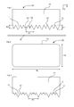
- Figure 1 depicts a blade 10 of a cutter 20 according to an embodiment of the present invention.
- the cutter 20 may be for a packaging apparatus 1.
- the cutter 20 may form a shape.
- the cutter 20 comprises at least one blade 10.
- Each blade 10 may comprise a plurality of first teeth 11 and a plurality of second teeth 12.
- the first teeth 11 may be longer than the second teeth 12 such that in use the first teeth 11 contact a surface 15 to be cut before the second teeth 12.
- the shape formed by the cutter 20 is not particularly limited.
- a shape is two dimensional. Hence a single straight line is not a shape, but an L-shape is a shape, for example.
- the cutter 20 forms a closed shape. In a closed shape, there are no gaps in the cutter 20 when viewed in plan. As depicted in Figure 2 , the cutter 20 may comprise a single blade 10. The single blade 10 may form a closed shape.
- Figure 10 depicts a plan view of a cutter 20 according to an embodiment of the invention.
- the cutter 20 comprises a blade 10 that forms a substantially closed shape.
- the shape is substantially closed because there is only a single relatively small gap 25.
- FIGs 11 and 12 each depict a plan view of a cutter 20 according to the present invention.
- the cutter 20 depicted in Figure 11 comprises two blades 10. Each blade 10 forms an L-shape, which is a shape that is not closed.
- the cutter 20 comprises two gaps 25 between the blades 10.
- the cutter 20 forms a rectangular shape, which is substantially closed because the gaps are small. In an embodiment the blades 10 may contact each other such that there is no gap 25.
- the cutter 20 depicted in Figure 12 comprises four blades 10. Each blade 10 forms a straight line, which is not a shape.
- the cutter 20 forms a rectangular shape, which is substantially closed because the gaps are small. In an embodiment the blades 10 may contact each other such that there is no gap 25.
- the cutter 20 comprises a single blade 10
- the cutter 20 may comprise more than one blade 10, as set out above.
- the blade 10 is brought into contact with a surface 15 to be cut.
- the first teeth 11 come into contact with the surface 15 before the second teeth 12.
- the first teeth 11 apply pressure to the points of contact between the first teeth 11 and the surface 15.
- the second teeth 12 come into contact with the surface 15, the second teeth apply pressure to the surface at the points of contact between the second teeth 12 and the surface 15.
- the pressure applied by the first teeth 11 is greater than the pressure applied by the second teeth 12 because the first teeth 11 are longer than the second teeth 12.
- the pressure along the cutting perimeter is non-uniform.
- the elongating stress to the surface 15 is reduced compared to a case in which uniform pressure is applied along the cutting perimeter, as with a standard serrated blade or a non-serrated blade.
- uniform pressure can be applied along the cutting perimeter if a serrated blade is used in which all of the teeth have substantially the same length.
- the present invention provides a serrated blade 10 that can cut through a surface 15 to be cut in an efficient way.
- the present invention provides a blade 10 that addresses the problem of the surface 15 stretching during the cutting operation. If the surface 15 stretches, then the surface 15 may not be completely cut, or the blade 10 may be required to move a greater distance beyond the starting line of the surface 15 (i.e. through the surface 15) so as to complete the cut.
- a die cutting operation is a cutting operation in which a blade that forms a closed shape cuts a surface 15 to be cut.
- a die cutting operation is contrasted with a straight cutting operation.
- a straight cutting operation a straight line is cut in a surface to be cut by a blade.
- stretching of the surface during the cutting operation can be effectively reduced by applying tension to the surface during the cutting operation.
- the surface to be cut is a type of plastic film
- the plastic film can be stretched out before the blade comes into contact with the plastic film. In this way, the plastic film stretches by a reduced amount during the straight cutting operation.
- first teeth 11 are interspersed with second teeth 12 of the plurality of second teeth 12. Accordingly, it is possible to avoid applying uniform pressure along the cutting perimeter of the surface 15 to be cut. This reduces elongation of the surface 15 to be cut which would otherwise hinder the cutting process.
- the serrated blade 10 may comprise at least as many second teeth 12 as first teeth 11. In this case, at least one second tooth 12 may be disposed between each pair of adjacent first teeth 11. In an embodiment, the serrated blade 10 may comprise at least as many first teeth 11 as second teeth 12. In this case, there may be at least one first tooth 11 disposed between each pair of adjacent second teeth 12. In an embodiment, the blade 10 comprises a substantially equal number of first teeth 11 as second teeth 12. In this case, the first teeth 11 and second teeth 12 may be arranged alternately along the blade 10.
- first teeth 11 are longer than the second teeth 12 by a distance within the range of from about 0.5 mm to about 1.0 mm. Accordingly, the difference in teeth length is sufficiently great that the pressure applied along the cutting perimeter is sufficiently non-uniform so as to reduce undesirable stretching of the surface 15 to be cut during the cutting operation.
- the difference in length between the teeth is sufficiently small that the blade 10 is required to move a relatively small distance relative to the surface 15 to be cut in order to perform the cutting operation. This improves the cleanness of the cut, thereby improving its aesthetic appearance. If the difference in teeth length were large, then the blade would have to move a large distance in order for the second teeth to come into contact with the partially-stretched film to perform the cutting.
- the first teeth 11 have a length of at least 3 mm. In an embodiment the first teeth 11 have a length of at most 4 mm. In an embodiment the first teeth 11 have a length of about 4 mm. In an embodiment all of the first teeth 11 have substantially the same length as each other such that in use all of the first teeth 11 contact a surface 15 to be cut at substantially the same time. However, there may be slight variations between the lengths of the first teeth 11 within manufacturing tolerances.
- a plurality of the plurality of second teeth 12 have a length of at least 2 mm, optionally at least 2.5 mm and optionally at least 3 mm. In an embodiment a plurality of the plurality of second teeth 12 have a length of at most 3.5 mm and optionally at most 3 mm. In an embodiment a plurality of the plurality of second teeth 12 have a length of about 3 mm.
- all of the second teeth 12 have substantially the same length as each other such that in use all of the second teeth 12 contact a surface 15 to be cut at substantially the same time.
- the second teeth 12 may comprise a plurality of sets of teeth having different lengths.
- first teeth 11 are longer than the second teeth 12 by a distance of at least 0.5 mm and optionally at least 0.7 mm.
- the first teeth 11 are longer than the second teeth 12 by a distance of at most 1 mm.
- first teeth 11 are longer than the second teeth 12 by a distance of about 1 mm.
- a ratio of a length of the first teeth 11 to the length of the second teeth 12 is at least 8:7 (or about 1.15 expressed fractionally). In an embodiment the ratio of the length of first teeth 11 to the length of the second teeth 12 is at most 3:2 (or about 1.50 expressed fractionally). In an embodiment the ratio of the length of the first teeth 11 to the length of the second teeth 12 is about 4:3 (or about 1.35 expressed fractionally).
- the fractions are expressed to the nearest 0.05.
- first teeth 11 are so far apart from each other that the surface 15 to be cut merely bends when contacted by the first teeth 11 but is not cut.
- This undesirable effect can be overcome by providing first teeth 11 having a very narrow angle A1 at their tip so that they can be arranged closer together. However, this makes the first teeth 11 more susceptible to breakage.
- the first teeth 11 may have penetrated the surface 15 such that they no longer apply pressure to the surface 15 when the second teeth 12 come into contact with the surface 12. In this case, the effect of applying non-uniform pressure along the surface 15 is reduced.
- each tooth is measured from the tip of the tooth to the root of the tooth.
- the length is measured in the direction in which the blade moves so as to perform the cutting operation. As shown in Figure 1 , this is the Y-direction.
- the root of the tooth is the position at which the tooth joins the base portion of the blade 10.
- the base portion of the blade is substantially solid and rectangular and is not serrated.
- the root of the tooth is level with the points 21 at which pairs of adjacent teeth separate from each other at a gap in the blade 10 in the X-direction as shown in Figure 1 .
- reference numeral 21 refers to a point at which two adjacent teeth are separated from each other. The length of each tooth is measured from point 21 to the tip of the tooth in the Y-direction.
- substantially all of the first teeth 11 and substantially all of the second teeth 12 are positioned between gaps in the X-direction that start at the same point 21 in the Y-direction. That is, all of the points 21 are at the same position in the Y-direction. However, this need not be the case. For example, the gaps that form the teeth may start at different points along the Y-direction.
- Figure 9 depicts such a structure.
- the first teeth 11 are arranged along the blade 10 at an average interval P1 within the range of from about 5 mm to about 10 mm. Accordingly, the distance between the first teeth 11 is sufficiently great so as to reduce the pressure applied on the surface 15 to be cut. This reduces the stretching of the surface 15 during the cutting operation. The distance between the first teeth is sufficiently small such that the first teeth 11 can penetrate the surface 15 to be cut so as to perform the cutting operation effectively.
- the interval at which the first teeth 11 are arranged is denoted by reference numeral P1.
- the first teeth 11 are arranged along the blade at an average interval P1 of at least 5 mm, optionally at least 7 mm and optionally at least 9 mm.
- the first teeth 11 are arranged along the blade at an average interval P1 of at most 10 mm, and optionally at most 7 mm.
- the first teeth 11 are arranged along the blade at an average interval P1 of about 6.5 mm.
- first teeth 11 and/or second teeth 12 are arranged along the blade at substantially regular intervals.
- the intervals need not be perfectly regular. For example, there may be slight variations between intervals within manufacturing tolerances.
- the intervals may be irregular. In this case, the intervals may correspond to a repeating pattern, or may be substantially random.
- the blade 10 comprises a substantially equal number of first teeth 11 and second teeth 12.
- Figure 1 depicts an embodiment in which the blade 10 comprises a substantially equal number of first teeth 11 and second teeth 12. However, this need not be the case.
- the blade 10 comprises about two times the number of second teeth 12 as first teeth 11.
- the blade 10 comprises about three times the number of second teeth 12 as first teeth 11.
- Figure 3 depicts such an embodiment.
- second teeth 12 are disposed along the blade 10 between each pair of adjacent first teeth 11.
- the ratio of first teeth to second teeth is not particularly limited. Accordingly, the ratio of first teeth 11 to second teeth 12 can be chosen so as to minimize stretching of a film to be cut during a cutting operation.
- the plurality of second teeth 12 comprises at least two sets of teeth that have different lengths such that in use the two sets of teeth contact a surface 15 to be cut at different times.
- Figure 3 depicts such an embodiment in which the plurality of second teeth 12 comprises two sets of teeth having different lengths.
- the blade 10 comprises teeth 11, 12 of three different lengths. Accordingly, during a cutting operation the first teeth 11 contact the surface 15 to be cut first. The first teeth 11 start penetrating the surface 15. Then, on a second step, the longer of the two sets of second teeth 12 continue the cutting of the surface 15. Then, on a third step, the shorter of the two sets of second teeth 12 complete the cutting of the surface 15 in an efficient way.
- the distance between the teeth of the longer set of second teeth 12 can be chosen so as to minimize pressure on the surface 15 to be cut during the second step of the cutting operation. This helps to reduce the stretching of the surface 15 during the cutting operation. In turn, this improves the quality of the cut.
- the blade 10 comprises about two times the number of the longer set of second teeth 12 as the shorter set of the second teeth 12. There may be at least one of the shorter teeth of second teeth 12 disposed between each adjacent pair of the longer set of second teeth 12. Each first tooth 11 may be positioned between a pair of the longer set of second teeth 12.
- each of the first teeth 11 forms a sharp point at its tip.
- the tip may have an angle A1, in the plane of the blade 10, within the range of from about 50° to about 60°.
- each of the second teeth 12 forms a sharp point at its tip having an angle A2, in the plane of the blade 10, within the range of from about 50° to about 60°.
- the angle is sufficiently small that the teeth 11, 12 can penetrate the surface 15 to be cut while reducing the undesirable stretching of the surface 15 during the cutting operation. Furthermore, the angle is sufficiently great the first teeth 11 can, during the penetration of the surface 15, create a slit that is sufficiently long as to aid the completion of the cutting operation during the second and optionally third cutting steps. Additionally, the first teeth 11 continue to apply pressure on the surface 15 to be cut when the second teeth 12 come into contact with the surface 15.
- the tip angle A1 of the first teeth 11 and the tip angle A2 of the second teeth 12 may be substantially equal to each other. However, this need not be the case.
- the tip angle A1 of the first teeth 11 may be about 50°.
- the tip angle A2 of the second teeth 12 may be about 50°, or may be a different angle such as 55° or 60°.
- each of the first teeth 11 and/or each of the second teeth 12 forms a substantially triangular shape.
- the triangular shape provides a sharp tip.
- other shapes of teeth are possible and the shape is not particularly limited.
- the teeth 11, 12 need not have a sharp tip.
- other shapes of teeth that are possible are a rectangle or a semi-circle.
- Figure 4 depicts a cross-section of the blade 10 across the thickness of the blade.
- the X-direction of Figure 1 corresponds to the direction into and out of the page in Figure 4 .
- the thickness T of the blade tapers towards the tips of the first teeth 11 and/or towards the tips of the second teeth 12. Accordingly, the sharpness of the blade can be improved.
- the blade 10 may have sharp singular points at which it comes into contact with a surface 15 to be cut. This helps penetration of the surface 15 by the blade 10.
- the tapering angle A3 is at least about 10°, and option ally at least about 15°. In an embodiment the tapering angle A3 is at most about 30°, and optionally at most about 20°. In an embodiment the tapering angle A3 is about 17°.
- the tapering angle A3 is sufficiently low so that the blade 10 of the cutter 20 is sharp, thereby penetrating the surface 15 more easily. Furthermore, the tapering angle A3 is sufficiently high so that the blade 10 is durable. If the tapering angle A3 is to low, then the tip of the blade 10 becomes more easily broken. This is particularly a danger because the blade 10 may come into contact with the tray 81 during a cutting operation, the tray 81 being harder than the film 82.
- the thickness T of the blade is in the range of from about 0.8 mm to about 2 mm, and preferably about 1.0 mm.
- the thickness T of the blade is measured in the base portion of the blade 10, and not in the tapering portion of the blade 10.
- Figure 5 depicts a blade according to an embodiment of the invention.
- Figure 4 and Figure 5 may depict the same blade 10 viewed from different angles.
- the hatched section of the blade 10 depicted in Figure 5 corresponds to the tapered portion of the blade 10.
- Figure 4 is a cross-section taken along line Z in Figure 5 .
- a packaging apparatus 1 comprising the cutter 20 according to an embodiment of the invention. Accordingly, the blade 10 can be used to perform clean cuts in packaging processes.
- the packaging apparatus 1 comprises an actuator 71.
- the actuator 71 is configured to move the blade 10 in a cutting operation.
- the packaging apparatus 1 is configured such that the actuator 71 moves the blade 10 by a maximum distance within the range of from about 5 mm to about 15 mm.
- the blade 10 may be moved by a sufficient distance so as to perform a complete cut of the surface 15 to be cut. Furthermore, the movement of the blade 10 relative to the surface 15 to be cut is limited such that the aesthetic appearance of the completed cut is improved. In particular, if a large relative movement between the blade 10 and the surface 15 occurs, then the cut may have an undesirable appearance.
- the packaging apparatus is configured such that the actuator 71 moves the blade 10 by a maximum distance of at least 5 mm. In an embodiment, the packaging apparatus 1 is configured such that the actuator 71 moves the blade 10 by a maximum distance of at most 15 mm.
- the actuator 71 may comprise a motor to drive the blade 10 during a cutting operation. However, the type of actuator 71 is not particularly limited.
- the packaging apparatus 1 comprises a sealer 72.
- the sealer 72 may be a heat sealer.
- the sealer 72 is configured to seal a film to a tray.
- the blade 10 can be used in the context of a packaging apparatus 1 that applies film lids to trays.
- the trays may be used to package food.
- the tray 81 may be formed of a foam material, or may be formed from a solid plastic sheet, for example.
- the film 82 is sealable, preferably heat sealable.
- the film 82 comprises a heat sealable polyolefin, preferably a polyethylene material.
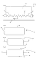
- the packaging apparatus 1 may comprise a tray lidding machine 60, as depicted in Figure 6 , for example.
- the tray lidding machine 60 comprises a support section 62 and a cut/seal section 61.
- the support section 62 is configured to support at least one tray 81.
- the support section 62 may support three or five trays 81, for example, the exact number not being particularly limited.
- the support section 62 comprises compartments configured to hold and position the tray 81 in a predefined position.
- the cut/seal section comprises the blade 10 and a sealer 72.
- a film 82 is suspended above the tray 81.
- the cut/seal section 61 is brought together with the support section 62.
- the blade 10 and sealer 72 cut and seal, respectively, the film 82 to the tray 81 to form a lid.
- Figure 7 depicts a part of a packaging apparatus 1 according to an embodiment of the invention. An exemplary operation of the apparatus depicted in Figure 7 is set out below.
- the film 82 is suspended above the tray 81.
- An actuator actuates the sealer 72 such that the sealer 72 presses the film 82 onto the tray 81. Accordingly, the film 82 forms the lid of the packaging that is to be formed.
- the actuator 71 moves the blade 10 so as to cut the film 81.
- the blade 10 is configured to cut the film 82 so as to form the desired shape of the lid of the food packaging.
- the blade 10 may form a rectangular shape.
- the rectangular shape may optionally have rounded corners.
- the blade has a width TW, in plan view, within the range of from about 10cm to about 50cm.
- the blade has a length TL, in plan view, within the range of from about 15cm to about 75cm.
- the blade may form a circular or oval shape.
- the lid may have substantially the same shape as the tray 81.
- the blade 10 can be designed to form a shape that matches the shape of the tray 81.
- the actuator 71 that actuates the sealer 72 may be the same as the actuator that actuates the blade 10. However, this need not be the case. For example, a separate actuator may be used to move each of the sealer 72 and the blade 10.
- the film 82 may be sealed to the tray 81 either before or after the film 82 is cut by the blade 10. As depicted in Figure 7 , in an embodiment the film 82 is sealed to the tray 81 before the film 82 is cut by the blade 10. As depict ed in Figure 8 , in an embodiment the film is cut by the blade 10 before the film 82 is sealed to the tray 81 by the sealer 72.
- the sealer 72 may be configured to seal the film 82 to the tray 81 by heating the film 82 to the tray 81.
- a sealer 72 is configured to heat to a temperature within the range of from about 100° Celsius to about 220° Celsius so as to seal the film 82 to the tray 81.
- the blade 10 can be used to efficiently cut a film 82 that has undergone heating. This is significant because when a film 82 is heated, it can before even more stretchable than normal. As such, a heated film 82 is more susceptible to undergo undesirable elongation and/or stretching during a cutting operation. Hence, a heated film 82 can be more difficult to cut than a non-heated film.
- the blade 10 of the present invention has been found to be able to cut thin and stretchable films even after they have undergone heating.
- the packaging apparatus 1 comprises at least one insulating plate 83 configured to insulate the blade 10 from the sealer 72.
- the insulating plate 83 reduces the heat energy absorbed by the blade 10, thereby reducing the temperature of the blade 10 in operation. This reduces the heating effect of the film 82 during the cutting operation by the blade 10.
- the blade 10 may reach a temperature within the range of about 60° Celsius to about 170° Celsius.
- the blade 10 is formed from a metal.
- the blade 10 is formed from a metal that can withstand a temperature of at least 100° Celsius.
- the metal may be stainless steel, for example. Other types of metal may also be suitable.
- the sealer 72 comprises a shape that corresponds substantially to the shape of the outline of the tray 81. Hence, as the sealer 72 presses the film 82 against the tray 81, the sealer 72 seals the film 81 to the border of the frame of the tray 81.
- the sealer 72 is attached to a frame 75 of the packaging apparatus 1 by at least one spring 84.
- the at least one spring 84 compresses.
- the blade 10 which may be connected either directly or indirectly to the same frame 75 as the sealer 72, comes into contact with the film 82 sealed on the tray 81.
- the blade 10 cuts the film 82.
- the blade 10 is connected to a frame 75 of the packaging apparatus 1 either indirectly or directly by at least one spring 85.
- the blade 10 presses the film 82 against the tray 81 and cuts the film 82.
- the tray 81 prevents further movement of the blade 10 and the at least one spring 85 compresses.
- the sealer 72 presses the cut film 82 against the tray 81 and seals it.
- seal and cut steps described for Figures 7 and 8 above may be performed by raising the support section 62 rather then by lowering the cut/seal section 61 of the packaging apparatus 1 or by a combination of both the movements.
- the blade 10 may come into contact with the tray 81 itself.
- the blade 10 should be durable so as to maintain structural integrity during contact with the tray 81.
- the first teeth 11 penetrate the film 82 before the film 82 is completely cut through. It is possible that the first teeth 11 begin to cut through the tray 81 during the cutting operation.
- the blade 10 of the present invention is particularly advantageous when used to cut thin and stretchable film 82. This may be the case when the blade 10 is used, for example, in the context of a tray lidding machine 60.
- the packaging apparatus 1 comprises a film dispenser 65 configured to dispense film 82.
- the film dispenser 65 may be configured to dispense film 82 that has a thickness of less than about 30 ⁇ m, optionally less than about 25 ⁇ m, optionally less than about 20 ⁇ m, and optionally about 15 ⁇ m or less.
- the film 82 has a Young's modulus of less than about 100,000 MPa.
- the packaging apparatus 1 is configured such that the serrated blade 10 cuts the film 82. Accordingly, the blade 10 of the present invention can be used to efficiently cut through a film 82 that is thin and/or stretchable.
- the film 82 has a Young's modulus of less than about 60,000 MPa, optionally less than about 50,000 MPa and optionally less than about 30,000 MPa. In an embodiment the film has an elastic modulus of about 60,000 MPa, about 50,000 MPa, or about 25,000 MPa. The elastic modulus is measured at a temperature of 23°C using standard techniques (ASTM D-883).
- the film 82 may have an elongation of at least 60%, and optionally at least 80%.
- the elongation corresponds to the strain of the material (expressed as a percentage of the starting length) when a force is applied to a length of the material at the time when the material breaks (ASTM D-882).
- the film 82 comprises a material that has a tensile strength of less than about 11,000 MPa, optionally less than about 9,000 MPa, and optionally about 8,500 MPa (ASTM D-882).
- Sample A is a polyethylene based barrier film that comprises polyamide, described in EP236099 .
- the polyamide gives stiffness to the film.
- Sample B described in W02011029950
- Sample C described in US5942326 , are polyethylene based materials.
- the Sample B is known to be particularly soft.
- the Sample C material is known to be particularly stretchable.
- a film 82 comprising any of these exemplary materials can be cut, providing a clean cut.
- the tests were performed using the tray lidding machine Mondini 380 in the context of sealing lids onto foam trays.
- the blade 10 of the present invention can cut these films 82 which are thin and stretchable even when the film 82 is sealed by heat to the tray 81 prior to the blade 10 cutting through the film. A cut that has a pleasing aesthetic appearance can be achieved.
Landscapes
- Engineering & Computer Science (AREA)
- Mechanical Engineering (AREA)
- Life Sciences & Earth Sciences (AREA)
- Forests & Forestry (AREA)
- Perforating, Stamping-Out Or Severing By Means Other Than Cutting (AREA)
- Nonmetal Cutting Devices (AREA)
- Auxiliary Devices For And Details Of Packaging Control (AREA)
- Package Closures (AREA)
Priority Applications (5)
| Application Number | Priority Date | Filing Date | Title |
|---|---|---|---|
| EP20110189494 EP2594496B1 (fr) | 2011-11-17 | 2011-11-17 | Appareil de conditionnement comportant un découpeur pour découper un film |
| ES11189494.5T ES2541712T3 (es) | 2011-11-17 | 2011-11-17 | Aparato de envasado que comprende un cortador para cortar una película |
| AU2012254875A AU2012254875A1 (en) | 2011-11-17 | 2012-11-14 | Cutter, packaging apparatus and method of cutting a film |
| NZ603632A NZ603632B2 (en) | 2011-11-17 | 2012-11-15 | Cutter, packaging apparatus and method of cutting a film |
| US13/679,202 US20140000217A1 (en) | 2011-11-17 | 2012-11-16 | Cutter, Packaging Apparatus and Method of Cutting a Film |
Applications Claiming Priority (1)
| Application Number | Priority Date | Filing Date | Title |
|---|---|---|---|
| EP20110189494 EP2594496B1 (fr) | 2011-11-17 | 2011-11-17 | Appareil de conditionnement comportant un découpeur pour découper un film |
Publications (2)
| Publication Number | Publication Date |
|---|---|
| EP2594496A1 true EP2594496A1 (fr) | 2013-05-22 |
| EP2594496B1 EP2594496B1 (fr) | 2015-04-08 |
Family
ID=45002739
Family Applications (1)
| Application Number | Title | Priority Date | Filing Date |
|---|---|---|---|
| EP20110189494 Not-in-force EP2594496B1 (fr) | 2011-11-17 | 2011-11-17 | Appareil de conditionnement comportant un découpeur pour découper un film |
Country Status (4)
| Country | Link |
|---|---|
| US (1) | US20140000217A1 (fr) |
| EP (1) | EP2594496B1 (fr) |
| AU (1) | AU2012254875A1 (fr) |
| ES (1) | ES2541712T3 (fr) |
Cited By (8)
| Publication number | Priority date | Publication date | Assignee | Title |
|---|---|---|---|---|
| CN103848015A (zh) * | 2014-04-01 | 2014-06-11 | 孔强光 | 一种包装机内膜切割装置 |
| JP2015078886A (ja) * | 2013-10-16 | 2015-04-23 | 日立アロカメディカル株式会社 | 試験管封止装置 |
| AT517762A1 (de) * | 2015-10-14 | 2017-04-15 | Voestalpine Prec Strip Gmbh | Schneidwerkzeug zum Trennen von Flachmaterialien |
| NL2018039B1 (nl) * | 2016-12-21 | 2018-06-28 | Cologic B V | Mes en daarvan voorziene snij-inrichting |
| WO2018133918A1 (fr) * | 2017-01-17 | 2018-07-26 | Flatev Ag | Dispositif de préparation d'aliment doté d'un couteau étagé |
| CN109573207A (zh) * | 2018-12-29 | 2019-04-05 | 天津兴雅医疗设备科技有限公司 | 一种药品包装设备的扎剪机构刀片 |
| EP3446989A3 (fr) * | 2017-05-22 | 2019-06-26 | GEA Food Solutions Germany GmbH | Machine d'emballage destinée à la fabrication d'un emballage multicouche |
| EP3885085A3 (fr) * | 2020-03-24 | 2021-12-15 | Rohrer Tools AG | Outil de poinçonnage |
Families Citing this family (8)
| Publication number | Priority date | Publication date | Assignee | Title |
|---|---|---|---|---|
| DE102010004635B4 (de) * | 2010-01-14 | 2011-09-22 | Multivac Sepp Haggenmüller Gmbh & Co. Kg | Siegelwerkzeug |
| EP2783990A1 (fr) * | 2013-03-27 | 2014-10-01 | Multivac Sepp Haggenmüller GmbH & Co. KG | Machine de verrouillage de coques et procédé |
| US20160325868A1 (en) * | 2015-05-08 | 2016-11-10 | Alkar-Rapidpak, Inc. | Contour cutting station for web packaging machine |
| US11440109B1 (en) * | 2016-12-19 | 2022-09-13 | The Steel Network, Inc. | Metal stud cutting blade and related machines and methods |
| US11472579B2 (en) | 2018-12-04 | 2022-10-18 | Gpcp Ip Holdings Llc | Film securing apparatus and method |
| GB201810694D0 (en) * | 2018-06-29 | 2018-08-15 | Randox Laboratories Ltd | Cartridge sealing apparatus |
| US12077337B2 (en) | 2018-12-04 | 2024-09-03 | Yum Connect, LLC | Systems and methods for sealing a container |
| CN110405820A (zh) * | 2019-08-09 | 2019-11-05 | 绍兴欢歌智能科技有限公司 | 一种电子雷管控制芯片分切设备 |
Citations (12)
| Publication number | Priority date | Publication date | Assignee | Title |
|---|---|---|---|---|
| BE621802A (fr) * | ||||
| GB551569A (en) * | 1941-12-12 | 1943-03-01 | Fanfold Ltd | Improvements relating to cutting devices |
| US3908342A (en) * | 1973-10-26 | 1975-09-30 | Fmc Corp | Heat sealing machine |
| GB2042962A (en) * | 1979-02-21 | 1980-10-01 | Illig Maschinenbau Adolf | Apparatus for Separating Conjoined Articles and Transporting the Articles |
| EP0236099A2 (fr) | 1986-02-28 | 1987-09-09 | W.R. Grace & Co.-Conn. | Film d'emballage barrière d'oxygène |
| DE8904789U1 (de) * | 1989-04-17 | 1989-08-10 | Steuer, Herbert, 6380 Bad Homburg | Schneidvorrichtung für Bänder an Abrollgeräten |
| US5942326A (en) | 1996-06-07 | 1999-08-24 | Cryovac, Inc. | Shrink film with good ink adhesion |
| US6382068B1 (en) * | 1997-11-03 | 2002-05-07 | Axel Balke | Strip-shaped or reciprocating knife |
| GB2462282A (en) * | 2008-07-31 | 2010-02-03 | Maxpat Trading & Marketing | Culinary utensil |
| EP2204330A1 (fr) * | 2007-10-01 | 2010-07-07 | Kureha Corporation | Bord de coupe pour conteneur d'emballage et conteneur d'emballage le comportant |
| US20110027438A1 (en) * | 2009-07-29 | 2011-02-03 | Finkowski James W | Hffs packaging method and apparatus for refrigerated dough |
| WO2011029950A1 (fr) | 2009-09-14 | 2011-03-17 | Cryovac, Inc. | Film thermorétractable étanche aux gaz |
Family Cites Families (5)
| Publication number | Priority date | Publication date | Assignee | Title |
|---|---|---|---|---|
| GB1206667A (en) * | 1968-05-15 | 1970-09-30 | Sidaplax S A | Production of packages |
| EP1340693A1 (fr) * | 2002-02-26 | 2003-09-03 | Cryovac, Inc. | Emballage à ouverture facile |
| US20080223004A1 (en) * | 2003-11-07 | 2008-09-18 | Diehl Hoyt B | Release-Coated Packaging Tooling |
| ITBO20050065A1 (it) * | 2005-02-10 | 2006-08-11 | Awax Progettazione | Macchina per il confezionamento di prodotti alimentari in vassoi chiusi superiormente a tenuta con un film termoplastico,particolarmente per produrre confezioni in atmosfera modificata e relativo procedimento di lavoro |
| ES2429421T3 (es) * | 2006-10-13 | 2013-11-14 | Cryovac, Inc. | Artículos de espuma moldeados resistentes al calor y procedimiento para su fabricación |
-
2011
- 2011-11-17 EP EP20110189494 patent/EP2594496B1/fr not_active Not-in-force
- 2011-11-17 ES ES11189494.5T patent/ES2541712T3/es active Active
-
2012
- 2012-11-14 AU AU2012254875A patent/AU2012254875A1/en not_active Abandoned
- 2012-11-16 US US13/679,202 patent/US20140000217A1/en not_active Abandoned
Patent Citations (12)
| Publication number | Priority date | Publication date | Assignee | Title |
|---|---|---|---|---|
| BE621802A (fr) * | ||||
| GB551569A (en) * | 1941-12-12 | 1943-03-01 | Fanfold Ltd | Improvements relating to cutting devices |
| US3908342A (en) * | 1973-10-26 | 1975-09-30 | Fmc Corp | Heat sealing machine |
| GB2042962A (en) * | 1979-02-21 | 1980-10-01 | Illig Maschinenbau Adolf | Apparatus for Separating Conjoined Articles and Transporting the Articles |
| EP0236099A2 (fr) | 1986-02-28 | 1987-09-09 | W.R. Grace & Co.-Conn. | Film d'emballage barrière d'oxygène |
| DE8904789U1 (de) * | 1989-04-17 | 1989-08-10 | Steuer, Herbert, 6380 Bad Homburg | Schneidvorrichtung für Bänder an Abrollgeräten |
| US5942326A (en) | 1996-06-07 | 1999-08-24 | Cryovac, Inc. | Shrink film with good ink adhesion |
| US6382068B1 (en) * | 1997-11-03 | 2002-05-07 | Axel Balke | Strip-shaped or reciprocating knife |
| EP2204330A1 (fr) * | 2007-10-01 | 2010-07-07 | Kureha Corporation | Bord de coupe pour conteneur d'emballage et conteneur d'emballage le comportant |
| GB2462282A (en) * | 2008-07-31 | 2010-02-03 | Maxpat Trading & Marketing | Culinary utensil |
| US20110027438A1 (en) * | 2009-07-29 | 2011-02-03 | Finkowski James W | Hffs packaging method and apparatus for refrigerated dough |
| WO2011029950A1 (fr) | 2009-09-14 | 2011-03-17 | Cryovac, Inc. | Film thermorétractable étanche aux gaz |
Cited By (10)
| Publication number | Priority date | Publication date | Assignee | Title |
|---|---|---|---|---|
| JP2015078886A (ja) * | 2013-10-16 | 2015-04-23 | 日立アロカメディカル株式会社 | 試験管封止装置 |
| CN103848015A (zh) * | 2014-04-01 | 2014-06-11 | 孔强光 | 一种包装机内膜切割装置 |
| AT517762A1 (de) * | 2015-10-14 | 2017-04-15 | Voestalpine Prec Strip Gmbh | Schneidwerkzeug zum Trennen von Flachmaterialien |
| EP3168016A1 (fr) * | 2015-10-14 | 2017-05-17 | voestalpine Precision Strip GmbH | Outil de coupe destine a separer des materiaux plats |
| NL2018039B1 (nl) * | 2016-12-21 | 2018-06-28 | Cologic B V | Mes en daarvan voorziene snij-inrichting |
| WO2018117822A1 (fr) * | 2016-12-21 | 2018-06-28 | Cologic B.V. | Lame et dispositif de coupe équipé de ladite lame |
| WO2018133918A1 (fr) * | 2017-01-17 | 2018-07-26 | Flatev Ag | Dispositif de préparation d'aliment doté d'un couteau étagé |
| EP3446989A3 (fr) * | 2017-05-22 | 2019-06-26 | GEA Food Solutions Germany GmbH | Machine d'emballage destinée à la fabrication d'un emballage multicouche |
| CN109573207A (zh) * | 2018-12-29 | 2019-04-05 | 天津兴雅医疗设备科技有限公司 | 一种药品包装设备的扎剪机构刀片 |
| EP3885085A3 (fr) * | 2020-03-24 | 2021-12-15 | Rohrer Tools AG | Outil de poinçonnage |
Also Published As
| Publication number | Publication date |
|---|---|
| EP2594496B1 (fr) | 2015-04-08 |
| US20140000217A1 (en) | 2014-01-02 |
| AU2012254875A1 (en) | 2013-06-06 |
| NZ603632A (en) | 2014-06-27 |
| ES2541712T3 (es) | 2015-07-23 |
Similar Documents
| Publication | Publication Date | Title |
|---|---|---|
| EP2594496B1 (fr) | Appareil de conditionnement comportant un découpeur pour découper un film | |
| EP1935789B1 (fr) | Procédé et installation pour emballer des objets d'une façon étanche au gaz | |
| EP1747995B1 (fr) | Procédé et appareil pour emballer des articles dans un film à pelliplacage, étanche au gaz | |
| AU2016315780B2 (en) | Formed thermoplastic article having smooth edges | |
| DE102011115881B4 (de) | Tiefziehverpackungsmaschine mit einseitiger Folienvorschubeinrichtung | |
| US20130276604A1 (en) | Methods and equipment for cutting food products | |
| EP2722281B1 (fr) | Procédé d'emballage d'objets de manière étanche au gaz à l'aide d'un film emboutissable appliqué contre les objets, sous l'application d'un vide | |
| KR101772741B1 (ko) | 초음파 용접 방법에 의해 얇은 합성수지 박막으로 튜브형 백을 제조하는 방법 및 장치 | |
| TW201540680A (zh) | 裂斷方法及裂斷裝置 | |
| JP2014012536A (ja) | ブリスターパック、ブリスターパック製造装置及びブリスターパックの製造方法 | |
| NZ603632B2 (en) | Cutter, packaging apparatus and method of cutting a film | |
| US10071495B2 (en) | Device and method for cutting plastic material, in particular a laminated glazing element | |
| EP4168313A1 (fr) | Machine d'emballage comprenant un outil de découpage | |
| EP3319881B1 (fr) | Machine d'emballage à évacuation de rognures | |
| DE60216965T2 (de) | Verfahren zum schneiden eines poly(vinylalkohol)glieds | |
| EP2783990A1 (fr) | Machine de verrouillage de coques et procédé | |
| DE10208997B4 (de) | Verfahren und Vorrichtung zum Stanzen von versiegelten becherartigen Behältern | |
| US20150210021A1 (en) | Deep-drawing packaging machine comprising an ultrasonic device | |
| CN109956661A (zh) | 贴合基板的刻划方法及刻划装置 | |
| EP4656531A1 (fr) | Procédé et dispositif pour appliquer un film de couverture sur une barquette d'emballage | |
| CN219380772U (zh) | 一种珍珠棉分切机构 | |
| CN105857774A (zh) | 一种包装机冲切装置 | |
| US20110268928A1 (en) | Method of sealing hollow multi-walled panels and panels thus obtained | |
| JP3189706U (ja) | 打抜き型 | |
| BG1874U1 (bg) | Машина за кантоване на сепаратори от полипропиленово велпапе |
Legal Events
| Date | Code | Title | Description |
|---|---|---|---|
| PUAI | Public reference made under article 153(3) epc to a published international application that has entered the european phase |
Free format text: ORIGINAL CODE: 0009012 |
|
| AK | Designated contracting states |
Kind code of ref document: A1 Designated state(s): AL AT BE BG CH CY CZ DE DK EE ES FI FR GB GR HR HU IE IS IT LI LT LU LV MC MK MT NL NO PL PT RO RS SE SI SK SM TR |
|
| AX | Request for extension of the european patent |
Extension state: BA ME |
|
| 17P | Request for examination filed |
Effective date: 20131122 |
|
| RBV | Designated contracting states (corrected) |
Designated state(s): AL AT BE BG CH CY CZ DE DK EE ES FI FR GB GR HR HU IE IS IT LI LT LU LV MC MK MT NL NO PL PT RO RS SE SI SK SM TR |
|
| 17Q | First examination report despatched |
Effective date: 20131219 |
|
| GRAP | Despatch of communication of intention to grant a patent |
Free format text: ORIGINAL CODE: EPIDOSNIGR1 |
|
| INTG | Intention to grant announced |
Effective date: 20141106 |
|
| GRAS | Grant fee paid |
Free format text: ORIGINAL CODE: EPIDOSNIGR3 |
|
| GRAA | (expected) grant |
Free format text: ORIGINAL CODE: 0009210 |
|
| AK | Designated contracting states |
Kind code of ref document: B1 Designated state(s): AL AT BE BG CH CY CZ DE DK EE ES FI FR GB GR HR HU IE IS IT LI LT LU LV MC MK MT NL NO PL PT RO RS SE SI SK SM TR |
|
| REG | Reference to a national code |
Ref country code: GB Ref legal event code: FG4D |
|
| REG | Reference to a national code |
Ref country code: CH Ref legal event code: EP |
|
| REG | Reference to a national code |
Ref country code: IE Ref legal event code: FG4D |
|
| REG | Reference to a national code |
Ref country code: AT Ref legal event code: REF Ref document number: 720363 Country of ref document: AT Kind code of ref document: T Effective date: 20150515 |
|
| REG | Reference to a national code |
Ref country code: DE Ref legal event code: R096 Ref document number: 602011015397 Country of ref document: DE Effective date: 20150521 |
|
| REG | Reference to a national code |
Ref country code: ES Ref legal event code: FG2A Ref document number: 2541712 Country of ref document: ES Kind code of ref document: T3 Effective date: 20150723 |
|
| REG | Reference to a national code |
Ref country code: AT Ref legal event code: MK05 Ref document number: 720363 Country of ref document: AT Kind code of ref document: T Effective date: 20150408 |
|
| REG | Reference to a national code |
Ref country code: NL Ref legal event code: VDEP Effective date: 20150408 |
|
| REG | Reference to a national code |
Ref country code: LT Ref legal event code: MG4D |
|
| PG25 | Lapsed in a contracting state [announced via postgrant information from national office to epo] |
Ref country code: NL Free format text: LAPSE BECAUSE OF FAILURE TO SUBMIT A TRANSLATION OF THE DESCRIPTION OR TO PAY THE FEE WITHIN THE PRESCRIBED TIME-LIMIT Effective date: 20150408 |
|
| PG25 | Lapsed in a contracting state [announced via postgrant information from national office to epo] |
Ref country code: HR Free format text: LAPSE BECAUSE OF FAILURE TO SUBMIT A TRANSLATION OF THE DESCRIPTION OR TO PAY THE FEE WITHIN THE PRESCRIBED TIME-LIMIT Effective date: 20150408 Ref country code: PT Free format text: LAPSE BECAUSE OF FAILURE TO SUBMIT A TRANSLATION OF THE DESCRIPTION OR TO PAY THE FEE WITHIN THE PRESCRIBED TIME-LIMIT Effective date: 20150810 Ref country code: FI Free format text: LAPSE BECAUSE OF FAILURE TO SUBMIT A TRANSLATION OF THE DESCRIPTION OR TO PAY THE FEE WITHIN THE PRESCRIBED TIME-LIMIT Effective date: 20150408 Ref country code: NO Free format text: LAPSE BECAUSE OF FAILURE TO SUBMIT A TRANSLATION OF THE DESCRIPTION OR TO PAY THE FEE WITHIN THE PRESCRIBED TIME-LIMIT Effective date: 20150708 Ref country code: LT Free format text: LAPSE BECAUSE OF FAILURE TO SUBMIT A TRANSLATION OF THE DESCRIPTION OR TO PAY THE FEE WITHIN THE PRESCRIBED TIME-LIMIT Effective date: 20150408 |
|
| PG25 | Lapsed in a contracting state [announced via postgrant information from national office to epo] |
Ref country code: AT Free format text: LAPSE BECAUSE OF FAILURE TO SUBMIT A TRANSLATION OF THE DESCRIPTION OR TO PAY THE FEE WITHIN THE PRESCRIBED TIME-LIMIT Effective date: 20150408 Ref country code: LV Free format text: LAPSE BECAUSE OF FAILURE TO SUBMIT A TRANSLATION OF THE DESCRIPTION OR TO PAY THE FEE WITHIN THE PRESCRIBED TIME-LIMIT Effective date: 20150408 Ref country code: IS Free format text: LAPSE BECAUSE OF FAILURE TO SUBMIT A TRANSLATION OF THE DESCRIPTION OR TO PAY THE FEE WITHIN THE PRESCRIBED TIME-LIMIT Effective date: 20150808 Ref country code: GR Free format text: LAPSE BECAUSE OF FAILURE TO SUBMIT A TRANSLATION OF THE DESCRIPTION OR TO PAY THE FEE WITHIN THE PRESCRIBED TIME-LIMIT Effective date: 20150709 Ref country code: RS Free format text: LAPSE BECAUSE OF FAILURE TO SUBMIT A TRANSLATION OF THE DESCRIPTION OR TO PAY THE FEE WITHIN THE PRESCRIBED TIME-LIMIT Effective date: 20150408 |
|
| REG | Reference to a national code |
Ref country code: DE Ref legal event code: R097 Ref document number: 602011015397 Country of ref document: DE |
|
| PG25 | Lapsed in a contracting state [announced via postgrant information from national office to epo] |
Ref country code: EE Free format text: LAPSE BECAUSE OF FAILURE TO SUBMIT A TRANSLATION OF THE DESCRIPTION OR TO PAY THE FEE WITHIN THE PRESCRIBED TIME-LIMIT Effective date: 20150408 Ref country code: DK Free format text: LAPSE BECAUSE OF FAILURE TO SUBMIT A TRANSLATION OF THE DESCRIPTION OR TO PAY THE FEE WITHIN THE PRESCRIBED TIME-LIMIT Effective date: 20150408 |
|
| PLBE | No opposition filed within time limit |
Free format text: ORIGINAL CODE: 0009261 |
|
| STAA | Information on the status of an ep patent application or granted ep patent |
Free format text: STATUS: NO OPPOSITION FILED WITHIN TIME LIMIT |
|
| PG25 | Lapsed in a contracting state [announced via postgrant information from national office to epo] |
Ref country code: SK Free format text: LAPSE BECAUSE OF FAILURE TO SUBMIT A TRANSLATION OF THE DESCRIPTION OR TO PAY THE FEE WITHIN THE PRESCRIBED TIME-LIMIT Effective date: 20150408 Ref country code: PL Free format text: LAPSE BECAUSE OF FAILURE TO SUBMIT A TRANSLATION OF THE DESCRIPTION OR TO PAY THE FEE WITHIN THE PRESCRIBED TIME-LIMIT Effective date: 20150408 Ref country code: RO Free format text: LAPSE BECAUSE OF NON-PAYMENT OF DUE FEES Effective date: 20150408 Ref country code: CZ Free format text: LAPSE BECAUSE OF FAILURE TO SUBMIT A TRANSLATION OF THE DESCRIPTION OR TO PAY THE FEE WITHIN THE PRESCRIBED TIME-LIMIT Effective date: 20150408 |
|
| 26N | No opposition filed |
Effective date: 20160111 |
|
| PG25 | Lapsed in a contracting state [announced via postgrant information from national office to epo] |
Ref country code: SI Free format text: LAPSE BECAUSE OF FAILURE TO SUBMIT A TRANSLATION OF THE DESCRIPTION OR TO PAY THE FEE WITHIN THE PRESCRIBED TIME-LIMIT Effective date: 20150408 |
|
| REG | Reference to a national code |
Ref country code: DE Ref legal event code: R119 Ref document number: 602011015397 Country of ref document: DE |
|
| PG25 | Lapsed in a contracting state [announced via postgrant information from national office to epo] |
Ref country code: LU Free format text: LAPSE BECAUSE OF FAILURE TO SUBMIT A TRANSLATION OF THE DESCRIPTION OR TO PAY THE FEE WITHIN THE PRESCRIBED TIME-LIMIT Effective date: 20151117 Ref country code: MC Free format text: LAPSE BECAUSE OF FAILURE TO SUBMIT A TRANSLATION OF THE DESCRIPTION OR TO PAY THE FEE WITHIN THE PRESCRIBED TIME-LIMIT Effective date: 20150408 |
|
| REG | Reference to a national code |
Ref country code: CH Ref legal event code: PL |
|
| GBPC | Gb: european patent ceased through non-payment of renewal fee |
Effective date: 20151117 |
|
| PG25 | Lapsed in a contracting state [announced via postgrant information from national office to epo] |
Ref country code: LI Free format text: LAPSE BECAUSE OF NON-PAYMENT OF DUE FEES Effective date: 20151130 Ref country code: CH Free format text: LAPSE BECAUSE OF NON-PAYMENT OF DUE FEES Effective date: 20151130 |
|
| REG | Reference to a national code |
Ref country code: IE Ref legal event code: MM4A |
|
| REG | Reference to a national code |
Ref country code: FR Ref legal event code: ST Effective date: 20160729 |
|
| PG25 | Lapsed in a contracting state [announced via postgrant information from national office to epo] |
Ref country code: BE Free format text: LAPSE BECAUSE OF FAILURE TO SUBMIT A TRANSLATION OF THE DESCRIPTION OR TO PAY THE FEE WITHIN THE PRESCRIBED TIME-LIMIT Effective date: 20150408 |
|
| PG25 | Lapsed in a contracting state [announced via postgrant information from national office to epo] |
Ref country code: IE Free format text: LAPSE BECAUSE OF NON-PAYMENT OF DUE FEES Effective date: 20151117 Ref country code: GB Free format text: LAPSE BECAUSE OF NON-PAYMENT OF DUE FEES Effective date: 20151117 Ref country code: DE Free format text: LAPSE BECAUSE OF NON-PAYMENT OF DUE FEES Effective date: 20160601 |
|
| PG25 | Lapsed in a contracting state [announced via postgrant information from national office to epo] |
Ref country code: FR Free format text: LAPSE BECAUSE OF NON-PAYMENT OF DUE FEES Effective date: 20151130 |
|
| REG | Reference to a national code |
Ref country code: ES Ref legal event code: FD2A Effective date: 20161227 |
|
| PG25 | Lapsed in a contracting state [announced via postgrant information from national office to epo] |
Ref country code: IT Free format text: LAPSE BECAUSE OF NON-PAYMENT OF DUE FEES Effective date: 20151117 Ref country code: ES Free format text: LAPSE BECAUSE OF NON-PAYMENT OF DUE FEES Effective date: 20151118 |
|
| PG25 | Lapsed in a contracting state [announced via postgrant information from national office to epo] |
Ref country code: BG Free format text: LAPSE BECAUSE OF FAILURE TO SUBMIT A TRANSLATION OF THE DESCRIPTION OR TO PAY THE FEE WITHIN THE PRESCRIBED TIME-LIMIT Effective date: 20150408 Ref country code: HU Free format text: LAPSE BECAUSE OF FAILURE TO SUBMIT A TRANSLATION OF THE DESCRIPTION OR TO PAY THE FEE WITHIN THE PRESCRIBED TIME-LIMIT; INVALID AB INITIO Effective date: 20111117 Ref country code: SM Free format text: LAPSE BECAUSE OF FAILURE TO SUBMIT A TRANSLATION OF THE DESCRIPTION OR TO PAY THE FEE WITHIN THE PRESCRIBED TIME-LIMIT Effective date: 20150408 |
|
| PG25 | Lapsed in a contracting state [announced via postgrant information from national office to epo] |
Ref country code: CY Free format text: LAPSE BECAUSE OF FAILURE TO SUBMIT A TRANSLATION OF THE DESCRIPTION OR TO PAY THE FEE WITHIN THE PRESCRIBED TIME-LIMIT Effective date: 20150408 Ref country code: SE Free format text: LAPSE BECAUSE OF FAILURE TO SUBMIT A TRANSLATION OF THE DESCRIPTION OR TO PAY THE FEE WITHIN THE PRESCRIBED TIME-LIMIT Effective date: 20150408 |
|
| PG25 | Lapsed in a contracting state [announced via postgrant information from national office to epo] |
Ref country code: MT Free format text: LAPSE BECAUSE OF FAILURE TO SUBMIT A TRANSLATION OF THE DESCRIPTION OR TO PAY THE FEE WITHIN THE PRESCRIBED TIME-LIMIT Effective date: 20150408 |
|
| PG25 | Lapsed in a contracting state [announced via postgrant information from national office to epo] |
Ref country code: TR Free format text: LAPSE BECAUSE OF FAILURE TO SUBMIT A TRANSLATION OF THE DESCRIPTION OR TO PAY THE FEE WITHIN THE PRESCRIBED TIME-LIMIT Effective date: 20150408 Ref country code: MK Free format text: LAPSE BECAUSE OF FAILURE TO SUBMIT A TRANSLATION OF THE DESCRIPTION OR TO PAY THE FEE WITHIN THE PRESCRIBED TIME-LIMIT Effective date: 20150408 |
|
| PG25 | Lapsed in a contracting state [announced via postgrant information from national office to epo] |
Ref country code: AL Free format text: LAPSE BECAUSE OF FAILURE TO SUBMIT A TRANSLATION OF THE DESCRIPTION OR TO PAY THE FEE WITHIN THE PRESCRIBED TIME-LIMIT Effective date: 20150408 |