EP2594711A2 - Dispositif de fermeture électromécanique avec une installation de fermeture rapide - Google Patents
Dispositif de fermeture électromécanique avec une installation de fermeture rapide Download PDFInfo
- Publication number
- EP2594711A2 EP2594711A2 EP12192215.7A EP12192215A EP2594711A2 EP 2594711 A2 EP2594711 A2 EP 2594711A2 EP 12192215 A EP12192215 A EP 12192215A EP 2594711 A2 EP2594711 A2 EP 2594711A2
- Authority
- EP
- European Patent Office
- Prior art keywords
- sprocket
- closure device
- drive
- lock bolt
- unit
- Prior art date
- Legal status (The legal status is an assumption and is not a legal conclusion. Google has not performed a legal analysis and makes no representation as to the accuracy of the status listed.)
- Granted
Links
Images

Classifications
-
- E—FIXED CONSTRUCTIONS
- E05—LOCKS; KEYS; WINDOW OR DOOR FITTINGS; SAFES
- E05B—LOCKS; ACCESSORIES THEREFOR; HANDCUFFS
- E05B47/00—Operating or controlling locks or other fastening devices by electric or magnetic means
- E05B47/0001—Operating or controlling locks or other fastening devices by electric or magnetic means with electric actuators; Constructional features thereof
- E05B47/0012—Operating or controlling locks or other fastening devices by electric or magnetic means with electric actuators; Constructional features thereof with rotary electromotors
-
- E—FIXED CONSTRUCTIONS
- E05—LOCKS; KEYS; WINDOW OR DOOR FITTINGS; SAFES
- E05B—LOCKS; ACCESSORIES THEREFOR; HANDCUFFS
- E05B15/00—Other details of locks; Parts for engagement by bolts of fastening devices
- E05B15/004—Lost motion connections
-
- E—FIXED CONSTRUCTIONS
- E05—LOCKS; KEYS; WINDOW OR DOOR FITTINGS; SAFES
- E05B—LOCKS; ACCESSORIES THEREFOR; HANDCUFFS
- E05B47/00—Operating or controlling locks or other fastening devices by electric or magnetic means
- E05B47/02—Movement of the bolt by electromagnetic means; Adaptation of locks, latches, or parts thereof, for movement of the bolt by electromagnetic means
- E05B47/026—Movement of the bolt by electromagnetic means; Adaptation of locks, latches, or parts thereof, for movement of the bolt by electromagnetic means the bolt moving rectilinearly
-
- E—FIXED CONSTRUCTIONS
- E05—LOCKS; KEYS; WINDOW OR DOOR FITTINGS; SAFES
- E05B—LOCKS; ACCESSORIES THEREFOR; HANDCUFFS
- E05B15/00—Other details of locks; Parts for engagement by bolts of fastening devices
- E05B15/04—Spring arrangements in locks
- E05B2015/0448—Units of springs; Two or more springs working together
-
- E—FIXED CONSTRUCTIONS
- E05—LOCKS; KEYS; WINDOW OR DOOR FITTINGS; SAFES
- E05B—LOCKS; ACCESSORIES THEREFOR; HANDCUFFS
- E05B47/00—Operating or controlling locks or other fastening devices by electric or magnetic means
- E05B47/0001—Operating or controlling locks or other fastening devices by electric or magnetic means with electric actuators; Constructional features thereof
- E05B2047/0014—Constructional features of actuators or power transmissions therefor
- E05B2047/0018—Details of actuator transmissions
- E05B2047/002—Geared transmissions
-
- E—FIXED CONSTRUCTIONS
- E05—LOCKS; KEYS; WINDOW OR DOOR FITTINGS; SAFES
- E05B—LOCKS; ACCESSORIES THEREFOR; HANDCUFFS
- E05B47/00—Operating or controlling locks or other fastening devices by electric or magnetic means
- E05B2047/0048—Circuits, feeding, monitoring
- E05B2047/0067—Monitoring
- E05B2047/0069—Monitoring bolt position
-
- E—FIXED CONSTRUCTIONS
- E05—LOCKS; KEYS; WINDOW OR DOOR FITTINGS; SAFES
- E05B—LOCKS; ACCESSORIES THEREFOR; HANDCUFFS
- E05B47/00—Operating or controlling locks or other fastening devices by electric or magnetic means
- E05B47/06—Controlling mechanically-operated bolts by electro-magnetically-operated detents
- E05B47/0607—Controlling mechanically-operated bolts by electro-magnetically-operated detents the detent moving pivotally or rotatively
Definitions
- the invention relates to an electromechanical closure device with a lock unit comprising at least one displaceable and vorspannbares lock bolt element comprising a drive unit comprising a rotatable drive element having a drive motor, and with a gear unit for transferring a drive motor side rotary drive movement in a lock bolt elements side translational driven movement solved in which a toothed gear member of the gear unit on the one hand with the rotatable drive element of the drive motor meshing and on the other hand is arranged operatively connected by means of a Hebelarmelements with the movable lock bolt element.
- a generic closure device is with that in the patent DE 44 07 912 C2 shown electromechanical lock known.
- the electromechanical lock shown there by way of example has a lock bolt which can be displaced by means of a drive motor between a closed position and an open position or vice versa.
- the lock bolt is connected via a thrust piece and a crank pin with a worm wheel of a screw of the drive motor.
- the lock bolt can be translationally moved to the closed position or into the open position when the worm of the drive motor rotates.
- an electromechanical closure device having a lock unit comprising at least one displaceable and prestressable lock bolt element, comprising a drive unit comprising a drive element having a rotatable drive element, and a transmission unit for transferring a drive motor side rotary drive movement into a lock-bolt-element-side translational output drive, in which a toothed gear member of the gear unit is meshed with the rotatable drive element of the drive motor and on the other hand operatively connected by means of a Hebelarmelements with the displaceable lock element, wherein the toothed gear member a sprocket element with a sprocket element and a relation to the sprocket movable driving element with a freewheeling section for engaging therein of the freewheeling sprocket element, wherein the rotatable drive element with the sprocket element and the lever arm element is arranged operatively connected to the driver element.
- lever arm element operatively connected to the driver element can perform a translatory output motion due to the existing freewheeling section on this driver element, without the spider element of the toothed transmission element being in engagement with the rotatable drive element having to be moved.
- the lock bolt element can be displaced into its closed position, bypassing the drive motor.
- Such a spring preload with respect to the lock bolt element can be achieved in a structurally particularly advantageous manner if the lock unit comprises a spring-biased securing element for locking the displaceable lock bolt element in the closed position.
- the lock bolt element can ideally be spring-biased if it is moved by motor to the open position, so that a sufficiently high amount of energy is stored to allow the lock bolt element to bypass the drive motor and return to the closed position. This can be done when the driver element rotates in the context of its freewheeling portion relative to the sprocket element until the driver element abuts against the sprocket pin element.
- the gear unit can be realized in an exceptionally simple manner if at least the toothed gear element and the lever arm element configure a crank drive for translational displacement of the displaceable lock bolt element, by means of which the displaceable lock bolt element can be displaced even on drive-side blocking of the toothed gear element.
- a defined interaction between the sprocket element and the entrainment element can be provided structurally simple if the entrainment element has a contact surface for the sprocket element, the entrainment element following a rotational movement of the sprocket element, after the sprocket element has started after passing through the freewheeling section to the contact surface of the driver element.
- a sufficiently large rotational potential of the driver element relative to the sprocket element in order in particular to be able to achieve a sufficiently long displacement path of the lock bolt element can be provided if the freewheeling section is more than 90 °, preferably more than 180 °, of the driver element circumference.
- the length of the freewheeling section on the circumference of the driver element can advantageously be selected specifically to the desired or required displacement path of the lock bolt element.
- a quick closing can structurally be further promoted if the driver element has a bearing pin element for rotatably supporting the lever arm element, wherein the bearing pin element is arranged approximately in the middle of the freewheel portion on the circumferential side of the catch element opposite the freewheel section.
- the gear unit can be made particularly flat with respect to its overall height.
- the present toothed transmission member is particularly compact, when the sprocket element and the driver element have a common axis of rotation.
- the sprocket element and the driver element are each ideally rotatably mounted on a common bearing pin.
- the driver element can be stored when the ring gear member cumulatively on the top side has a bearing shell means for directly supporting the driver element.
- the drive unit can cooperate well with the toothed transmission element in a confined space when the rotatable drive element comprises a threaded screw element which meshes with the toothed rim element.
- the electromechanical locking device 1 also has a light barrier device, by means of which different positions of the locking bolt element can be detected.
- the light barrier device can comprise more than one light barrier element, by means of which data for a corresponding control device can be determined, which can advantageously also be used for activating or deactivating the drive unit.
- the electromechanical closure device has an emergency closing device, which comprises means for detecting an undervoltage supply and a capacitor element for temporarily storing electrical energy for temporarily driving the drive motor.
- the emergency closing device comprises a spring device by means of which the lock bolt element can be displaced into the closed position
- the lock unit can advantageously close independently without engine power and secure the electromechanical locking device over it.
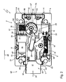
- the electromechanical lock device 1 shown by way of example is an electromechanical lock 2 for a safe 3.
- the electromechanical lock 2 comprises a two-part housing 4 with a cover part 5 and a bottom part 6, in which a lock unit 7 is accommodated.
- the cover part 5 and the bottom part 6 are screwed together by means of a plurality of housing screws 8.
- the lock unit 7 essentially comprises a lock bolt element 11 pretensioned by longer coil springs 9 and 10 and a securing element 13 prestressed by a shorter spiral spring 12, which is mounted rotatably on the lock bolt element 11 and secured thereto by a securing screw 14.
- the locking bolt element 11 can in this case in a conventional manner as Schrägliegelelement (not shown here) be executed.
- the electromechanical closure device 1 has a drive unit 15 with an electric drive motor 16 and a rotatable drive element 17, which is configured as a threaded screw element 18.
- the rotatable drive element 17 is fastened in a form-fitting manner on a rotation shaft 19 of the drive motor 16 and can thus execute at least one rotary drive movement 20 in a first direction.
- the electromechanical closure device 1 has a gear unit 25, which in the simplest case comprises a toothed gear member 26 and a lever arm member 27, wherein the toothed gear member 26 meshes with the rotatable drive member 17 of the drive motor 16 and with the threaded screw member 18 on the one hand and with the lever arm 27 is rotatably connected.
- a gear unit 25 which in the simplest case comprises a toothed gear member 26 and a lever arm member 27, wherein the toothed gear member 26 meshes with the rotatable drive member 17 of the drive motor 16 and with the threaded screw member 18 on the one hand and with the lever arm 27 is rotatably connected.
- the toothed gear member 26 and the lever arm member 27 in this case form a crank mechanism 28, by means of which the rotary drive movement 20 of the threaded screw element 18 can be converted into a translational output movement 29.
- the electromechanical closure device 1 has a quick-release device, which is embodied in particular by the construction of the toothed gear member 26.
- the toothed gear member 26 is composed of a sprocket element 30 and a driver element 31 rotatable for this purpose. Both parts 30 and 31 are mounted on a common pivot pin 32 and thus have a common axis of rotation 33, about which they can be rotated at least in the direction of rotation 34, as will be described later in more detail.
- the common axis of rotation 33 is formulated by a link device 35, which is inserted into the bottom part 6. By means of the link device 35, components of the lock unit 7, the drive unit 15 and the gear unit 25 are arranged and held within the housing 4, among other things.
- the drive motor 16 is screwed by means of hexagon socket screws 36 to a flange 37 of the link device 35.
- the two longer coil springs 9 and 10 are mounted on a wall element portion 38 of the link device 35, while they are mounted on the other side 39 on the lock bolt element 11.
- the shorter spiral spring 12 is hooked on the one hand to a bolt element 40 of the securing element 13 and on the other hand to a hook element 41. Feeding is the gate device 35 on the bottom part 6 by means of a pair of screws 42nd
- the driver element 31 is placed on the upper side of the sprocket element 30 and also mounted in a bearing shell device 45 directly to the sprocket element 30, wherein the driver element 31 and the sprocket member 30 are held to each other with a bearing screw 46 on the pivot pin 32.
- the entrainment element 31 comprises on the circumference a radially open freewheeling section 50, with respect to the rotation axis 33, in which a toothed spur element 51 engages, so that the latter 51 is placed in the freewheeling section 50 so as to be freely displaceable with respect to the entrainment element 31.
- the freewheeling section 50 is radially open, as a result of which assembly can be carried out particularly easily.
- the driver element 31 also has two contact surfaces 52 and 53, against which the sprocket element 51 can start, wherein the driver element 31 can then be entrained by the sprocket element 51 or rotated about the axis of rotation 33.
- the driver element 31 also has a bearing pin element 54 for rotatably supporting the lever arm element 27, the bearing pin element 54 being arranged approximately in the middle of the freewheeling section 50 on the peripheral side 55 of the driver element 31 opposite the freewheeling section 50.
- the bearing pin element 54 is pressed in this embodiment in a receiving opening 56 of the driver 31.
- the lever arm member 27 is thus rotatably supported on the cam member 31 on the one hand on the bearing pin member 54. On the other hand, it is in a slot 57 of the movable Lock bolt element 11 mounted, wherein the displaceable lock bolt element 11 has a sliding pin 58 on the underside, which engages in the slot 57.
- the electromechanical closure device 1 according to the invention is operated even more advantageously according to the following functional description.
- the closed state see FIG. 2
- the lock bolt element 11 extended out of the housing 4 is in a closed position 60.
- the threaded screw element 18 rotates clockwise in accordance with the rotary drive movement 20. Due to the worm drive the ring gear member 30 of the toothed gear member 26 rotates in the direction of rotation 34 also in a clockwise direction. In this case, the sprocket pin member 51 moves in the direction of the second abutment surface 53. If the sprocket member 51 abuts the second abutment surface 53, the rotational movement 34 of the sprocket member 30 transmits to the driver 31.
- the securing element 27 unlocks once the lock unit 7 by the locking lug 62 slides out of the locking groove 63 according to the pivoting movement 64 out.
- the toothed gear member 26 facing the end of the slot 57 is reached and the force of the drive motor 16 is transmitted by means of the lever arm member 27 directly form-fitting manner on the locking bolt member 11.
- this 11 moves against the spring force of the two longer coil springs 9 and 10 in the direction open 65 lock position (not shown here), in which the locking latch member 11 is displaced into the housing 4 inside. If the lock unit 7 is completely opened, this is done by a light barrier device 66 (see FIG. 2 ) and the drive motor 16 is stopped.
- the lock bolt element 11 can also be displaced into the closed position 60 by means of engine power. This may be necessary, for example, if about halfway the locking latch member 11 of the translational output movement 29 counteracts a force greater than the spring forces of the two coil springs 9 and 10 in the closed position 60, due to which the locking latch member 60 stops for the time being before the closed position 60.
- the drive unit 15 is activated and the drive motor 16, the threaded screw element 18 rotate in accordance with the rotational drive movement 20 and also the ring gear member 30 rotates according to the direction of rotation 34 on.
- an exceptionally advantageous emergency closing device can be provided.
- an electronic device 68 assigned to the electromechanical closure device 1 which comprises an undervoltage detection device 69 of a power supply and a buffer capacitor device 70 which stores sufficient electrical energy for closing the lock unit 7.
- the lock unit 7 remains in its open state until it is closed again by an operator or the power fails.
- the undervoltage detection device 69 which forwards a switching pulse to the drive unit 15.
- the drive motor 16 rotates advantageously at least so far that the lever arm member 27 and the bearing pin member 54 can drive over the reversal point 67.
- the driver element 31 can rotate by its free bearing relative to the sprocket element 30.
- the biased coil springs 9 and 10 act on the locking latch member 11 in the direction of the closed position 60, the spring forces, as previously described. These cause the locking latch member 11 can snap directly into the closed position 60.
- the electromechanical closure device 1 was thus advantageously closed reliably even during a power failure, whereby an extremely advantageous emergency closure is realized.
Landscapes
- Physics & Mathematics (AREA)
- Electromagnetism (AREA)
- Lock And Its Accessories (AREA)
Applications Claiming Priority (1)
| Application Number | Priority Date | Filing Date | Title |
|---|---|---|---|
| DE201110055421 DE102011055421B4 (de) | 2011-11-16 | 2011-11-16 | Elektromechanische Verschlussvorrichtung mit einer Schnellverschlusseinrichtung |
Publications (3)
| Publication Number | Publication Date |
|---|---|
| EP2594711A2 true EP2594711A2 (fr) | 2013-05-22 |
| EP2594711A3 EP2594711A3 (fr) | 2014-07-23 |
| EP2594711B1 EP2594711B1 (fr) | 2017-03-01 |
Family
ID=47227543
Family Applications (1)
| Application Number | Title | Priority Date | Filing Date |
|---|---|---|---|
| EP12192215.7A Not-in-force EP2594711B1 (fr) | 2011-11-16 | 2012-11-12 | Dispositif de fermeture électromécanique avec une installation de fermeture rapide |
Country Status (2)
| Country | Link |
|---|---|
| EP (1) | EP2594711B1 (fr) |
| DE (1) | DE102011055421B4 (fr) |
Cited By (2)
| Publication number | Priority date | Publication date | Assignee | Title |
|---|---|---|---|---|
| WO2017142908A1 (fr) * | 2016-02-16 | 2017-08-24 | Southco, Inc. | Serrure de verrouillage électromécanique |
| CN111456540A (zh) * | 2020-05-19 | 2020-07-28 | 潘伟坚 | 一种多功能传动盒 |
Families Citing this family (1)
| Publication number | Priority date | Publication date | Assignee | Title |
|---|---|---|---|---|
| GB2592909B (en) * | 2020-02-07 | 2023-06-07 | Glue Ab | Smart Lock |
Family Cites Families (9)
| Publication number | Priority date | Publication date | Assignee | Title |
|---|---|---|---|---|
| DE4407912C2 (de) | 1994-01-21 | 1997-03-13 | Friedrich Schmid | Elektromechanisches Schloß |
| US5881589A (en) * | 1997-06-12 | 1999-03-16 | Mas-Hamilton Group | Gear driven bolt withdrawal for an electronic combination lock |
| DE19809346C5 (de) * | 1998-03-05 | 2016-11-03 | Insys Microelectronics Gmbh | Elektromechanische Schließvorrichtung, insbesondere Schloß |
| DE19906997C2 (de) * | 1999-02-18 | 2001-04-26 | Bosch Gmbh Robert | Kraftfahrzeug-Türschloß, -Haubenschloß oder -Klappenschloß |
| DE10061365A1 (de) * | 2000-12-09 | 2002-06-13 | Fliether Karl Gmbh & Co | Elektromotorisch angetriebener Verschluss |
| DE10310085B4 (de) * | 2003-03-06 | 2005-12-15 | Carl Fuhr Gmbh & Co. Kg | Schließanlage, insbesondere Türverschluss, Fensterverschluß und dergleichen |
| DE10335916A1 (de) * | 2003-08-06 | 2005-03-03 | Aug. Winkhaus Gmbh & Co. Kg | Getriebe für ein Treibstangenschloss |
| DE202006017308U1 (de) * | 2006-11-10 | 2008-03-13 | Arca Beteiligungen Gmbh | Nachrüstbarer Betätigungsantrieb für ein Schwenktor o.dgl. |
| US8621900B2 (en) * | 2010-04-22 | 2014-01-07 | Tong Lung Metal Industry Co., Ltd. | Electric door lock |
-
2011
- 2011-11-16 DE DE201110055421 patent/DE102011055421B4/de active Active
-
2012
- 2012-11-12 EP EP12192215.7A patent/EP2594711B1/fr not_active Not-in-force
Cited By (5)
| Publication number | Priority date | Publication date | Assignee | Title |
|---|---|---|---|---|
| WO2017142908A1 (fr) * | 2016-02-16 | 2017-08-24 | Southco, Inc. | Serrure de verrouillage électromécanique |
| GB2561800A (en) * | 2016-02-16 | 2018-10-24 | Southco | Electromechanical locking latch |
| GB2561800B (en) * | 2016-02-16 | 2021-08-04 | Southco | Electromechanical locking latch |
| US11248395B2 (en) | 2016-02-16 | 2022-02-15 | Southco, Inc. | Electromechanical locking latch |
| CN111456540A (zh) * | 2020-05-19 | 2020-07-28 | 潘伟坚 | 一种多功能传动盒 |
Also Published As
| Publication number | Publication date |
|---|---|
| EP2594711A3 (fr) | 2014-07-23 |
| DE102011055421A1 (de) | 2013-05-16 |
| EP2594711B1 (fr) | 2017-03-01 |
| DE102011055421B4 (de) | 2014-08-14 |
Similar Documents
| Publication | Publication Date | Title |
|---|---|---|
| EP3333463B1 (fr) | Actuateur pour un barrage en garrent pour une voiture | |
| DE102017102804B4 (de) | Vorrichtung zum Betätigen einer Parksperre | |
| EP2098743B1 (fr) | Mécanisme de réglage destiné à l'insertion et l'extraction d'un embrayage de coupure à l'aide d'un segment de came rotatif | |
| EP1225290A2 (fr) | Serrure de porte pour véhicule automobile | |
| EP2573301B1 (fr) | Fermeture arrière pour un véhicule automobile | |
| EP3697991B1 (fr) | Système de fermeture de véhicule à moteur comportant un dispositif d'ouverture électrique | |
| DE3924230C2 (de) | Türverriegelungsvorrichtung zur Verwendung in einer Fahrzeugkarosserie | |
| EP2291571A1 (fr) | Dispositif de fermeture comprenant un ressort à cliquet | |
| DE4436326C1 (de) | Schloß, insbesondere zum Verriegeln der Lenkspindel oder der Zahnstange des Lenkgetriebes oder der Ausgangswelle des Antriebsgetriebes eines Kraftfahrzeugs | |
| EP2933414A1 (fr) | Entraînement de porte | |
| EP2594711B1 (fr) | Dispositif de fermeture électromécanique avec une installation de fermeture rapide | |
| DE2152613C3 (de) | Vorrichtung zum Sichern der Sperrklinke in einem Kraftfahrzeugtürverschluß | |
| DE102007059710B4 (de) | Kompakte Verriegelungsvorrichtung mit Sicherungselement | |
| EP1803881A2 (fr) | Commande de porte | |
| DE10135141A1 (de) | Starter | |
| DE102019128563A1 (de) | Elektromechanischer Parksperrenaktuator | |
| DE102013224953A1 (de) | Schaltgeräteantriebseinrichtung | |
| DE102014015388B4 (de) | Vorrichtung zum Betätigen einer Arretiereinrichtung | |
| DE112021000714T5 (de) | Elektrisch betriebene Betätigungseinheit vom Typ eines Gelenkhebels oder Nockens | |
| WO2017129158A1 (fr) | Serrure à pêne pivotant | |
| DE2809954A1 (de) | Getriebe zum umwandeln einer drehenden in eine hin- und hergehende bewegung und umgekehrt | |
| EP2994662B1 (fr) | Micro-actionneur pour serrures d'automobiles à verrouillage dans le sens d'entraînement | |
| DE102015202832B3 (de) | Türantrieb | |
| DE102008060219A1 (de) | Vorrichtung zur Phasenverschiebung des Drehwinkels eines Antriebsrades zu einer Antriebswelle | |
| DE102019102441A1 (de) | Vorreiber zum Verriegeln einer Tür |
Legal Events
| Date | Code | Title | Description |
|---|---|---|---|
| PUAI | Public reference made under article 153(3) epc to a published international application that has entered the european phase |
Free format text: ORIGINAL CODE: 0009012 |
|
| AK | Designated contracting states |
Kind code of ref document: A2 Designated state(s): AL AT BE BG CH CY CZ DE DK EE ES FI FR GB GR HR HU IE IS IT LI LT LU LV MC MK MT NL NO PL PT RO RS SE SI SK SM TR |
|
| AX | Request for extension of the european patent |
Extension state: BA ME |
|
| PUAL | Search report despatched |
Free format text: ORIGINAL CODE: 0009013 |
|
| AK | Designated contracting states |
Kind code of ref document: A3 Designated state(s): AL AT BE BG CH CY CZ DE DK EE ES FI FR GB GR HR HU IE IS IT LI LT LU LV MC MK MT NL NO PL PT RO RS SE SI SK SM TR |
|
| AX | Request for extension of the european patent |
Extension state: BA ME |
|
| RIC1 | Information provided on ipc code assigned before grant |
Ipc: E05B 47/00 20060101AFI20140616BHEP Ipc: E05B 15/00 20060101ALI20140616BHEP Ipc: E05B 15/04 20060101ALN20140616BHEP Ipc: E05B 47/02 20060101ALI20140616BHEP Ipc: E05B 47/06 20060101ALN20140616BHEP |
|
| 17P | Request for examination filed |
Effective date: 20141216 |
|
| RBV | Designated contracting states (corrected) |
Designated state(s): AL AT BE BG CH CY CZ DE DK EE ES FI FR GB GR HR HU IE IS IT LI LT LU LV MC MK MT NL NO PL PT RO RS SE SI SK SM TR |
|
| RIC1 | Information provided on ipc code assigned before grant |
Ipc: E05B 15/00 20060101ALI20160817BHEP Ipc: E05B 47/06 20060101ALN20160817BHEP Ipc: E05B 15/04 20060101ALN20160817BHEP Ipc: E05B 47/02 20060101ALI20160817BHEP Ipc: E05B 47/00 20060101AFI20160817BHEP |
|
| GRAP | Despatch of communication of intention to grant a patent |
Free format text: ORIGINAL CODE: EPIDOSNIGR1 |
|
| RIC1 | Information provided on ipc code assigned before grant |
Ipc: E05B 47/00 20060101AFI20160907BHEP Ipc: E05B 15/04 20060101ALN20160907BHEP Ipc: E05B 47/06 20060101ALN20160907BHEP Ipc: E05B 15/00 20060101ALI20160907BHEP Ipc: E05B 47/02 20060101ALI20160907BHEP |
|
| INTG | Intention to grant announced |
Effective date: 20161010 |
|
| GRAS | Grant fee paid |
Free format text: ORIGINAL CODE: EPIDOSNIGR3 |
|
| GRAA | (expected) grant |
Free format text: ORIGINAL CODE: 0009210 |
|
| AK | Designated contracting states |
Kind code of ref document: B1 Designated state(s): AL AT BE BG CH CY CZ DE DK EE ES FI FR GB GR HR HU IE IS IT LI LT LU LV MC MK MT NL NO PL PT RO RS SE SI SK SM TR |
|
| REG | Reference to a national code |
Ref country code: GB Ref legal event code: FG4D Free format text: NOT ENGLISH |
|
| REG | Reference to a national code |
Ref country code: CH Ref legal event code: EP Ref country code: AT Ref legal event code: REF Ref document number: 871549 Country of ref document: AT Kind code of ref document: T Effective date: 20170315 |
|
| REG | Reference to a national code |
Ref country code: IE Ref legal event code: FG4D Free format text: LANGUAGE OF EP DOCUMENT: GERMAN |
|
| REG | Reference to a national code |
Ref country code: DE Ref legal event code: R096 Ref document number: 502012009630 Country of ref document: DE |
|
| REG | Reference to a national code |
Ref country code: NL Ref legal event code: MP Effective date: 20170301 |
|
| REG | Reference to a national code |
Ref country code: LT Ref legal event code: MG4D |
|
| PG25 | Lapsed in a contracting state [announced via postgrant information from national office to epo] |
Ref country code: NO Free format text: LAPSE BECAUSE OF FAILURE TO SUBMIT A TRANSLATION OF THE DESCRIPTION OR TO PAY THE FEE WITHIN THE PRESCRIBED TIME-LIMIT Effective date: 20170601 Ref country code: LT Free format text: LAPSE BECAUSE OF FAILURE TO SUBMIT A TRANSLATION OF THE DESCRIPTION OR TO PAY THE FEE WITHIN THE PRESCRIBED TIME-LIMIT Effective date: 20170301 Ref country code: GR Free format text: LAPSE BECAUSE OF FAILURE TO SUBMIT A TRANSLATION OF THE DESCRIPTION OR TO PAY THE FEE WITHIN THE PRESCRIBED TIME-LIMIT Effective date: 20170602 Ref country code: FI Free format text: LAPSE BECAUSE OF FAILURE TO SUBMIT A TRANSLATION OF THE DESCRIPTION OR TO PAY THE FEE WITHIN THE PRESCRIBED TIME-LIMIT Effective date: 20170301 Ref country code: HR Free format text: LAPSE BECAUSE OF FAILURE TO SUBMIT A TRANSLATION OF THE DESCRIPTION OR TO PAY THE FEE WITHIN THE PRESCRIBED TIME-LIMIT Effective date: 20170301 |
|
| PG25 | Lapsed in a contracting state [announced via postgrant information from national office to epo] |
Ref country code: LV Free format text: LAPSE BECAUSE OF FAILURE TO SUBMIT A TRANSLATION OF THE DESCRIPTION OR TO PAY THE FEE WITHIN THE PRESCRIBED TIME-LIMIT Effective date: 20170301 Ref country code: RS Free format text: LAPSE BECAUSE OF FAILURE TO SUBMIT A TRANSLATION OF THE DESCRIPTION OR TO PAY THE FEE WITHIN THE PRESCRIBED TIME-LIMIT Effective date: 20170301 Ref country code: BG Free format text: LAPSE BECAUSE OF FAILURE TO SUBMIT A TRANSLATION OF THE DESCRIPTION OR TO PAY THE FEE WITHIN THE PRESCRIBED TIME-LIMIT Effective date: 20170601 Ref country code: SE Free format text: LAPSE BECAUSE OF FAILURE TO SUBMIT A TRANSLATION OF THE DESCRIPTION OR TO PAY THE FEE WITHIN THE PRESCRIBED TIME-LIMIT Effective date: 20170301 Ref country code: ES Free format text: LAPSE BECAUSE OF FAILURE TO SUBMIT A TRANSLATION OF THE DESCRIPTION OR TO PAY THE FEE WITHIN THE PRESCRIBED TIME-LIMIT Effective date: 20170301 |
|
| PG25 | Lapsed in a contracting state [announced via postgrant information from national office to epo] |
Ref country code: NL Free format text: LAPSE BECAUSE OF FAILURE TO SUBMIT A TRANSLATION OF THE DESCRIPTION OR TO PAY THE FEE WITHIN THE PRESCRIBED TIME-LIMIT Effective date: 20170301 |
|
| PG25 | Lapsed in a contracting state [announced via postgrant information from national office to epo] |
Ref country code: IT Free format text: LAPSE BECAUSE OF FAILURE TO SUBMIT A TRANSLATION OF THE DESCRIPTION OR TO PAY THE FEE WITHIN THE PRESCRIBED TIME-LIMIT Effective date: 20170301 Ref country code: EE Free format text: LAPSE BECAUSE OF FAILURE TO SUBMIT A TRANSLATION OF THE DESCRIPTION OR TO PAY THE FEE WITHIN THE PRESCRIBED TIME-LIMIT Effective date: 20170301 Ref country code: CZ Free format text: LAPSE BECAUSE OF FAILURE TO SUBMIT A TRANSLATION OF THE DESCRIPTION OR TO PAY THE FEE WITHIN THE PRESCRIBED TIME-LIMIT Effective date: 20170301 Ref country code: RO Free format text: LAPSE BECAUSE OF FAILURE TO SUBMIT A TRANSLATION OF THE DESCRIPTION OR TO PAY THE FEE WITHIN THE PRESCRIBED TIME-LIMIT Effective date: 20170301 Ref country code: SK Free format text: LAPSE BECAUSE OF FAILURE TO SUBMIT A TRANSLATION OF THE DESCRIPTION OR TO PAY THE FEE WITHIN THE PRESCRIBED TIME-LIMIT Effective date: 20170301 |
|
| PG25 | Lapsed in a contracting state [announced via postgrant information from national office to epo] |
Ref country code: PT Free format text: LAPSE BECAUSE OF FAILURE TO SUBMIT A TRANSLATION OF THE DESCRIPTION OR TO PAY THE FEE WITHIN THE PRESCRIBED TIME-LIMIT Effective date: 20170703 Ref country code: SM Free format text: LAPSE BECAUSE OF FAILURE TO SUBMIT A TRANSLATION OF THE DESCRIPTION OR TO PAY THE FEE WITHIN THE PRESCRIBED TIME-LIMIT Effective date: 20170301 Ref country code: IS Free format text: LAPSE BECAUSE OF FAILURE TO SUBMIT A TRANSLATION OF THE DESCRIPTION OR TO PAY THE FEE WITHIN THE PRESCRIBED TIME-LIMIT Effective date: 20170701 Ref country code: PL Free format text: LAPSE BECAUSE OF FAILURE TO SUBMIT A TRANSLATION OF THE DESCRIPTION OR TO PAY THE FEE WITHIN THE PRESCRIBED TIME-LIMIT Effective date: 20170301 |
|
| REG | Reference to a national code |
Ref country code: DE Ref legal event code: R097 Ref document number: 502012009630 Country of ref document: DE |
|
| PLBE | No opposition filed within time limit |
Free format text: ORIGINAL CODE: 0009261 |
|
| STAA | Information on the status of an ep patent application or granted ep patent |
Free format text: STATUS: NO OPPOSITION FILED WITHIN TIME LIMIT |
|
| PG25 | Lapsed in a contracting state [announced via postgrant information from national office to epo] |
Ref country code: DK Free format text: LAPSE BECAUSE OF FAILURE TO SUBMIT A TRANSLATION OF THE DESCRIPTION OR TO PAY THE FEE WITHIN THE PRESCRIBED TIME-LIMIT Effective date: 20170301 |
|
| 26N | No opposition filed |
Effective date: 20171204 |
|
| PG25 | Lapsed in a contracting state [announced via postgrant information from national office to epo] |
Ref country code: SI Free format text: LAPSE BECAUSE OF FAILURE TO SUBMIT A TRANSLATION OF THE DESCRIPTION OR TO PAY THE FEE WITHIN THE PRESCRIBED TIME-LIMIT Effective date: 20170301 |
|
| PG25 | Lapsed in a contracting state [announced via postgrant information from national office to epo] |
Ref country code: MC Free format text: LAPSE BECAUSE OF FAILURE TO SUBMIT A TRANSLATION OF THE DESCRIPTION OR TO PAY THE FEE WITHIN THE PRESCRIBED TIME-LIMIT Effective date: 20170301 |
|
| GBPC | Gb: european patent ceased through non-payment of renewal fee |
Effective date: 20171112 |
|
| PG25 | Lapsed in a contracting state [announced via postgrant information from national office to epo] |
Ref country code: LI Free format text: LAPSE BECAUSE OF NON-PAYMENT OF DUE FEES Effective date: 20171130 Ref country code: CH Free format text: LAPSE BECAUSE OF NON-PAYMENT OF DUE FEES Effective date: 20171130 |
|
| PG25 | Lapsed in a contracting state [announced via postgrant information from national office to epo] |
Ref country code: LU Free format text: LAPSE BECAUSE OF NON-PAYMENT OF DUE FEES Effective date: 20171112 |
|
| REG | Reference to a national code |
Ref country code: FR Ref legal event code: ST Effective date: 20180731 Ref country code: BE Ref legal event code: MM Effective date: 20171130 |
|
| REG | Reference to a national code |
Ref country code: IE Ref legal event code: MM4A |
|
| PG25 | Lapsed in a contracting state [announced via postgrant information from national office to epo] |
Ref country code: MT Free format text: LAPSE BECAUSE OF FAILURE TO SUBMIT A TRANSLATION OF THE DESCRIPTION OR TO PAY THE FEE WITHIN THE PRESCRIBED TIME-LIMIT Effective date: 20170301 |
|
| PG25 | Lapsed in a contracting state [announced via postgrant information from national office to epo] |
Ref country code: IE Free format text: LAPSE BECAUSE OF NON-PAYMENT OF DUE FEES Effective date: 20171112 Ref country code: FR Free format text: LAPSE BECAUSE OF NON-PAYMENT OF DUE FEES Effective date: 20171130 |
|
| PG25 | Lapsed in a contracting state [announced via postgrant information from national office to epo] |
Ref country code: GB Free format text: LAPSE BECAUSE OF NON-PAYMENT OF DUE FEES Effective date: 20171112 Ref country code: BE Free format text: LAPSE BECAUSE OF NON-PAYMENT OF DUE FEES Effective date: 20171130 |
|
| REG | Reference to a national code |
Ref country code: AT Ref legal event code: MM01 Ref document number: 871549 Country of ref document: AT Kind code of ref document: T Effective date: 20171112 |
|
| PG25 | Lapsed in a contracting state [announced via postgrant information from national office to epo] |
Ref country code: AT Free format text: LAPSE BECAUSE OF NON-PAYMENT OF DUE FEES Effective date: 20171112 |
|
| PG25 | Lapsed in a contracting state [announced via postgrant information from national office to epo] |
Ref country code: HU Free format text: LAPSE BECAUSE OF FAILURE TO SUBMIT A TRANSLATION OF THE DESCRIPTION OR TO PAY THE FEE WITHIN THE PRESCRIBED TIME-LIMIT; INVALID AB INITIO Effective date: 20121112 |
|
| PG25 | Lapsed in a contracting state [announced via postgrant information from national office to epo] |
Ref country code: CY Free format text: LAPSE BECAUSE OF NON-PAYMENT OF DUE FEES Effective date: 20170301 |
|
| PG25 | Lapsed in a contracting state [announced via postgrant information from national office to epo] |
Ref country code: MK Free format text: LAPSE BECAUSE OF FAILURE TO SUBMIT A TRANSLATION OF THE DESCRIPTION OR TO PAY THE FEE WITHIN THE PRESCRIBED TIME-LIMIT Effective date: 20170301 |
|
| PG25 | Lapsed in a contracting state [announced via postgrant information from national office to epo] |
Ref country code: TR Free format text: LAPSE BECAUSE OF FAILURE TO SUBMIT A TRANSLATION OF THE DESCRIPTION OR TO PAY THE FEE WITHIN THE PRESCRIBED TIME-LIMIT Effective date: 20170301 |
|
| PG25 | Lapsed in a contracting state [announced via postgrant information from national office to epo] |
Ref country code: AL Free format text: LAPSE BECAUSE OF FAILURE TO SUBMIT A TRANSLATION OF THE DESCRIPTION OR TO PAY THE FEE WITHIN THE PRESCRIBED TIME-LIMIT Effective date: 20170301 |
|
| PGFP | Annual fee paid to national office [announced via postgrant information from national office to epo] |
Ref country code: DE Payment date: 20201020 Year of fee payment: 9 |
|
| REG | Reference to a national code |
Ref country code: DE Ref legal event code: R119 Ref document number: 502012009630 Country of ref document: DE |
|
| PG25 | Lapsed in a contracting state [announced via postgrant information from national office to epo] |
Ref country code: DE Free format text: LAPSE BECAUSE OF NON-PAYMENT OF DUE FEES Effective date: 20220601 |