EP2933414A1 - Entraînement de porte - Google Patents
Entraînement de porte Download PDFInfo
- Publication number
- EP2933414A1 EP2933414A1 EP15162790.8A EP15162790A EP2933414A1 EP 2933414 A1 EP2933414 A1 EP 2933414A1 EP 15162790 A EP15162790 A EP 15162790A EP 2933414 A1 EP2933414 A1 EP 2933414A1
- Authority
- EP
- European Patent Office
- Prior art keywords
- rack
- door drive
- housing
- drive according
- sleeve
- Prior art date
- Legal status (The legal status is an assumption and is not a legal conclusion. Google has not performed a legal analysis and makes no representation as to the accuracy of the status listed.)
- Withdrawn
Links
Images


Classifications
-
- E—FIXED CONSTRUCTIONS
- E05—LOCKS; KEYS; WINDOW OR DOOR FITTINGS; SAFES
- E05F—DEVICES FOR MOVING WINGS INTO OPEN OR CLOSED POSITION; CHECKS FOR WINGS; WING FITTINGS NOT OTHERWISE PROVIDED FOR, CONCERNED WITH THE FUNCTIONING OF THE WING
- E05F3/00—Closers or openers with braking devices, e.g. checks; Construction of pneumatic or liquid braking devices
- E05F3/04—Closers or openers with braking devices, e.g. checks; Construction of pneumatic or liquid braking devices with liquid piston brakes
- E05F3/10—Closers or openers with braking devices, e.g. checks; Construction of pneumatic or liquid braking devices with liquid piston brakes with a spring, other than a torsion spring, and a piston, the axes of which are the same or lie in the same direction
- E05F3/102—Closers or openers with braking devices, e.g. checks; Construction of pneumatic or liquid braking devices with liquid piston brakes with a spring, other than a torsion spring, and a piston, the axes of which are the same or lie in the same direction with rack-and-pinion transmission between driving shaft and piston within the closer housing
-
- E—FIXED CONSTRUCTIONS
- E05—LOCKS; KEYS; WINDOW OR DOOR FITTINGS; SAFES
- E05F—DEVICES FOR MOVING WINGS INTO OPEN OR CLOSED POSITION; CHECKS FOR WINGS; WING FITTINGS NOT OTHERWISE PROVIDED FOR, CONCERNED WITH THE FUNCTIONING OF THE WING
- E05F15/00—Power-operated mechanisms for wings
- E05F15/60—Power-operated mechanisms for wings using electrical actuators
- E05F15/603—Power-operated mechanisms for wings using electrical actuators using rotary electromotors
- E05F15/611—Power-operated mechanisms for wings using electrical actuators using rotary electromotors for swinging wings
- E05F15/63—Power-operated mechanisms for wings using electrical actuators using rotary electromotors for swinging wings operated by swinging arms
-
- E—FIXED CONSTRUCTIONS
- E05—LOCKS; KEYS; WINDOW OR DOOR FITTINGS; SAFES
- E05Y—INDEXING SCHEME ASSOCIATED WITH SUBCLASSES E05D AND E05F, RELATING TO CONSTRUCTION ELEMENTS, ELECTRIC CONTROL, POWER SUPPLY, POWER SIGNAL OR TRANSMISSION, USER INTERFACES, MOUNTING OR COUPLING, DETAILS, ACCESSORIES, AUXILIARY OPERATIONS NOT OTHERWISE PROVIDED FOR, APPLICATION THEREOF
- E05Y2201/00—Constructional elements; Accessories therefor
- E05Y2201/60—Suspension or transmission members; Accessories therefor
- E05Y2201/606—Accessories therefor
- E05Y2201/618—Transmission ratio variation
-
- F—MECHANICAL ENGINEERING; LIGHTING; HEATING; WEAPONS; BLASTING
- F16—ENGINEERING ELEMENTS AND UNITS; GENERAL MEASURES FOR PRODUCING AND MAINTAINING EFFECTIVE FUNCTIONING OF MACHINES OR INSTALLATIONS; THERMAL INSULATION IN GENERAL
- F16H—GEARING
- F16H35/00—Gearings or mechanisms with other special functional features
- F16H2035/003—Gearings comprising pulleys or toothed members of non-circular shape, e.g. elliptical gears
Definitions
- the present invention relates to a door drive, in particular swing door drive, with a housing, a coupling with a door leaf or a frame output shaft, a motor for driving the output shaft and a spring unit, which is tensioned during a respective opening movement of the door and during a respective closing movement of the Door leaf relaxed.
- Such door drives are used to close the wing of a motorized door with spring force. This is particularly important in smoke and fire doors of importance, which must be closed quickly and reliably in case of alarm, especially after responding to a smoke detector or power failure.
- the spring unit By opening the door leaf, the spring unit is tensioned at the same time. With the aid of the spring unit, the door drive can thus close the door leaf even in the event of a power failure, which is mandatory with fire doors.
- the spring force of the spring unit can usually be adjusted poorly and only with relatively great effort. In this case, a large number of costly components is usually required for the corresponding adjustment of the spring unit. Although an adjustment of the spring force of the spring unit normally only once must be made during installation of the door drive, brings the required effort relatively high production costs.
- the invention has for its object to provide a door drive, in particular swing door drive, of the type mentioned, in which the aforementioned disadvantages are eliminated.
- the spring force of the spring unit should be variably adjustable with the least possible effort in a simpler manner.
- the door drive according to the invention in particular revolving door drive, comprises a housing, an output shaft which can be coupled to a door leaf or a frame, a motor for driving the output shaft and a spring unit which is tensioned during a respective opening movement of the door leaf and relaxes during a respective closing movement of the door leaf.
- the output shaft is driven via a rack by the motor and the spring unit supported on the one hand on the rack and on the other hand via a stop on the housing, which is adjustable relative to the housing for adjusting the spring force of the spring unit.
- the spring force of the spring unit with minimal effort in a simple manner is variably adjustable.
- the provided relative to the housing adjustable stop can be realized with relatively little effort.
- the spring force of the spring unit can be adjusted easily via such an adjustable stop.
- a preferred practical embodiment of the door drive according to the invention is characterized in that the spring unit comprises a pushed onto the rack compression spring and the adjustable stop is formed by a pushed onto the rack, relative to the housing axially adjustable sleeve.
- the sleeve is provided with an external thread and screwed via this external thread in the housing.
- the advantage here is when the sleeve is provided with a helical toothing and axially adjustable via a meshing with the helical gear worm.
- the sleeve By the sleeve is rotated by the worm on the helical teeth, it is moved via the external thread depending on the direction of rotation in one or the other direction relative to the housing, whereby the spring force of the spring unit is adjusted accordingly.
- the advantage here is when the sleeve is guided with its outer diameter of the helical toothing in the bore of the two gear housing shells, whereby on the one hand the leadership of the sleeve on the external thread and on the other hand is ensured over the outer diameter of the helical gearing.
- the sleeve is mounted in two places and thus can not tilt.
- the housing is provided with at least one opening through which the respective spring preload of the spring unit can be read.
- the housing may be provided on opposite sides with at least one such opening. It is particularly advantageous if the housing is provided for reading the spring preload of the spring unit with at least one slot through which the position of the sleeve for determining the spring adjustment is particularly easy to see.
- the pushed onto the rack spring unit between the pushed onto the rack sleeve and an attached to the rack bearing plate is arranged.
- the contact disk may be supported, for example, on at least one provided on the rack tooth-like projection.
- Axial between the contact disk and the spring unit can be arranged in particular a pushed onto the rack thrust bearing and preferably a pushed onto the rack intermediate sleeve.
- the rack with the components slid on it can sit in a housing which is closed on one side with a lid and on the other side by the sleeve.
- the cover and the sleeve can each be screwed into the housing via a thread.
- a bearing plate can be screwed, for example, which forms the bearing point for the output shaft together with the housing.
- the rack is preferably acted upon via a transmission from the engine, which ensures the desired ratio.
- the rack may in particular comprise a meshing with a pinion gear meshing portion and meshing with a toothing of the output shaft toothing section.
- the toothed rack preferably comprises a wave-shaped toothing section meshing with a non-circular toothing of the output shaft.
- the resulting closing and opening torque can be influenced in the desired manner.
- a respective desired course of the closing and opening torque can be specified in particular by an appropriate choice of the waveform of the toothed portion of the rack and a corresponding choice of the shape of the non-circular toothing of the output shaft.
- the rack may comprise a meshing with the pinion of the gear linear toothing section.
- the rack extends with its meshing with the pinion of the gear meshing section of the sleeve out.
- the provided for adjusting the sleeve screw can be offset in particular by 90 ° relative to the rack.
- the screw is mounted in opposite gear housing shells.
- these gear housing shells can be provided with through holes to the worm.
- the gear housing shells can also hold the housing with the spring and the components pushed onto it.
- the sleeve may on the one hand be mounted in a form-fitting manner via the external thread in the housing and on the other hand be supported on the outside diameter of the helical toothing in the two gear housing shells.
- the worm can sit in housing bores of the gear housing shells and thereby be positioned radially and axially.
- the worm is provided at its two ends in each case with a receptacle for the engagement of a tool.
- the worm can be provided at its two ends, for example, each with a hexagon socket for receiving an Allen wrench. If the worm is rotated by the relevant tool or Allen key, the sleeve is rotated by the helical gearing relative to the housing, whereby it is axially displaced relative to the housing via its external thread.
- the bias of the spring unit can be adjusted in the desired manner accordingly.
- the spring force of the spring unit of the door drive according to the invention is thus variably adjustable with relatively little effort in a simple manner from two sides.
- only two components, namely the sleeve and the worm, are required, whereby the effort required for adjusting the spring force is minimized and the production costs are reduced accordingly.
- the position of the sleeve provided for the spring adjustment sleeve is visible on the housing openings, whereby the respective spring preload can be read.
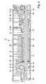
- Fig. 1 to 4 show a schematic representation of an exemplary embodiment of a door drive 10 according to the invention, in the illustration according to Fig. 1 for example, is provided as a top door closer for a revolving door.
- the door drive 10 includes a housing 12, a rotatably mounted on the housing 12 and coupled to a door leaf 14 or a frame 16 output shaft 18, a motor 20, in particular electric motor, for driving the output shaft 18 and a spring unit 22, during a respective opening movement of the Door leaf 14 is tensioned and relaxes during a respective closing movement of the door leaf 14 to provide a closing moment.
- the door drive 10 in the illustration according to Fig. 1 For example, provided as a top door closer for a revolving door, in the present case, the housing 12 attached to the output shaft 18 on the door 14 and the output shaft 18 is connected to a lever 24 which is provided with a sliding block or the like, which is guided in a slide rail 26 , which is fixed to the frame 16.
- the output shaft 18 is driven via a rack 28 by the motor 20 and the spring unit 22 on the one hand on the rack 28 and on the other hand supported by a stop 30 on the housing 12, which is adjustable relative to the housing 12 for adjusting the spring force of the spring unit 22 is.
- the spring unit 22 comprises a pushed onto the rack 28 compression spring which is supported at one end to the adjustable stop 30.
- the adjustable stop 30 is formed by the end face of a pushed onto the rack 28, relative to the housing 12 axially adjustable sleeve 32.
- the sleeve 32 is provided with an external thread 34 and screwed via this external thread 34 in the housing 12, which is provided with an internal thread 36.
- the sleeve 32 is provided with a helical toothing 38 and axially adjustable via a worm 40 meshing with the helical toothing 38.
- the housing 12 may be provided with at least one opening 42 (cf. Fig. 2 ), through which the respective spring preload of the spring unit 22 can be read.
- opening 42 which is designed in each case as a slot, is provided on opposite sides of the housing 12.
- the pushed onto the rack 28 spring unit 22 is disposed between the pushed onto the rack 28 and a sleeve 32 supported on the rack 28 bearing plate 44 which is also pushed back onto the rack 28 and, for example, at least one radial projection 46 of the rack 28th supported. Axially between the bearing plate 44 and the spring unit 22, a pushed onto the rack 28 thrust bearing 48 and a pushed onto the rack 28 intermediate sleeve 50 are arranged.
- the rack 28 can be acted upon by a gear 52 from the motor 20.
- the toothed rack 28 comprises a toothed portion 56 meshing with a pinion 54 of the gearbox 52 and a toothed portion 60 meshing with a toothing 58 of the output shaft 18.
- the toothed rod 28 comprises a wave-shaped toothing portion 60 meshing with a non-circular toothing 58 of the output shaft 18
- the toothed portion 56 of the toothed rack 28 meshing with the pinion 54 of the gearbox 52 can in particular be designed as a linear toothed portion.
- the rack 28 extends with its meshing with the pinion 54 of the gear 52 toothing portion 56 of the sleeve 32 out.
- the worm 40 is offset in the present case by 90 ° relative to the rack 28 and mounted in opposite gear housing shells 62.
- the worm 40 may be provided at both ends thereof with a receptacle for engagement of a tool.
- the screw 40 may be provided at its two ends, for example, each with a hexagon socket for receiving an Allen wrench. If the worm 40 is rotated by the relevant tool, then the sleeve 32 rotates via the helical gearing 38, whereby it is axially displaced relative to the housing 12 via its external thread 34, depending on the direction of rotation of the tool in one or the other direction. Thus, the bias of the spring unit 22 changes accordingly.
- the toothed rack 28 is in the region of its toothed portions 56, 60, which mesh with the pinion 54 of the gearbox 52 and with the toothing 58 of the output shaft 18, in each case via a roller, which is mounted on the side of the toothed rack 28 remote from the respective toothed portion 56, 60 or the like supported.
- the rack 28 can sit with the members pushed onto them in a housing portion 66 which is closed on one side by a lid 68 and on the other side by the sleeve 32.
- the cover 68 and the sleeve 32 may be screwed by threads in the housing portion 66.
- a bearing plate 70 may be screwed, which forms the bearing point for the output shaft 18 together with the housing portion 66.
- the worm 40 is seated in the two gear housing shells 62 with through-holes to the worm 40.
- the gear housing shells 62 also hold the housing section 66 with the spring unit 22.
- the sleeve 32 is on the one hand mounted in a form-fitting manner via the external thread 34 in the housing section 66 and on the other hand via the outside diameter of the helical gearing 38 supported in the two gear housing shells 62.
- the worm 40 sits in housing bores of the gear housing shells 62 and is thus positioned radially and axially.
- the spring force of the spring unit 22 is adjustable in a simple manner from two sides.
- the required structural effort is reduced to a minimum.
- the spring preload can be read through the example provided as slots holes 42 in the housing 12.
Landscapes
- Power-Operated Mechanisms For Wings (AREA)
Applications Claiming Priority (2)
| Application Number | Priority Date | Filing Date | Title |
|---|---|---|---|
| DE102014207217.4A DE102014207217B3 (de) | 2014-04-15 | 2014-04-15 | Drehtürantrieb |
| DE102015202832.1A DE102015202832B3 (de) | 2015-02-17 | 2015-02-17 | Türantrieb |
Publications (1)
| Publication Number | Publication Date |
|---|---|
| EP2933414A1 true EP2933414A1 (fr) | 2015-10-21 |
Family
ID=52811065
Family Applications (1)
| Application Number | Title | Priority Date | Filing Date |
|---|---|---|---|
| EP15162790.8A Withdrawn EP2933414A1 (fr) | 2014-04-15 | 2015-04-08 | Entraînement de porte |
Country Status (2)
| Country | Link |
|---|---|
| EP (1) | EP2933414A1 (fr) |
| CN (1) | CN105064847B (fr) |
Cited By (2)
| Publication number | Priority date | Publication date | Assignee | Title |
|---|---|---|---|---|
| IT201900006728A1 (it) * | 2019-05-10 | 2020-11-10 | Faac Spa | Attuatore motorizzato e barriera mobile provvista di tale attuatore. |
| SE2151116A1 (en) * | 2021-09-10 | 2023-03-11 | Assa Abloy Ab | Control arrangement for access member, and access member system |
Families Citing this family (5)
| Publication number | Priority date | Publication date | Assignee | Title |
|---|---|---|---|---|
| CN105428023A (zh) * | 2016-01-04 | 2016-03-23 | 黄常宇 | 一种具有限位功能的变压器安装装置 |
| DE102016200632A1 (de) * | 2016-01-19 | 2017-07-20 | Geze Gmbh | Elektromotorischer Antrieb |
| DE102018208585B4 (de) * | 2018-05-30 | 2022-06-09 | Geze Gmbh | Antrieb für einen Tür- oder Fensterflügel |
| US11974693B2 (en) * | 2018-06-27 | 2024-05-07 | Carimali S.P.A. | Brewing device for a beverage preparation machine, in particular coffee or tea |
| EP3683392B1 (fr) * | 2019-01-16 | 2023-07-12 | dormakaba Deutschland GmbH | Procédé de montage d'un entraînement de porte et entraînement de porte |
Citations (5)
| Publication number | Priority date | Publication date | Assignee | Title |
|---|---|---|---|---|
| US4590639A (en) * | 1982-06-29 | 1986-05-27 | Geze Gmbh | Door closer |
| EP0733763A1 (fr) * | 1995-03-21 | 1996-09-25 | GEZE GmbH & Co. | Ferme-porte |
| WO2001098615A1 (fr) * | 2000-06-19 | 2001-12-27 | Dorma Gmbh + Co. Kg | Dispositif d'ouverture et de fermeture d'une porte ou d'un portail |
| DE10148293A1 (de) * | 2001-09-29 | 2003-04-24 | Landert Motoren Ag | Flügeltürantrieb mit Federschliessung |
| US20070256362A1 (en) * | 2006-03-04 | 2007-11-08 | Curtis David Hansen | Assembly and method for automated operation of a restroom door |
Family Cites Families (4)
| Publication number | Priority date | Publication date | Assignee | Title |
|---|---|---|---|---|
| DE3524185A1 (de) * | 1985-07-05 | 1987-01-15 | Geze Gmbh | Tuerschliesser |
| US5243735A (en) * | 1992-03-09 | 1993-09-14 | Thomas Industries, Inc. | Regenerative feedback door control device with one-way clutch |
| GB2338028B (en) * | 1998-05-28 | 2002-11-20 | Nt Dor O Matic Inc | Automatic door operator |
| DE102006026008A1 (de) * | 2006-06-01 | 2007-12-06 | Dorma Gmbh + Co. Kg | Türantrieb mit während der Türbewegung veränderbarer Federvorspannung |
-
2015
- 2015-04-08 EP EP15162790.8A patent/EP2933414A1/fr not_active Withdrawn
- 2015-04-15 CN CN201510409319.4A patent/CN105064847B/zh not_active Expired - Fee Related
Patent Citations (5)
| Publication number | Priority date | Publication date | Assignee | Title |
|---|---|---|---|---|
| US4590639A (en) * | 1982-06-29 | 1986-05-27 | Geze Gmbh | Door closer |
| EP0733763A1 (fr) * | 1995-03-21 | 1996-09-25 | GEZE GmbH & Co. | Ferme-porte |
| WO2001098615A1 (fr) * | 2000-06-19 | 2001-12-27 | Dorma Gmbh + Co. Kg | Dispositif d'ouverture et de fermeture d'une porte ou d'un portail |
| DE10148293A1 (de) * | 2001-09-29 | 2003-04-24 | Landert Motoren Ag | Flügeltürantrieb mit Federschliessung |
| US20070256362A1 (en) * | 2006-03-04 | 2007-11-08 | Curtis David Hansen | Assembly and method for automated operation of a restroom door |
Cited By (6)
| Publication number | Priority date | Publication date | Assignee | Title |
|---|---|---|---|---|
| IT201900006728A1 (it) * | 2019-05-10 | 2020-11-10 | Faac Spa | Attuatore motorizzato e barriera mobile provvista di tale attuatore. |
| EP3736402A1 (fr) * | 2019-05-10 | 2020-11-11 | FAAC S.p.A. | Actionneur motorisé et barriere pourvu d'un tel actionneur |
| US11802433B2 (en) | 2019-05-10 | 2023-10-31 | Faac S.P.A. | Motorized actuator and movable barrier provided with said actuator |
| SE2151116A1 (en) * | 2021-09-10 | 2023-03-11 | Assa Abloy Ab | Control arrangement for access member, and access member system |
| SE545566C2 (en) * | 2021-09-10 | 2023-10-24 | Assa Abloy Ab | Control arrangement for controlling an access member |
| US12644327B2 (en) | 2021-09-10 | 2026-06-02 | Assa Abloy Ab | Control arrangement for access member, and access member system |
Also Published As
| Publication number | Publication date |
|---|---|
| HK1217037A1 (zh) | 2016-12-16 |
| CN105064847A (zh) | 2015-11-18 |
| CN105064847B (zh) | 2017-10-27 |
Similar Documents
| Publication | Publication Date | Title |
|---|---|---|
| EP2933415B1 (fr) | Entraînement de porte | |
| EP2841667B1 (fr) | Entrainement pour porte pivotante | |
| EP1298274B1 (fr) | Mécanisme d'entraínement de portes à battants avec dipositif de fermeture à ressort | |
| DE102016209161B4 (de) | Stelleinrichtung und Verwendung der Stelleinrichtung | |
| EP3325751A1 (fr) | Entraînement d'un battant pivotant | |
| EP4314459B1 (fr) | Entraînement destiné à une porte ou à une fenêtre | |
| DE102014207217B3 (de) | Drehtürantrieb | |
| DE102015202832B3 (de) | Türantrieb | |
| DE102015202830B3 (de) | Türantrieb | |
| EP2933413B1 (fr) | Entraînement de porte | |
| DE102015211503B4 (de) | Türantrieb | |
| EP1722050B1 (fr) | Serrure à verrou rotatif | |
| EP2933410A1 (fr) | Entraînement de porte | |
| EP1375812A2 (fr) | Système d'entraínement pour un ensemble de lamelles | |
| EP2594711B1 (fr) | Dispositif de fermeture électromécanique avec une installation de fermeture rapide | |
| EP3913171B1 (fr) | Entraînement de verrouillage et/ou de positionnement pour une fenêtre, une porte ou similaire | |
| DE3342191A1 (de) | Getriebe fuer treibstangen an fenstern, tueren o.dgl. | |
| DE102015202852B3 (de) | Türantrieb | |
| DE102015202835B3 (de) | Türantrieb | |
| DE10030607A1 (de) | Getriebe | |
| DE102024107399B3 (de) | Antrieb für eine Tür oder ein Fenster mit verbessertem Wirkungsgrad | |
| EP2832946A1 (fr) | Levier pour un actionnement de porte | |
| DE102023208573B3 (de) | Automatischer Antrieb für eine Drehtür und Drehtür | |
| DE9017796U1 (de) | Manuell betreibbarer Notantrieb | |
| EP2960415B1 (fr) | Entrainement de porte |
Legal Events
| Date | Code | Title | Description |
|---|---|---|---|
| PUAI | Public reference made under article 153(3) epc to a published international application that has entered the european phase |
Free format text: ORIGINAL CODE: 0009012 |
|
| AK | Designated contracting states |
Kind code of ref document: A1 Designated state(s): AL AT BE BG CH CY CZ DE DK EE ES FI FR GB GR HR HU IE IS IT LI LT LU LV MC MK MT NL NO PL PT RO RS SE SI SK SM TR |
|
| AX | Request for extension of the european patent |
Extension state: BA ME |
|
| 17P | Request for examination filed |
Effective date: 20160127 |
|
| RBV | Designated contracting states (corrected) |
Designated state(s): AL AT BE BG CH CY CZ DE DK EE ES FI FR GB GR HR HU IE IS IT LI LT LU LV MC MK MT NL NO PL PT RO RS SE SI SK SM TR |
|
| STAA | Information on the status of an ep patent application or granted ep patent |
Free format text: STATUS: EXAMINATION IS IN PROGRESS |
|
| 17Q | First examination report despatched |
Effective date: 20181123 |
|
| GRAP | Despatch of communication of intention to grant a patent |
Free format text: ORIGINAL CODE: EPIDOSNIGR1 |
|
| STAA | Information on the status of an ep patent application or granted ep patent |
Free format text: STATUS: GRANT OF PATENT IS INTENDED |
|
| INTG | Intention to grant announced |
Effective date: 20220705 |
|
| STAA | Information on the status of an ep patent application or granted ep patent |
Free format text: STATUS: THE APPLICATION HAS BEEN WITHDRAWN |
|
| 18W | Application withdrawn |
Effective date: 20221017 |