EP2594716A2 - Ferme-porte avec dispositif de retenue - Google Patents
Ferme-porte avec dispositif de retenue Download PDFInfo
- Publication number
- EP2594716A2 EP2594716A2 EP12006818.4A EP12006818A EP2594716A2 EP 2594716 A2 EP2594716 A2 EP 2594716A2 EP 12006818 A EP12006818 A EP 12006818A EP 2594716 A2 EP2594716 A2 EP 2594716A2
- Authority
- EP
- European Patent Office
- Prior art keywords
- drive unit
- door closer
- door
- latching lug
- output shaft
- Prior art date
- Legal status (The legal status is an assumption and is not a legal conclusion. Google has not performed a legal analysis and makes no representation as to the accuracy of the status listed.)
- Withdrawn
Links
- 230000000295 complement effect Effects 0.000 claims abstract description 4
- 230000005540 biological transmission Effects 0.000 claims description 4
- 238000013519 translation Methods 0.000 abstract description 2
- 230000000903 blocking effect Effects 0.000 abstract 1
- 239000012530 fluid Substances 0.000 abstract 1
- 238000000034 method Methods 0.000 description 3
- 238000013461 design Methods 0.000 description 2
- 238000009434 installation Methods 0.000 description 2
- 238000012423 maintenance Methods 0.000 description 2
- 238000004519 manufacturing process Methods 0.000 description 2
- 208000010543 22q11.2 deletion syndrome Diseases 0.000 description 1
- 238000006243 chemical reaction Methods 0.000 description 1
- 230000009849 deactivation Effects 0.000 description 1
- 230000001419 dependent effect Effects 0.000 description 1
- 238000011161 development Methods 0.000 description 1
- 230000018109 developmental process Effects 0.000 description 1
- 238000003825 pressing Methods 0.000 description 1
Images




Classifications
-
- E—FIXED CONSTRUCTIONS
- E05—LOCKS; KEYS; WINDOW OR DOOR FITTINGS; SAFES
- E05F—DEVICES FOR MOVING WINGS INTO OPEN OR CLOSED POSITION; CHECKS FOR WINGS; WING FITTINGS NOT OTHERWISE PROVIDED FOR, CONCERNED WITH THE FUNCTIONING OF THE WING
- E05F3/00—Closers or openers with braking devices, e.g. checks; Construction of pneumatic or liquid braking devices
- E05F3/04—Closers or openers with braking devices, e.g. checks; Construction of pneumatic or liquid braking devices with liquid piston brakes
- E05F3/10—Closers or openers with braking devices, e.g. checks; Construction of pneumatic or liquid braking devices with liquid piston brakes with a spring, other than a torsion spring, and a piston, the axes of which are the same or lie in the same direction
-
- E—FIXED CONSTRUCTIONS
- E05—LOCKS; KEYS; WINDOW OR DOOR FITTINGS; SAFES
- E05F—DEVICES FOR MOVING WINGS INTO OPEN OR CLOSED POSITION; CHECKS FOR WINGS; WING FITTINGS NOT OTHERWISE PROVIDED FOR, CONCERNED WITH THE FUNCTIONING OF THE WING
- E05F3/00—Closers or openers with braking devices, e.g. checks; Construction of pneumatic or liquid braking devices
- E05F3/04—Closers or openers with braking devices, e.g. checks; Construction of pneumatic or liquid braking devices with liquid piston brakes
- E05F3/10—Closers or openers with braking devices, e.g. checks; Construction of pneumatic or liquid braking devices with liquid piston brakes with a spring, other than a torsion spring, and a piston, the axes of which are the same or lie in the same direction
- E05F3/104—Closers or openers with braking devices, e.g. checks; Construction of pneumatic or liquid braking devices with liquid piston brakes with a spring, other than a torsion spring, and a piston, the axes of which are the same or lie in the same direction with cam-and-slide transmission between driving shaft and piston within the closer housing
-
- E—FIXED CONSTRUCTIONS
- E05—LOCKS; KEYS; WINDOW OR DOOR FITTINGS; SAFES
- E05F—DEVICES FOR MOVING WINGS INTO OPEN OR CLOSED POSITION; CHECKS FOR WINGS; WING FITTINGS NOT OTHERWISE PROVIDED FOR, CONCERNED WITH THE FUNCTIONING OF THE WING
- E05F3/00—Closers or openers with braking devices, e.g. checks; Construction of pneumatic or liquid braking devices
- E05F3/22—Additional arrangements for closers, e.g. for holding the wing in opened or other position
- E05F3/221—Mechanical power-locks, e.g. for holding the wing open or for free-moving zones
- E05F3/222—Mechanical power-locks, e.g. for holding the wing open or for free-moving zones electrically operated
-
- E—FIXED CONSTRUCTIONS
- E05—LOCKS; KEYS; WINDOW OR DOOR FITTINGS; SAFES
- E05Y—INDEXING SCHEME ASSOCIATED WITH SUBCLASSES E05D AND E05F, RELATING TO CONSTRUCTION ELEMENTS, ELECTRIC CONTROL, POWER SUPPLY, POWER SIGNAL OR TRANSMISSION, USER INTERFACES, MOUNTING OR COUPLING, DETAILS, ACCESSORIES, AUXILIARY OPERATIONS NOT OTHERWISE PROVIDED FOR, APPLICATION THEREOF
- E05Y2201/00—Constructional elements; Accessories therefor
- E05Y2201/40—Motors; Magnets; Springs; Weights; Accessories therefor
- E05Y2201/46—Magnets
- E05Y2201/462—Electromagnets
-
- E—FIXED CONSTRUCTIONS
- E05—LOCKS; KEYS; WINDOW OR DOOR FITTINGS; SAFES
- E05Y—INDEXING SCHEME ASSOCIATED WITH SUBCLASSES E05D AND E05F, RELATING TO CONSTRUCTION ELEMENTS, ELECTRIC CONTROL, POWER SUPPLY, POWER SIGNAL OR TRANSMISSION, USER INTERFACES, MOUNTING OR COUPLING, DETAILS, ACCESSORIES, AUXILIARY OPERATIONS NOT OTHERWISE PROVIDED FOR, APPLICATION THEREOF
- E05Y2201/00—Constructional elements; Accessories therefor
- E05Y2201/40—Motors; Magnets; Springs; Weights; Accessories therefor
- E05Y2201/47—Springs
- E05Y2201/474—Compression springs
-
- E—FIXED CONSTRUCTIONS
- E05—LOCKS; KEYS; WINDOW OR DOOR FITTINGS; SAFES
- E05Y—INDEXING SCHEME ASSOCIATED WITH SUBCLASSES E05D AND E05F, RELATING TO CONSTRUCTION ELEMENTS, ELECTRIC CONTROL, POWER SUPPLY, POWER SIGNAL OR TRANSMISSION, USER INTERFACES, MOUNTING OR COUPLING, DETAILS, ACCESSORIES, AUXILIARY OPERATIONS NOT OTHERWISE PROVIDED FOR, APPLICATION THEREOF
- E05Y2900/00—Application of doors, windows, wings or fittings thereof
- E05Y2900/10—Application of doors, windows, wings or fittings thereof for buildings or parts thereof
- E05Y2900/13—Type of wing
- E05Y2900/132—Doors
Definitions
- the present invention relates to a door closer for actuating a door leaf with a locking device.
- Door closers usually comprise an output shaft and a closing spring designed to store the closing energy.
- the output shaft By pressing the door by a user, the output shaft is rotated. The movement is transmitted within the door closer to the closing spring and thus stores the energy required to close the door. During the closing process, the closing spring relaxes. This leads to the rotation of the output shaft and consequently to the movement of the door leaf.
- the door closer can be attached directly to the door leaf. In this case, the power transmission from the output shaft to the wall or to the frame via a scissor linkage or a slide rail linkage takes place. On the other hand, the door closer can also be attached to the frame or on the wall. Then, the power is transmitted from the output shaft to the door by means of a slide rail linkage or a scissors linkage.
- a slide rail is usually used.
- this slide is an external locking device for fixing a slide rail lever.
- the disadvantage is that due to the small slides only correspondingly small holding forces can be realized.
- the maximum pivoting range of the door is limited by previously known, not traversable systems within the slide rail. Scissors linkage can not be combined with these known locking devices.
- both the setting and the wiring of the known external locking devices impractical.
- the previously known locking devices are often optically not appealing and after initial installation no longer changeable.
- Other previously known solutions are mounted on the floor and usually disturb the user of the door.
- hydraulic systems are known in which individual components are blocked within the door closer by means of hydraulic pressure or clearance spaces. In these variants, both the production and maintenance and the scheme is very expensive.
- a door closer for actuating a door leaf comprising an output shaft and a drive unit for the translation between a rotation of the output shaft and a linear movement of the drive unit. If the door closer is fastened directly to the door leaf, the output shaft serves to transmit power to a wall or frame by means of a linkage. If the door closer fixed to a wall or a frame, so the output shaft is used for power transmission by means of a linkage to the door leaf.
- the axis of rotation of the door leaf can be connected coaxially to the output shaft.
- a first latching lug is coupled to the drive unit.
- the door closer comprises a locking device designed to block and release the drive unit with one to the first Detent nose complementary second detent.
- “Complementary locking lugs” means in this context that the two locking lugs are adapted to form a positive engagement with each other.
- the door closer comprises a fluid-tight housing for receiving the drive unit.
- the output shaft protrudes.
- the door closer comprises a rod, which is coupled with a first end to the drive unit and protrudes with the second end of the fluid-tight housing. At the second end of the rod, outside the fluid-tight housing, there is the first latch.
- the locking device can be arranged outside the fluid-tight housing.
- the fluid-tight housing is filled in particular with oil in order to ensure a low-friction mounting of the drive unit.
- a closer spring particularly preferably acts on the drive unit.
- the closing spring is arranged in particular in the fluid-tight housing. In particular, one end of the closing spring is supported on a fixed end of the housing. The other end of the closing spring is applied to the drive unit.
- the rod preferably extends from the drive unit through the helical shutter spring to the locking device.
- the locking device preferably comprises an electromagnet for actuating the second latching lug.
- the electromagnet is arranged such that, when energized, it makes it possible to lock the first latching lug.
- the solenoid is deactivated.
- the first locking lug releases from the locking device and the door is closed, in particular by means of the force of the closing spring.
- first latching lug and / or the second latching lug are rotatably mounted.
- a first spring generates a torque on the first detent and / or a second spring a torque on the second detent.
- the second latching lug is located on a lever, wherein this lever is mounted on the locking device via a rotation axis. On one side of the axis of rotation is the second detent. On the other side of the axis of rotation of the electromagnet acts.
- a first lever arm from the second latching lug to the rotation axis is in particular shorter than a second lever arm from the rotation axis to the electromagnet.
- the door closer particularly preferably comprises a common mounting plate on which the housing and the locking device are mounted.
- the locking device is fastened by means of an adjusting device on the mounting plate. This makes it possible to set a distance between the first latching lug and the second latching lug, whereby ultimately the opening angle of the door is set at which the locking device engages.
- the door closer with locking device can now serve on the one hand for fixing the door leaf or on the other hand only for detecting the closing spring. If only the closing spring is detected, then the door is in the so-called "freewheel". During this freewheel, the door can be opened and closed with a very small amount of force because the closing spring does not have to be tensioned during the opening process.
- the door closer comprises an overrunning clutch between the first latching lug and the output shaft, so that with the locking device, only the closing spring, but not the output shaft is blocked.
- the drive unit may comprise a toothed rack.
- a gear is then arranged, which is in engagement with the rack of the drive unit.
- the drive unit is designed as a, in the housing sliding piston. This piston is slotted and includes the rack inside the slot. If in this case the door closer according to the invention is used for fixing the entire door leaf, then the first latching lug is firmly connected to the drive unit, in particular this piston.
- the first latch is firmly connected to the second end of the rod. The rod is connected to the first end fixed to the drive unit. To realize a freewheel of the door also the rod is used.
- a plate At the first end of the rod is then a plate. This plate is loosely attached to the drive unit. Furthermore, the closing spring is supported at one end against the plate and at the other end against the housing. When opening the door for the first time, the closing spring is pre-tensioned via the drive unit and the plate. Then the rod is blocked with the locking device according to the invention. When re-closing the door manually, the drive unit lifts off the plate and is free to move without being spring-loaded. Only when releasing the locking device relaxes the closing spring and it comes to rest the plate on the drive unit and thus spring-loaded closing the door.
- a cam disc is arranged on the output shaft.
- the drive unit then comprises at least one pressure roller for transmitting power to the cam disk.
- This pressure roller is arranged in particular in an opening piston.
- This opening piston slides in the housing.
- a closing piston is still provided in the housing.
- another pressure roller is arranged, which also rolls on the cam.
- FIGS. 1 to 6 Based on FIGS. 1 to 6 a door closer 1 according to the first embodiment will be explained in more detail.
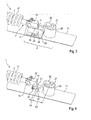
- FIG. 1 shows the door closer 1 with a housing 2 and a locking device 8, mounted on a mounting plate 11. From the housing 2 protrudes an output shaft 3. At this output shaft 3 either the door is mounted directly or there is a linkage to the output shaft 3 for power transmission on the door or on the wall.
- the housing 2 is designed cylindrical and closed at the two end faces with a first closure lid 9 and a second closure lid 10.
- the housing 2 is formed fluid-tight and in particular filled with oil. Through the second cap 10, a rod 5 protrudes. This state 5 is by means of the locking device. 8 blocked and released.
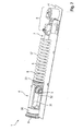
- the detailed structure of the door closer 1 shows the FIG. 2 ,
- the drive unit 4 comprises an opening piston 12 and a closing piston 14.
- the two pistons 12, 14 are guided in the housing 2.
- the output shaft 3 is arranged.
- a cam 16 On the output shaft 3 is a cam 16.
- a first pressure roller 13 is mounted in the opening piston 12.
- a second pressure roller 15 is mounted in the closing piston 14.
- the first and second pressure rollers 13, 15 roll on two opposite sides of the cam disk 16.
- a closing spring 17 is located in the housing 2. One end of the closing spring 17 bears against the opening piston 12. With the other end, the closing spring 17 is supported against a stationary end of the housing 2, in particular against the second closure lid 10.
- the rod 5 is coupled with a first end to the drive unit 4, in particular to the opening piston 12. A second end 7 of the rod 5 protrudes through the second closure lid 10, so that the second end 7 of the rod 5 is located outside the fluid-tight housing 2.
- the closing spring 17 is designed as a spiral spring, so that the rod 5 can extend through the closing spring 17 therethrough.
- the output shaft 3 When opening the door leaf, the output shaft 3 is rotated. Thereafter, the opening piston 12 and the closing piston 14 moves to the right. During the closing operation, the opening piston 12 and the closing piston 14 move to the left, whereby the force is transmitted to the cam disk 16 via the pressure roller 13. This results in a conversion of the linear movement of the drive unit 4 in a rotational Movement of the output shaft 3.
- the exact structure of the locking device 8 will be described below with reference to the FIGS. 3 and 4 explained in more detail.
- FIG. 3 shows in detail the second end 7 of the rod 5 and the locking device 8.
- the housing 2 and the second closure lid 10 are hidden for clarity.
- a first latching lug 18 is connected to the rod 5 via a first pivot bearing 19.
- the latching nose is spring-loaded by means of a first spring 20.
- the first spring 20 generates a torque on the first latching lug 18 about the first axis of rotation 19.
- the locking device 8 comprises a bearing block 24, a second latching lug 21 and an electromagnet 28.
- the second latching lug 21 is connected via a second pivot bearing 22 with the bearing block 24.
- the second detent 21 is fixedly connected to a lever arm 26.
- On the one side of the second axis of rotation 22 is the second detent 21.
- On the other side of the second axis of rotation 22 extends the lever arm 26.
- a compensating element 27 At the end of the lever arm 26 is a compensating element 27 in the form of a disc. On this compensating element 27, the force of the electromagnet 28 acts.
- the bearing block 24 is connected via an adjusting device 25 with the mounting plate 11.
- the adjusting device 25 is formed here as a slot. Through this slot, the bearing block 24 is screwed to the mounting plate 11.
- FIG. 4 the bearing block 24 is hidden. As a result, a second spring 23 is visible, the spring-loaded the second latching lug 2 on train and thus generates a moment about the second axis of rotation 22.
- FIG. 4 shows a first lever arm H1 between the second locking lug 23 and the second axis of rotation 22 and a second lever arm H2 between a center of the electromagnet 28 and the second axis of rotation 22.
- the first lever arm H1 is smaller than the second lever arm H2.
- the second lever arm H2 is preferably twice, in particular three, as long as the first lever arm H1.
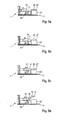
- FIGS. 5a to 5d show a movement of the door closer 1 according to the first embodiment.
- the FIGS. 5a and 5b show the door closer 1 during the opening process.
- the first latching lug 18 moves toward the second latching lug 21.
- the first latching lug 18 lifts against the spring force of the first spring 20 against.
- FIG. 5c engages the first locking lug 18 behind the second latch 21 at a corresponding door opening angle.
- the solenoid 28 is energized and holds on the lever arm 26, the second locking lug 21 in the position shown. In the in FIG. 5c shown position, the first locking lug 18 and the rod 5 are blocked.
- the magnet 28 is deactivated.
- the second latching lug 21 can be moved downwards against the second spring 23 and thus the first latching lug 18 can be released. This is followed by a relaxation of the closing spring 17 and a closing of the door leaf.
- FIG. 6 shows the door closer 1 according to the first embodiment with a cover 29.
- the cover 29 is on the mounting plate 11th attached and covers the housing and the locking device 8.
- the cover 29 is not a supporting element of the door closer 1, but serves to visually appealing cover of the door closer. 1
- FIG. 7 shows a second embodiment of the door closer 1.
- the drive unit 4 comprises a drive piston 30.
- This drive piston 30 is slotted. Within the slot is a rack 31.
- a gear 32 is arranged on the output shaft 3, arranged. The gear 32 is engaged with the rack 31.
- the door closers 1 With the door closers 1 according to the two embodiments, a locking of the closing spring 17 and at the same time the door leaf done.
- the determination of the closing spring 17 and the simultaneous fixing of the door leaf the first locking lug 18 is fixedly connected to the drive unit 4.
- the first end 6 of the rod 5 is fixedly connected to the opening piston 12.
- the opening piston 12 is preferably fixedly connected to the closing piston 14.
- the first end 6 of the rod 5 is fixedly connected to the drive piston 30.
- an overrunning clutch between the first latching lug 18 and the output shaft 3 is provided.
- the second embodiment according to FIG. 7 there is a plate 33 between the closing spring 17 and the drive unit 4. This plate 33 is fixedly connected to the first end 6 of the rod 5. The other end is the Drive piston 30 to the plate 33 only on.
- the closing spring 17 is supported with its left end against the plate 33.
- the drive piston 30 lifts off from the plate 33.
- the locking device releases and the closing spring 17 relaxes. This will close the door.
- the plate 33 would also be located between the closing spring 17 and the opening shoulder 12.
- the opening piston 12 and the closing piston 14 are not firmly connected to each other. As a result, when locking the locking device, the closing piston 14 to move to the left and thus an approximately free rotation of the output shaft 3 is possible.
- FIGS. 8 and 9 show the door closer 1 according to a third embodiment. Identical or functionally identical components are provided with the same reference numerals in all embodiments. In the FIGS. 8 and 9 again the housing is hidden. In essence, the third embodiment corresponds to the first embodiment with the exception that the door closer 1 shown here serves not only for fixing the closing spring, but for fixing the door. For this purpose, the opening piston 12 and the closing piston 14 are firmly connected to each other.
- FIG. 9 shows a section FIG. 8 in detail.
- a first end of the connecting rods 35 is fixedly connected to the opening piston 12.
- the other ends of the connecting rods 35 extend through the closing piston 14 and are fixedly connected to a further plate 34 on the side of the closing piston 14 facing away from the cam disk. This further plate 34 abuts the closing piston 14.
- the closing piston 14 is fixedly connected to the opening piston 12.
- the rod 5 is fixedly connected to the opening piston 12.
- the cam disk 16 with the output shaft 3 is also set between the opening piston 12 and the closing piston 14. As a result, the entire door is locked in its position.
Landscapes
- Engineering & Computer Science (AREA)
- Mechanical Engineering (AREA)
- Power-Operated Mechanisms For Wings (AREA)
Applications Claiming Priority (1)
| Application Number | Priority Date | Filing Date | Title |
|---|---|---|---|
| DE201110055490 DE102011055490A1 (de) | 2011-11-18 | 2011-11-18 | Türschließer mit Feststellvorrichtung |
Publications (1)
| Publication Number | Publication Date |
|---|---|
| EP2594716A2 true EP2594716A2 (fr) | 2013-05-22 |
Family
ID=47115126
Family Applications (1)
| Application Number | Title | Priority Date | Filing Date |
|---|---|---|---|
| EP12006818.4A Withdrawn EP2594716A2 (fr) | 2011-11-18 | 2012-10-01 | Ferme-porte avec dispositif de retenue |
Country Status (2)
| Country | Link |
|---|---|
| EP (1) | EP2594716A2 (fr) |
| DE (1) | DE102011055490A1 (fr) |
Cited By (1)
| Publication number | Priority date | Publication date | Assignee | Title |
|---|---|---|---|---|
| CN107435477A (zh) * | 2017-09-07 | 2017-12-05 | 丽水市神飞利益保安用品有限公司 | 电控液压闭门器 |
Families Citing this family (1)
| Publication number | Priority date | Publication date | Assignee | Title |
|---|---|---|---|---|
| CN108590416B (zh) * | 2018-04-19 | 2021-03-16 | 上海冉能自动化科技有限公司 | 闭门器用止动卡扣杠杆式传动结构 |
-
2011
- 2011-11-18 DE DE201110055490 patent/DE102011055490A1/de not_active Withdrawn
-
2012
- 2012-10-01 EP EP12006818.4A patent/EP2594716A2/fr not_active Withdrawn
Non-Patent Citations (1)
| Title |
|---|
| None |
Cited By (1)
| Publication number | Priority date | Publication date | Assignee | Title |
|---|---|---|---|---|
| CN107435477A (zh) * | 2017-09-07 | 2017-12-05 | 丽水市神飞利益保安用品有限公司 | 电控液压闭门器 |
Also Published As
| Publication number | Publication date |
|---|---|
| DE102011055490A1 (de) | 2013-05-23 |
Similar Documents
| Publication | Publication Date | Title |
|---|---|---|
| EP2841667B1 (fr) | Entrainement pour porte pivotante | |
| EP2318624B1 (fr) | Mécanisme d'ouverture de porte à réglage automatique du pêne d'ouverture | |
| DE10347528B3 (de) | Türöffner | |
| EP3105396A1 (fr) | Ensemble palier de porte | |
| EP4386158A1 (fr) | Ouvre-porte | |
| EP2594716A2 (fr) | Ferme-porte avec dispositif de retenue | |
| WO2010102979A1 (fr) | Dispositif de rappel pour mécanisme d'entraînement de portes | |
| DE102012104450B4 (de) | Antrieb für einen Türflügel oder einen Fensterflügel | |
| DE102016123516A1 (de) | Freilauftürschließer | |
| DE102016210986A1 (de) | Vorrichtung zum Feststellen eines Tür- oder Fensterflügels | |
| DE102011018732A1 (de) | Aufsatz für Schwenktürbetätiger | |
| EP3614062A1 (fr) | Dispositif de gaz d'échappement | |
| DE102007057220A1 (de) | Mechanismus zum Betätigen von Klappen, Ventilen und anderen mit Zu- und Aufhaltemoment beaufschlagten Einrichtungen | |
| DE19532262B4 (de) | Vorrichtung zur Schließfolgeregelung für zweiflügelige Türen | |
| DE10361085B4 (de) | Hydraulisch-mechanische Schließfolgeregelung | |
| EP2672046A2 (fr) | Agencement de rail de guidage | |
| EP2735681B1 (fr) | Entraînement pour un battant de porte ou de fenêtre | |
| DE102011018738A1 (de) | Drehflügeltürbetätigeraufsatz | |
| EP4146966A1 (fr) | Entraînement à sûreté intégrée et mécanisme de commande pourvu d'un entraînement à sûreté intégrée | |
| EP2738333A2 (fr) | Ferme-porte | |
| DE102013022158B3 (de) | Türschließer | |
| DE10107460A1 (de) | Schließfolgeregler | |
| DE19532263B4 (de) | Vorrichtung zur Schließfolgeregelung für zweiflügelige Türen | |
| EP3287577B1 (fr) | Dispositif de fermeture de porte, fenêtre ou analogue | |
| EP1620626B2 (fr) | Sequence de fermeture mecano-hydraulique |
Legal Events
| Date | Code | Title | Description |
|---|---|---|---|
| PUAI | Public reference made under article 153(3) epc to a published international application that has entered the european phase |
Free format text: ORIGINAL CODE: 0009012 |
|
| AK | Designated contracting states |
Kind code of ref document: A2 Designated state(s): AL AT BE BG CH CY CZ DE DK EE ES FI FR GB GR HR HU IE IS IT LI LT LU LV MC MK MT NL NO PL PT RO RS SE SI SK SM TR |
|
| AX | Request for extension of the european patent |
Extension state: BA ME |
|
| STAA | Information on the status of an ep patent application or granted ep patent |
Free format text: STATUS: THE APPLICATION HAS BEEN WITHDRAWN |
|
| 18W | Application withdrawn |
Effective date: 20140131 |