EP2596899A2 - Dispositif et procédé de structuration par interférences d'échantillons plats - Google Patents
Dispositif et procédé de structuration par interférences d'échantillons plats Download PDFInfo
- Publication number
- EP2596899A2 EP2596899A2 EP12193414.5A EP12193414A EP2596899A2 EP 2596899 A2 EP2596899 A2 EP 2596899A2 EP 12193414 A EP12193414 A EP 12193414A EP 2596899 A2 EP2596899 A2 EP 2596899A2
- Authority
- EP
- European Patent Office
- Prior art keywords
- sample
- spatial direction
- sample volume
- partial beams
- arrangement
- Prior art date
- Legal status (The legal status is an assumption and is not a legal conclusion. Google has not performed a legal analysis and makes no representation as to the accuracy of the status listed.)
- Granted
Links
Images




Classifications
-
- B—PERFORMING OPERATIONS; TRANSPORTING
- B23—MACHINE TOOLS; METAL-WORKING NOT OTHERWISE PROVIDED FOR
- B23K—SOLDERING OR UNSOLDERING; WELDING; CLADDING OR PLATING BY SOLDERING OR WELDING; CUTTING BY APPLYING HEAT LOCALLY, e.g. FLAME CUTTING; WORKING BY LASER BEAM
- B23K26/00—Working by laser beam, e.g. welding, cutting or boring
- B23K26/36—Removing material
- B23K26/362—Laser etching
- B23K26/364—Laser etching for making a groove or trench, e.g. for scribing a break initiation groove
-
- B—PERFORMING OPERATIONS; TRANSPORTING
- B23—MACHINE TOOLS; METAL-WORKING NOT OTHERWISE PROVIDED FOR
- B23K—SOLDERING OR UNSOLDERING; WELDING; CLADDING OR PLATING BY SOLDERING OR WELDING; CUTTING BY APPLYING HEAT LOCALLY, e.g. FLAME CUTTING; WORKING BY LASER BEAM
- B23K26/00—Working by laser beam, e.g. welding, cutting or boring
- B23K26/02—Positioning or observing the workpiece, e.g. with respect to the point of impact; Aligning, aiming or focusing the laser beam
- B23K26/06—Shaping the laser beam, e.g. by masks or multi-focusing
- B23K26/0604—Shaping the laser beam, e.g. by masks or multi-focusing by a combination of beams
-
- B—PERFORMING OPERATIONS; TRANSPORTING
- B23—MACHINE TOOLS; METAL-WORKING NOT OTHERWISE PROVIDED FOR
- B23K—SOLDERING OR UNSOLDERING; WELDING; CLADDING OR PLATING BY SOLDERING OR WELDING; CUTTING BY APPLYING HEAT LOCALLY, e.g. FLAME CUTTING; WORKING BY LASER BEAM
- B23K26/00—Working by laser beam, e.g. welding, cutting or boring
- B23K26/02—Positioning or observing the workpiece, e.g. with respect to the point of impact; Aligning, aiming or focusing the laser beam
- B23K26/06—Shaping the laser beam, e.g. by masks or multi-focusing
- B23K26/067—Dividing the beam into multiple beams, e.g. multi-focusing
- B23K26/0676—Dividing the beam into multiple beams, e.g. multi-focusing into dependently operating sub-beams, e.g. an array of spots with fixed spatial relationship or for performing simultaneously identical operations
-
- B—PERFORMING OPERATIONS; TRANSPORTING
- B23—MACHINE TOOLS; METAL-WORKING NOT OTHERWISE PROVIDED FOR
- B23K—SOLDERING OR UNSOLDERING; WELDING; CLADDING OR PLATING BY SOLDERING OR WELDING; CUTTING BY APPLYING HEAT LOCALLY, e.g. FLAME CUTTING; WORKING BY LASER BEAM
- B23K26/00—Working by laser beam, e.g. welding, cutting or boring
- B23K26/02—Positioning or observing the workpiece, e.g. with respect to the point of impact; Aligning, aiming or focusing the laser beam
- B23K26/06—Shaping the laser beam, e.g. by masks or multi-focusing
- B23K26/073—Shaping the laser spot
-
- B—PERFORMING OPERATIONS; TRANSPORTING
- B23—MACHINE TOOLS; METAL-WORKING NOT OTHERWISE PROVIDED FOR
- B23K—SOLDERING OR UNSOLDERING; WELDING; CLADDING OR PLATING BY SOLDERING OR WELDING; CUTTING BY APPLYING HEAT LOCALLY, e.g. FLAME CUTTING; WORKING BY LASER BEAM
- B23K26/00—Working by laser beam, e.g. welding, cutting or boring
- B23K26/352—Working by laser beam, e.g. welding, cutting or boring for surface treatment
- B23K26/355—Texturing
-
- B—PERFORMING OPERATIONS; TRANSPORTING
- B23—MACHINE TOOLS; METAL-WORKING NOT OTHERWISE PROVIDED FOR
- B23K—SOLDERING OR UNSOLDERING; WELDING; CLADDING OR PLATING BY SOLDERING OR WELDING; CUTTING BY APPLYING HEAT LOCALLY, e.g. FLAME CUTTING; WORKING BY LASER BEAM
- B23K26/00—Working by laser beam, e.g. welding, cutting or boring
- B23K26/36—Removing material
- B23K26/361—Removing material for deburring or mechanical trimming
Definitions
- the present invention relates to the structuring of flat samples with laser systems, in particular with fiber lasers and / or with laser systems with a high pulse frequency.
- the US 2003/0035219 A1 describes a device for interference structuring of a flat sample. It has a laser and an expansion and separation arrangement arranged in the beam path of the laser, with which the laser beam can be expanded in one spatial direction and can be split into two partial beams. The two partial beams are directed to a sample volume where they interfere.
- the WO 2011/072663 A2 describes a device for interference structuring, in which a telescope is arranged before a separation arrangement. The telescope is used to control and adjust the beam diameter.
- the JP 2006 110587 A describes a widening and severing arrangement.
- the devices and methods known from the prior art have, in particular, the disadvantage that the surface which can be structured per unit of time is very limited.
- these devices require a comparatively large length and in particular the prism-based devices have only a small variability with regard to the adjustment possibilities of the interference structures.
- the basic idea of the solution according to the invention is based on introducing different optical elements, in particular cylindrical lenses, beam splitters and mirrors, but also further lenses, polarizers, etc., into the laser radiation of a preferably pulsed laser in order to achieve a very large beam expansion in one direction (up to approximately 20 to 40 cm).
- Different combinations of the individual optical elements allow the desired deformation, separation and alignment of the laser beam.
- one or more cylindrical lenses is / are advantageously used in the structure of the invention for beam expansion.
- Also particularly advantageous is the use of a (in cross-section Gaussian) laser beam trimmed at the edges aperture with which a homogeneous or nearly homogeneous beam intensity can be made over the beam cross-section before the laser beam is directed to the other optical elements of the device according to the invention.
- this arrangement can consist of one or several individual optical elements (mirrors, lenses, beam splitters, etc.).
- the individual optical elements themselves may in turn consist of several parts, that is, they may be designed in several parts.
- the energy density present in the interference maxima at the location of the sample the laser radiation can be chosen suitably, for example between 0.1 and 10 J / cm 2 .
- This can be achieved by suitably selecting the laser and the optical arrangements of the device (in particular: achieving the smallest possible focus size in the direction of the first spatial direction with the largest possible extent of the beam in the second spatial direction).
- the individual optical elements of the device according to the invention can be displaceable relative to each other and / or rotatable, so that the parameters (in particular: the period) of the interference structures in Depending on the properties of the laser used and / or the sample to be structured can be variably adjusted.
- the laser beam is focused in a first spatial direction into a sample volume in which the planar sample is placed, can be imaged.
- the laser beam is expandable (and moreover, maintaining the focused image in the sample volume in the first spatial direction through the focusing arrangement) in a second spatial direction (which is not identical to the first spatial direction and is preferably orthogonal to the first spatial direction) can be separated into two sub-beams and, in the form of these two sub-beams, can be directed to the sample volume in such a way that the two sub-beams within the sample volume interfere in an interference area (in which the sample is then patterned and / or photopolymerized).
- the focusing arrangement is designed as a focusing arrangement which alters the beam cross section, that is, with which the laser beam is focused not only in the first spatial direction in the sample volume, but is also also changeable in terms of its beam cross section.
- Such a change is preferably a preferably variable expansion of the Beam cross section.
- the laser beam with such a focusing arrangement is changeable or expandable with respect to its beam cross section in two mutually parallel, preferably mutually orthogonal, spatial directions, wherein these two spatial directions are preferably the first and the second spatial direction.
- the laser beam with the focusing arrangement can initially also be focused in a further spatial direction not coinciding with the first spatial direction (this is preferably the second spatial direction) so that it would also be focused in the sample volume in this further spatial direction before this focusing of the laser beam in the further spatial direction in the further course of the beam path with the widening and separating arrangement is canceled again in order to allow the widening of the beam path in the second spatial direction.
- a further spatial direction not coinciding with the first spatial direction (this is preferably the second spatial direction) so that it would also be focused in the sample volume in this further spatial direction before this focusing of the laser beam in the further spatial direction in the further course of the beam path with the widening and separating arrangement is canceled again in order to allow the widening of the beam path in the second spatial direction.
- the changing of the beam cross section can be realized by the focusing arrangement, for example, that it contains a beam expander, preferably in the form of a telescope.
- the focusing arrangement for example, that it contains a beam expander, preferably in the form of a telescope.
- this arrangement or the telescope in such a way that the diameter of the laser beam is variably adjusted, ie enlarged (or possibly also reduced), that is to say the ratio of the beam diameter after and before the focusing arrangement to different values 1 (or possibly (or possibly ⁇ 1) can be set.
- the focusing arrangement can also be designed so that it does not change the beam cross-section.
- Such a focusing arrangement, which does not change the beam cross-section, is in the simplest case a single converging lens.
- the telescope is preferably designed such that the beam path is only widened (or narrowed) in two mutually orthogonal directions and the expanded (or narrowed) beam is then focused onto the sample volume, for example with a suitable converging lens of the telescope, preferably in these two mutually orthogonal directions becomes.
- a cylindrical lens is arranged, with the focus in one of the two aforementioned directions is canceled to allow the possibly re-widening by the expansion and separation arrangement (which includes the cylindrical lens).
- a repeal of the focusing is understood here to mean that an optical element of the widening and separating arrangement in the beam path after the focusing arrangement ensures that the beam path loses its focused property in the further (preferably the second) spatial direction, for example by means of a beam concave cylindrical lens (diffuser lens) is defocused again to widen the beam in this direction or by using a convex cylindrical lens (converging lens) the beam is initially focused even more in this direction, however, an expansion is achieved by the focal length of the convex cylindrical lens significantly smaller is chosen as half of the beam path to the sample located in the beam path behind the convex cylindrical lens sample volume.
- a beam concave cylindrical lens diffuser lens
- a convex cylindrical lens converging lens
- the beam path is preferably first widened once by a beam cross-section-changing focusing arrangement, before it is widened a second time by means of the widening and separating arrangement in the second spatial direction.
- long sections up to 20 to 40 cm
- the interference structure for sample processing. If the sample is then moved at high speed relative to the device according to the invention and perpendicular to the second spatial direction (ie usually in the first spatial direction) (for example with the aid of a conveyor belt or a roll-to-roll transport unit), then per unit time can be achieved process large sample sections (up to 1 m 2 / s).
- the laser beam with the focusing arrangement is first widened into these two mutually non-parallel spatial directions, before it is then focused in the first spatial direction and is imaged with this focusing into the sample volume.
- the expansion and separation arrangement preferably comprises at least one, preferably several (or even all) of the following optical elements: one or more cylindrical lens (s) for expanding the laser beam or the two partial beams in the second spatial direction, a beam splitter (in particular a semipermeable mirror) for separating the laser beam into the two partial beams and / or one or more reflection elements (which are preferably designed as plane mirrors) in order to direct the two partial beams onto the sample volume in such a way that they interfere within the sample volume in the interference area.
- one or more cylindrical lens for expanding the laser beam or the two partial beams in the second spatial direction
- a beam splitter in particular a semipermeable mirror
- reflection elements which are preferably designed as plane mirrors
- the widening and severing arrangement in the beam path may initially have a first optical element, in particular in the form of a cylindrical lens, with which the renewed widening is realized.
- a first optical element in particular in the form of a cylindrical lens
- a second optical element in particular in the form of a beam splitter, with which the laser beam is separated into the two partial beams.
- third optical elements preferably follow in the beam path in the form of reflection elements (in particular: planar mirrors) in order to direct the two partial beams onto the sample volume, in which they then interfere in the interference region.
- the first optical element may in particular comprise a convex cylindrical lens which guides the beam path onto the second optical element comprising a beam splitter. It is preferred for both the focal length f cyl of the convex cylindrical lens smaller than the optical path in the beam path between the cylinder lens and the beam splitter, and the optical path in the Beam path between the cylindrical lens on the one hand and the location of the focus in the sample volume (meaning here the focus in the first spatial direction) on the other hand by more than a factor of 2, preferably by at least a factor of 5 (preferably by a factor of at least 10) greater than the focal length f cyl the cylindrical lens .
- the first optical element can also comprise a convex cylindrical lens and image the beam path onto the second optical element comprising a beam splitter such that the focal length of the cylindrical lens is greater than the optical path in the beam path between the cylindrical lens and the beam splitter (in this case the focus of the cylindrical lens behind the beam splitter, whereas in the above case it lies in front of the beam splitter).
- the optical path in the beam path between the cylindrical lens on the one hand and the focus in the first spatial direction in the sample volume on the other hand can then be at least a factor of 2, preferably at least a factor of 5, preferably at least a factor of 10 larger than the focal length of the cylindrical lens ,
- the first optical element may also comprise a concave cylindrical lens: in this case, the beam is already expanded in accordance with the characteristics of the dispersive cylindrical lens used and guided onto the beam splitter as a second optical element, before passing through the further optical path to the first optical element Sample volume is widened even more.
- the widening and separating arrangement in the beam path to initially have a first optical element, preferably in the form of a beam splitter, so that initially the laser beam is split into the two partial beams. Then, in the beam path, several second optical elements, for example as reflection elements, in particular: planar mirrors, follow, in order to direct the two partial beams onto the sample volume in such a way that they interfere within it in the interference area.
- a first optical element preferably in the form of a beam splitter
- the third optical elements for example in the form of Cylindrical lenses follow, which then cause the re-widening of the beam path in each of the partial beam paths.
- the indication of the expansion according to the invention in the second spatial direction can refer to the orientation of the surface of the sample, so that this formulation does not preclude an expansion of two partial beams incident on the sample under different directions of incidence.
- the two third optical elements may preferably be identically formed convex cylindrical lenses, each of which images one of the two partial beams into the sample volume.
- the focal length f zy / in each case by more than a factor of 2 (preferably by a significantly higher factor, eg at least a factor of 5 or 10) may be smaller than the optical path in the respective partial beam path between the cylindrical lens of the partial beam path on the one hand and the location of the focus in the sample volume (meaning in this case the focusing in the first spatial direction) on the other hand.
- the two third optical elements may also preferably be identically formed concave cylindrical lenses each imaging one of the two sub-beams directly (i.e., without prior focussing and re-defocusing) into the sample volume.
- a device additionally comprises a movement unit (for example a conveyor belt or a roller-based transport device) with which the sample or at least portions thereof can be moved in the sample volume or through the sample volume.
- the movement is preferably perpendicular to the widening direction (ie to the second spatial direction), that is usually in the first spatial direction.
- the individual optical elements of the arrangement are fixedly arranged in the Cartesian world coordinate system x, y, z during the processing of the sample (y is selected as the first spatial direction, x or in the xz plane lying coordinate or direction w forms the second spatial direction) and the sample P is moved relative to this world coordinate system.
- the focusing arrangement and / or the widening and separating arrangement can be designed in this way (for example by translatable and / or rotatable reflection elements). Beam splitter and / or lenses in a suitable Galvanoscannerkonfiguration), that the two partial beams are deflected relative to the stationary in the world coordinate system arranged flat sample.
- the variant of the fixed device with a relatively moving sample is suitable for integration in a production line or production line.
- pulsed lasers are used according to the invention, which can emit in the ultraviolet, in the visible range or in the infrared.
- an Nd: YAG laser having a wavelength of 355 nm, a pulse energy of 1 mJ, a pulse frequency of 20 kHz and a pulse width half width of 8 ns can be used.
- the present invention thus describes the construction of a device or an optical system for generating one- or two-dimensional interference patterns for the direct structuring of different sample materials.
- the present invention enables easy and fast patterning of long substrates such as films e.g. in a roll-to-roll configuration.
- the number of linear tables required for moving the sample can be reduced because the extent of the laser beam on the substrate (where the partial beams interfere) can be greater than or equal to the extent of the sample to be processed (see also US Pat that it may be possible to dispense with a lateral displacement of the jet or the sample).
- the shape of the laser beam and the angle of incidence ⁇ (see below) of the two partial beams can be variably adjusted so that depending on the surface to be machined the necessary energy for structuring can be variably selected.
- a very large extent of the irradiated radiation in a projection direction (second spatial direction) can be achieved.
- a high laser energy per area can be obtained, at the same time the structuring of large substrates can be carried out using only one direction of movement.
- the present invention achieves high flexibility for different laser systems, i. the device according to the invention can be adapted to the laser used, before a very large expansion of the laser beam in the second spatial direction can then be achieved in a second widening step (with the widening and severing arrangement).
- the present invention has the particular advantage that the decisive for the period of the structure to be achieved incidence ⁇ of the two partial beams is practically freely selectable.
- the decisive for the period of the structure to be achieved incidence ⁇ of the two partial beams is practically freely selectable.
- the present invention thus has the advantage that the corresponding processing is cheaper and more compact design possible.
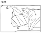
- the invention Due to a homogenization of the laser beam because of the strong focusing in one direction (first spatial direction), a high aesthetics of the structured components is possible according to the invention, so that the use of the invention is also possible in particular for structuring decorative elements (cf. FIG. 11 ).
- the invention thus enables the structuring of a wide variety of materials, so that their application in the field of tribology, the optics, the mechanics and the processing of biological samples is possible.
- large substrates for example, solar cells and OLEDs
- the extent of the laser beam in the second spatial direction is very large, compact optical working heads can be developed, which are fixed to processing stations.
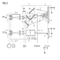
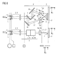
- FIGS. 2 to 8 various concrete embodiments of the device according to the invention are shown.
- the devices are in each case stationary in the Cartesian world coordinate system x, y, z, wherein the y-direction is the first spatial direction, in which the laser beam L focused in the sample volume 3 is imaged.
- the movement of the sample P takes place in each case in the first spatial direction y.
- the focusing arrangement is designed as a focusing arrangement which changes the beam cross section (in particular: with the aid of a telescope), with which a first widening of the beam cross section can already be achieved, the focusing arrangement is also referred to as widening and focusing arrangement 2 in these cases.
- the x-direction is the direction in which the laser beam in the widening and severing arrangement 4 is widened.
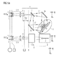
- FIGS. 5a and 5b is the sample P or its surface to be processed (unlike in the FIGS. 2 to 4c and 6 to 8 where the sample P is arranged parallel to the xy plane) parallel to the y-direction but tilted to the xy-plane, so that the second spatial direction w (parallel to the surface of the sample P) here is a direction lying in the xz plane , that is perpendicular to the y-direction direction, but does not coincide with the x-direction.
- FIGS. 2 to 8 show for each of the embodiments in each case in three rows from top to bottom the arrangement of the individual elements of the inventive devices and the flat sample P in a plane perpendicular to the first spatial direction y (first line) and in a plane parallel to the first spatial direction y (second Line) and the beam cross section or the beam shape of the laser beam at different Positions along the main optical axis of the beam (z-direction) in the third line.
- first and the second line is reversed.
- the main optical axis z is in the FIGS. 2 to 4c and 6 to 8 oriented perpendicular to the surface of the sample P.
- the laser beam L of a Q-switched, diode-pumped laser 1 (5 kHz, power 5W, pulse duration 30 ns) not shown here, first with a square aperture 11 (side length of the aperture: 5 mm) homogenized (cutting off the falling edge edges of the substantially Gaussian beam profile ) and irradiated to a arranged in the beam path after the aperture 11 telescope 9 as expansion and focusing arrangement 2.
- the telescope 9 here comprises two converging lenses.
- the ratio of the side lengths of the square beam on the beam output side of the telescope 9 and on the beam input side of the telescope 9 can be set variably, the beam extent in the two directions x and y perpendicular to the direction z set variably.
- the telescope 9 or the focal length of the output-side converging lens of the telescope is designed so that the expanded beam L beam output side of the telescope through this (taking into account the optical path lengths of the two partial beams L1 and L2 via the further optical elements 6, 7, 8 in the beam path) is focused on the surface to be processed of the sample P arranged in the sample volume 3 both in the x direction and in the y direction.
- the sample P can also be arranged in the sample volume 3 outside the location of the focusing.
- a convex cylindrical lens 6 In the beam path behind the telescope 9 is a convex cylindrical lens 6 with its focusing axis along the first spatial direction y, so arranged so that the already focused in the two directions x and y laser beam L is focused again in the second spatial direction x (where Aligning the longitudinal axis of the cylindrical lens 6, the focus in the first spatial direction y is maintained).
- the focal length f cyl of the cylindrical lens 6 is chosen so that for both partial beams (see L1 and L2 below) the ratio of the optical path length of the cylindrical lens 6 to be processed sample surface of the sample P on the one hand and the focal length f cyl on the other hand is significantly larger than 2, here is a little 12.
- a semitransparent mirror 7 (beam splitter) is arranged, with which the beam path L of the laser is split into two partial beams L1 and L2.
- the cylindrical lens 6 thus forms the laser beam L onto the semitransparent mirror 7 such that the focal point of the cylindrical lens lies in front of the semitransparent mirror 7 in the beam direction.
- the transmitted partial beam path L1 of the semitransparent mirror 7 is reflected at a first plane mirror 8a, falls on a second plane mirror 8b and is radiated from there into the sample volume 3, in which the sample P to be processed is arranged.
- the partial beam path L2 reflected on the semitransparent mirror 7 falls onto a third plane mirror 8c and is directed from there into the sample volume 3 or onto the surface of the sample P to be processed.
- the semitransparent mirror 7 (beam splitter) and the three plane mirrors 8a to 8c are positioned and aligned in the spatial space x, y, z so that the two partial beams L1 and L2 are interfering at an angle ⁇ > 0 ° (here eg 30 °) the surface of the sample P to be processed is irradiated.
- ⁇ > 0 ° here eg 30 °
- a structuring of the sample surface thus takes place.
- the two partial beam paths L1 and L2 are here - with respect to the respective central rays - from the mirror 7 to the surface of the sample P the same length (but this need not be the case).
- the widening and severing arrangement 4 thus comprises the cylindrical lens 6, the semitransparent mirror 7 and the reflection elements 8a, 8b and 8c.
- FIG. 2 (not shown) is the structure to that in FIG. 2 is structure shown identical except that the ratio of the focal length f cyl of the cylindrical lens to the optical path length from the cylindrical lens 6 to the semi-transparent mirror 7 is larger than the first In this case, the focusing of the laser radiation finally leading to further expansion in the second spatial direction x thus takes place in such a way that the focus of the cylindrical lens 6 lies behind the semitransparent mirror 7 in the beam path.
- the optical path length between the cylindrical lens 6 and the sample surface to be processed by, for example, a factor of 5 or 10, that is significantly more than a factor of 2, is greater than the focal length f cyl is also done by the cylindrical lens 6 after Focusing achieved by re-defocusing a strong expansion of the laser radiation in the second spatial direction x.
- the optical path length between cylindrical lens 6 and sample surface P - as in all other embodiments - means the mean path length (L1 + L2) / 2.
- FIG. 3 shows a second embodiment according to the invention, which basically like the in FIG. 2 shown embodiment is formed, so that only the differences will be described here.
- FIG. 3 eliminates the square aperture 11, so that the laser beam L of the laser 1 without being pruned is mapped to the telescope 9. Again, the beam diameter with the aid of the telescope (variation of the lens distance in the telescope 9) is adjustable.
- the advantage of in FIG. 3 The arrangement shown is the avoidance of intensity losses by the trimming of the beam through the diaphragm 11.
- the in FIG. 2 arrangement shown has the advantage that the intensity over the entire beam cross-section after the aperture is practically constant, so that after the optical Figure 9 . 6 .
- FIG. 4a shown third embodiment of the invention is identical to in FIG. 2 shown embodiment formed with only the difference described below:
- a telescope 9 is used instead of a two convex convergent lenses telescope, in which in the beam path first a concave scattering lens and then a convex converging lens is arranged.
- FIG. 4b shown fourth embodiment of the invention is also identical to in FIG. 2 embodiment shown with the exception of the differences described below:
- the aperture 11 In FIG. 4b deleted, as well as in FIG. 3 , the aperture 11.
- FIG. 4b instead of in FIG. 2 used widening and focusing arrangement 2 in the form of a telescope 9 a simple converging lens 12 as (the beam cross-section not changing) focusing arrangement 2.
- the beam L of the laser 1 is thus initially focused in the sample volume 3 both in the first spatial direction y and in the second spatial direction x, before the laser beam L focused in this way is guided onto the cylindrical lens 6, with which as described above, the focus in the second spatial direction x for expanding the beam path in the second spatial direction x is canceled (while maintaining the focused image in the first spatial direction y).
- FIG. 4c Fifth embodiment of the invention shown is also identical to in FIG. 2 embodiment shown with the exception of the orientation of the cylindrical lens 6 relative to the arrangement 7, 8a to 8c of the widening and severing arrangement 4.
- the longitudinal axis of the cylindrical lens 6 is thus in contrast to FIG. 2 where this longitudinal axis perpendicular to the plane defined by the two partial beams L1 and L2 plane (in FIG. 2 the xz-plane) is aligned, here parallel to the two partial beams L1 and L2 (or their central rays, see the dashed lines in Figure 4c ) plane spanned.
- the angle at which the two partial beams L1 and L2 interfere is also designated here by ⁇ .
- FIG. 5a embodiment shown is basically in its construction with in FIG. 2 shown embodiment, so again only the differences will be described.
- the beam guidance takes place after the semitransparent mirror 7 of the widening and separating arrangement 4 on the basis of only two reflection mirrors 8a and 8c, the third reflection mirror 8b in the first partial beam path L1 being omitted.
- the corresponding partial beam is thus deflected by 90 ° through exactly one reflection mirror 8 (other angles are also possible) before the respective partial beam impinges on the surface of the sample P to be processed.
- the sample surface P is here aligned parallel to the first spatial direction y, is in comparison to in FIG. 2 However, this case is no longer parallel to the xy plane, but tilted by 45 °, for example.
- the second spatial direction w in which the maximum expansion is achieved here in the interference region 5, is therefore still perpendicular to the first spatial direction y, but is now rotated by 45 ° about this first spatial direction y relative to the x axis in the counterclockwise direction ,
- FIG. 5b is basically with the in FIG. 5a identical embodiment with the exception of the focusing arrangement 2 used:
- widening and focusing arrangement 2 in the form of a telescope 9 with which a first beam expansion is already realized, is in the beam path L in front of the cylindrical lens 6 in FIG. 5b a simple converging lens 12 is arranged, with which the laser beam L is first focused in the two spatial directions y and w is shown, before then for the first widening of the beam L, the focus in the second spatial direction w is canceled by the cylindrical lens 6 again.
- FIG. 5b takes place - in contrast to the twice widening by the telescope 9 and the beam guide to the cylindrical lens 6 in figure 5a - Only a single expansion of the beam path through the beam guide behind the cylindrical lens. 6
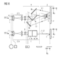
- FIG. 6 eighth embodiment of the invention shown is basically as in FIG. 2 formed embodiment, so again only the differences will be described.
- the widening and severing arrangement 4 of this embodiment has a concave, ie dispersing cylindrical lens 6 at the position of this cylindrical lens.
- the further expansion of the beam L in the second spatial direction x (while maintaining the focus F in the first spatial direction y) is thus effected here by the dispersing properties of the lens 6, the degree of renewed expansion or the expansion of the partial beams L1 and L2 in FIG Interference region 5 can be adjusted in the x-direction by the focal length of the lens 6.
- suitable displacement of the two reflection mirrors 8b and 8c against the second spatial direction x or in the second spatial direction x can be in a simple manner - as in the other embodiments.
- the interference angle ⁇ and thus the period a of the applied interference structures vary.
- the focal length of the cylindrical lens (s) 6 (or 6a, 6b, see below) and the optical path lengths in the two partial beams L1 and L2 crucial.
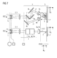
- Both embodiments use an alternative widening and severing arrangement 4, in which the semitransparent mirror 7 follows in the beam path after the telescope 9, before the transmitted partial beam path L1 via the two reflection mirrors 8a and 8b on the one hand and the reflected partial beam path L2 by means of the third reflection mirror 8c on the other hand for the realization of the interference under the interference angle ⁇ > 0 (here: 35 °) in the interference region 5 or on the sample surface P to be processed in the sample volume 3 are deflected.
- the degree of widening on the sample surface P can be varied over the focal length of the cylindrical lenses 6a and 6b which are tilted to realize the overlap angle ⁇ at precisely this angle and by the distance (in the two beam paths L1 and L2) between the respective ones Cylinder lens and the sample surface can be set almost arbitrarily.
- FIG. 8 embodiment shown is with the in FIG. 7 identical embodiment shown, but used at the location of the two concave cylindrical lenses 6a and 6b two identically formed convex cylindrical lenses (the longitudinal axis also in the y direction shows).
- the widening in the second spatial direction x is thus here by a short focal length f cyl of the two Cylindrical lenses 6a and 6b, that is achieved by an initially strong focusing and then defocusing the two partial beam paths L1 and L2 in the plane perpendicular to the first spatial direction y.
- the embodiments have 1 to 7 in the FIGS. 2 to 6 the advantage of a simpler adjustment: in the FIGS. 7 and 8th
- the two cylindrical lenses 6a and 6b must be tuned very precisely to one another in order to bring the partial beams in the overlapping region 5 parallel to the overlap.
- the in the FIGS. 1 to 5 In contrast, embodiments shown allow slight deviations in the setup of the optical elements 6, 7 and 8 without serious effect on the desired parallel overlapping in the interference region fifth
- FIGS. 2 to 8 Further optical elements, such as polarizers, can be used to optimize the beam guidance or to further adapt the structuring. For example, can be used immediately before the elements 11 and / or 2 beam homogenizers.
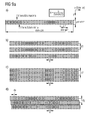
- FIG. 9a shows examples a) to d) according to the invention in the constructions of Fig. 2 to 4b and 5 to 8 by means of a pulsed laser on the surface to be applied coatable interference structures.
- the formula shown depends on the period a of the interference structures, ie the distance between adjacent lines of the interference structure, only the wavelength of the laser light 1 and the interference angle ⁇ (see, eg FIG. 2 ) between the two irradiated on the sample surface P partial beams L1 and L2.
- FIG. 9a shows, according to the invention can achieve periods a in the nm to in the micron range, focus expansions in the first spatial direction y in the micrometer to mm range and processing expansions in the second spatial direction x and w of up to 20 to 40 cm, see.
- Figure 9a-b Also, a smaller focal length (down to 0.01 cm) in this direction is conceivable.
- 9a-c can be determined by suitable choice of the feed of the sample P, for example in the y-direction (cf. FIG. 10 ) or else only in the x direction or both in the x direction and also in the y direction on the one hand and an adjusted pulse frequency of the individual laser pulses on the other hand either ( Figure 9a-b )) generate two-dimensional interference structures (increased pulse frequency compared to the sample advance leads to an increased distance of adjacent interference structures by two consecutive pulses in the y-direction) or ( Figure 9a-c)) one-dimensional, by overlapping the interference structures of temporally adjacent pulses in the y-direction generate interference structures that arise in the y direction by suitable reduction of the transport speed. (In Figure 9a-b ) the distance d1 of the structures of successive laser pulses is greater than the extent of the structures in the focusing direction y, in FIG. 9a-c) the opposite applies for the distance d2.)
- an interference pattern which is offset in the second spatial direction x can be generated by means of a sample feed, which has an additional component in the second spatial direction x.
- d y (as well as d1 and d2) denotes the spacing of adjacent structures in the y direction
- d x the additional offset of two adjacent interference structures in the direction x.
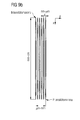
- FIG. 9b shows those with the structure Figure 4c realizable interference structures.
- the individual intensity maxima each extend parallel to the first spatial direction y and are arranged next to one another in the direction of the second spatial direction x and w
- the individual intensity maxima here along the second spatial direction x ie the widening direction (and are therefore much wider than the single in FIG. 9a shown intensity maxima)
- the first spatial direction y is thus in FIG. 9b the direction of the periodicity a of the individual maxima
- the periodicity direction is the second spatial direction x.
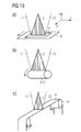
- FIG. 10a With the aid of a conveyor belt 10 only indicated here, the sample P resting on this belt can be transported in the y direction in order to structure the one- or two-dimensional interference pattern depending on the transport speed.
- FIG. 10b indicates that the sample P can also be placed on a rotating roll for patterning.
- FIG. 10c finally shows that the feed in the y-direction can also be done with a roll-to-roll transport device. In the manner shown, large components can be structured quickly.
Landscapes
- Physics & Mathematics (AREA)
- Optics & Photonics (AREA)
- Engineering & Computer Science (AREA)
- Plasma & Fusion (AREA)
- Mechanical Engineering (AREA)
- Laser Beam Processing (AREA)
- Microscoopes, Condenser (AREA)
- Coils Or Transformers For Communication (AREA)
Applications Claiming Priority (1)
| Application Number | Priority Date | Filing Date | Title |
|---|---|---|---|
| DE201110119764 DE102011119764B4 (de) | 2011-11-24 | 2011-11-24 | Vorrichtung und Verfahren zur Interferenzstrukturierung von flächigen Proben und deren Verwendung |
Publications (4)
| Publication Number | Publication Date |
|---|---|
| EP2596899A2 true EP2596899A2 (fr) | 2013-05-29 |
| EP2596899A3 EP2596899A3 (fr) | 2016-09-07 |
| EP2596899B1 EP2596899B1 (fr) | 2020-11-11 |
| EP2596899B8 EP2596899B8 (fr) | 2021-01-06 |
Family
ID=47290661
Family Applications (1)
| Application Number | Title | Priority Date | Filing Date |
|---|---|---|---|
| EP12193414.5A Active EP2596899B8 (fr) | 2011-11-24 | 2012-11-20 | Dispositif et procédé de structuration par interférences d'échantillons plats |
Country Status (4)
| Country | Link |
|---|---|
| US (1) | US9233435B2 (fr) |
| EP (1) | EP2596899B8 (fr) |
| DE (1) | DE102011119764B4 (fr) |
| ES (1) | ES2849249T3 (fr) |
Cited By (4)
| Publication number | Priority date | Publication date | Assignee | Title |
|---|---|---|---|---|
| WO2013186179A3 (fr) * | 2012-06-11 | 2014-02-06 | Fraunhofer-Gesellschaft zur Förderung der angewandten Forschung e.V. | Dispositif et procédé de structuration interférentielle d'échantillons et échantillons ainsi structurés |
| WO2020221499A1 (fr) * | 2019-04-30 | 2020-11-05 | Fraunhofer-Gesellschaft zur Förderung der angewandten Forschung e.V. | Agencement pour modifier des surfaces de composants métalliques |
| WO2021205036A1 (fr) | 2020-04-11 | 2021-10-14 | Surfuncion Gmbh | Dispositif optique, procédé et utilisation |
| LU102920B1 (de) * | 2022-03-31 | 2023-10-02 | Fusion Bionic Gmbh | Vorrichtung und Verfahren zur Laserinterferenzstrukturierung von Substraten mit periodischen Punktstrukturen für Antireflexionseigenschaften |
Families Citing this family (12)
| Publication number | Priority date | Publication date | Assignee | Title |
|---|---|---|---|---|
| TWI612712B (zh) * | 2012-10-25 | 2018-01-21 | 應用材料股份有限公司 | 繞射光學元件及用於圖案化薄膜電化學元件的方法 |
| WO2016004511A1 (fr) * | 2014-07-11 | 2016-01-14 | National Research Council Of Canada | Formation d'un réseau optique avec un appareil produisant un motif d'interférence réglable |
| DE102015214960B4 (de) | 2015-08-05 | 2018-03-01 | Fraunhofer-Gesellschaft zur Förderung der angewandten Forschung e.V. | Vorrichtung und Verfahren zur Interferenzstrukturierung einer Oberfläche einer flächigen Probe und deren Verwendung |
| TWI561939B (en) * | 2015-11-03 | 2016-12-11 | Univ Nat Sun Yat Sen | Interference lithography device |
| DE102017206968B4 (de) * | 2017-04-26 | 2019-10-10 | 4Jet Microtech Gmbh & Co. Kg | Verfahren und Vorrichtung zum Herstellen von Riblets |
| DE102017211511A1 (de) | 2017-07-06 | 2019-01-10 | Technische Universität Dresden | Laserstrukturierte Elektroden- und Werkstückoberflächen für das Widerstandspunktschweißen |
| DE102018200036B3 (de) | 2018-01-03 | 2019-01-17 | Fraunhofer-Gesellschaft zur Förderung der angewandten Forschung e.V. | Optische Anordnung zur direkten Laserinterferenzstrukturierung |
| DE102018105254B4 (de) | 2018-03-07 | 2020-06-04 | Fraunhofer-Gesellschaft zur Förderung der angewandten Forschung e.V. | Verfahren und Vorrichtung zur Bearbeitung mittels interferierender Laserstrahlung |
| KR20240031352A (ko) * | 2021-07-03 | 2024-03-07 | 퓨전 바이오닉 게엠베하 | 반사 방지 속성을 위한 주기적인 도트 구조를 갖는 기판의 레이저 간섭 구조화를 위한 장치 및 방법 |
| DE102022121616A1 (de) * | 2022-08-26 | 2024-02-29 | Trumpf Laser Gmbh | Lasersystem und Verfahren zur Laserbearbeitung eines Werkstücks |
| DE102023201553A1 (de) * | 2023-02-22 | 2024-08-22 | 3D-Micromac Ag | Verfahren und System zur Herstellung mikroelektronischer Komponenten mit Schichtaufbau |
| WO2025168703A1 (fr) * | 2024-02-09 | 2025-08-14 | SurFunction GmbH | Dispositif optique, système optique et utilisation du dispositif optique pour usiner un échantillon au moyen de faisceaux laser interférents |
Citations (3)
| Publication number | Priority date | Publication date | Assignee | Title |
|---|---|---|---|---|
| US20030035219A1 (en) | 2001-08-17 | 2003-02-20 | Semiconductor Energy Labporatory Co., Ltd. | Laser, irradiation apparatus, laser irradiation method, and method for manufacturing semiconductor device |
| JP2006110587A (ja) | 2004-10-14 | 2006-04-27 | Canon Inc | レーザー干渉加工方法および装置 |
| WO2011072663A2 (fr) | 2009-12-18 | 2011-06-23 | Fraunhofer-Gesellschaft zur Förderung der angewandten Forschung e.V. | Procédé de production d'un composant à couches minces et composant à couches minces ainsi obtenu |
Family Cites Families (5)
| Publication number | Priority date | Publication date | Assignee | Title |
|---|---|---|---|---|
| US5534970A (en) * | 1993-06-11 | 1996-07-09 | Nikon Corporation | Scanning exposure apparatus |
| JP4065468B2 (ja) * | 1998-06-30 | 2008-03-26 | キヤノン株式会社 | 露光装置及びこれを用いたデバイスの製造方法 |
| US7005235B2 (en) * | 2002-12-04 | 2006-02-28 | Taiwan Semiconductor Manufacturing Co., Ltd. | Method and systems to print contact hole patterns |
| DE102006032053B4 (de) * | 2006-07-10 | 2009-10-08 | Laser-Laboratorium Göttingen eV | Oberflächenmodifikationsverfahren und- vorrichtung |
| GB2460648A (en) * | 2008-06-03 | 2009-12-09 | M Solv Ltd | Method and apparatus for laser focal spot size control |
-
2011
- 2011-11-24 DE DE201110119764 patent/DE102011119764B4/de not_active Expired - Fee Related
-
2012
- 2012-11-20 EP EP12193414.5A patent/EP2596899B8/fr active Active
- 2012-11-20 ES ES12193414T patent/ES2849249T3/es active Active
- 2012-11-26 US US13/684,915 patent/US9233435B2/en active Active
Patent Citations (3)
| Publication number | Priority date | Publication date | Assignee | Title |
|---|---|---|---|---|
| US20030035219A1 (en) | 2001-08-17 | 2003-02-20 | Semiconductor Energy Labporatory Co., Ltd. | Laser, irradiation apparatus, laser irradiation method, and method for manufacturing semiconductor device |
| JP2006110587A (ja) | 2004-10-14 | 2006-04-27 | Canon Inc | レーザー干渉加工方法および装置 |
| WO2011072663A2 (fr) | 2009-12-18 | 2011-06-23 | Fraunhofer-Gesellschaft zur Förderung der angewandten Forschung e.V. | Procédé de production d'un composant à couches minces et composant à couches minces ainsi obtenu |
Non-Patent Citations (3)
| Title |
|---|
| N. RIZVI ET AL.: "Production of Submicrometer Period Bragg Gratings in Optical Fibers Using Wavefront Division With a Bi-Prism and an Excemer Laser Source", APPL. PHYS. LETT., vol. 67, no. 6, pages 7,739 |
| R. SIDHARTHAN ET AL.: "Periodic Patterning Using Multi-Facet Prism-Based Laser Interference Lithography", LASER PHYSICS, vol. 19, 2009 |
| T. KONDO ET AL.: "Femtosecond laser interference technique with diffractive beam splitter for fabrication of three-dimensional photonic crystals", APPLIED PHYSICS LETTERS, vol. 79, 2001, pages 725 - 727, XP012029966, DOI: doi:10.1063/1.1391232 |
Cited By (5)
| Publication number | Priority date | Publication date | Assignee | Title |
|---|---|---|---|---|
| WO2013186179A3 (fr) * | 2012-06-11 | 2014-02-06 | Fraunhofer-Gesellschaft zur Förderung der angewandten Forschung e.V. | Dispositif et procédé de structuration interférentielle d'échantillons et échantillons ainsi structurés |
| WO2020221499A1 (fr) * | 2019-04-30 | 2020-11-05 | Fraunhofer-Gesellschaft zur Förderung der angewandten Forschung e.V. | Agencement pour modifier des surfaces de composants métalliques |
| WO2021205036A1 (fr) | 2020-04-11 | 2021-10-14 | Surfuncion Gmbh | Dispositif optique, procédé et utilisation |
| DE102020204656A1 (de) | 2020-04-11 | 2021-10-14 | DLIP UG (haftungsbeschränkt) | Anordnung optischer Elemente zur Ausbildung von großflächigen Strukturen mit linienförmigen Strukturelementen |
| LU102920B1 (de) * | 2022-03-31 | 2023-10-02 | Fusion Bionic Gmbh | Vorrichtung und Verfahren zur Laserinterferenzstrukturierung von Substraten mit periodischen Punktstrukturen für Antireflexionseigenschaften |
Also Published As
| Publication number | Publication date |
|---|---|
| EP2596899B1 (fr) | 2020-11-11 |
| EP2596899A3 (fr) | 2016-09-07 |
| EP2596899B8 (fr) | 2021-01-06 |
| ES2849249T3 (es) | 2021-08-17 |
| US20130153553A1 (en) | 2013-06-20 |
| DE102011119764A1 (de) | 2013-05-29 |
| DE102011119764B4 (de) | 2015-04-30 |
| US9233435B2 (en) | 2016-01-12 |
Similar Documents
| Publication | Publication Date | Title |
|---|---|---|
| DE102011119764B4 (de) | Vorrichtung und Verfahren zur Interferenzstrukturierung von flächigen Proben und deren Verwendung | |
| DE102012011343B4 (de) | Vorrichtung zur Interferenzstrukturierung von Proben | |
| EP2673106B1 (fr) | Dispositif, sytème et méthode pour la texturation de pièces plates par interférences lumineuses | |
| EP3094444B1 (fr) | Appareil et procédé pour traiter une surface par laser | |
| DE102020207715A1 (de) | Bearbeitungsoptik, Laserbearbeitungsvorrichtung und Verfahren zur Laserbearbeitung | |
| DE102008033358B4 (de) | Vorrichtung und Verfahren zur Umverteilung des Strahlparameter-Produktes eines Laserstrahls | |
| EP4058233A1 (fr) | Procédé de traitement laser d'une pièce à usiner, système de traitement optique et dispositif de traitement laser | |
| EP2143518B1 (fr) | Dispositif de traitement laser et procédé de traitement laser doté d'un point focal double ou multiple à l'aide d'un scanner galvanométrique | |
| EP3932609B1 (fr) | Dispositif d'usinage laser des matériaux avec deux unitées de décalage parallèle du faisceau laser | |
| EP2547486B1 (fr) | Procédé et dispositif de modification périodique spatiale d'une surface de substrat à l'aide d'une optique f-theta telecentrique | |
| EP3854513A1 (fr) | Système de formation d'un faisceau optique asymétrique | |
| DE102014106472A1 (de) | Verfahren zum Strahlungsritzen eines Halbleitersubstrats | |
| WO2022122251A1 (fr) | Usinage au laser d'un matériau à l'aide d'un élément filtrant à gradient | |
| DE102008000306B4 (de) | Verfahren und Vorrichtung zum Laserschneiden | |
| DE102006032053B4 (de) | Oberflächenmodifikationsverfahren und- vorrichtung | |
| DE102012004312A1 (de) | Verfahren und Vorrichtung zur schnellen konzentrischen Ablenkung mehrerer Lichtstrahlen mit einstellbarem Winkel um die Systemachse | |
| EP0683007A1 (fr) | Dispositif d'usinage | |
| WO2022033923A1 (fr) | Appareil pour générer une raie laser définie sur un plan de travail | |
| DE102022204685B3 (de) | Optik zur Erzeugung eines linearen Fokus, Vorrichtung und Verfahren zur Bearbeitung eines Werkstücks | |
| DE102012012883B4 (de) | Laserbearbeitungsvorrichtung zur Laserbearbeitung eines Ausgangssubstrats für die Herstellung von Solarzellen | |
| DE102012101643A1 (de) | Vorrichtung und Verfahren zum Ablenken von elektro-magnetischer Strahlung, Vorrichtung und Verfahren zum Bestrahlen eines Körpers | |
| DE102024209847A1 (de) | Verfahren und Vorrichtung zur Erzeugung von Materialabtragungsbereichen in einem Glasobjekt | |
| DE102021121230A1 (de) | Optische Anordnung und Lasersystem |
Legal Events
| Date | Code | Title | Description |
|---|---|---|---|
| PUAI | Public reference made under article 153(3) epc to a published international application that has entered the european phase |
Free format text: ORIGINAL CODE: 0009012 |
|
| AK | Designated contracting states |
Kind code of ref document: A2 Designated state(s): AL AT BE BG CH CY CZ DE DK EE ES FI FR GB GR HR HU IE IS IT LI LT LU LV MC MK MT NL NO PL PT RO RS SE SI SK SM TR |
|
| AX | Request for extension of the european patent |
Extension state: BA ME |
|
| RIN1 | Information on inventor provided before grant (corrected) |
Inventor name: LASAGNI, ANDRES FABIAN |
|
| PUAL | Search report despatched |
Free format text: ORIGINAL CODE: 0009013 |
|
| AK | Designated contracting states |
Kind code of ref document: A3 Designated state(s): AL AT BE BG CH CY CZ DE DK EE ES FI FR GB GR HR HU IE IS IT LI LT LU LV MC MK MT NL NO PL PT RO RS SE SI SK SM TR |
|
| AX | Request for extension of the european patent |
Extension state: BA ME |
|
| RIC1 | Information provided on ipc code assigned before grant |
Ipc: B23K 26/067 20060101ALI20160801BHEP Ipc: B23K 26/06 20060101AFI20160801BHEP Ipc: B23K 26/073 20060101ALI20160801BHEP Ipc: B23K 26/00 20140101ALI20160801BHEP |
|
| STAA | Information on the status of an ep patent application or granted ep patent |
Free format text: STATUS: REQUEST FOR EXAMINATION WAS MADE |
|
| 17P | Request for examination filed |
Effective date: 20170228 |
|
| RBV | Designated contracting states (corrected) |
Designated state(s): AL AT BE BG CH CY CZ DE DK EE ES FI FR GB GR HR HU IE IS IT LI LT LU LV MC MK MT NL NO PL PT RO RS SE SI SK SM TR |
|
| STAA | Information on the status of an ep patent application or granted ep patent |
Free format text: STATUS: EXAMINATION IS IN PROGRESS |
|
| 17Q | First examination report despatched |
Effective date: 20180813 |
|
| GRAP | Despatch of communication of intention to grant a patent |
Free format text: ORIGINAL CODE: EPIDOSNIGR1 |
|
| STAA | Information on the status of an ep patent application or granted ep patent |
Free format text: STATUS: GRANT OF PATENT IS INTENDED |
|
| INTG | Intention to grant announced |
Effective date: 20200325 |
|
| GRAJ | Information related to disapproval of communication of intention to grant by the applicant or resumption of examination proceedings by the epo deleted |
Free format text: ORIGINAL CODE: EPIDOSDIGR1 |
|
| STAA | Information on the status of an ep patent application or granted ep patent |
Free format text: STATUS: EXAMINATION IS IN PROGRESS |
|
| GRAP | Despatch of communication of intention to grant a patent |
Free format text: ORIGINAL CODE: EPIDOSNIGR1 |
|
| INTC | Intention to grant announced (deleted) | ||
| STAA | Information on the status of an ep patent application or granted ep patent |
Free format text: STATUS: GRANT OF PATENT IS INTENDED |
|
| INTG | Intention to grant announced |
Effective date: 20200604 |
|
| GRAS | Grant fee paid |
Free format text: ORIGINAL CODE: EPIDOSNIGR3 |
|
| GRAA | (expected) grant |
Free format text: ORIGINAL CODE: 0009210 |
|
| STAA | Information on the status of an ep patent application or granted ep patent |
Free format text: STATUS: THE PATENT HAS BEEN GRANTED |
|
| REG | Reference to a national code |
Ref country code: DE Ref legal event code: R108 Ref document number: 502012016469 Country of ref document: DE |
|
| AK | Designated contracting states |
Kind code of ref document: B1 Designated state(s): AL AT BE BG CH CY CZ DE DK EE ES FI FR GB GR HR HU IE IS IT LI LT LU LV MC MK MT NL NO PL PT RO RS SE SI SK SM TR |
|
| REG | Reference to a national code |
Ref country code: GB Ref legal event code: FG4D Free format text: NOT ENGLISH |
|
| REG | Reference to a national code |
Ref country code: CH Ref legal event code: EP |
|
| REG | Reference to a national code |
Ref country code: AT Ref legal event code: REF Ref document number: 1332987 Country of ref document: AT Kind code of ref document: T Effective date: 20201115 |
|
| REG | Reference to a national code |
Ref country code: DE Ref legal event code: R096 Ref document number: 502012016469 Country of ref document: DE |
|
| RBV | Designated contracting states (corrected) |
Designated state(s): AL AT BE BG CH CY CZ DK EE ES FI FR GB GR HR HU IE IS IT LI LT LU LV MC MK MT NL NO PL PT RO RS SE SI SK SM TR |
|
| REG | Reference to a national code |
Ref country code: IE Ref legal event code: FG4D Free format text: LANGUAGE OF EP DOCUMENT: GERMAN |
|
| REG | Reference to a national code |
Ref country code: CH Ref legal event code: PK Free format text: BERICHTIGUNG B8 |
|
| REG | Reference to a national code |
Ref country code: DE Ref legal event code: R107 Ref document number: 502012016469 Country of ref document: DE |
|
| REG | Reference to a national code |
Ref country code: FI Ref legal event code: FGE |
|
| REG | Reference to a national code |
Ref country code: NL Ref legal event code: FP |
|
| PG25 | Lapsed in a contracting state [announced via postgrant information from national office to epo] |
Ref country code: GR Free format text: LAPSE BECAUSE OF FAILURE TO SUBMIT A TRANSLATION OF THE DESCRIPTION OR TO PAY THE FEE WITHIN THE PRESCRIBED TIME-LIMIT Effective date: 20210212 Ref country code: NO Free format text: LAPSE BECAUSE OF FAILURE TO SUBMIT A TRANSLATION OF THE DESCRIPTION OR TO PAY THE FEE WITHIN THE PRESCRIBED TIME-LIMIT Effective date: 20210211 Ref country code: PT Free format text: LAPSE BECAUSE OF FAILURE TO SUBMIT A TRANSLATION OF THE DESCRIPTION OR TO PAY THE FEE WITHIN THE PRESCRIBED TIME-LIMIT Effective date: 20210311 Ref country code: RS Free format text: LAPSE BECAUSE OF FAILURE TO SUBMIT A TRANSLATION OF THE DESCRIPTION OR TO PAY THE FEE WITHIN THE PRESCRIBED TIME-LIMIT Effective date: 20201111 |
|
| PG25 | Lapsed in a contracting state [announced via postgrant information from national office to epo] |
Ref country code: LV Free format text: LAPSE BECAUSE OF FAILURE TO SUBMIT A TRANSLATION OF THE DESCRIPTION OR TO PAY THE FEE WITHIN THE PRESCRIBED TIME-LIMIT Effective date: 20201111 Ref country code: PL Free format text: LAPSE BECAUSE OF FAILURE TO SUBMIT A TRANSLATION OF THE DESCRIPTION OR TO PAY THE FEE WITHIN THE PRESCRIBED TIME-LIMIT Effective date: 20201111 Ref country code: IS Free format text: LAPSE BECAUSE OF FAILURE TO SUBMIT A TRANSLATION OF THE DESCRIPTION OR TO PAY THE FEE WITHIN THE PRESCRIBED TIME-LIMIT Effective date: 20210311 Ref country code: SE Free format text: LAPSE BECAUSE OF FAILURE TO SUBMIT A TRANSLATION OF THE DESCRIPTION OR TO PAY THE FEE WITHIN THE PRESCRIBED TIME-LIMIT Effective date: 20201111 Ref country code: BG Free format text: LAPSE BECAUSE OF FAILURE TO SUBMIT A TRANSLATION OF THE DESCRIPTION OR TO PAY THE FEE WITHIN THE PRESCRIBED TIME-LIMIT Effective date: 20210211 |
|
| REG | Reference to a national code |
Ref country code: LT Ref legal event code: MG9D |
|
| PG25 | Lapsed in a contracting state [announced via postgrant information from national office to epo] |
Ref country code: HR Free format text: LAPSE BECAUSE OF FAILURE TO SUBMIT A TRANSLATION OF THE DESCRIPTION OR TO PAY THE FEE WITHIN THE PRESCRIBED TIME-LIMIT Effective date: 20201111 |
|
| REG | Reference to a national code |
Ref country code: CH Ref legal event code: PL |
|
| PG25 | Lapsed in a contracting state [announced via postgrant information from national office to epo] |
Ref country code: SM Free format text: LAPSE BECAUSE OF FAILURE TO SUBMIT A TRANSLATION OF THE DESCRIPTION OR TO PAY THE FEE WITHIN THE PRESCRIBED TIME-LIMIT Effective date: 20201111 Ref country code: CZ Free format text: LAPSE BECAUSE OF FAILURE TO SUBMIT A TRANSLATION OF THE DESCRIPTION OR TO PAY THE FEE WITHIN THE PRESCRIBED TIME-LIMIT Effective date: 20201111 Ref country code: EE Free format text: LAPSE BECAUSE OF FAILURE TO SUBMIT A TRANSLATION OF THE DESCRIPTION OR TO PAY THE FEE WITHIN THE PRESCRIBED TIME-LIMIT Effective date: 20201111 Ref country code: RO Free format text: LAPSE BECAUSE OF FAILURE TO SUBMIT A TRANSLATION OF THE DESCRIPTION OR TO PAY THE FEE WITHIN THE PRESCRIBED TIME-LIMIT Effective date: 20201111 Ref country code: SK Free format text: LAPSE BECAUSE OF FAILURE TO SUBMIT A TRANSLATION OF THE DESCRIPTION OR TO PAY THE FEE WITHIN THE PRESCRIBED TIME-LIMIT Effective date: 20201111 Ref country code: LT Free format text: LAPSE BECAUSE OF FAILURE TO SUBMIT A TRANSLATION OF THE DESCRIPTION OR TO PAY THE FEE WITHIN THE PRESCRIBED TIME-LIMIT Effective date: 20201111 Ref country code: LU Free format text: LAPSE BECAUSE OF NON-PAYMENT OF DUE FEES Effective date: 20201120 |
|
| REG | Reference to a national code |
Ref country code: BE Ref legal event code: MM Effective date: 20201130 |
|
| REG | Reference to a national code |
Ref country code: ES Ref legal event code: FG2A Ref document number: 2849249 Country of ref document: ES Kind code of ref document: T3 Effective date: 20210817 |
|
| PG25 | Lapsed in a contracting state [announced via postgrant information from national office to epo] |
Ref country code: MC Free format text: LAPSE BECAUSE OF FAILURE TO SUBMIT A TRANSLATION OF THE DESCRIPTION OR TO PAY THE FEE WITHIN THE PRESCRIBED TIME-LIMIT Effective date: 20201111 Ref country code: CH Free format text: LAPSE BECAUSE OF NON-PAYMENT OF DUE FEES Effective date: 20201130 Ref country code: DK Free format text: LAPSE BECAUSE OF FAILURE TO SUBMIT A TRANSLATION OF THE DESCRIPTION OR TO PAY THE FEE WITHIN THE PRESCRIBED TIME-LIMIT Effective date: 20201111 Ref country code: LI Free format text: LAPSE BECAUSE OF NON-PAYMENT OF DUE FEES Effective date: 20201130 |
|
| PLBE | No opposition filed within time limit |
Free format text: ORIGINAL CODE: 0009261 |
|
| STAA | Information on the status of an ep patent application or granted ep patent |
Free format text: STATUS: NO OPPOSITION FILED WITHIN TIME LIMIT |
|
| 26N | No opposition filed |
Effective date: 20210812 |
|
| GBPC | Gb: european patent ceased through non-payment of renewal fee |
Effective date: 20210211 |
|
| PG25 | Lapsed in a contracting state [announced via postgrant information from national office to epo] |
Ref country code: AL Free format text: LAPSE BECAUSE OF FAILURE TO SUBMIT A TRANSLATION OF THE DESCRIPTION OR TO PAY THE FEE WITHIN THE PRESCRIBED TIME-LIMIT Effective date: 20201111 Ref country code: IE Free format text: LAPSE BECAUSE OF NON-PAYMENT OF DUE FEES Effective date: 20201120 |
|
| PG25 | Lapsed in a contracting state [announced via postgrant information from national office to epo] |
Ref country code: SI Free format text: LAPSE BECAUSE OF FAILURE TO SUBMIT A TRANSLATION OF THE DESCRIPTION OR TO PAY THE FEE WITHIN THE PRESCRIBED TIME-LIMIT Effective date: 20201111 |
|
| REG | Reference to a national code |
Ref country code: AT Ref legal event code: MM01 Ref document number: 1332987 Country of ref document: AT Kind code of ref document: T Effective date: 20201120 |
|
| PG25 | Lapsed in a contracting state [announced via postgrant information from national office to epo] |
Ref country code: GB Free format text: LAPSE BECAUSE OF NON-PAYMENT OF DUE FEES Effective date: 20210211 Ref country code: AT Free format text: LAPSE BECAUSE OF NON-PAYMENT OF DUE FEES Effective date: 20201120 |
|
| PG25 | Lapsed in a contracting state [announced via postgrant information from national office to epo] |
Ref country code: IS Free format text: LAPSE BECAUSE OF FAILURE TO SUBMIT A TRANSLATION OF THE DESCRIPTION OR TO PAY THE FEE WITHIN THE PRESCRIBED TIME-LIMIT Effective date: 20210311 Ref country code: TR Free format text: LAPSE BECAUSE OF FAILURE TO SUBMIT A TRANSLATION OF THE DESCRIPTION OR TO PAY THE FEE WITHIN THE PRESCRIBED TIME-LIMIT Effective date: 20201111 Ref country code: MT Free format text: LAPSE BECAUSE OF FAILURE TO SUBMIT A TRANSLATION OF THE DESCRIPTION OR TO PAY THE FEE WITHIN THE PRESCRIBED TIME-LIMIT Effective date: 20201111 Ref country code: CY Free format text: LAPSE BECAUSE OF FAILURE TO SUBMIT A TRANSLATION OF THE DESCRIPTION OR TO PAY THE FEE WITHIN THE PRESCRIBED TIME-LIMIT Effective date: 20201111 |
|
| PG25 | Lapsed in a contracting state [announced via postgrant information from national office to epo] |
Ref country code: MK Free format text: LAPSE BECAUSE OF FAILURE TO SUBMIT A TRANSLATION OF THE DESCRIPTION OR TO PAY THE FEE WITHIN THE PRESCRIBED TIME-LIMIT Effective date: 20201111 |
|
| PG25 | Lapsed in a contracting state [announced via postgrant information from national office to epo] |
Ref country code: BE Free format text: LAPSE BECAUSE OF NON-PAYMENT OF DUE FEES Effective date: 20201130 |
|
| PGFP | Annual fee paid to national office [announced via postgrant information from national office to epo] |
Ref country code: NL Payment date: 20221118 Year of fee payment: 11 Ref country code: IT Payment date: 20221130 Year of fee payment: 11 Ref country code: FR Payment date: 20221118 Year of fee payment: 11 Ref country code: FI Payment date: 20221117 Year of fee payment: 11 Ref country code: ES Payment date: 20221216 Year of fee payment: 11 |
|
| REG | Reference to a national code |
Ref country code: NL Ref legal event code: MM Effective date: 20231201 |
|
| PG25 | Lapsed in a contracting state [announced via postgrant information from national office to epo] |
Ref country code: FI Free format text: LAPSE BECAUSE OF NON-PAYMENT OF DUE FEES Effective date: 20231120 |
|
| PG25 | Lapsed in a contracting state [announced via postgrant information from national office to epo] |
Ref country code: NL Free format text: LAPSE BECAUSE OF NON-PAYMENT OF DUE FEES Effective date: 20231201 |
|
| PG25 | Lapsed in a contracting state [announced via postgrant information from national office to epo] |
Ref country code: NL Free format text: LAPSE BECAUSE OF NON-PAYMENT OF DUE FEES Effective date: 20231201 |
|
| PG25 | Lapsed in a contracting state [announced via postgrant information from national office to epo] |
Ref country code: FR Free format text: LAPSE BECAUSE OF NON-PAYMENT OF DUE FEES Effective date: 20231130 |
|
| PG25 | Lapsed in a contracting state [announced via postgrant information from national office to epo] |
Ref country code: FR Free format text: LAPSE BECAUSE OF NON-PAYMENT OF DUE FEES Effective date: 20231130 |
|
| P01 | Opt-out of the competence of the unified patent court (upc) registered |
Free format text: CASE NUMBER: UPC_APP_326395/2023 Effective date: 20230524 |
|
| PG25 | Lapsed in a contracting state [announced via postgrant information from national office to epo] |
Ref country code: IT Free format text: LAPSE BECAUSE OF NON-PAYMENT OF DUE FEES Effective date: 20231120 |
|
| PG25 | Lapsed in a contracting state [announced via postgrant information from national office to epo] |
Ref country code: IT Free format text: LAPSE BECAUSE OF NON-PAYMENT OF DUE FEES Effective date: 20231120 |
|
| REG | Reference to a national code |
Ref country code: ES Ref legal event code: FD2A Effective date: 20250103 |
|
| PG25 | Lapsed in a contracting state [announced via postgrant information from national office to epo] |
Ref country code: ES Free format text: LAPSE BECAUSE OF NON-PAYMENT OF DUE FEES Effective date: 20231121 |
|
| PG25 | Lapsed in a contracting state [announced via postgrant information from national office to epo] |
Ref country code: ES Free format text: LAPSE BECAUSE OF NON-PAYMENT OF DUE FEES Effective date: 20231121 |