EP2597267A1 - Installation comportant des modules de turbine à vapeur avec efficacité optimisée - Google Patents
Installation comportant des modules de turbine à vapeur avec efficacité optimisée Download PDFInfo
- Publication number
- EP2597267A1 EP2597267A1 EP12185711.4A EP12185711A EP2597267A1 EP 2597267 A1 EP2597267 A1 EP 2597267A1 EP 12185711 A EP12185711 A EP 12185711A EP 2597267 A1 EP2597267 A1 EP 2597267A1
- Authority
- EP
- European Patent Office
- Prior art keywords
- module
- pressure
- steam
- chamber
- installation
- Prior art date
- Legal status (The legal status is an assumption and is not a legal conclusion. Google has not performed a legal analysis and makes no representation as to the accuracy of the status listed.)
- Withdrawn
Links
Images


Classifications
-
- F—MECHANICAL ENGINEERING; LIGHTING; HEATING; WEAPONS; BLASTING
- F01—MACHINES OR ENGINES IN GENERAL; ENGINE PLANTS IN GENERAL; STEAM ENGINES
- F01D—NON-POSITIVE DISPLACEMENT MACHINES OR ENGINES, e.g. STEAM TURBINES
- F01D11/00—Preventing or minimising internal leakage of working-fluid, e.g. between stages
-
- F—MECHANICAL ENGINEERING; LIGHTING; HEATING; WEAPONS; BLASTING
- F01—MACHINES OR ENGINES IN GENERAL; ENGINE PLANTS IN GENERAL; STEAM ENGINES
- F01D—NON-POSITIVE DISPLACEMENT MACHINES OR ENGINES, e.g. STEAM TURBINES
- F01D11/00—Preventing or minimising internal leakage of working-fluid, e.g. between stages
- F01D11/02—Preventing or minimising internal leakage of working-fluid, e.g. between stages by non-contact sealings, e.g. of labyrinth type
- F01D11/04—Preventing or minimising internal leakage of working-fluid, e.g. between stages by non-contact sealings, e.g. of labyrinth type using sealing fluid, e.g. steam
- F01D11/06—Control thereof
-
- F—MECHANICAL ENGINEERING; LIGHTING; HEATING; WEAPONS; BLASTING
- F01—MACHINES OR ENGINES IN GENERAL; ENGINE PLANTS IN GENERAL; STEAM ENGINES
- F01K—STEAM ENGINE PLANTS; STEAM ACCUMULATORS; ENGINE PLANTS NOT OTHERWISE PROVIDED FOR; ENGINES USING SPECIAL WORKING FLUIDS OR CYCLES
- F01K9/00—Plants characterised by condensers arranged or modified to co-operate with the engines
-
- F—MECHANICAL ENGINEERING; LIGHTING; HEATING; WEAPONS; BLASTING
- F05—INDEXING SCHEMES RELATING TO ENGINES OR PUMPS IN VARIOUS SUBCLASSES OF CLASSES F01-F04
- F05D—INDEXING SCHEME FOR ASPECTS RELATING TO NON-POSITIVE-DISPLACEMENT MACHINES OR ENGINES, GAS-TURBINES OR JET-PROPULSION PLANTS
- F05D2220/00—Application
- F05D2220/30—Application in turbines
- F05D2220/31—Application in turbines in steam turbines
Definitions
- the present invention relates to the field of nuclear installations comprising steam turbine modules.
- This type of installation is generally composed of a plurality of turbine modules, including a high pressure module, one or more low pressure modules, and an intermediate medium pressure module. Each module can be configured in a single flow or double flow arrangement.
- the installation is intended to generate electricity by means of an alternator driven by the turbine modules.
- the installation may operate on fossil fuel or nuclear power.
- An installation of the known type has a rotating turbine shaft connecting the rotors of the various modules. Each rotor is housed in a casing. Sealing devices are positioned between the turbine shaft and each of the casings. A leak of steam occurs at the sealing devices. In the prior art, the leakage occurring at the sealing device of the high pressure module is collected and sent to a leak collection system.
- Devices of this type have, notably, the disadvantage of having a considerable ingress of air into the steam cycle through the low pressure modules, because the latter are at a lower pressure than the atmosphere. This ingress of air leads to a change in the thermodynamic characteristics of the steam, thus reducing efficiency. Moreover, since the steam working in the low pressure modules is close to saturation, this ingress of air may also lead to the appearance of water droplets which may damage a condenser located at the outlet of the low pressure module. According to the prior art, one solution to this problem is to create a live steam feed in the low pressure modules, said live steam being taken off at the source, i.e. in the steam generator. This does indeed limit the ingress of air, but has the drawback of limiting the work of the live steam in the steam flow.
- the invention is intended to overcome some or all of these drawbacks and improve the efficiency of the installation by optimizing the steam cycle.
- the installation comprises a high pressure steam turbine module, a medium pressure steam turbine module, and at least one low pressure steam turbine module, sealing devices being positioned between a rotating turbine shaft and the corresponding casings of the various steam turbine modules, each of the modules comprising a main chamber in which the turbine is housed, the installation further comprising:
- the installation comprises a third collection chamber positioned between the main chamber of the high pressure module and the first collection chamber casing in such a way that the leaks of steam from the high pressure module through its sealing device are collected and said leaks are directed via a conduit toward the main chamber of the medium pressure module or toward an inlet of the main chamber of the low pressure module.
- the third collection chamber is kept at a pressure level between the pressure inside the high pressure module casing and the pressure in the first collection chamber. This arrangement enables the recovery of steam leaks to be optimized at the sealing device of the high pressure module.
- each sealing device of the various steam turbine modules has a fourth collection chamber positioned in the casing of the module concerned, said fourth collection chamber having a pressure lower than atmospheric pressure, so as to collect not only the leaks of steam leaving said module through its sealing device but also any air entering from outside the casing concerned. Because of this characteristic, the ingress of air into the various modules and the leakage of steam toward the outside are both effectively prevented.
- the term "inside” applied to a module signifies the space within the casing
- the term “outside” signifies the external space extending beyond the limit defined by the casing of said module.
- each fourth collection chamber is connected by a conduit to a second circuit at a lower pressure than atmospheric pressure. Because of this characteristic, the air and steam collected in the fourth chambers can be effectively sucked out and removed.
- the first circuit has pressure control means which keep its pressure at a level above atmospheric pressure. Because of this characteristic, steam can be transferred from the first and/or second chambers toward the injection chamber.
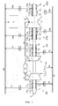
- FIG. 1 shows an installation according to the invention, with its steam circuits.
- the installation comprises a high pressure steam turbine module 1, a medium pressure steam turbine module 2, and one or more low pressure steam turbine modules 3.
- the high pressure turbine is fed with live steam, in other words with steam from a steam generator 40, such as a nuclear powered steam generator.
- the steam leaving the high pressure module 1 is guided by a conduit 41 through a drier/superheater 42 toward the inlet of the medium pressure module 2.
- the steam leaving the medium pressure module 2 is guided by a conduit 43 toward the inlet of the low pressure module 3.
- the outlet of the low pressure module 3 is connected to a steam condenser 6.
- the rotors of the various modules 1, 2, 3 are interconnected to form a rotating turbine shaft 5.
- Each rotor is housed in a casing 10, 20, 30 belonging to the modules 1, 2, 3 respectively, and more precisely in respective main chambers 1', 2', 3' of said modules 1, 2, 3 in which the turbine operates.
- Sealing devices 100, 200, 300a, 300b are positioned between the turbine shaft 5 and the casings 10, 20, 30 of the various modules.
- the sealing device 100 of the high pressure module 1 comprises three sealing gaskets, namely a first gasket 11 on the end nearest the module 1, a third gasket 13 on the end outside the module 1, and a second gasket 12 between the first 11 and third 13 gaskets.
- the first gasket 11 causes a leak F11 of steam from the main chamber 1' of the high pressure module 1 toward a first collection chamber C1 positioned in the casing 10 of the high pressure module 1.
- the first collection chamber C1 is connected by a conduit 15 to a first circuit 61.
- a fourth collection chamber C4 is positioned in the casing 10 of the high pressure module 1 between the second and third gaskets 12, 13, and collects both the leaks F12 from the second gasket 12 and the ambient air sucked in at F13 through the third gasket 13.
- the fourth collection chamber is kept at a pressure slightly below atmospheric pressure, by connecting this chamber C4 by a conduit 14 to a second circuit 60, also known as the condensate circuit: the pressure is kept at a level PC, close to 0.95 bar (C4).
- the pressure reduction is obtained by means of the condenser 6 to which the second circuit 60 is connected.
- the other three sealing devices are each fitted with a pressure reduction system of this type using a fourth collection chamber C24, C4a, C4b.
- the low pressure module 3 is a double flow module. It is provided with a sealing device 300a, 300b at each end, in a symmetrical arrangement.
- Each sealing device 300a, 300b comprises three gaskets, namely a first gasket 31a, 31b in the module 3, a third gasket 33a, 33b in the module 3, and a second gasket 32a, 32b between the first and third gaskets.
- the first gasket 31a, 31b allows an injection of steam F31 toward the main chamber 3' of the casing 30 from an injection chamber Ca, Cb positioned in the casing 30 of the low pressure module 3.
- a fourth collection chamber C4a, C4b is positioned in the casing 30 of the high pressure module 3 between the second and third gaskets 32a, 33a, 32b, 33b, and collects both the leaks F32a, F32b from the second gasket 32a, 32b and the ambient air sucked in at F13a, F13b through the third gasket 33a, 33b.
- the pressure in the fourth chamber C4a, C4b is reduced by means of conduits 34a, 34b connecting this chamber to the second circuit 60 in the same way as for the fourth chamber C4 of the high pressure module 1.
- the injection chamber Ca, Cb is connected via a conduit 35a, 35b to the first circuit 61 and to the first collection chamber C1 (via the conduit 15) in such a way that the steam is transferred from the first collection chamber C1 toward the injection chamber Ca, Cb, and then toward the main chamber 3' of the low pressure module 3 through its sealing device 300a, 300b. More precisely, the steam introduced into the injection chamber Ca, Cb is at a higher pressure than the pressure present in the main chamber 3' of the low pressure module 3, and the leak F31a, F31b at the gasket 31a, 3ab allows this steam to enter the casing 30.
- the first circuit 61 is kept at a pressure PR close to 1.15 bar, slightly above atmospheric pressure, while the inside of the casing 30 is connected to the condenser 6 and is therefore kept at a pressure slightly below atmospheric pressure.
- the first circuit 61 is also called the controlled circuit.
- the steam from the leaks F11 at the sealing device 100 of the high pressure module 1 is recovered and introduced into the low pressure module 3 by feeding into the sealing device 300a, 300b at the position of the leak F31a, F31b.
- the live steam is then exclusively reserved for introduction into the high pressure module 1 where it produces the maximum work for electrical power generation.
- the sealing device 200 of the medium pressure module 2 comprises three gaskets, namely a first gasket 21, a third gasket 23, and a second gasket 22 between the first 21 and third 23 gaskets.
- the first gasket 21 causes a leak F21 of steam from the main chamber 2' of the high pressure module 2 toward a second collection chamber C2 positioned in the casing 20 of the high pressure module 2.
- the first collection chamber C2 is connected by a conduit 25 to a first circuit 61. It is kept at a pressure PR close to 1.15 bar, slightly above atmospheric pressure.
- a fourth collection chamber C24 is positioned in the casing 20 of the medium pressure module 2 between the second and third gaskets, and collects both the leaks F22 from the second gasket 22 and the ambient air sucked in at F23 through the third gasket 23.
- the pressure in the fourth chamber C24 is reduced by means of a conduit 24 connecting this chamber to the second circuit 60 in the same way as for the fourth chamber C4 of the high pressure module.
- FIG. 2 shows the installation of Figure 1 with the addition of the variant described below.
- the sealing device 101 of the high pressure module 1 comprises a fourth sealing gasket 16 positioned between the main chamber 1' of the high pressure module 1 and the first gasket 11.
- the fourth gasket 16 causes a leak F16 of steam from the main chamber 1' of the high pressure module 1 toward a third collection chamber C3 positioned in the casing 10 of the high pressure module 1.
- the third collection chamber C3 is connected by a conduit 55 to a working steam inlet 56 of the medium pressure module 2 or to the conduit 43 feeding the low pressure module 3.
- the third collection chamber C3 is positioned between the inside of the casing 10 of the high pressure module 1 and the first collection chamber C1 in such a way that the leaks of steam F16 leaving said high pressure module 1, and in particular its main chamber 1', through its sealing device 101 are collected, and these leaks are directed, via the conduit 55, toward the main chamber 2' of the medium pressure module 2 or toward an inlet of the main chamber 3' of the low pressure module 3.
- This enables the steam cycle to be further optimized by using the energy of the steam obtained from the high pressure module leaks in the working cycle of the medium pressure module or the low pressure module.
- the pressure in the third collection chamber is kept at a level PT between the pressure inside the high pressure module casing 10 (close to 11.5 bar) and the pressure in the first collection chamber C1 (close to 1.15 bar). In the example, the pressure of the third collection chamber C3 is close to 3 bar.
- FIG 3 shows the sealing device 101 of the high pressure module 1 of Figure 2 .
- the casing 10 also called the outer body of the module, can be seen here. This casing receives the end of the rotor 50 connected to the rotating shaft 5.
- the three chambers C1, C3, C4 are positioned in the end of the casing 10.
- the third collection chamber C3 is positioned between the main chamber 1' of the casing 10 of the high pressure module 1 and the first collection chamber C1.
- a channel 19 formed in the casing 10 directs the leaks F16 of steam from the main chamber 1' of the high pressure module 16 through the fourth gasket 16 toward the third collection chamber C3. These leaks are then directed via the conduit 55 toward a working stage (inlet 56) of the low pressure module 2 or toward the inlet of the main chamber 3' (conduit 43) of the low pressure module 3.
- a channel 17 formed in the casing directs the leaks F11 of steam through the first gasket 11 toward the first chamber C1.
- the steam collected in the chamber C1 is then transferred toward the injection chamber Ca, Cb of the low pressure module 3 via the conduit 15 and the first circuit 61.
- a channel 18 formed in the casing directs the leaks F12 of steam through the second gasket 12, together with the air entering through the third gasket 13, toward the first chamber C4 at reduced pressure.
- the air and steam reaching the fourth chamber C4 are sucked into the second circuit 60 through the conduit 14. This arrangement enables the ingress of air into the high pressure module to be prevented.
- first and second gaskets 11, 12 are composed of two annular gasket elements
- fourth gasket 16 is composed of four annular gasket elements
- third gasket 13 is composed of a single annular element.
- Figure 4 shows the sealing device 200 of the medium pressure module 2 of Figures 1 and 2 .
- the two chambers C2, C24 are positioned in the end of the casing 20.
- the second collection chamber C2 is positioned between the main chamber 2' of the medium pressure module 2 and the fourth collection chamber C24.
- a channel 27 formed in the casing 20 directs the leaks F21 of steam from the main chamber 2' of the medium pressure module 2 through the first gasket 21 toward the second collection chamber C2. These leaks are then transferred toward the injection chamber Ca, Cb of the low pressure module 3 via the conduit 25 and the first circuit 61.
- a channel 28 formed in the casing directs the leaks F22 of steam through the second gasket 22, together with the air entering through the third gasket 23, toward the first chamber C24 at reduced pressure.
- the air and steam reaching the fourth chamber C4 are sucked into the second circuit 60 through the conduit 24.
- the first and second gaskets 21, 22 are composed of two annular gasket elements.
- the third gasket 23 is composed of a single annular element.
- the arrangement of the sealing device 300a, 300b of the low pressure module 3 is the same as that shown in Figure 4 for the medium pressure module 2.
- Each of the channels opens into said leak passage between two annular sealing gaskets 11, 12, 13, 16, 21, 22, 23, 31a, 32a, 33a, 31b, 32b, 33b.
- the steam flow rates of the various leaks between the rotating shaft and the gaskets are adjusted by regulating the permeability of the passage between the gasket and the shaft. This permeability is adjusted by specifying the amount of clearance between the shaft and the gaskets. It can also be adjusted by varying the number of annular gasket elements used.
- Figure 1 is particularly suitable for a configuration comprising three low pressure modules 3.
- Figure 2 this is particularly suitable for a configuration comprising two low pressure modules 2.
- the installation may have a single casing enclosing both the high pressure steam turbine module and the medium pressure steam turbine module (not shown in the drawings).
- the first collection chamber (C1) and the second collection chamber (C2) are placed in the same casing, each of said first and second collection chambers being located at the outlets of the high and medium pressure turbine modules respectively, through their sealing device, at a pressure greater than atmospheric pressure.
- This installation notably of a nuclear type, is preferably designed to receive a large flow of saturated steam at low temperature and low pressure.
- the high and medium pressure turbine module is designed to receive a flow of saturated steam of more than 5000 tonnes per hour, preferably more than 8000 tonnes per hour, at low temperature, in other words below 350°C, preferably below 300°C, and at pressures of less than 100 bar.
- escape or the discharge pressure at the interface between the high and medium pressure turbine module and the low pressure turbine module is preferably less than 10 bar.
Landscapes
- Engineering & Computer Science (AREA)
- Mechanical Engineering (AREA)
- General Engineering & Computer Science (AREA)
- Chemical & Material Sciences (AREA)
- Combustion & Propulsion (AREA)
- Turbine Rotor Nozzle Sealing (AREA)
Applications Claiming Priority (1)
| Application Number | Priority Date | Filing Date | Title |
|---|---|---|---|
| FR1158830A FR2980817A1 (fr) | 2011-09-30 | 2011-09-30 | Installation comprenant des modules de turbine a vapeur a rendement optimise. |
Publications (1)
| Publication Number | Publication Date |
|---|---|
| EP2597267A1 true EP2597267A1 (fr) | 2013-05-29 |
Family
ID=46851356
Family Applications (1)
| Application Number | Title | Priority Date | Filing Date |
|---|---|---|---|
| EP12185711.4A Withdrawn EP2597267A1 (fr) | 2011-09-30 | 2012-09-24 | Installation comportant des modules de turbine à vapeur avec efficacité optimisée |
Country Status (5)
| Country | Link |
|---|---|
| US (1) | US20130084165A1 (fr) |
| EP (1) | EP2597267A1 (fr) |
| CN (1) | CN103032117B (fr) |
| FR (1) | FR2980817A1 (fr) |
| RU (1) | RU2582381C2 (fr) |
Citations (5)
| Publication number | Priority date | Publication date | Assignee | Title |
|---|---|---|---|---|
| JPH11182206A (ja) * | 1997-12-19 | 1999-07-06 | Fuji Electric Co Ltd | 蒸気タービンのグランド漏洩蒸気回収システム |
| JP2000008810A (ja) * | 1998-06-29 | 2000-01-11 | Fuji Electric Co Ltd | 軸流排気タービンのグランドパッキン装置 |
| JP2002129907A (ja) * | 2000-10-20 | 2002-05-09 | Toshiba Corp | 蒸気タービンのグランド蒸気系統 |
| JP2010209858A (ja) * | 2009-03-11 | 2010-09-24 | Toshiba Corp | 蒸気タービン装置 |
| EP2365189A2 (fr) * | 2010-03-02 | 2011-09-14 | General Electric Company | Système de turbine à vapeur incluant une vanne pour une conduite de fuite pour commander un débit de vapeur de barrage |
Family Cites Families (5)
| Publication number | Priority date | Publication date | Assignee | Title |
|---|---|---|---|---|
| SU1173047A1 (ru) * | 1984-02-10 | 1985-08-15 | Армянский Научно-Исследовательский Институт Энергетики | Устройство дл регулировани подвода пара в камеры концевых уплотнений |
| US4661043A (en) * | 1985-10-23 | 1987-04-28 | Westinghouse Electric Corp. | Steam turbine high pressure vent and seal system |
| RU2246009C2 (ru) * | 2003-02-26 | 2005-02-10 | Открытое акционерное общество "Силовые машины-ЗТЛ, ЛМЗ, Электросила, Энергомашэкспорт"(ОАО "Силовые машины") | Устройство подвода уплотняющего пара в цилиндр паровой турбины |
| US7040861B2 (en) * | 2004-03-04 | 2006-05-09 | General Electric Company | Method and apparatus for reducing self sealing flow in combined-cycle steam turbines |
| US8375719B2 (en) * | 2005-05-12 | 2013-02-19 | Recurrent Engineering, Llc | Gland leakage seal system |
-
2011
- 2011-09-30 FR FR1158830A patent/FR2980817A1/fr not_active Withdrawn
-
2012
- 2012-09-24 EP EP12185711.4A patent/EP2597267A1/fr not_active Withdrawn
- 2012-09-28 RU RU2012141598/06A patent/RU2582381C2/ru not_active IP Right Cessation
- 2012-09-29 CN CN201210433513.2A patent/CN103032117B/zh not_active Expired - Fee Related
- 2012-09-29 US US13/631,896 patent/US20130084165A1/en not_active Abandoned
Patent Citations (5)
| Publication number | Priority date | Publication date | Assignee | Title |
|---|---|---|---|---|
| JPH11182206A (ja) * | 1997-12-19 | 1999-07-06 | Fuji Electric Co Ltd | 蒸気タービンのグランド漏洩蒸気回収システム |
| JP2000008810A (ja) * | 1998-06-29 | 2000-01-11 | Fuji Electric Co Ltd | 軸流排気タービンのグランドパッキン装置 |
| JP2002129907A (ja) * | 2000-10-20 | 2002-05-09 | Toshiba Corp | 蒸気タービンのグランド蒸気系統 |
| JP2010209858A (ja) * | 2009-03-11 | 2010-09-24 | Toshiba Corp | 蒸気タービン装置 |
| EP2365189A2 (fr) * | 2010-03-02 | 2011-09-14 | General Electric Company | Système de turbine à vapeur incluant une vanne pour une conduite de fuite pour commander un débit de vapeur de barrage |
Also Published As
| Publication number | Publication date |
|---|---|
| RU2012141598A (ru) | 2014-04-27 |
| CN103032117B (zh) | 2016-08-10 |
| US20130084165A1 (en) | 2013-04-04 |
| CN103032117A (zh) | 2013-04-10 |
| RU2582381C2 (ru) | 2016-04-27 |
| FR2980817A1 (fr) | 2013-04-05 |
Similar Documents
| Publication | Publication Date | Title |
|---|---|---|
| US6389793B1 (en) | Combustion turbine cooling media supply system and related method | |
| US8984893B2 (en) | System and method for augmenting gas turbine power output | |
| JP6382355B2 (ja) | ガスタービン発電機の冷却 | |
| KR20110033793A (ko) | 가스 터빈의 냉각 시스템 및 대응하는 작동 방법 | |
| RU2573728C2 (ru) | Паротурбинная система (варианты) и способ работы паротурбинной системы | |
| US8037703B2 (en) | Heat recovery system for a turbomachine and method of operating a heat recovery steam system for a turbomachine | |
| EP2871329B1 (fr) | Turbine à vapeur, système de refroidissement par air forcé, équipement et turbine à vapeur équipée de celui-ci | |
| US7147427B1 (en) | Utilization of spillover steam from a high pressure steam turbine as sealing steam | |
| EP2878790B1 (fr) | Système de turbine à gaz à air humide avancé | |
| CN109084597B (zh) | 一种蒸汽动力装置抽气系统 | |
| US20130084165A1 (en) | Installation comprising steam turbine modules with optimized efficiency | |
| MX392615B (es) | Alimentacion adicional para plantas de energia de ciclo combinado | |
| RU2101527C1 (ru) | Парогазовая установка | |
| US8888444B2 (en) | Steam seal system | |
| CN202707164U (zh) | 矿热炉饱和蒸汽余热发电系统 | |
| EP2604803A2 (fr) | Pièce d'étanchéité à vapeur, procédé d'utilisation d'une pièce d'étanchéité à vapeur et système de turbine à vapeur comprenant une telle pièce d'étanchéité à vapeur | |
| Kasilov et al. | The effectiveness of using the combined-cycle technology in a nuclear power plant unit equipped with an SVBR-100 reactor | |
| MX2019007623A (es) | Planta generadora con sistema de aire de admision de turbina de gas. | |
| KR101466195B1 (ko) | 선박의 배기열 회수 시스템 | |
| JP3362645B2 (ja) | ガスタービン設備 | |
| RU173299U1 (ru) | Паротурбинная установка | |
| EP2333245A1 (fr) | Ensemble de rotor pour turbine à vapeur avec réchauffement | |
| CN217712692U (zh) | 一种给水泵汽轮机轴封调节装置 | |
| RU2271458C1 (ru) | Газодожимная установка газотурбинной электростанции | |
| EP2995785A1 (fr) | Procédé destiné au fonctionnement d'une centrale électrique |
Legal Events
| Date | Code | Title | Description |
|---|---|---|---|
| PUAI | Public reference made under article 153(3) epc to a published international application that has entered the european phase |
Free format text: ORIGINAL CODE: 0009012 |
|
| AK | Designated contracting states |
Kind code of ref document: A1 Designated state(s): AL AT BE BG CH CY CZ DE DK EE ES FI FR GB GR HR HU IE IS IT LI LT LU LV MC MK MT NL NO PL PT RO RS SE SI SK SM TR |
|
| AX | Request for extension of the european patent |
Extension state: BA ME |
|
| 17P | Request for examination filed |
Effective date: 20131018 |
|
| RBV | Designated contracting states (corrected) |
Designated state(s): AL AT BE BG CH CY CZ DE DK EE ES FI FR GB GR HR HU IE IS IT LI LT LU LV MC MK MT NL NO PL PT RO RS SE SI SK SM TR |
|
| 17Q | First examination report despatched |
Effective date: 20151021 |
|
| RAP1 | Party data changed (applicant data changed or rights of an application transferred) |
Owner name: GENERAL ELECTRIC TECHNOLOGY GMBH |
|
| GRAP | Despatch of communication of intention to grant a patent |
Free format text: ORIGINAL CODE: EPIDOSNIGR1 |
|
| INTG | Intention to grant announced |
Effective date: 20170127 |
|
| STAA | Information on the status of an ep patent application or granted ep patent |
Free format text: STATUS: THE APPLICATION IS DEEMED TO BE WITHDRAWN |
|
| 18D | Application deemed to be withdrawn |
Effective date: 20170607 |