EP2597751A2 - Moteur électrique avec un stator segmenté - Google Patents
Moteur électrique avec un stator segmenté Download PDFInfo
- Publication number
- EP2597751A2 EP2597751A2 EP12192966.5A EP12192966A EP2597751A2 EP 2597751 A2 EP2597751 A2 EP 2597751A2 EP 12192966 A EP12192966 A EP 12192966A EP 2597751 A2 EP2597751 A2 EP 2597751A2
- Authority
- EP
- European Patent Office
- Prior art keywords
- stator
- stator segments
- connecting element
- electric motor
- plastic
- Prior art date
- Legal status (The legal status is an assumption and is not a legal conclusion. Google has not performed a legal analysis and makes no representation as to the accuracy of the status listed.)
- Granted
Links
Images


Classifications
-
- H—ELECTRICITY
- H02—GENERATION; CONVERSION OR DISTRIBUTION OF ELECTRIC POWER
- H02K—DYNAMO-ELECTRIC MACHINES
- H02K1/00—Details of the magnetic circuit
- H02K1/06—Details of the magnetic circuit characterised by the shape, form or construction
- H02K1/12—Stationary parts of the magnetic circuit
- H02K1/14—Stator cores with salient poles
- H02K1/146—Stator cores with salient poles consisting of a generally annular yoke with salient poles
- H02K1/148—Sectional cores
-
- H—ELECTRICITY
- H02—GENERATION; CONVERSION OR DISTRIBUTION OF ELECTRIC POWER
- H02K—DYNAMO-ELECTRIC MACHINES
- H02K1/00—Details of the magnetic circuit
- H02K1/06—Details of the magnetic circuit characterised by the shape, form or construction
- H02K1/12—Stationary parts of the magnetic circuit
- H02K1/18—Means for mounting or fastening magnetic stationary parts on to, or to, the stator structures
- H02K1/185—Means for mounting or fastening magnetic stationary parts on to, or to, the stator structures to outer stators
-
- H—ELECTRICITY
- H02—GENERATION; CONVERSION OR DISTRIBUTION OF ELECTRIC POWER
- H02K—DYNAMO-ELECTRIC MACHINES
- H02K15/00—Processes or apparatus specially adapted for manufacturing, assembling, maintaining or repairing of dynamo-electric machines
- H02K15/02—Processes or apparatus specially adapted for manufacturing, assembling, maintaining or repairing of dynamo-electric machines of stator or rotor bodies
- H02K15/021—Magnetic cores
- H02K15/022—Magnetic cores with salient poles
-
- H—ELECTRICITY
- H02—GENERATION; CONVERSION OR DISTRIBUTION OF ELECTRIC POWER
- H02K—DYNAMO-ELECTRIC MACHINES
- H02K5/00—Casings; Enclosures; Supports
- H02K5/02—Casings or enclosures characterised by the material thereof
-
- H—ELECTRICITY
- H02—GENERATION; CONVERSION OR DISTRIBUTION OF ELECTRIC POWER
- H02K—DYNAMO-ELECTRIC MACHINES
- H02K2203/00—Specific aspects not provided for in the other groups of this subclass relating to the windings
- H02K2203/12—Machines characterised by the bobbins for supporting the windings
-
- H—ELECTRICITY
- H02—GENERATION; CONVERSION OR DISTRIBUTION OF ELECTRIC POWER
- H02K—DYNAMO-ELECTRIC MACHINES
- H02K3/00—Details of windings
- H02K3/46—Fastening of windings on the stator or rotor structure
- H02K3/52—Fastening salient pole windings or connections thereto
- H02K3/521—Fastening salient pole windings or connections thereto applicable to stators only
- H02K3/522—Fastening salient pole windings or connections thereto applicable to stators only for generally annular cores with salient poles
Definitions
- the present invention relates to an electric motor having a rotor and a stator, which has a plurality of stator segments arranged in a ring around a stator center axis.
- the stator segments are each provided at least in sections with a plastic sheath and can be fixed to one another in a circumferential direction of the stator facing each other joining surfaces.
- the DE 198 57 954 A1 describes such an electric motor with a segmented stator having a plurality of plastic encapsulated over-molded stator segments. These are arranged in a ring and attached to each other in the circumferential direction facing joining surfaces via tooth-tooth space connections.
- a disadvantage of this prior art is that at a large mechanical stress of such an electric motor, the tooth-tooth space connections between the individual stator segments can partially or completely solve and thus proper functionality of the electric motor can no longer be guaranteed.
- An object of the invention is therefore to provide a new electric motor with a segmented stator, in which a secure and stable attachment of associated stator segments can be achieved in a ring shape.
- an electric motor having a rotor and a stator which has a plurality of stator segments arranged in a ring around a stator center axis.
- the stator segments are each provided at least in sections with a plastic sheath and can be fixed to one another in a circumferential direction of the stator facing each other joining surfaces.
- the plastic sheaths of the stator segments are connected to each other via at least one annular connecting element which acts on the stator segments with a force acting radially inwardly in the direction of the stator center axis in order to effect a radially inwardly acting clamping of the stator segments.
- the invention thus makes it possible to provide an electric motor with a segmented stator, in which the stator segments can be securely and stably arranged in ring form and fastened to one another and tolerances can be compensated for due to slight differences in manufacturing between the individual stator segments.
- the at least one connecting element is connected by welding, ultrasonic welding, laser transmission welding, shrinking, gluing, shrink-bonding, clipping and / or pressing with the plastic sheaths of the stator segments.
- the at least one connecting element preferably comprises spring steel, ceramic, glass, an elastomer, a plastic and / or a biopolymer.
- the at least one connecting element made of such widely used materials can be produced inexpensively.
- the at least one connecting element is designed in the manner of a bearing cover which can be pushed onto the annularly arranged stator segments or in the manner of a circuit board into which the stator segments arranged in the manner of a ring can be pressed.
- the plastic sheathings of the stator segments and / or the at least one connecting element have geometric shapes in the form of chamfers, protrusions, recesses and / or depressions to increase a mutual connecting surface and / or improve a positioning accuracy when attaching the at least one connecting element to the Plastic sheathing the stator segments on.
- connection between the connecting element and the stator segments is further improved.
- the geometric configurations are preferably formed corresponding to one another.
- connection between the connecting element and the stator segments is additionally mechanically stabilized.
- the at least one connecting element has an elastic ring for engaging in a corresponding recess of the plastic sheaths of the stator segments.
- the connecting element can be connected to the stator segments very precisely at a position determined by the recess of the plastic casing.
- the elastic ring has at least one circumferential enlargement bulge for reinforcing a contact pressure after a connection with the annularly arranged stator segments.
- the plastic sheathings of the stator segments and / or the at least one annular connecting element have at least one energy directing device.
- a precise release of energy in the region of the energy directing device can be achieved, which enables a defined and controlled melt production in this region.
- this can be increased in a melting of the at least one energy directors, the connecting surface between the plastic sheaths and the connecting element.
- stator has a multiplicity of stator segments arranged annularly around a stator center axis.
- the stator segments are each provided at least in sections with a plastic sheath and can be fixed to one another in a circumferential direction of the stator facing each other joining surfaces.
- the plastic sheaths of the stator segments are connected to each other via at least one annular connecting element which acts on the stator segments with a force acting radially inwardly in the direction of the stator center axis in order to effect a radially inwardly acting clamping of the stator segments.
- Fig. 1 shows an exemplary designed as an internal rotor motor electric motor 100 with a segmented outer stator 150 and an inner rotor 180.
- the segmented outer stator 150 illustratively has a provided with a plastic sheath 155, segmented stator core 153, on which a stator winding 157 is arranged.
- the electric motor 100 in Fig. 1 is shown only schematically, since construction and functionality of a suitable electric motor are sufficiently known from the prior art, so that here for the sake of conciseness and simplicity of the description is dispensed with a detailed description of the electric motor 100.
- the electric motor 100 is illustrated by way of example only and not to limit the invention as an internal rotor motor. It can be used on all motor types with segmented stators.
- the image of an outdoor stator has only exemplary character and the invention also z. B. can be used in annular mecanicstatoren or primary parts of linear motors application.
- FIG. 12 shows an example arrangement 200 having a plurality of substantially matching core segments 210, 220, 230, 240, 250, 260, 270, 280, 290, which according to an embodiment for realizing the segmented stator core 153 of FIG Fig. 1 are usable.
- the illustrated use of the nine core segments 210, 220, 230, 240, 250, 260, 270, 280, 290 is merely exemplary in nature and is not to be construed as limiting the invention to any number of Core segments can be applied.
- other stator core topologies may be used than those in Fig. 2 shown, z.
- chained core segments may be used, etc.
- the core segments 210, 220, 230, 240, 250, 260, 270, 280, 290 are illustratively T-shaped formed from a soft magnetic material and have z.
- Each core segment 210, 220, 230, 240, 250, 260, 270, 280, 290 has a yoke section 212, 222, 232, 242, 252, 262, 272, 282, and 292, each extending into a tooth section 214, 224 , 234, 244, 254, 264, 274, 284 and 294, respectively, which in turn illustratively widens into a widened tooth root section 216, 226, 236, 246, 256, 266, 276, 286 and 296, respectively.
- the core segments 210, 220, 230, 240, 250, 260, 270, 280, 290 are formed so that they are annularly joined together, as indicated by an arrow 299, wherein the yoke sections 212, 222, 232, 242, 252, 262 , 272, 282, 292 of circumferentially adjacent core segments 210, 220, 230, 240, 250, 260, 270, 280 and 290 respectively abut against each other.
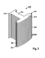
- Fig. 3 shows the core segment 210 of Fig. 2 , illustratively comprising a plurality of stacked laminations, wherein for the sake of simplicity of illustration, only four of the laminations are designated by reference numeral 399.
- soft iron or another soft magnetic material may be provided for a core segment.
- a first lateral joining surface 302 with a connecting groove 312 formed in the axial direction is provided on the yoke section 212, and a connecting web 314 is formed in the axial direction on a second lateral joining surface 304.
- the connecting groove 312 and the connecting web 314 serve to connect to a connecting web or a connecting groove, which are respectively provided on adjacent core segments.
- the in Fig. 3 described construction of the core segment 210 as representative of the core segments 220, 230, 240, 250, 260, 270, 280, 290, thus at their yoke sections 222, 232, 242, 252, 262, 272, 282, and 292, respectively also respectively a connecting groove and a connecting web, which are connected to associated connecting webs or connecting grooves of adjacent core segments.
- the connecting groove 312 of the core segment 210 is connectable to an associated connecting web of the core segment 220 and the connecting web 314 is connectable to an associated connecting groove of the core segment 290, etc.
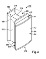
- Fig. 4 shows the core segment 210 of Fig. 3 , which is illustratively provided with a plastic sheath 410.
- the plastic sheath 410 is formed by plastic spraying on the core segment 210 and encloses at least the yoke section 212 and the tooth root section 216 at least in sections.
- the plastic sheath 410 may also be formed from one or more plastic parts which can be attached to the core segment 210.
- the plastic sheath 410 for fixing the core segment 210 forming, stacked laminations can be used together, so that a separate fixation by z. B. welding can be dispensed with.
- the plastic sheath 410 preferably surrounds the core segment 210 completely or at least in such a way that only side faces 482, 484 which are remote from one another and are formed on the tooth root section 216 or the yoke section 212 are not enclosed by the plastic sheath 410.
- the plastic sheathing 410 illustratively forms a winding groove 450, which encloses at least the tooth section 214 and is designed to receive a single winding 499 indicated by a broken line, which z. B. by flyer wrapping or coil winding on the plastic sheath 410 is wound, wherein the plastic sheath 410, the single winding 499 preferably electrically insulated from the core segment 210.
- the core segment 210 provided with the plastic sheath 410 and the single winding 499 is also referred to as "stator segment”.
- Fig. 5 shows the electric motor 100 of Fig. 1 illustratively comprising a housing 600, exemplifying the stator 150 of FIG Fig. 1 is arranged, the z. B. arranged around a stator central axis 603 stator segments 210, 220, 230, 240, 250, 260, 270, 280, 290 of Fig. 2 can have.
- the stator 150 has at least one and illustratively two connecting elements 601, 602 for connecting these stator segments 210, 220, 230, 240, 250, 260, 270, 280, 290 of FIG Fig. 2 on, wherein the connecting element 601 is exemplified in the manner of a bearing cap and the connecting element 602 is formed by way of example in the manner of a Verschalteplatte, as in the following Fig. 6 described.
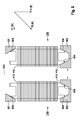
- Fig. 6 shows by way of example each with an associated plastic sheath 410 of Fig. 4 provided stator segments 210 and 250 of Fig. 2 , which are illustratively arranged mirror-symmetrically to a mirror plane containing the Statorstoffachse 603.
- the stator segments 210 and 250 are according to the arrangement 200 of FIG Fig. 2 arranged opposite each other, as parts of according to Fig. 1 Stator 150 associated with the electric motor 100, with the stator segments 210, 220, 230, 240, 250, 260, 270, 280, 290, arranged annularly about the stator central axis 603 Fig. 2 , as in Fig. 5 described.
- the plastic sheaths 410 of the stator segments 210, 250 are disposed at a first axial end over the annular bearing cap 601 and at the opposite, second axial end via the annular shroud plate 602 of FIG Fig. 5 connected to each other, wherein the stator segments 210, 250 are acted upon by a force acting radially inwardly in the direction of the stator central axis 603.
- the bearing cap 601 is in this case pressed onto the first axial end of the stator segments 210, 250 and the second axial end of the stator segments 210, 250 is pressed into the circuit board 602.
- a radially inwardly acting clamping of the stator segments 210, 250 is effected.
- a force diagram is shown, the generation of a force acting radially to Statorffenachse 603 FR as a result of a Statorffenachse 603 perpendicularly pointing force F1 and a force F2 perpendicular thereto, by connecting the bearing cap 601 and the Verschalteplatte 602 with the plastic sheaths 410 of Stator segments 210, 250, in particular by mechanical force by means of imprinting in the direction of the force F2, illustrated.
- the bearing cap 601 and / or the switching plate 602 comprise a deformable material made of spring steel, an elastomer (eg rubber), in particular a thermoplastic plastic and / or a biopolymer (eg wood).
- the bearing cap 601 and / or the Verschalteplatte 602 by welding, ultrasonic welding, laser transmission welding, shrinking, gluing, shrink-bonding, clipping and / or pressing with the plastic sheaths 410 of the stator segments 210, 250 is connected.
- connection areas 604 are produced which can be generated by such connection methods.
- a welding which is not to be understood as limiting the invention.
- FIGS. 7a to 7d show various embodiments of exemplary geometric configurations of sections shown axial ends of plastic sheaths and partially shown connecting elements, for the realization of the plastic sheath 410 and the bearing cap 601 and / or the Verschalteplatte 602 of Fig. 6 Application can be found.
- connecting elements for realizing the bearing cap 601 of FIG Fig. 6
- Such geometric formations may be provided in the manner of bevels, projections, recesses and / or depressions to increase a mutual bonding surface and / or improve positioning accuracy in attachment of the fastener to the axial end of the plastic jacket.
- Fig. 7a shows an exemplary axial end 610a of the plastic sheath 410 of FIG Fig. 6 with a rectangular cross-section, and a beveled connecting element 601 a for the realization of the bearing cap 601 of Fig. 6 ,
- this connecting element 601a to the axial end 610a, the edge of the axial end 610a facing the connecting element 601a is melted off until the connecting element 601a and the axial end 610a have at least approximately corresponding joining surfaces, ie approximately parallel to one another, over which these melted plastic are welded together.
- Fig. 7b shows an exemplary axial end 610b of the plastic sheath 410 of FIG Fig. 6 , which illustratively has a chamfer, and an exemplary connecting element 601b for realizing the bearing cap 601 of FIG Fig. 6 , which by way of example has a partial bevel with a web-like end edge, which illustratively runs approximately parallel to the axial end 610b.
- the edge of the axial end 610b facing the connecting element 601b is melted off until the connecting element 601b and the axial end 610b have at least approximately corresponding joining surfaces, ie approximately parallel to one another, over which these melted plastic are welded together.
- melted plastic passes between the web-like end edge of the connecting element 601b and the axial end 610b, so that the entire joining surface can be increased.
- Fig. 7c shows an exemplary axial end 610c of the plastic sheath 410 of FIG Fig. 6 , on which illustratively a depression 611 and a web-like extension are formed, as well as an exemplary bevelled connecting element 601c for the realization of the bearing cap 601 of FIG Fig. 6 ,
- the edge of the axial end 610c facing the connecting element 601c is melted off until the connecting element 601c and the axial end 610c have at least approximately corresponding joining surfaces, ie approximately parallel to one another, over which these melted plastic are welded together.
- molten plastic passes into the depression 611 and from there between the web-like widening of the axial end 610c and the connecting element 601c, so that the entire joining surface can still be increased.
- Fig. 7d shows a section 601d of the bearing cap 601 of Fig. 6 and an exemplary axial end 610d of the plastic sheath 410 of FIG. 3 shown in a front view and a rear view Fig. 6 which illustratively has a recess 611 '.
- the connecting element 610d has an exemplary elevation 604, which, for. B. can be used to implement a suitable energy directors application.
- the elevation 604 to the recess 611 'on the one hand the alignment of the connecting element 601d is facilitated relative to the axial end 610d.
- the melting in the region of the projection 604 acting as the energy directors is accelerated.
- Fig. 8a and Fig. 8b show an exemplary assembly of a z. B. for the realization of the bearing cap 601 of Fig. 6 usable connector 801 a according to another exemplary embodiment of an exemplary axial end 810a of the plastic sheath 410 of Fig. 6 according to another exemplary embodiment.
- the connecting element 801a and the axial end 810a have, for example, mutually facing and at least approximately mutually parallel bevels.
- the axial end 810a is in Fig. 8b illustratively provided with an energy director 611a.
- This energy directors 611 a is preferably circumferentially on the plastic sheaths 410 of all the stator segments 210, 220, 230, 240, 250, 260, 270, 280, 290 of Fig. 2 educated.
- the connecting element 801 a is pressed onto the axial end 810 a with a force acting in the direction of the arrow 700.
- the connecting member 801a and the axial end 810a are welded together as in the above Fig. 7a to 7d described by way of example.
- the description of the use of the energy director 811a is merely exemplary in nature and should not be considered as limiting the invention, which is also practicable without the use of the energy director 811a.
- a suitable, melting additive material for melt production can be used.
- the use of the energy directors 811 a is advantageous in order to achieve improved and above all controlled melt production during welding.
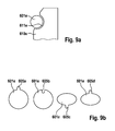
- Fig. 9a illustrates another embodiment with an example ring-shaped connecting element 601e.
- This is configured, for example, in a at an exemplary axial end 610 e of the plastic sheath 410 of Fig. 6 provided recess 611e, z. B. after pressing the connecting element 601e on the annularly arranged stator segments 210, 220, 230, 240, 250, 260, 270, 280, 290 of Fig. 2 to intervene.
- the annular connecting element 601e z. B. be designed in the manner of an elastic ring, for example as an available under pressure spring ring made of metal or an elastomer such as rubber or another biopolymer or a plastic, for. B.
- the connecting element 601e may also be designed in the manner of a rigid ring made of a rigid biopolymer such as wood or ceramic, glass or a fiber composite material for gluing or clipping into the recess 611e.
- Fig. 9b shows examples of geometrically different configurations of the formed as an elastic ring connecting element 601e of Fig. 9a with enlargements or bulges 605a, 605b, 605c and 605d which enlarge the circumference under the action of a contact pressure, with which an increase of the contact pressure z. B. after connection to the stator segments 210, 220, 230, 240, 250, 260, 270, 280, 290 of Fig. 2 is effected.
- the bulge 605a is illustratively radially inwardly formed and the bulge 605b is formed radially outward of the elastic ring 601e.
- the protrusions 605c and 605d extend from the elastic ring 601e in opposite axial directions from the axis of rotation thereof.
Landscapes
- Engineering & Computer Science (AREA)
- Power Engineering (AREA)
- Manufacturing & Machinery (AREA)
- Iron Core Of Rotating Electric Machines (AREA)
- Insulation, Fastening Of Motor, Generator Windings (AREA)
Applications Claiming Priority (1)
| Application Number | Priority Date | Filing Date | Title |
|---|---|---|---|
| DE102011086768A DE102011086768A1 (de) | 2011-11-22 | 2011-11-22 | Elektromotor mit einem segmentierten Stator |
Publications (3)
| Publication Number | Publication Date |
|---|---|
| EP2597751A2 true EP2597751A2 (fr) | 2013-05-29 |
| EP2597751A3 EP2597751A3 (fr) | 2016-12-28 |
| EP2597751B1 EP2597751B1 (fr) | 2019-01-09 |
Family
ID=47520671
Family Applications (1)
| Application Number | Title | Priority Date | Filing Date |
|---|---|---|---|
| EP12192966.5A Not-in-force EP2597751B1 (fr) | 2011-11-22 | 2012-11-16 | Moteur électrique avec un stator segmenté |
Country Status (3)
| Country | Link |
|---|---|
| EP (1) | EP2597751B1 (fr) |
| CN (1) | CN103138422A (fr) |
| DE (1) | DE102011086768A1 (fr) |
Cited By (1)
| Publication number | Priority date | Publication date | Assignee | Title |
|---|---|---|---|---|
| EP3232542A1 (fr) * | 2016-04-15 | 2017-10-18 | Bühler Motor GmbH | Moteur à courant continu à commutation électronique comprenant des pôles uniques |
Families Citing this family (2)
| Publication number | Priority date | Publication date | Assignee | Title |
|---|---|---|---|---|
| DE102022207900A1 (de) * | 2022-08-01 | 2024-02-01 | Zf Friedrichshafen Ag | Stator für einen Elektromotor sowie Elektromotor, umfassend einen solchen Stator |
| EP4465486A1 (fr) * | 2023-05-19 | 2024-11-20 | Hamilton Sundstrand Corporation | Ensemble stator |
Citations (1)
| Publication number | Priority date | Publication date | Assignee | Title |
|---|---|---|---|---|
| DE19857954A1 (de) | 1998-12-16 | 2000-06-21 | Pierburg Ag | Elektronisch kommutierter Gleichstrommotor |
Family Cites Families (12)
| Publication number | Priority date | Publication date | Assignee | Title |
|---|---|---|---|---|
| US4990809A (en) * | 1987-04-27 | 1991-02-05 | The Superior Electric Company | Variable reluctance motor |
| JP3730218B2 (ja) * | 2000-08-29 | 2005-12-21 | 三菱電機株式会社 | 積重ステータコアとその製造方法および回転電動機とその製造方法 |
| US6844653B2 (en) * | 2003-03-31 | 2005-01-18 | Valeo Electrical Systems, Inc. | Stator design for permanent magnet motor with combination slot wedge and tooth locator |
| DE50303111D1 (de) * | 2003-07-12 | 2006-06-01 | Grundfos As | Segmentierter Stator |
| JP4725721B2 (ja) * | 2005-01-24 | 2011-07-13 | 株式会社富士通ゼネラル | アキシャルエアギャップ型電動機 |
| US7800276B2 (en) * | 2007-05-17 | 2010-09-21 | Kurz-Kasch, Inc. | Rotor assembly |
| DE102008023923B4 (de) * | 2007-07-10 | 2025-06-18 | Sew-Eurodrive Gmbh & Co Kg | Stator, Verfahren zur Herstellung von Statorsegmenten, Verfahren zur Herstellung von einem Stator |
| DE102008033601A1 (de) * | 2008-07-17 | 2010-01-21 | Sew-Eurodrive Gmbh & Co. Kg | Elektromotor |
| JP5363255B2 (ja) * | 2009-09-18 | 2013-12-11 | 株式会社ミツバ | ステータの製造方法、およびステータ |
| CN102122868B (zh) * | 2010-01-08 | 2016-06-29 | 思博莫顿股份公司 | 电机定子及其制造方法 |
| CN101951038A (zh) * | 2010-09-13 | 2011-01-19 | 浙江西子富沃德电机有限公司 | 电机的定子铁芯及其制作方法 |
| CN102185391B (zh) * | 2011-05-13 | 2013-01-30 | 鹤山市明可达实业有限公司 | 一种电机定子及其生产方法 |
-
2011
- 2011-11-22 DE DE102011086768A patent/DE102011086768A1/de not_active Withdrawn
-
2012
- 2012-11-16 EP EP12192966.5A patent/EP2597751B1/fr not_active Not-in-force
- 2012-11-21 CN CN2012105963213A patent/CN103138422A/zh active Pending
Patent Citations (1)
| Publication number | Priority date | Publication date | Assignee | Title |
|---|---|---|---|---|
| DE19857954A1 (de) | 1998-12-16 | 2000-06-21 | Pierburg Ag | Elektronisch kommutierter Gleichstrommotor |
Cited By (1)
| Publication number | Priority date | Publication date | Assignee | Title |
|---|---|---|---|---|
| EP3232542A1 (fr) * | 2016-04-15 | 2017-10-18 | Bühler Motor GmbH | Moteur à courant continu à commutation électronique comprenant des pôles uniques |
Also Published As
| Publication number | Publication date |
|---|---|
| DE102011086768A1 (de) | 2013-05-23 |
| EP2597751B1 (fr) | 2019-01-09 |
| CN103138422A (zh) | 2013-06-05 |
| EP2597751A3 (fr) | 2016-12-28 |
Similar Documents
| Publication | Publication Date | Title |
|---|---|---|
| DE102016120208B4 (de) | Fügeverfahren für spulenenden von segmentspulen für einen stator und fügevorrichtung | |
| DE68919100T2 (de) | Piezoelektrischer Summer und Verfahren zu dessen Herstellung. | |
| EP2596566B1 (fr) | Moteur électrique comportant un stator segmenté | |
| EP4060868B1 (fr) | Paquet de stator modulaire, segmenté | |
| WO2018036952A1 (fr) | Rotor d'une machine électrique et procédé de montage du rotor | |
| EP2548291B1 (fr) | Moteur à rotor extérieur | |
| DE102009023080B4 (de) | Elektrische Maschine | |
| WO2016110423A1 (fr) | Plaque de câblage pour un stator d'une machine électrique et procédé de fabrication de ladite plaque de câblage | |
| DE102013220562B4 (de) | Baugruppe für eine elektrische Maschine, Verfahren zur Herstellung einer Baugruppe und elektrische Maschine mit einer Baugruppe | |
| DE112016005607T5 (de) | Anker für eine elektrische Rotationsmaschine | |
| DE102009003228B4 (de) | Elektrische Maschine | |
| DE60303636T2 (de) | Statorstruktur eines Resolvers | |
| EP2597751B1 (fr) | Moteur électrique avec un stator segmenté | |
| WO2018138187A1 (fr) | Anneau de noyau feuilleté comprenant une pluralité de segments d'anneau de noyau feuilleté, et rotor | |
| EP0175798A1 (fr) | Dispositif et méthode pour régler le jeu axial entre rotor et paliers fixés au stator d'un moteur électrique | |
| DE102016218822A1 (de) | Stator für eine elektrische Maschine, elektrische Maschine für ein Kraftfahrzeug und Kraftfahrzeug | |
| EP4066359B1 (fr) | Stator dans une machine électrique comportant un dispositif de câblage, et machine électrique | |
| EP1851845B1 (fr) | Moteur electrique comprenant une partie segmentee constituee de plusieurs paquets de toles et procede d'assemblage de ces paquets de toles | |
| DE102013004851A1 (de) | Rotor für einen Elektromotor, der eine Drehwelle und ein Joch umfasst, das sicher auf die Drehwelle gepasst ist | |
| DE102005024653A1 (de) | Stator einer sich drehenden elektrischen Maschine und Herstellungsverfahren des Stators | |
| WO2021018706A1 (fr) | Stator et dispositif d'ossature pour un tel stator | |
| DE10038234A1 (de) | Verfahren und Satz zur Herstellung eines Ständers einer Elektrischen Maschine sowie Ständer für eine Elektrische Maschine | |
| EP2676354B1 (fr) | Stator de moteur à griffes | |
| EP2009769A2 (fr) | Support d'enroulement pour un moteur électrique avec enroulements individuels | |
| DE102013219993A1 (de) | Elektromotor mit einem segmentierten Stator |
Legal Events
| Date | Code | Title | Description |
|---|---|---|---|
| PUAI | Public reference made under article 153(3) epc to a published international application that has entered the european phase |
Free format text: ORIGINAL CODE: 0009012 |
|
| AK | Designated contracting states |
Kind code of ref document: A2 Designated state(s): AL AT BE BG CH CY CZ DE DK EE ES FI FR GB GR HR HU IE IS IT LI LT LU LV MC MK MT NL NO PL PT RO RS SE SI SK SM TR |
|
| AX | Request for extension of the european patent |
Extension state: BA ME |
|
| PUAL | Search report despatched |
Free format text: ORIGINAL CODE: 0009013 |
|
| AK | Designated contracting states |
Kind code of ref document: A3 Designated state(s): AL AT BE BG CH CY CZ DE DK EE ES FI FR GB GR HR HU IE IS IT LI LT LU LV MC MK MT NL NO PL PT RO RS SE SI SK SM TR |
|
| AX | Request for extension of the european patent |
Extension state: BA ME |
|
| RIC1 | Information provided on ipc code assigned before grant |
Ipc: H02K 1/14 20060101AFI20161121BHEP Ipc: H02K 5/02 20060101ALI20161121BHEP Ipc: H02K 3/52 20060101ALN20161121BHEP Ipc: H02K 15/02 20060101ALN20161121BHEP Ipc: H02K 1/18 20060101ALI20161121BHEP |
|
| STAA | Information on the status of an ep patent application or granted ep patent |
Free format text: STATUS: REQUEST FOR EXAMINATION WAS MADE |
|
| 17P | Request for examination filed |
Effective date: 20170628 |
|
| RBV | Designated contracting states (corrected) |
Designated state(s): AL AT BE BG CH CY CZ DE DK EE ES FI FR GB GR HR HU IE IS IT LI LT LU LV MC MK MT NL NO PL PT RO RS SE SI SK SM TR |
|
| GRAP | Despatch of communication of intention to grant a patent |
Free format text: ORIGINAL CODE: EPIDOSNIGR1 |
|
| STAA | Information on the status of an ep patent application or granted ep patent |
Free format text: STATUS: GRANT OF PATENT IS INTENDED |
|
| RIC1 | Information provided on ipc code assigned before grant |
Ipc: H02K 15/02 20060101ALN20180627BHEP Ipc: H02K 1/18 20060101ALI20180627BHEP Ipc: H02K 3/52 20060101ALN20180627BHEP Ipc: H02K 5/02 20060101ALI20180627BHEP Ipc: H02K 1/14 20060101AFI20180627BHEP |
|
| INTG | Intention to grant announced |
Effective date: 20180718 |
|
| RIC1 | Information provided on ipc code assigned before grant |
Ipc: H02K 1/18 20060101ALI20180706BHEP Ipc: H02K 5/02 20060101ALI20180706BHEP Ipc: H02K 1/14 20060101AFI20180706BHEP Ipc: H02K 15/02 20060101ALN20180706BHEP Ipc: H02K 3/52 20060101ALN20180706BHEP |
|
| GRAS | Grant fee paid |
Free format text: ORIGINAL CODE: EPIDOSNIGR3 |
|
| GRAA | (expected) grant |
Free format text: ORIGINAL CODE: 0009210 |
|
| STAA | Information on the status of an ep patent application or granted ep patent |
Free format text: STATUS: THE PATENT HAS BEEN GRANTED |
|
| AK | Designated contracting states |
Kind code of ref document: B1 Designated state(s): AL AT BE BG CH CY CZ DE DK EE ES FI FR GB GR HR HU IE IS IT LI LT LU LV MC MK MT NL NO PL PT RO RS SE SI SK SM TR |
|
| REG | Reference to a national code |
Ref country code: GB Ref legal event code: FG4D Free format text: NOT ENGLISH |
|
| REG | Reference to a national code |
Ref country code: CH Ref legal event code: EP Ref country code: AT Ref legal event code: REF Ref document number: 1088551 Country of ref document: AT Kind code of ref document: T Effective date: 20190115 |
|
| REG | Reference to a national code |
Ref country code: DE Ref legal event code: R096 Ref document number: 502012014131 Country of ref document: DE |
|
| REG | Reference to a national code |
Ref country code: IE Ref legal event code: FG4D Free format text: LANGUAGE OF EP DOCUMENT: GERMAN |
|
| REG | Reference to a national code |
Ref country code: NL Ref legal event code: MP Effective date: 20190109 |
|
| REG | Reference to a national code |
Ref country code: LT Ref legal event code: MG4D |
|
| PG25 | Lapsed in a contracting state [announced via postgrant information from national office to epo] |
Ref country code: NL Free format text: LAPSE BECAUSE OF FAILURE TO SUBMIT A TRANSLATION OF THE DESCRIPTION OR TO PAY THE FEE WITHIN THE PRESCRIBED TIME-LIMIT Effective date: 20190109 |
|
| PG25 | Lapsed in a contracting state [announced via postgrant information from national office to epo] |
Ref country code: PL Free format text: LAPSE BECAUSE OF FAILURE TO SUBMIT A TRANSLATION OF THE DESCRIPTION OR TO PAY THE FEE WITHIN THE PRESCRIBED TIME-LIMIT Effective date: 20190109 Ref country code: FI Free format text: LAPSE BECAUSE OF FAILURE TO SUBMIT A TRANSLATION OF THE DESCRIPTION OR TO PAY THE FEE WITHIN THE PRESCRIBED TIME-LIMIT Effective date: 20190109 Ref country code: LT Free format text: LAPSE BECAUSE OF FAILURE TO SUBMIT A TRANSLATION OF THE DESCRIPTION OR TO PAY THE FEE WITHIN THE PRESCRIBED TIME-LIMIT Effective date: 20190109 Ref country code: ES Free format text: LAPSE BECAUSE OF FAILURE TO SUBMIT A TRANSLATION OF THE DESCRIPTION OR TO PAY THE FEE WITHIN THE PRESCRIBED TIME-LIMIT Effective date: 20190109 Ref country code: SE Free format text: LAPSE BECAUSE OF FAILURE TO SUBMIT A TRANSLATION OF THE DESCRIPTION OR TO PAY THE FEE WITHIN THE PRESCRIBED TIME-LIMIT Effective date: 20190109 Ref country code: NO Free format text: LAPSE BECAUSE OF FAILURE TO SUBMIT A TRANSLATION OF THE DESCRIPTION OR TO PAY THE FEE WITHIN THE PRESCRIBED TIME-LIMIT Effective date: 20190409 Ref country code: PT Free format text: LAPSE BECAUSE OF FAILURE TO SUBMIT A TRANSLATION OF THE DESCRIPTION OR TO PAY THE FEE WITHIN THE PRESCRIBED TIME-LIMIT Effective date: 20190509 |
|
| PG25 | Lapsed in a contracting state [announced via postgrant information from national office to epo] |
Ref country code: GR Free format text: LAPSE BECAUSE OF FAILURE TO SUBMIT A TRANSLATION OF THE DESCRIPTION OR TO PAY THE FEE WITHIN THE PRESCRIBED TIME-LIMIT Effective date: 20190410 Ref country code: IS Free format text: LAPSE BECAUSE OF FAILURE TO SUBMIT A TRANSLATION OF THE DESCRIPTION OR TO PAY THE FEE WITHIN THE PRESCRIBED TIME-LIMIT Effective date: 20190509 Ref country code: HR Free format text: LAPSE BECAUSE OF FAILURE TO SUBMIT A TRANSLATION OF THE DESCRIPTION OR TO PAY THE FEE WITHIN THE PRESCRIBED TIME-LIMIT Effective date: 20190109 Ref country code: LV Free format text: LAPSE BECAUSE OF FAILURE TO SUBMIT A TRANSLATION OF THE DESCRIPTION OR TO PAY THE FEE WITHIN THE PRESCRIBED TIME-LIMIT Effective date: 20190109 Ref country code: BG Free format text: LAPSE BECAUSE OF FAILURE TO SUBMIT A TRANSLATION OF THE DESCRIPTION OR TO PAY THE FEE WITHIN THE PRESCRIBED TIME-LIMIT Effective date: 20190409 Ref country code: RS Free format text: LAPSE BECAUSE OF FAILURE TO SUBMIT A TRANSLATION OF THE DESCRIPTION OR TO PAY THE FEE WITHIN THE PRESCRIBED TIME-LIMIT Effective date: 20190109 |
|
| REG | Reference to a national code |
Ref country code: DE Ref legal event code: R097 Ref document number: 502012014131 Country of ref document: DE |
|
| PG25 | Lapsed in a contracting state [announced via postgrant information from national office to epo] |
Ref country code: AL Free format text: LAPSE BECAUSE OF FAILURE TO SUBMIT A TRANSLATION OF THE DESCRIPTION OR TO PAY THE FEE WITHIN THE PRESCRIBED TIME-LIMIT Effective date: 20190109 Ref country code: CZ Free format text: LAPSE BECAUSE OF FAILURE TO SUBMIT A TRANSLATION OF THE DESCRIPTION OR TO PAY THE FEE WITHIN THE PRESCRIBED TIME-LIMIT Effective date: 20190109 Ref country code: SK Free format text: LAPSE BECAUSE OF FAILURE TO SUBMIT A TRANSLATION OF THE DESCRIPTION OR TO PAY THE FEE WITHIN THE PRESCRIBED TIME-LIMIT Effective date: 20190109 Ref country code: RO Free format text: LAPSE BECAUSE OF FAILURE TO SUBMIT A TRANSLATION OF THE DESCRIPTION OR TO PAY THE FEE WITHIN THE PRESCRIBED TIME-LIMIT Effective date: 20190109 Ref country code: IT Free format text: LAPSE BECAUSE OF FAILURE TO SUBMIT A TRANSLATION OF THE DESCRIPTION OR TO PAY THE FEE WITHIN THE PRESCRIBED TIME-LIMIT Effective date: 20190109 Ref country code: EE Free format text: LAPSE BECAUSE OF FAILURE TO SUBMIT A TRANSLATION OF THE DESCRIPTION OR TO PAY THE FEE WITHIN THE PRESCRIBED TIME-LIMIT Effective date: 20190109 Ref country code: DK Free format text: LAPSE BECAUSE OF FAILURE TO SUBMIT A TRANSLATION OF THE DESCRIPTION OR TO PAY THE FEE WITHIN THE PRESCRIBED TIME-LIMIT Effective date: 20190109 |
|
| PLBE | No opposition filed within time limit |
Free format text: ORIGINAL CODE: 0009261 |
|
| STAA | Information on the status of an ep patent application or granted ep patent |
Free format text: STATUS: NO OPPOSITION FILED WITHIN TIME LIMIT |
|
| PG25 | Lapsed in a contracting state [announced via postgrant information from national office to epo] |
Ref country code: SM Free format text: LAPSE BECAUSE OF FAILURE TO SUBMIT A TRANSLATION OF THE DESCRIPTION OR TO PAY THE FEE WITHIN THE PRESCRIBED TIME-LIMIT Effective date: 20190109 |
|
| 26N | No opposition filed |
Effective date: 20191010 |
|
| PG25 | Lapsed in a contracting state [announced via postgrant information from national office to epo] |
Ref country code: SI Free format text: LAPSE BECAUSE OF FAILURE TO SUBMIT A TRANSLATION OF THE DESCRIPTION OR TO PAY THE FEE WITHIN THE PRESCRIBED TIME-LIMIT Effective date: 20190109 |
|
| PG25 | Lapsed in a contracting state [announced via postgrant information from national office to epo] |
Ref country code: TR Free format text: LAPSE BECAUSE OF FAILURE TO SUBMIT A TRANSLATION OF THE DESCRIPTION OR TO PAY THE FEE WITHIN THE PRESCRIBED TIME-LIMIT Effective date: 20190109 |
|
| PGFP | Annual fee paid to national office [announced via postgrant information from national office to epo] |
Ref country code: DE Payment date: 20200124 Year of fee payment: 8 |
|
| REG | Reference to a national code |
Ref country code: CH Ref legal event code: PL |
|
| PG25 | Lapsed in a contracting state [announced via postgrant information from national office to epo] |
Ref country code: MC Free format text: LAPSE BECAUSE OF FAILURE TO SUBMIT A TRANSLATION OF THE DESCRIPTION OR TO PAY THE FEE WITHIN THE PRESCRIBED TIME-LIMIT Effective date: 20190109 Ref country code: LU Free format text: LAPSE BECAUSE OF NON-PAYMENT OF DUE FEES Effective date: 20191116 Ref country code: CH Free format text: LAPSE BECAUSE OF NON-PAYMENT OF DUE FEES Effective date: 20191130 Ref country code: LI Free format text: LAPSE BECAUSE OF NON-PAYMENT OF DUE FEES Effective date: 20191130 |
|
| REG | Reference to a national code |
Ref country code: BE Ref legal event code: MM Effective date: 20191130 |
|
| GBPC | Gb: european patent ceased through non-payment of renewal fee |
Effective date: 20191116 |
|
| PG25 | Lapsed in a contracting state [announced via postgrant information from national office to epo] |
Ref country code: GB Free format text: LAPSE BECAUSE OF NON-PAYMENT OF DUE FEES Effective date: 20191116 Ref country code: IE Free format text: LAPSE BECAUSE OF NON-PAYMENT OF DUE FEES Effective date: 20191116 Ref country code: FR Free format text: LAPSE BECAUSE OF NON-PAYMENT OF DUE FEES Effective date: 20191130 |
|
| PG25 | Lapsed in a contracting state [announced via postgrant information from national office to epo] |
Ref country code: BE Free format text: LAPSE BECAUSE OF NON-PAYMENT OF DUE FEES Effective date: 20191130 |
|
| REG | Reference to a national code |
Ref country code: AT Ref legal event code: MM01 Ref document number: 1088551 Country of ref document: AT Kind code of ref document: T Effective date: 20191116 |
|
| PG25 | Lapsed in a contracting state [announced via postgrant information from national office to epo] |
Ref country code: AT Free format text: LAPSE BECAUSE OF NON-PAYMENT OF DUE FEES Effective date: 20191116 |
|
| PG25 | Lapsed in a contracting state [announced via postgrant information from national office to epo] |
Ref country code: CY Free format text: LAPSE BECAUSE OF FAILURE TO SUBMIT A TRANSLATION OF THE DESCRIPTION OR TO PAY THE FEE WITHIN THE PRESCRIBED TIME-LIMIT Effective date: 20190109 |
|
| REG | Reference to a national code |
Ref country code: DE Ref legal event code: R119 Ref document number: 502012014131 Country of ref document: DE |
|
| PG25 | Lapsed in a contracting state [announced via postgrant information from national office to epo] |
Ref country code: HU Free format text: LAPSE BECAUSE OF FAILURE TO SUBMIT A TRANSLATION OF THE DESCRIPTION OR TO PAY THE FEE WITHIN THE PRESCRIBED TIME-LIMIT; INVALID AB INITIO Effective date: 20121116 Ref country code: MT Free format text: LAPSE BECAUSE OF FAILURE TO SUBMIT A TRANSLATION OF THE DESCRIPTION OR TO PAY THE FEE WITHIN THE PRESCRIBED TIME-LIMIT Effective date: 20190109 |
|
| PG25 | Lapsed in a contracting state [announced via postgrant information from national office to epo] |
Ref country code: DE Free format text: LAPSE BECAUSE OF NON-PAYMENT OF DUE FEES Effective date: 20210601 |
|
| PG25 | Lapsed in a contracting state [announced via postgrant information from national office to epo] |
Ref country code: MK Free format text: LAPSE BECAUSE OF FAILURE TO SUBMIT A TRANSLATION OF THE DESCRIPTION OR TO PAY THE FEE WITHIN THE PRESCRIBED TIME-LIMIT Effective date: 20190109 |