EP2599384A1 - Brunsterkennungsvorrichtung und brunsterkennungssystem - Google Patents
Brunsterkennungsvorrichtung und brunsterkennungssystem Download PDFInfo
- Publication number
- EP2599384A1 EP2599384A1 EP11812021.1A EP11812021A EP2599384A1 EP 2599384 A1 EP2599384 A1 EP 2599384A1 EP 11812021 A EP11812021 A EP 11812021A EP 2599384 A1 EP2599384 A1 EP 2599384A1
- Authority
- EP
- European Patent Office
- Prior art keywords
- estrus
- activity
- case
- amount
- livestock animal
- Prior art date
- Legal status (The legal status is an assumption and is not a legal conclusion. Google has not performed a legal analysis and makes no representation as to the accuracy of the status listed.)
- Withdrawn
Links
Images




Classifications
-
- A—HUMAN NECESSITIES
- A01—AGRICULTURE; FORESTRY; ANIMAL HUSBANDRY; HUNTING; TRAPPING; FISHING
- A01K—ANIMAL HUSBANDRY; AVICULTURE; APICULTURE; PISCICULTURE; FISHING; REARING OR BREEDING ANIMALS, NOT OTHERWISE PROVIDED FOR; NEW BREEDS OF ANIMALS
- A01K29/00—Other apparatus for animal husbandry
- A01K29/005—Monitoring or measuring activity
-
- A—HUMAN NECESSITIES
- A61—MEDICAL OR VETERINARY SCIENCE; HYGIENE
- A61D—VETERINARY INSTRUMENTS, IMPLEMENTS, TOOLS, OR METHODS
- A61D17/00—Devices for indicating trouble during labour of animals ; Methods or instruments for detecting pregnancy-related states of animals
- A61D17/002—Devices for indicating trouble during labour of animals ; Methods or instruments for detecting pregnancy-related states of animals for detecting period of heat of animals, i.e. for detecting oestrus
Definitions
- the present invention relates to a device for detecting estrus in livestock, especially cows.
- estrus In cows, and particularly, to find out when cows come into estrus.
- Some devices for detecting estrus include a pedometer (see Patent Literature 1).
- Such a pedometer is attached to a target cow.
- the detection device divides each day into a plurality of time periods, and extracts the number of her steps counted by the pedometer for each time period.
- the detection device then compares the counted steps with the number of her steps corresponding to the same time period in the past "n" days, thereby determining whether the cow is in estrus or not from the comparison result.
- the device includes counting device 101 and a least one pedometer 102.
- Counting device 101 includes computer 103 and communication device 104.
- Pedometer 102 is secured to a cow's body, for example, around a cow's neck or leg with a belt or something.
- Pedometer 102 includes a step counting unit, a communication unit, and a control unit.
- the step counting unit counts the number of her steps, and transmits it to the control unit.
- the control unit accumulates the number of her steps up to a predetermined time, and transmits the accumulated value to the communication unit together with a signal for identifying individual cows.
- the communication unit receives the accumulated value and the signal, and transmits them to communication device 104. After the communication unit transmits the value and the signal to communication device 104, the control unit resets the accumulated value.
- Computer 103 stores the data of the number of her past steps in the form of, for example, D 1 , D 2 , D 3 , D 4 (2003).
- Computer 103 compares the number of her most recent steps received from communication device 104 with the data of the number of her past steps. When the comparison indicates that the number of her most recent steps is larger than the data of her past steps, computer 103 determines that the cow is in estrus.
- the present invention is directed to provide a simple device for detecting estrus in livestock.
- the estrus detection device of the present invention includes a case to be attached to a livestock animal; an activity sensor contained in the case, the activity sensor detecting a motion of the livestock animal; a signal processing unit contained in the case, the signal processing unit converting the output of the activity sensor to the amount of activity; a temporary storage unit contained in the case, the temporary storage unit storing the output of the signal processing unit as the present amount of activity; a storage unit contained in the case, the storage unit storing, as a past amount of activity for a predetermined past time period, the amount of activity stored so far in the temporary storage unit; an estrus determination unit contained in the case, the estrus determination unit determining whether the livestock animal is in estrus or not based on the past amount of activity and the present amount of activity; and a display part contained in the case, the display part showing that the livestock animal is in estrus when the estrus determination unit has determined that the livestock animal is in estrus.
- the estrus detection device is attached to livestock such as cows that are close to estrus. Whether they are in estrus or not can be detected only by this estrus detection device, without a large-scale system.
- the estrus detection device can be initialized using the characteristics of a triaxial acceleration sensor. Furthermore, the estrus detection device can be operated without opening the case, thereby being hermetically sealed.
- Figs. 1A and 1B are external views of an estrus detection device according to the first exemplary embodiment.
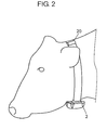
- Estrus detection device 1 has case 2 and belt 20 under it. As shown in Fig. 2 , case 2 with belt 20 is attached around the neck of a cow as livestock. Estrus detection device 1 can be attached to other livestock such as pigs and cows.
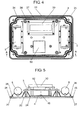
- case 2 The inner structure of case 2 will now be described with reference to Figs. 3 to 6 .
- Case 2 contains display board 3, control board 4, and power supply 5.
- Display board 3 includes display part 30.
- Control board 4 includes triaxial acceleration sensor 40 as an activity sensor, signal processing unit 41, temporary storage unit 42, storage unit 43, and estrus determination unit 44.
- the activity sensor which detects the motion of a livestock animal, can be one of various kinds of acceleration sensors. Among them, triaxial acceleration sensor 40 can detect the magnitude and direction of the motion of the livestock animal three dimensionally with high precision. Triaxial acceleration sensor 40 is located at the center of gravity of case 2. In Figs. 3 and 5 , the center of gravity is shown by a chain line.
- Signal processing unit 41 converts the output of triaxial acceleration sensor 40 as the activity sensor to the amount of activity.
- Temporary storage unit 42 stores the output of signal processing unit 41 as the present amount of activity.
- Storage unit 43 stores, as the past amount of activity for a past predetermined time period, the amount of activity stored so far in temporary storage unit 42.
- Estrus determination unit 44 determines whether the livestock animal is in estrus or not based on the past amount of activity and the present amount of activity.
- each of signal processing unit 41, temporary storage unit 42, storage unit 43, and estrus determination unit 44 is mounted on control board 4.
- these units 41, 42, 43, and 44 can be composed of a microcomputer.
- Display part 30 shows that the livestock animal is in estrus when estrus determination unit 44 determines that the livestock animal equipped with estrus detection device 1 is in estrus.
- Display part 30 also shows the time elapsed since the animal was determined to be in estrus.
- Power supply 5 supplies electric power to the components mounted on display board 3 and control board 4.
- Case 2 includes cover 21 and base 22.
- Cover 21 has window 23 disposed to face display part 30.
- Cover 21 is made of a resin such as polycarbonate or polyethylene terephthalate, which are excellent in workability, impact resistance, and heat resistance.
- Base 22 includes board 24, outer rib 25, and inner rib 26.
- Outer rib 25 is formed on the outer periphery of a surface of one side of board 24.
- Inner rib 26 is formed along the inside of outer rib 25 on a surface of the same one side of board 24. As shown in Fig. 4 , some parts of inner rib 26 may not be formed along outer rib 25 due to structural reasons of base 22.
- Inner rib 26 is taller than outer rib 25.
- packing 27 which is used to seal case 2.
- the packing is made of foam mainly composed of ethylene-propylene-diene rubber (EPDM), which is excellent in weather resistance and heat resistance.
- EPDM ethylene-propylene-diene rubber
- Cover 21 has projection 28, which is formed around window 23 in such a manner as to project in the direction opposite to display part 30.
- Projection 28 is formed on the entire surface of cover 21 in Fig. 3 , but may alternatively be formed at only a part of the periphery of window 23.
- estrus detection device 1 having the above-described configuration will now be described with reference to Fig. 6 .
- the motion of a cow equipped with estrus detection device 1 is detected by triaxial acceleration sensor 40, which outputs an electrical signal indicating the magnitude and direction of the motion.
- the electrical signal detected by triaxial acceleration sensor 40 is converted to the amount of activity by signal processing unit 41.
- the amount of activity is transmitted from signal processing unit 41 to temporary storage unit 42.
- the amount of activity is stored for a fixed period of time as the present amount of activity in temporary storage unit 42.
- a new electrical signal detected by triaxial acceleration sensor 40 is transmitted as a new amount of activity to temporary storage unit 42 via signal processing unit 41.
- the amount of activity stored so far in temporary storage unit 42 is transmitted to storage unit 43, and is stored in storage unit 43 for the predetermined time period as the past amount of activity.
- the present amount of activity is transmitted from temporary storage unit 42 to estrus determination unit 44, whereas the past amount of activity stored for the predetermined time period is transmitted from storage unit 43 to estrus determination unit 44.
- Estrus determination unit 44 compares the present amount of activity with the past amount of activity, and determines whether the livestock animal is in estrus or not based on the comparison result. More specifically, upon receiving a new amount of activity from signal processing unit 41, temporary storage unit 42 transmits the present amount of activity stored so far therein to storage unit 43. Storage unit 43 stores the received present amount of activity as a past amount of activity. Estrus determination unit 44 calculates the average value of the past amount of activity, and compares it with the present amount of activity. Estrus determination unit 44 has a predetermined threshold to determine the comparison result. When the present amount of activity exceeds the threshold of the average value of the past amount of activity, estrus determination unit 44 determines that the cow is in estrus.
- estrus determination unit 44 transmits the result to display part 30.
- Display part 30 shows that the cow is in estrus.
- the display is, for example, a liquid crystal display (LCD in Fig. 6 ) or a light-emitting diode (LED). With this display, estrus detection device 1 in the present exemplary embodiment informs the manager of the livestock animal that she is in estrus.
- Estrus determination unit 44 measures the time elapsed since the cow was determined to be in estrus, and transmits the measured time to display part 30.
- Display part 30 displays the present amount of activity in the form of numerical values.
- estrus determination unit 44 determines that the cow went out of estrus. In the present exemplary embodiment, estrus determination unit 44 determines that estrus is over when 24 hours have passed since a cow was determined to be estrus.
- Estrus determination unit 44 transmits the determination result to display part 30.
- Display part 30 ends to show that the cow is in estrus.
- estrus detection device 1 In general cows have an estrous cycle of about 21 days. Hence, when used for cows, estrus detection device 1 has only to store data for 30 days for the past amount of activity.
- the cow After being detected to be estrus by estrus detection device 1 of the present exemplary embodiment, the cow is made pregnant by natural mating or artificial insemination.
- estrus detection device 1 After the cow is pregnant, there is no need to detect her estrus, so that estrus detection device 1 is initialized and is attached to a different cow.
- Estrus detection device 1 which includes triaxial acceleration sensor 40, is initialized using the characteristics of triaxial acceleration sensor 40. More specifically, if a rotation is applied to estrus detection device 1 for a specified time period, triaxial acceleration sensor 40 transmits to signal processing unit 41 an electrical signal indicating that the rotation is applied in a specific direction. Upon receiving this electrical signal, signal processing unit 41 transmits a signal for erasing the past amount of activity. Upon receiving this signal via temporary storage unit 42, storage unit 43 erases the past amount of activity. This process is referred to as a reset.
- Triaxial acceleration sensor 40 detects the motion of a cow (S1).
- Signal processing unit 41 converts the magnitude and direction of the detected motion of the cow to the amount of activity, and then determines whether a rotation is applied or not (S2).
- estrus detection device 1 is initialized by a reset (S3).
- temporary storage unit 42 stores the detected amount of activity as the present amount of activity (S4, S5).
- the present amount of activity is updated, for example, every hour, which is the fixed period of time above-mentioned. Every time a new amount of activity is updated, the present amount of activity stored so far is transmitted to storage unit 43.
- Storage unit 43 stores this present amount of activity as a past amount of activity.
- the predetermined time period is 72 hours. This means that the past amount of activity is stored for 72 hours after the initialization of estrus detection device 1.
- Estrus determination unit 44 determines whether 72 hours have passed after the initialization (S6). If the elapsed time is less than 72 hours, the processes of S4 and S5 are performed again. When the elapsed time exceeds 72 hours, estrus determination unit 44 determines whether the cow is in estrus or not based on the present amount of activity and the past amount of activity (S7). When estrus determination unit 44 determines that the cow is in estrus, estrus determination unit 44 starts to measure the elapsed time (S8). Upon being informed from estrus determination unit 44 that the cow is in estrus, display part 30 shows this information.
- display part 30 also shows the elapsed time after the determination of estrus (S9).
- Estrus determination unit 44 determines whether 24 hours, which is the predetermined duration above-mentioned, have passed since the cow was determined to be estrus (S10). If the elapsed time is less than 24 hours, display part 30 continues to show that the cow in in estrus. When the elapsed time exceeds 24 hours, estrus determination unit 44 transmits a signal requesting display part 30 to end to show that the cow in in estrus.
- estrus detection device 1 can be attached only to cows that are close to estrus. This allows the detection of estrus in livestock without using a large-scale system.
- estrus detection device 1 is initialized to be used for detecting whether another cow is in estrus. This eliminates the need to prepare estrus detection device 1 for every cow, thereby reducing the initial cost.
- Triaxial acceleration sensor 40 as the activity sensor is located at the center of gravity of case 2.
- Estrus detection device 1 with belt 20 is attached around the neck of a cow.
- Conventional pedometer 102 which is attached to a cow' leg, can be accidentally stepped on by her another leg or another cow's leg.
- estrus detection device 1 which is attached to the neck of a cow, is less susceptible to external disturbances, thereby being prevented from breakdown.
- estrus detection device 1 is located on the center line of the body of a cow, thereby making the detection more accurate.
- Case 2 includes cover 21 and base 22.
- Base 22 includes outer rib 25 formed on the outer periphery of one side of board 24, and inner rib 26 formed along the inside of outer rib 25 on the same side of board 24.
- Inner rib 26 is taller than outer rib 25. This configuration can protect case 2 from penetration of water. Providing packing 27 between inner rib 26 and outer rib 25 can further improve waterproofness of estrus detection device 1.
- Cover 21 has projection 28 formed around window 23 in such a manner as to project in the direction opposite to display part 30. Projection 28 which encloses cover 21 is spaced apart from window 23 by a predetermined distance, thereby preventing window 23 from coming into contact with external elements.
- Estrus detection device 1 can be initialized by applying a rotation, without opening case 2 or providing a switch for initialization. This configuration ensures the waterproofness of estrus detection device 1, allowing it to be washed while it is on a cow.
- Fig. 8 is a block diagram of an estrus detection system.
- the same components as in the first exemplary embodiment are denoted by the same reference numerals and the description thereof is omitted.
- the estrus detection system includes estrus detection device 81, communication device 82, and notification device 83.
- Estrus detection device 81 according to the present exemplary embodiment differs from estrus detection device 1 of the first exemplary embodiment in including first transmission unit 60.
- Estrus determination unit 44 transmits the information that the cow is in estrus to first transmission unit 60.
- First transmission unit 60 transmits a first estrus signal indicating that the cow is in estrus to first reception unit 61 of communication device 82.
- First reception unit 61 receives the first estrus signal and transmits it to second transmission unit 62 via calculation unit 65.
- Second transmission unit 62 transmits a second estrus signal to second reception unit 63 of notification device 83, thereby informing that the first estrus signal has been transmitted.
- Second reception unit 63 transmits the received second estrus signal to notification unit 64 via calculation unit 66.
- Notification unit 64 notifies that the cow equipped with estrus detection device 81 according to the present exemplary embodiment is in estrus.
- Communication device 82 and notification device 83 may be formed as an integral component. Alternatively, it is possible to provide two or more communication devices 82.
- Notification unit 64 may be composed of a warning light or a display.
- Communication device 82 and notification device 83 may be wired or wireless.
- This configuration eliminates the need to check all of estrus detection devices 81 attached to the cows. Instead, it is possible to identify cows that are in estrus according to the notification of notification device 83. This simplifies the procedure for determining estrus in cows.
- estrus detection device is applicable not only to cows but also to other livestock such as pigs and horses which can be determined whether they are in estrus or not by their amount of activity.
- estrus detection device case 3 display board 4 control board 5 power supply 20 belt 21 cover 22 base 23 window 24 board 25 outer rib 26 inner rib 27 packing 28 projection 30 display part 40 triaxial acceleration sensor (activity sensor) 41 signal processing unit 42 temporary storage unit 43 storage unit 44 estrus determination unit 60 first transmission unit 61 first reception unit 62 second transmission unit 63 second reception unit 64 notification unit 81 estrus detection device 82 communication device 83 notification device
Landscapes
- Life Sciences & Earth Sciences (AREA)
- Health & Medical Sciences (AREA)
- Biophysics (AREA)
- Animal Husbandry (AREA)
- Veterinary Medicine (AREA)
- Environmental Sciences (AREA)
- Pregnancy & Childbirth (AREA)
- Engineering & Computer Science (AREA)
- Biodiversity & Conservation Biology (AREA)
- Wood Science & Technology (AREA)
- Zoology (AREA)
- Animal Behavior & Ethology (AREA)
- General Health & Medical Sciences (AREA)
- Public Health (AREA)
- Measurement Of The Respiration, Hearing Ability, Form, And Blood Characteristics Of Living Organisms (AREA)
Applications Claiming Priority (2)
| Application Number | Priority Date | Filing Date | Title |
|---|---|---|---|
| JP2010171642 | 2010-07-30 | ||
| PCT/JP2011/004138 WO2012014419A1 (ja) | 2010-07-30 | 2011-07-22 | 発情検知装置および発情検知システム |
Publications (1)
| Publication Number | Publication Date |
|---|---|
| EP2599384A1 true EP2599384A1 (de) | 2013-06-05 |
Family
ID=45529652
Family Applications (1)
| Application Number | Title | Priority Date | Filing Date |
|---|---|---|---|
| EP11812021.1A Withdrawn EP2599384A1 (de) | 2010-07-30 | 2011-07-22 | Brunsterkennungsvorrichtung und brunsterkennungssystem |
Country Status (4)
| Country | Link |
|---|---|
| EP (1) | EP2599384A1 (de) |
| JP (1) | JPWO2012014419A1 (de) |
| CN (1) | CN103037685B (de) |
| WO (1) | WO2012014419A1 (de) |
Cited By (6)
| Publication number | Priority date | Publication date | Assignee | Title |
|---|---|---|---|---|
| WO2015012703A1 (en) * | 2013-07-23 | 2015-01-29 | Dinger Bartel Christiaan | Reproductive status indication system and method |
| CN105684957A (zh) * | 2016-01-21 | 2016-06-22 | 河北农业大学 | 一种种禽个体交配行为自动检测记录装置 |
| FR3039361A1 (fr) * | 2015-07-27 | 2017-02-03 | Reyflex | Bague d’identification avec detecteur d’un etat de chaleur d’un animal. |
| EP3407706A1 (de) * | 2016-01-29 | 2018-12-05 | DeLaval Holding AB | Entscheidungsunterstützungssystem und verfahren für entscheidungsunterstützung bezüglich einer tierherde |
| US20220183811A1 (en) * | 2019-09-06 | 2022-06-16 | Nh Foods Ltd. | Estrus determination device for sow, method for determining estrus of sow, and program for determining estrus of sow |
| KR20230151702A (ko) * | 2022-04-26 | 2023-11-02 | 주식회사 인프로 | Ai분석을 통한 가축 관리시스템 |
Families Citing this family (9)
| Publication number | Priority date | Publication date | Assignee | Title |
|---|---|---|---|---|
| JP5543317B2 (ja) * | 2010-10-28 | 2014-07-09 | Necネッツエスアイ株式会社 | 牛の発情検知方法 |
| EP2879493B1 (de) | 2012-07-31 | 2018-09-19 | Bayer CropScience AG | Pestizidzusammensetzungen enthaltend eine terpenmischung und flupyradifuron |
| CN103767802B (zh) * | 2014-01-16 | 2015-11-18 | 诠懋实业有限公司 | 母猪配种管理方法 |
| JP6653099B2 (ja) * | 2015-09-10 | 2020-02-26 | 国立大学法人岩手大学 | 反芻動物の行動分析方法及び行動分析装置 |
| JP7204093B2 (ja) * | 2018-10-09 | 2023-01-16 | Nttテクノクロス株式会社 | 検知装置、検知方法及びプログラム |
| CN109566453B (zh) * | 2019-01-25 | 2021-11-16 | 深圳市云辉牧联科技有限公司 | 一种牛群发情揭发方法和装置 |
| CN109984054B (zh) * | 2019-04-19 | 2021-07-20 | 广州影子科技有限公司 | 发情检测方法、发情检测装置和发情检测系统 |
| KR102277874B1 (ko) * | 2019-06-27 | 2021-07-15 | 한상빈 | 가축의 사양관리 시스템 |
| CN112450118A (zh) * | 2020-01-07 | 2021-03-09 | 丰疆智能科技股份有限公司 | 用于检测发情期的佩戴装置、检测系统和检测方法 |
Family Cites Families (7)
| Publication number | Priority date | Publication date | Assignee | Title |
|---|---|---|---|---|
| US4895165A (en) * | 1987-10-02 | 1990-01-23 | Blair William D | Electronic estrus detector |
| CN2264360Y (zh) * | 1996-03-26 | 1997-10-08 | 王泰 | 液晶显示的计步器 |
| KR100387226B1 (ko) * | 2000-08-03 | 2003-06-12 | 윤종택 | 무인 자동 정보 시스템 |
| IL166394A0 (en) * | 2005-01-19 | 2006-01-15 | Vladimir Voronin | A system and apparatus for detecting estrus |
| JP4447542B2 (ja) * | 2005-09-15 | 2010-04-07 | 株式会社 ワコムアイティ | 発情検知装置 |
| JP4838651B2 (ja) * | 2006-07-20 | 2011-12-14 | 株式会社 コムテック | 仔牛の雌雄産み分け方法、授精時期表示装置 |
| JP4767811B2 (ja) * | 2006-10-12 | 2011-09-07 | 株式会社 コムテック | 発情期検出方法、発情期検出装置 |
-
2011
- 2011-07-22 CN CN201180037266.8A patent/CN103037685B/zh not_active Expired - Fee Related
- 2011-07-22 JP JP2012526297A patent/JPWO2012014419A1/ja active Pending
- 2011-07-22 WO PCT/JP2011/004138 patent/WO2012014419A1/ja not_active Ceased
- 2011-07-22 EP EP11812021.1A patent/EP2599384A1/de not_active Withdrawn
Non-Patent Citations (1)
| Title |
|---|
| See references of WO2012014419A1 * |
Cited By (8)
| Publication number | Priority date | Publication date | Assignee | Title |
|---|---|---|---|---|
| WO2015012703A1 (en) * | 2013-07-23 | 2015-01-29 | Dinger Bartel Christiaan | Reproductive status indication system and method |
| FR3039361A1 (fr) * | 2015-07-27 | 2017-02-03 | Reyflex | Bague d’identification avec detecteur d’un etat de chaleur d’un animal. |
| CN105684957A (zh) * | 2016-01-21 | 2016-06-22 | 河北农业大学 | 一种种禽个体交配行为自动检测记录装置 |
| EP3407706A1 (de) * | 2016-01-29 | 2018-12-05 | DeLaval Holding AB | Entscheidungsunterstützungssystem und verfahren für entscheidungsunterstützung bezüglich einer tierherde |
| US20220183811A1 (en) * | 2019-09-06 | 2022-06-16 | Nh Foods Ltd. | Estrus determination device for sow, method for determining estrus of sow, and program for determining estrus of sow |
| KR20230151702A (ko) * | 2022-04-26 | 2023-11-02 | 주식회사 인프로 | Ai분석을 통한 가축 관리시스템 |
| KR20250004980A (ko) * | 2022-04-26 | 2025-01-09 | 주식회사 인프로 | 생체정보부 및 ai분석을 통한 가축 관리시스템 |
| KR20250004981A (ko) * | 2022-04-26 | 2025-01-09 | 주식회사 인프로 | Ai분석을 통한 안정적인 가축 관리시스템 |
Also Published As
| Publication number | Publication date |
|---|---|
| JPWO2012014419A1 (ja) | 2013-09-12 |
| CN103037685B (zh) | 2014-12-24 |
| WO2012014419A1 (ja) | 2012-02-02 |
| CN103037685A (zh) | 2013-04-10 |
Similar Documents
| Publication | Publication Date | Title |
|---|---|---|
| CN103037685B (zh) | 发情检测装置和发情检测系统 | |
| US10375928B2 (en) | Livestock management system and management method for livestock | |
| US20190365324A1 (en) | Active device for monitoring animal | |
| US9370170B2 (en) | Remote monitoring systems | |
| KR101561429B1 (ko) | 애완동물용 표시장치 | |
| US20130186962A1 (en) | Pet Activity Monitor | |
| US20160287938A1 (en) | Exercise-effect determining method, exercise-effect determining system, and exercise-effect determining device | |
| US20190380306A1 (en) | Signal transmission device and management system | |
| US20120198932A1 (en) | Device for determining movements of an animal | |
| TW200606761A (en) | Shelf-life monitoring sensor-transponder system | |
| US10798282B2 (en) | Mining detection system and method | |
| JPH11128210A (ja) | 動物の運動量管理装置及び運動量管理システム並びに動物の運動量管理プログラムを記録した記録媒体 | |
| KR20230045953A (ko) | 가축의 발정감지용 되새김 및 운동량 측정장치 | |
| US20260076344A1 (en) | Systems and methods of livestock management | |
| KR20150124072A (ko) | 가축의 운동량 분석에 따른 질병 판독 시스템 | |
| KR101491774B1 (ko) | 소 행동형 발정인식 시스템 | |
| US11974549B2 (en) | Wireless terminal, livestock monitoring system, and livestock monitoring method | |
| EP4142583A1 (de) | Tragbare elektronische vorrichtungen, systeme und verfahren zur erfassung von patientenbewegungsdaten und beurteilung der patientenaktivität | |
| EP3623999B1 (de) | System und vorrichtung zur detektion und analyse des gangs einer person | |
| KR102810094B1 (ko) | 재사용 가능 발정기 탐지 시스템 | |
| WO2002060244A1 (en) | Method and assembly for monitoring the state of health of animals in a population | |
| CN204442550U (zh) | 具近端看护功能及云端传送的自动监视设备 | |
| US20180132802A1 (en) | Device for signaling the status of an in-outside radio-electric emitting apparatus, and in particular an apparatus provided with an x-ray tube | |
| WO2014148846A1 (ko) | 가축 질병 발견 및 임신 가능 가축 발견을 위한 조기 경보 시스템 및 방법 | |
| CA3167762C (en) | Reusable estrus detection system |
Legal Events
| Date | Code | Title | Description |
|---|---|---|---|
| PUAI | Public reference made under article 153(3) epc to a published international application that has entered the european phase |
Free format text: ORIGINAL CODE: 0009012 |
|
| 17P | Request for examination filed |
Effective date: 20130116 |
|
| AK | Designated contracting states |
Kind code of ref document: A1 Designated state(s): AL AT BE BG CH CY CZ DE DK EE ES FI FR GB GR HR HU IE IS IT LI LT LU LV MC MK MT NL NO PL PT RO RS SE SI SK SM TR |
|
| DAX | Request for extension of the european patent (deleted) | ||
| RAP1 | Party data changed (applicant data changed or rights of an application transferred) |
Owner name: PANASONIC INTELLECTUAL PROPERTY MANAGEMENT CO., LT |
|
| STAA | Information on the status of an ep patent application or granted ep patent |
Free format text: STATUS: THE APPLICATION HAS BEEN WITHDRAWN |
|
| 18W | Application withdrawn |
Effective date: 20150730 |