EP2599642A1 - Unité de palier - Google Patents
Unité de palier Download PDFInfo
- Publication number
- EP2599642A1 EP2599642A1 EP13000964.0A EP13000964A EP2599642A1 EP 2599642 A1 EP2599642 A1 EP 2599642A1 EP 13000964 A EP13000964 A EP 13000964A EP 2599642 A1 EP2599642 A1 EP 2599642A1
- Authority
- EP
- European Patent Office
- Prior art keywords
- main body
- raceway
- bearing unit
- raceway ring
- hub
- Prior art date
- Legal status (The legal status is an assumption and is not a legal conclusion. Google has not performed a legal analysis and makes no representation as to the accuracy of the status listed.)
- Withdrawn
Links
- 239000000463 material Substances 0.000 claims abstract description 44
- 238000005242 forging Methods 0.000 claims abstract description 30
- 238000005096 rolling process Methods 0.000 claims abstract description 15
- 238000010273 cold forging Methods 0.000 claims abstract description 8
- 229910000975 Carbon steel Inorganic materials 0.000 claims abstract description 6
- 238000000137 annealing Methods 0.000 claims abstract description 6
- 239000010962 carbon steel Substances 0.000 claims abstract description 6
- 238000000034 method Methods 0.000 description 16
- 238000004519 manufacturing process Methods 0.000 description 14
- 230000008569 process Effects 0.000 description 13
- 238000001125 extrusion Methods 0.000 description 10
- 230000009467 reduction Effects 0.000 description 10
- 239000000725 suspension Substances 0.000 description 9
- 238000003754 machining Methods 0.000 description 5
- 238000010791 quenching Methods 0.000 description 5
- 238000005520 cutting process Methods 0.000 description 4
- 230000009471 action Effects 0.000 description 3
- 239000000470 constituent Substances 0.000 description 3
- 230000005674 electromagnetic induction Effects 0.000 description 3
- 230000006872 improvement Effects 0.000 description 3
- 239000007769 metal material Substances 0.000 description 3
- 238000004080 punching Methods 0.000 description 3
- 230000000171 quenching effect Effects 0.000 description 3
- 238000005496 tempering Methods 0.000 description 3
- 238000013459 approach Methods 0.000 description 2
- 230000008859 change Effects 0.000 description 2
- 238000010276 construction Methods 0.000 description 2
- 238000005261 decarburization Methods 0.000 description 2
- 238000010438 heat treatment Methods 0.000 description 2
- 230000003647 oxidation Effects 0.000 description 2
- 238000007254 oxidation reaction Methods 0.000 description 2
- 238000007789 sealing Methods 0.000 description 2
- 238000007493 shaping process Methods 0.000 description 2
- 238000010583 slow cooling Methods 0.000 description 2
- OKTJSMMVPCPJKN-UHFFFAOYSA-N Carbon Chemical compound [C] OKTJSMMVPCPJKN-UHFFFAOYSA-N 0.000 description 1
- 238000005452 bending Methods 0.000 description 1
- 230000008901 benefit Effects 0.000 description 1
- 229910052799 carbon Inorganic materials 0.000 description 1
- 239000002826 coolant Substances 0.000 description 1
- 230000007423 decrease Effects 0.000 description 1
- 238000011161 development Methods 0.000 description 1
- 238000005516 engineering process Methods 0.000 description 1
- 230000004907 flux Effects 0.000 description 1
- 239000000446 fuel Substances 0.000 description 1
- 238000000227 grinding Methods 0.000 description 1
- 230000006698 induction Effects 0.000 description 1
- 230000036316 preload Effects 0.000 description 1
- 238000012545 processing Methods 0.000 description 1
- 239000011343 solid material Substances 0.000 description 1
- 238000005482 strain hardening Methods 0.000 description 1
- 238000012360 testing method Methods 0.000 description 1
- 230000009466 transformation Effects 0.000 description 1
- 238000009966 trimming Methods 0.000 description 1
- 238000007514 turning Methods 0.000 description 1
- XLYOFNOQVPJJNP-UHFFFAOYSA-N water Substances O XLYOFNOQVPJJNP-UHFFFAOYSA-N 0.000 description 1
Images



Classifications
-
- B—PERFORMING OPERATIONS; TRANSPORTING
- B60—VEHICLES IN GENERAL
- B60B—VEHICLE WHEELS; CASTORS; AXLES FOR WHEELS OR CASTORS; INCREASING WHEEL ADHESION
- B60B27/00—Hubs
-
- B—PERFORMING OPERATIONS; TRANSPORTING
- B21—MECHANICAL METAL-WORKING WITHOUT ESSENTIALLY REMOVING MATERIAL; PUNCHING METAL
- B21K—MAKING FORGED OR PRESSED METAL PRODUCTS, e.g. HORSE-SHOES, RIVETS, BOLTS OR WHEELS
- B21K1/00—Making machine elements
- B21K1/06—Making machine elements axles or shafts
- B21K1/12—Making machine elements axles or shafts of specially-shaped cross-section
-
- B—PERFORMING OPERATIONS; TRANSPORTING
- B21—MECHANICAL METAL-WORKING WITHOUT ESSENTIALLY REMOVING MATERIAL; PUNCHING METAL
- B21K—MAKING FORGED OR PRESSED METAL PRODUCTS, e.g. HORSE-SHOES, RIVETS, BOLTS OR WHEELS
- B21K1/00—Making machine elements
- B21K1/28—Making machine elements wheels; discs
- B21K1/40—Making machine elements wheels; discs hubs
-
- B—PERFORMING OPERATIONS; TRANSPORTING
- B21—MECHANICAL METAL-WORKING WITHOUT ESSENTIALLY REMOVING MATERIAL; PUNCHING METAL
- B21K—MAKING FORGED OR PRESSED METAL PRODUCTS, e.g. HORSE-SHOES, RIVETS, BOLTS OR WHEELS
- B21K1/00—Making machine elements
- B21K1/76—Making machine elements elements not mentioned in one of the preceding groups
- B21K1/762—Coupling members for conveying mechanical motion, e.g. universal joints
-
- B—PERFORMING OPERATIONS; TRANSPORTING
- B21—MECHANICAL METAL-WORKING WITHOUT ESSENTIALLY REMOVING MATERIAL; PUNCHING METAL
- B21K—MAKING FORGED OR PRESSED METAL PRODUCTS, e.g. HORSE-SHOES, RIVETS, BOLTS OR WHEELS
- B21K23/00—Making other articles
-
- F—MECHANICAL ENGINEERING; LIGHTING; HEATING; WEAPONS; BLASTING
- F16—ENGINEERING ELEMENTS AND UNITS; GENERAL MEASURES FOR PRODUCING AND MAINTAINING EFFECTIVE FUNCTIONING OF MACHINES OR INSTALLATIONS; THERMAL INSULATION IN GENERAL
- F16C—SHAFTS; FLEXIBLE SHAFTS; ELEMENTS OR CRANKSHAFT MECHANISMS; ROTARY BODIES OTHER THAN GEARING ELEMENTS; BEARINGS
- F16C33/00—Parts of bearings; Special methods for making bearings or parts thereof
- F16C33/30—Parts of ball or roller bearings
- F16C33/58—Raceways; Race rings
- F16C33/64—Special methods of manufacture
-
- F—MECHANICAL ENGINEERING; LIGHTING; HEATING; WEAPONS; BLASTING
- F16—ENGINEERING ELEMENTS AND UNITS; GENERAL MEASURES FOR PRODUCING AND MAINTAINING EFFECTIVE FUNCTIONING OF MACHINES OR INSTALLATIONS; THERMAL INSULATION IN GENERAL
- F16C—SHAFTS; FLEXIBLE SHAFTS; ELEMENTS OR CRANKSHAFT MECHANISMS; ROTARY BODIES OTHER THAN GEARING ELEMENTS; BEARINGS
- F16C35/00—Rigid support of bearing units; Housings, e.g. caps, covers
- F16C35/04—Rigid support of bearing units; Housings, e.g. caps, covers in the case of ball or roller bearings
- F16C35/06—Mounting or dismounting of ball or roller bearings; Fixing them onto shaft or in housing
- F16C35/07—Fixing them on the shaft or housing with interposition of an element
- F16C35/073—Fixing them on the shaft or housing with interposition of an element between shaft and inner race ring
-
- F—MECHANICAL ENGINEERING; LIGHTING; HEATING; WEAPONS; BLASTING
- F16—ENGINEERING ELEMENTS AND UNITS; GENERAL MEASURES FOR PRODUCING AND MAINTAINING EFFECTIVE FUNCTIONING OF MACHINES OR INSTALLATIONS; THERMAL INSULATION IN GENERAL
- F16C—SHAFTS; FLEXIBLE SHAFTS; ELEMENTS OR CRANKSHAFT MECHANISMS; ROTARY BODIES OTHER THAN GEARING ELEMENTS; BEARINGS
- F16C19/00—Bearings with rolling contact, for exclusively rotary movement
- F16C19/02—Bearings with rolling contact, for exclusively rotary movement with bearing balls essentially of the same size in one or more circular rows
- F16C19/14—Bearings with rolling contact, for exclusively rotary movement with bearing balls essentially of the same size in one or more circular rows for both radial and axial load
- F16C19/18—Bearings with rolling contact, for exclusively rotary movement with bearing balls essentially of the same size in one or more circular rows for both radial and axial load with two or more rows of balls
- F16C19/181—Bearings with rolling contact, for exclusively rotary movement with bearing balls essentially of the same size in one or more circular rows for both radial and axial load with two or more rows of balls with angular contact
- F16C19/183—Bearings with rolling contact, for exclusively rotary movement with bearing balls essentially of the same size in one or more circular rows for both radial and axial load with two or more rows of balls with angular contact with two rows at opposite angles
- F16C19/184—Bearings with rolling contact, for exclusively rotary movement with bearing balls essentially of the same size in one or more circular rows for both radial and axial load with two or more rows of balls with angular contact with two rows at opposite angles in O-arrangement
- F16C19/185—Bearings with rolling contact, for exclusively rotary movement with bearing balls essentially of the same size in one or more circular rows for both radial and axial load with two or more rows of balls with angular contact with two rows at opposite angles in O-arrangement with two raceways provided integrally on a part other than a race ring, e.g. a shaft or housing
-
- F—MECHANICAL ENGINEERING; LIGHTING; HEATING; WEAPONS; BLASTING
- F16—ENGINEERING ELEMENTS AND UNITS; GENERAL MEASURES FOR PRODUCING AND MAINTAINING EFFECTIVE FUNCTIONING OF MACHINES OR INSTALLATIONS; THERMAL INSULATION IN GENERAL
- F16C—SHAFTS; FLEXIBLE SHAFTS; ELEMENTS OR CRANKSHAFT MECHANISMS; ROTARY BODIES OTHER THAN GEARING ELEMENTS; BEARINGS
- F16C19/00—Bearings with rolling contact, for exclusively rotary movement
- F16C19/02—Bearings with rolling contact, for exclusively rotary movement with bearing balls essentially of the same size in one or more circular rows
- F16C19/14—Bearings with rolling contact, for exclusively rotary movement with bearing balls essentially of the same size in one or more circular rows for both radial and axial load
- F16C19/18—Bearings with rolling contact, for exclusively rotary movement with bearing balls essentially of the same size in one or more circular rows for both radial and axial load with two or more rows of balls
- F16C19/181—Bearings with rolling contact, for exclusively rotary movement with bearing balls essentially of the same size in one or more circular rows for both radial and axial load with two or more rows of balls with angular contact
- F16C19/183—Bearings with rolling contact, for exclusively rotary movement with bearing balls essentially of the same size in one or more circular rows for both radial and axial load with two or more rows of balls with angular contact with two rows at opposite angles
- F16C19/184—Bearings with rolling contact, for exclusively rotary movement with bearing balls essentially of the same size in one or more circular rows for both radial and axial load with two or more rows of balls with angular contact with two rows at opposite angles in O-arrangement
- F16C19/186—Bearings with rolling contact, for exclusively rotary movement with bearing balls essentially of the same size in one or more circular rows for both radial and axial load with two or more rows of balls with angular contact with two rows at opposite angles in O-arrangement with three raceways provided integrally on parts other than race rings, e.g. third generation hubs
-
- F—MECHANICAL ENGINEERING; LIGHTING; HEATING; WEAPONS; BLASTING
- F16—ENGINEERING ELEMENTS AND UNITS; GENERAL MEASURES FOR PRODUCING AND MAINTAINING EFFECTIVE FUNCTIONING OF MACHINES OR INSTALLATIONS; THERMAL INSULATION IN GENERAL
- F16C—SHAFTS; FLEXIBLE SHAFTS; ELEMENTS OR CRANKSHAFT MECHANISMS; ROTARY BODIES OTHER THAN GEARING ELEMENTS; BEARINGS
- F16C19/00—Bearings with rolling contact, for exclusively rotary movement
- F16C19/22—Bearings with rolling contact, for exclusively rotary movement with bearing rollers essentially of the same size in one or more circular rows, e.g. needle bearings
- F16C19/34—Bearings with rolling contact, for exclusively rotary movement with bearing rollers essentially of the same size in one or more circular rows, e.g. needle bearings for both radial and axial load
- F16C19/38—Bearings with rolling contact, for exclusively rotary movement with bearing rollers essentially of the same size in one or more circular rows, e.g. needle bearings for both radial and axial load with two or more rows of rollers
- F16C19/383—Bearings with rolling contact, for exclusively rotary movement with bearing rollers essentially of the same size in one or more circular rows, e.g. needle bearings for both radial and axial load with two or more rows of rollers with tapered rollers, i.e. rollers having essentially the shape of a truncated cone
- F16C19/385—Bearings with rolling contact, for exclusively rotary movement with bearing rollers essentially of the same size in one or more circular rows, e.g. needle bearings for both radial and axial load with two or more rows of rollers with tapered rollers, i.e. rollers having essentially the shape of a truncated cone with two rows, i.e. double-row tapered roller bearings
- F16C19/386—Bearings with rolling contact, for exclusively rotary movement with bearing rollers essentially of the same size in one or more circular rows, e.g. needle bearings for both radial and axial load with two or more rows of rollers with tapered rollers, i.e. rollers having essentially the shape of a truncated cone with two rows, i.e. double-row tapered roller bearings in O-arrangement
-
- F—MECHANICAL ENGINEERING; LIGHTING; HEATING; WEAPONS; BLASTING
- F16—ENGINEERING ELEMENTS AND UNITS; GENERAL MEASURES FOR PRODUCING AND MAINTAINING EFFECTIVE FUNCTIONING OF MACHINES OR INSTALLATIONS; THERMAL INSULATION IN GENERAL
- F16C—SHAFTS; FLEXIBLE SHAFTS; ELEMENTS OR CRANKSHAFT MECHANISMS; ROTARY BODIES OTHER THAN GEARING ELEMENTS; BEARINGS
- F16C2326/00—Articles relating to transporting
- F16C2326/01—Parts of vehicles in general
- F16C2326/02—Wheel hubs or castors
-
- Y—GENERAL TAGGING OF NEW TECHNOLOGICAL DEVELOPMENTS; GENERAL TAGGING OF CROSS-SECTIONAL TECHNOLOGIES SPANNING OVER SEVERAL SECTIONS OF THE IPC; TECHNICAL SUBJECTS COVERED BY FORMER USPC CROSS-REFERENCE ART COLLECTIONS [XRACs] AND DIGESTS
- Y10—TECHNICAL SUBJECTS COVERED BY FORMER USPC
- Y10T—TECHNICAL SUBJECTS COVERED BY FORMER US CLASSIFICATION
- Y10T29/00—Metal working
- Y10T29/49—Method of mechanical manufacture
- Y10T29/49636—Process for making bearing or component thereof
- Y10T29/49643—Rotary bearing
- Y10T29/49679—Anti-friction bearing or component thereof
- Y10T29/49689—Race making
Definitions
- the present invention relates to a bearing unit.
- the bearing unit is used for supporting a wheel rotationally on a suspension system.
- a wheel denotes generally all wheels such as not only wheels for motor vehicles but also wheels for railway vehicles.
- bearing units for supporting a wheel of a motor vehicle for example, a disc wheel
- a suspension system for example, refer to Patent Document No. 1
- a bearing unit for a drive wheel is shown in Fig.
- the bearing unit includes an outer ring (also referred to as a stationary ring, one of raceway rings, and an outside diameter side raceway ring member) 2 which is fixed to the side of the vehicle body and is held in a non-rotating state at all times, a hub (also referred to as a rotational ring, and the other of the raceway rings) 4 which is provided in such a manner as to face an inside of the outer ring 2 and is connected to the side of the wheel in such a manner as to rotate together with the wheel, and double row of rolling elements 6, 8 which are rotationally built in between the outer ring 2 and the hub 4.
- an outer ring also referred to as a stationary ring, one of raceway rings, and an outside diameter side raceway ring member
- a hub also referred to as a rotational ring, and the other of the raceway rings
- the outer ring 2 is formed into a hollow cylindrical shape and is disposed in such a manner as to cover an outer circumference of the hub 4, seal members (a lip seal 10a on the wheel side, a pack seal 10b on the vehicle body side) are provided between the outer ring 2 and the hub 4 for hermetically sealing off an interior of the bearing unit.
- the lip seal 10a is fixed to a wheel-side fixing surface 2n-1 of the outer ring 2 and is positioned slidably relative to a sliding surface 4n-1 of the hub 4, while the pack seal 10b is fixed to a vehicle body-side fixing surface 2n-2 of the outer ring and is positioned slidably relative to an inner ring 16 (also referred to as a rotational ring constituent element), which will be described later.
- an inner ring 16 also referred to as a rotational ring constituent element
- a connecting flange 2a (also referred to as a fixing flange) is molded monolithically on the outer ring 2 in such a manner as to project outwards from an outer circumferential side thereof.
- Fixing bolts (not shown) are inserted into fixing holes 2b in the fixing flange 2a to be fastened to the vehicle body side, whereby the outer ring 2 can be fixed to a suspension system (a knuckle), not shown.
- a substantially cylindrical hub main body 12 (also referred to as the other of the raceway ring members, an inside diameter side raceway ring member and a spindle), which supports, for example, a disk wheel (not shown) of a motor vehicle and rotates together with the disc wheel, is provided on the hub 4, and a mounting flange 12a (also referred to as a hub flange) to which the disc wheel is fixed is provided on the hub main body 12 in such a manner as to project therefrom.
- the mounting flange 12a extends outwards (radially outwards of the hub main body 12) beyond the outer ring 2, and a plurality of hub bolts 14 (also referred to as studs) is provided in the vicinity of an extending edge thereof in such a manner as to be disposed at predetermined intervals along a circumferential direction.
- a plurality of hub bolts 14 also referred to as studs
- the disc wheel can be positioned and fixed to the mounting flange 12a.
- a radial position of the wheel is implemented by a positioning cylindrical portion (also referred to as a pilot portion) which is provided on a wheel side of the hub main body 12 in such a manner as to project therefrom.
- the annular inner ring 16 (which makes up the hub 4 together with the hub main body 12) is fitted on a vehicle body-side fitting surface 4n-2 of the hub main body 12.
- a clamping area at a vehicle body-side axial end portion of the hub main body 12 is plastically deformed. Then, the clamping area (axial end portion ) 12c is clamped to (is brought into tight contact with) a circumferential end portion 16s of the inner ring 16 therealong, whereby the inner ring can be locked on the hub main body 12.
- a constant velocity joint (CVJ), not shown, is connected to the bearing unit.
- the constant velocity joint and the bearing unit are connected to each other by bringing an outer ring of the constant velocity joint into abutment with the hub 4 (the clamping area 12c of the hub main body 12) of the bearing unit, causing a spline shaft (not shown) of the constant velocity joint to fit in a spline hole 12h in the hub main body 12 and fixing a leading end of the spline shaft so fitted into the positioning cylindrical portion 12d with a nut (not shown).
- a driving force of a predetermined torque is transmitted smoothly to the disc wheel via the bearing unit, for example, by a free angular change of the constant velocity joint in association with an angular change of a drive shaft.
- a bearing unit for a driven wheel is shown in Fig. 4(b) .
- a spline hole is not provided in a central portion of a hub main body 12.
- a cover 10c is provided on the side of a vehicle body in place of the pack seal.
- the cover 10c is formed into a disc shape so as to hermetically seal off the interior of the bearing unit on the side of the vehicle body from the outside of the bearing unit and is fixed to a fixing surface 2n-2 of an outer ring 2 at a proximal end thereof.
- the positioning cylindrical portion 12d is provided on the wheel side of the hub main body 12 which makes up the hub 4, and the mounting flange 12a and the sliding surface 4n-1 of the lip seal 10a, the inner ring raceway 4s and the stepped portion 12b, and the inner ring 16 fitting surface 4n-2 are integrated into the outer circumferential surface 4m of the hub main body 12, whereby the hub main body 12 is formed into the complex configuration.
- the connecting flange 2a is integrated into the outer circumferential surface 2m, and the fixing surface 2n-1 of the lip seal 10a or to which the lip seal 10a is fixed and the double row outer ring raceways 2s, and the fixing surface 2n-2 of the seal member (the pack seal 10b in Fig. 4(a) , the cover 10c in Fig. 4(b) ) or to which the seal member is fixed are integrated into the inner circumferential surface 2n thereof, whereby the outer ring 2 is formed into the complex configuration.
- the spline hole 12h is integrated into the inner circumferential surface 4n of the hub main body 12.
- the conventional hub main body 12 Because of this, it has been general practice to form the conventional hub main body 12 through hot forging.
- the outer ring 2 is formed into the hollow configuration, and hence, separate punching work becomes necessary for punching out a central portion of a material to form the outer ring 2. In this case, since the processing costs are increased, it has also been general practice to form the conventional ring 2 through hot forging.
- raceway rings 2, 4 It is general in forming the raceway rings 2, 4 through hot forging to obtain final configurations thereof through several steps starting with upsetting a material to punching (trimming) the same, and the material is heated up to about 1100°C before the first step so as to maintain a temperature of A3 transformation point (about 800°C) or higher until the end of the final step.
- the material is subjected to slow cooling with a view to preventing the increase in hardness of the material in consideration of mechanical working that will be performed on the material following to the final step. In this case, since oxidation or decarburization is produced on the surface of the material, machining is performed on portions of the material where high dimension accuracy and strength are required.
- the thickness of the root portions of the connecting flange 2a and the mounting flange 12a may be increased to reinforce the root portions, in the event that the thickness is so increased, the overall weight of the bearing unit is increased. Since the bearing unit makes up part of the unsprung load and constitutes a bearing unit which supports the wheel directly, there is caused a fear that the lost of rotation balance and increase in weight of the bearing discussed above are linked up with a reduction in running stability and controllability of the wheel.
- Patent Document No. 2 proposes a technique in which a hub main body 12 is formed by performing cold forging work on a sheet material. According to this technique, the occurrence of oxidation or decarburization on the surface of the forged product can be suppressed, and the finishing accuracy can also be increased. In this case, since there is no need to perform any machining on the material, the conventional problem that the rotation balance of the hub main body 12 is lost becomes difficult to be caused.
- FIG. 6 shows another bearing unit (also referred to as a wheel supporting hub unit) 105 for a drive wheel.
- a wheel 101 which makes up a wheel of a motor vehicle and a rotor 102 which is a braking rotary member and which makes up a disc brake which constitutes a brake system are rotatably supported on a knuckle 103 which makes up a suspension system.
- an outer ring 106 which makes up a wheel supporting hub unit 105 is fixed into a circular supporting hole 104 portion formed in the knuckle 103 with a plurality of bolts 107.
- the wheel 101 and the rotor 102 are connected and fixed on to a hub 108 which makes up the wheel supporting hub unit 105 with pluralities of studs 109 and nuts 110.
- double row outer ring raceways 111a, 111b and a connecting flange 112 are formed on an inner circumferential surface and an outer circumferential surface of the outer ring 6, respectively.
- the hub 108 is made up of a hub main body 113 and an inner ring 114.
- a mounting flange 115 is formed on part of an outer circumferential surface of the hub main body 113 in a portion which projects from an outer end opening of the outer ring 106.
- "out" with respect to the axial direction means the left side of Figs. 6 , 7 which is an outer side of the bearing unit in a transverse direction of the vehicle with the bearing unit built on the motor vehicle.
- the right side of Figs. 6 , 7 which is a central side of the bearing unit in the transverse direction of the vehicle with the bearing unit built on the motor vehicle means “in” with respect to the axial direction.
- the wheel 101 and the rotor 102 are connected and fixed to an outer surface of the mounting flange 115 with the studs 109 and nuts 110.
- an inner ring raceway 116a which faces the outside outer ring raceway 111a of the double row outer ring raceways 111a, 111b, is formed on the outer circumferential surface of the hub main body 113 in an intermediate portion.
- the inner ring 114 is fitted on a small diameter stepped portion 117 formed similarly on an inner end portion.
- An inner ring raceway 116b which faces the inside outer ring raceway 111b of the double row outer ring raceways 111a, 111b, is formed on an outer circumferential surface of the inner ring 114.
- the inner ring 14 configured like this is fixed to the hub main body 113 by a clamping portion 118 which is formed by plastically deforming the inner end portion of the hub main body 113 radially outwards.
- double row rolling elements 119, 119 are provided rollably between the outer ring raceways 111a, 111b and the inner ring raceways 116a, 116b, respectively.
- balls are used as the rolling elements 119, 119, in the case of an automotive hub unit which is heavy in weight, tapered rollers are sometimes used.
- openings at ends of the cylindrical space where the rolling elements 119, 119 are installed are hermetically sealed by seal rings 120a, 120a, respectively.
- the bearing unit is the wheel supporting hub unit 105 for the drive wheel (the front wheel of an FF vehicle, a rear wheel of an FR or RR vehicle, any wheel of a 4WD vehicle)
- a spline hole 121 is formed in a central portion of the hub 108.
- a spline shaft 123 which is fixedly provided at an outer end face of a constant velocity joint outer ring 122 is inserted into the spline hole 123.
- a nut 124 is thread fitted on a leading end portion of the spline shaft 123, and then by fastening the nut 124 so fitted, the hub main body 113 is held between the nut 124 and the constant velocity joint outer ring 122.
- FIG. 7 shows another hub unit for a driven wheel (a rear wheel of an FF vehicle, a front wheel of an FR vehicle or RR vehicle). Since the wheel supporting hub unit 105a is for a driven wheel, no spline hole is provided in a central portion of a hub main body 113a which makes up a hub 108a. Note that while in the illustrated example, an inner end face of an inner ring 114 is held by a clamping portion 118 provided at an inner end portion of the hub main body 113a, the inner end face of the inner ring 114 can also be held by a nut which is thread fitted on the inner end portion of the hub main body 113a. In this case, an external thread portion, on which the nut is to be thread fitted, is provided at the inner end portion of the hub main body 113a.
- the construction and function of the other portions are similar to those of the wheel supporting hub unit 105 which has been described before.
- a connecting flange 112 and a mounting flange 115 are formed on an outer circumferential surface of the outer ring 106 and an outer circumferential surface of the hub main body 113, 113a, respectively.
- cutting is considered in addition to the plastic forming such as hot forging or cold forging.
- plastic forming is preferably used.
- the hot forging enables work to be worked in a soft state, the forming load is suppressed to a small level.
- the extent, to which the metal materials in the constituent components are hardened is limited (does not surpass such an extent that the hardness increases as the temperature decreases) even after the metal materials are cooled after the completion of working, a sufficient strength may not always be obtained.
- a difference in thermal expansion between forging dies needs to be taken into consideration, it becomes difficult to secure dimension accuracy and shaping accuracy.
- the strength of the base of the connecting flange 112 formed on the outer circumferential surface of the outer ring 106 or the base of the mounting flange 115 formed on the outer circumferential surface of the hub main body 113a needs to be secured in order to prevent the occurrence of harmful deformation thereat whether or not a moment is exerted thereto when in use.
- the outer ring 106 or the hub main body 113, 113a is formed through the hot forging, it becomes difficult to give a required strength to the base of the connecting flange 12a or the mounting flange 115 in the event that the base is left as it is. Because of this, a separate operation needs to be performed in order to increase the strength of the base, this increasing the manufacturing costs of the outer ring 106 or the hub main body 113, 113a.
- FIG. 20 to 21 show states in which an outer ring 106 or a hub main body 113a which is a raceway ring member for a bearing unit is manufactured through such a side extrusion as described in Patent Document No. 3.
- Fig. 8 shows the state in which the outer ring 106 which makes up the wheel supporting rolling element bearings 105, 105a for a drive wheel which are shown in Figs. 6 to 7 is formed
- Fig. 9 shows the state in which the hub main body 113a which makes up the wheel supporting rolling element bearing 105a for a driven wheel which is shown in Fig. 7 is formed.
- a material 125, 125a of which an outer circumferential surface is made into a cylindrical surface or a stepped cylindrical surface is set within a mold 128, 128a which is made up of an upper die 126, 126a and a lower die 127, 127a which have inner surface configurations matching an outer surface configuration of the connecting flange 12 or the mounting flange 15.
- a mold 128, 128a which is made up of an upper die 126, 126a and a lower die 127, 127a which have inner surface configurations matching an outer surface configuration of the connecting flange 12 or the mounting flange 15.
- a space 129, 129a which matches the flanges 112, 115 exists around the perimeter of the portion where the connecting flange 112 or the mounting flange 115 is to be formed.
- the material 125, 125a is pressed axially (the axial dimension is contracted) by a punch 130, 130a in this state, the metal material which has then nowhere to escape as the axial dimension shortens is pushed into the space 129, 129a, whereby the connecting flange 112 or the mounting flange 115 is eventually formed on part of the outer circumferential surface.
- the strength of the base of the connecting flange 112 or the mounting flange 115 which is formed on the outer circumferential surface of the outer ring 106 or the hub main body 113a can be increased.
- the connecting flange 112 or the mounting flange 115 including the base is work hardened, the necessity of a posterior treatment to increase the strength of the base is obviated, or even though such a posterior treatment is necessary, a simple posterior treatment will suffice, and hence, a reduction in manufacturing costs of the outer ring 106 or the hub main body 113a is realized.
- the difference in thermal expansion between the forging dies does not have to be taken into consideration, the dimension accuracy and shaping accuracy are easy to be secured, and the posterior working can be simplified or omitted, thereby making it possible to realize the reduction in manufacturing costs from this aspect.
- the outer ring 106 or the hub main body 113a which includes the connecting flange 112 or the mounting flange 115 constitutes the unsprung load, and reducing the weight of the outer ring 106 or the hub main body 113a (as well as the hub main body 113) even slightly becomes very advantageous from the viewpoint of increasing the aforesaid performances.
- a wheel mounting surface of the connecting flange 12 or a vehicle body mounting surface of the mounting flange 115 needs to be finished with good flatness accuracy in order to secure runout accuracy.
- finishing the mounting surface with good flatness accuracy is designed to be implemented by cutting.
- the whole area of the mounting surface of the mounting flange 112 or the connecting flange 115 was such as to be brought into abutment with the wheel or the vehicle body, the whole area of the mounting surface needed to be cut. Consequently, a problem has still remained that should be solved with respect to the manufacturing costs of the flanged raceway ring member (time related manufacturing costs or labor-hour related manufacturing costs).
- the invention has been made in view of the situations, and an object thereof is to provide a bearing unit which can lock an inner ring on the other raceway ring with good efficiency by realizing the facilitation of clamping work.
- a bearing unit including:
- a bearing unit wherein the hardness of the root portion of the flange is set higher by Vickers hardness HV50 or more than the hardness of the axial end portion of the other raceway ring member before clamping.
- a bearing unit wherein the axial end portion of the other raceway ring member is formed monolithically by diametrically shrinking or expanding the material through cold closed forging, and the flange is formed monolithically by extruding the material sideways through cold closed forging.
- the bearing unit can be realized which can allow the inner ring to be locked on the other raceway ring member with good efficiency by realizing the facilitation of the clamping work.
- a bearing unit according to one embodiment of the invention will be described by reference to Figs. 1 and 3 . Note that since the bearing unit of the embodiment is also an improvement on the bearing unit shown Figs. 4(a), (b) , only different configurations will be described below, while omitting the description of like configurations will.
- the hub main body 12 is set to substantially the constant hardness on the whole, and hence, the clamping area (the axial end portion) 12 of the hub main body 12 is made difficult to be deformed plastically.
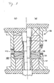
- a clamping area 12c ( Figs. 1(a) and 1(b) ) on an axial end portion of a hub main body (the other raceway ring member) 12 is made easy to be deformed plastically, so that an inner ring 16 can be locked on the hub main body 12 with good efficiency by clamping (bringing into tight contact) the clamping area 12c along a circumferential end portion 16s of the inner ring 16.
- the hub main body 12 may be worked through cold closed forging so that a root portion of a mounting flange 12a where a higher rotational bending strength is required is maintained relatively hard, while a relative softness is maintained in the clamping area 12c of the hub main body 12 where clamping is applied.
- a process for forming the hub main body 12 through cold closed forging will be described by reference to Fig. 2 .
- a cylindrical billet 20 made of a machine structural carbon steel (JISG4051) is prepared into which the material is spheroidized.
- the billet 20 is a solid material here because the hub main body 12 ( Fig. 1(b) ) for a driven wheel is considered, in the case of the hub main body 12 for a drive wheel ( Fig. 1(a) ), a hollow billet (not shown) may only have to be prepared.
- a portion 20m which is to constitute an outer circumferential surface 4m of the hub main body 12 and a portion 20n-2 which is to constitute a fitting surface 4n-2 on which an outer ring 16 is fitted are formed monolithically by, for example, drawing the billet 20 through cold closed forging.
- a portion 20b which is to constitute a stepped portion 12b may be formed monolithically between both the portions 20m, 20n-2.
- a portion 20c which is to constitute a clamping area 12c of the hub main body 12 is formed monolithically at the same time.
- the billet is diametrically contracted or diametrically expanded through cold closed forging in the portion 20c.
- the portion 20c which is to constitute the clamping area 12c can be held relatively soft by performing such a diametrically shrinking or diametrically expanding process on to the portion concerned.
- the portion 20c which is constitute the clamping area 12c is diametrically contracted or diametrically expanded, the portion can be thinned by such an extent, whereby the hardness in the portion 20c concerned can be weakened. Since the extent to which the portion is diametrically contracted or diametrically expanded is set depending on, for example, the configuration and/or size of the hub main body 12, the magnitude of clamping force exerted on to the portion 20c concerned and the like, no specific numerical limit value is given here.
- a portion 20s which is to constitute an inner ring raceway 4s, a portion 20n-1 which is to constitute a sliding surface 4n-1 of a lip seal 10a or on which the lip seal 10a slides, and a portion 20a which is to constitute a mounting flange 12a are formed monolithically by side extruding the billet 20 through cold closed forging.
- a portion 20d which is to constitute a positioning cylindrical portion 12d is also formed monolithically in such a manner as to continue along a circumferential direction at the same time as the portion 20a which is to constitute the mounting flange 12a is formed.
- the hardness of the portion (including the rood portion) 20a which is to constitute the mounting flange 12a becomes harder than the portion 20c which is to constitute the clamping portion 12c of the hub main body 12. This is a result from a difference in hardening produced in the billet 20.
- the resulting difference in tensile strength becomes about 17 to 33kgf/mm 2 , and the result was obtained which exhibited that the strength (hardness) of the mounting flange (including the root portion thereof) was increased over the clamping area.
- a product which is formed into the same configuration as the hub main body 12 shown in Fig. 1(b) can be completed with high accuracy.
- the overall configuration of the hub main body 12 which includes the side extruded mounting flange 12a takes a star shape.
- annealing is a process for removing residouble row stress and reducing the hardness by changing the mechanical properties of a material.
- HV50 the hardness difference of HV50 to 100 between the clamping area 2c and the mounting flange 12a (including the root portion thereof)
- the hardness of the billet 20 needs to be set in consideration of a residouble row hardness in the clamping area which is desired to be maintained after cold closed forging.
- the residouble row hardness of the clamping area 12c can be set arbitrarily in relation to, for example, a clamping force exerted on the clamping area 12c and the hardness of the mounting flange 12a (including the root portion thereof), no specific numerical limit value is given here.
- the hardness of the mounting flange 12a (including the root portion thereof) can be set higher than the hardness of the clamping area 12c of the hub main body 12.
- the hardness of the mounting flange 12a (including the root portion thereof) can be set Vickers hardness HV50 or more higher than the hardness of the clamping area 12c of the hub main body 12 before clamping.
- the outer ring 2 is disposed on the finished hub main body 12 in such a manner as to face the hub main body 12, and a plurality of rolling elements 6, 8 and seal members are assembled thereon.
- a clamping is applied to the clamping area 12c.
- the hardness of the clamping area 12c of the hub main body 12 before clamping is maintained softer than the mounting flange 12a (including the root portion thereof). Because of this, the clamping area 12c can easily be clamped (brought into tight contact) along the circumferential end portion 16s of the inner ring 16.
- the inner ring 16 can be locked on the hub main body 12 with good efficiency.
- the hub main body 12 of the embodiment no machining is given to a surface (including a bolt seat surface 14m on which a hub bolt 14 is to be seated) of the mounting flange 12a and the positioning cylindrical portion 12d, and they can be used as they are. Because of this, no conventional eccenricity occurs in which the centers of the mounting flange and the positioning cylindrical portion become out of alignment, whereby for example, the rotation balance of the hub 4 (the hub main body 12) is lost. By this, a constant rotation performance of the bearing unit can be maintained over a long period of time.
- the positioning cylindrical portion 12d which continues in the circumferential direction can be formed monolithically in a simple and quick fashion, whereby since the manufacturing efficiency of the hub main body 12 can be increased, a reduction in manufacturing costs can be realized.
- the strength of the root portion of the mounting flange 12a can be increased, a reduction in thickness of the root portion can be realized, and a reduction in weight of the hub main body 12 can be realized by such an extent that the thickness is reduced, whereby since the unsprung load can be reduced, the running stability and controllability of the wheel can be increased.
- a heat treatment and grinding are preferably given to the sliding surface 4n-1 on which the lip seal 10a slides, the inner ring raceway 4s and the fitting surface 4n-2 on which the inner ring 16 fits.
- a quenching and tempering treatment through electromagnetic induction may be applied to an area extending from the sliding surface 4n-1 to the inner ring 16 fitting surface 4n-2 via the inner ring raceway 4s and a stepped portion 12b of the outer circumferential surface 4m.
- the finished article in the heating process through electromagnetic induction, for example, when a high-frequency current is caused to flow through a coil to produce a high-frequency magnetic flux around the coil in such a state that the finished article (the hub main body 12) disposed in the coil, the finished article (the hub main body 12) can be heated by the action of induction then. As this occurs, the portion so heated is quenched by a cooling agent (for example, water), whereby quenching is given. Following this, the finished article (the hub main body 12) is heated and thereafter is cooled, whereby tempering is given.
- a cooling agent for example, water
- the finished article (the hub main body 12) can be uniformly quench hardened.
- the hub main body 12 ( Fig. 1(a) ) for a drive wheel which is formed of a hollow billet (not shown)
- the heat capacities of the portions become constant. Because of this, the depth to which quench hardening is attained is stabilized, thereby making it possible to secure a uniform strength over the whole of the hub main body 12.
- the bearing unit of third generation is considered, the invention is not limited thereto, and hence, for example, the invention can be applied to a bearing unit of second and half generation shown in Figs. 3(a) and 3(b).
- Fig. 3(a) shows a bearing unit for a drive wheel
- Fig. 3(b) shows a bearing unit for a driven wheel.
- the bearing unit of second and half generation is configured basically the same as the bearing unit of third generation that has been described above, double row inner rings 16 are fitted on a hub main body 12.
- the double row inner rings 16 can be locked on the hub main body 12 with good efficiency.
Landscapes
- Engineering & Computer Science (AREA)
- Mechanical Engineering (AREA)
- General Engineering & Computer Science (AREA)
- Manufacturing & Machinery (AREA)
- Rolling Contact Bearings (AREA)
Applications Claiming Priority (5)
| Application Number | Priority Date | Filing Date | Title |
|---|---|---|---|
| JP2006214744A JP5103819B2 (ja) | 2006-08-07 | 2006-08-07 | 転がり軸受ユニット用軌道輪部材の製造方法 |
| JP2006224553A JP5168852B2 (ja) | 2006-08-21 | 2006-08-21 | 軸受ユニット |
| JP2006224554A JP5050446B2 (ja) | 2006-08-21 | 2006-08-21 | 軸受ユニット |
| JP2006226849A JP5103828B2 (ja) | 2006-08-23 | 2006-08-23 | 車輪用軸受ユニット及びその車輪用軸受ユニットにおけるフランジ付きの内方部材あるいは外方部材の製造方法 |
| EP07792081.7A EP2050583B1 (fr) | 2006-08-07 | 2007-08-07 | Element de bague a chemin de roulement pour unite de palier, unite de palier et procede et dispositif de production d'element de bague a chemin de roulement pour unite de palier |
Related Parent Applications (1)
| Application Number | Title | Priority Date | Filing Date |
|---|---|---|---|
| EP07792081.7 Division | 2007-08-07 |
Publications (1)
| Publication Number | Publication Date |
|---|---|
| EP2599642A1 true EP2599642A1 (fr) | 2013-06-05 |
Family
ID=39032969
Family Applications (4)
| Application Number | Title | Priority Date | Filing Date |
|---|---|---|---|
| EP07792081.7A Active EP2050583B1 (fr) | 2006-08-07 | 2007-08-07 | Element de bague a chemin de roulement pour unite de palier, unite de palier et procede et dispositif de production d'element de bague a chemin de roulement pour unite de palier |
| EP13000962.4A Active EP2599640B1 (fr) | 2006-08-07 | 2007-08-07 | Unité de palier et procédé de production d'un élément de bague à chemin de roulement pour unité de palier |
| EP13000964.0A Withdrawn EP2599642A1 (fr) | 2006-08-07 | 2007-08-07 | Unité de palier |
| EP13000963.2A Active EP2599641B1 (fr) | 2006-08-07 | 2007-08-07 | Unité d'élément de bague à chemin de roulement, unité de palier et procédé et appareil de fabrication d'un élément de bague à chemin de roulement de l'unité de roulement |
Family Applications Before (2)
| Application Number | Title | Priority Date | Filing Date |
|---|---|---|---|
| EP07792081.7A Active EP2050583B1 (fr) | 2006-08-07 | 2007-08-07 | Element de bague a chemin de roulement pour unite de palier, unite de palier et procede et dispositif de production d'element de bague a chemin de roulement pour unite de palier |
| EP13000962.4A Active EP2599640B1 (fr) | 2006-08-07 | 2007-08-07 | Unité de palier et procédé de production d'un élément de bague à chemin de roulement pour unité de palier |
Family Applications After (1)
| Application Number | Title | Priority Date | Filing Date |
|---|---|---|---|
| EP13000963.2A Active EP2599641B1 (fr) | 2006-08-07 | 2007-08-07 | Unité d'élément de bague à chemin de roulement, unité de palier et procédé et appareil de fabrication d'un élément de bague à chemin de roulement de l'unité de roulement |
Country Status (3)
| Country | Link |
|---|---|
| US (1) | US20090263065A1 (fr) |
| EP (4) | EP2050583B1 (fr) |
| WO (1) | WO2008018439A1 (fr) |
Families Citing this family (23)
| Publication number | Priority date | Publication date | Assignee | Title |
|---|---|---|---|---|
| US8919171B2 (en) * | 2005-03-03 | 2014-12-30 | Nippon Steel & Sumitomo Metal Corporation | Method for three-dimensionally bending workpiece and bent product |
| US8863565B2 (en) * | 2005-03-03 | 2014-10-21 | Nippon Steel & Sumitomo Metal Corporation | Three-dimensionally bending machine, bending-equipment line, and bent product |
| JP5365831B2 (ja) * | 2008-04-25 | 2013-12-11 | 株式会社ジェイテクト | 車輪用転がり軸受装置の熱処理方法と内軸の冷却装置 |
| JP2010089522A (ja) * | 2008-10-03 | 2010-04-22 | Nsk Ltd | 車輪支持用転がり軸受ユニットの製造方法 |
| JP2010188827A (ja) * | 2009-02-17 | 2010-09-02 | Jtekt Corp | 車輪用軸受装置とその製造方法 |
| JP2010188830A (ja) * | 2009-02-17 | 2010-09-02 | Jtekt Corp | 車輪用軸受装置 |
| JP5423033B2 (ja) * | 2009-02-17 | 2014-02-19 | 株式会社ジェイテクト | 車輪用軸受装置の製造方法 |
| US8511903B2 (en) * | 2009-02-17 | 2013-08-20 | Jtekt Corporation | Wheel bearing device and manufacturing method therefor |
| US20100210369A1 (en) * | 2009-02-17 | 2010-08-19 | Jtekt Corporation | Wheel bearing device and manufacturing method therefor |
| CN102069373B (zh) * | 2010-11-23 | 2012-07-25 | 江苏速升自动化装备股份有限公司 | 液压压紧装置 |
| JP2012183934A (ja) * | 2011-03-07 | 2012-09-27 | Jtekt Corp | 車輪用転がり軸受装置の軸部材 |
| JP2012197070A (ja) * | 2011-03-07 | 2012-10-18 | Jtekt Corp | 車輪用転がり軸受装置の製造方法及び車輪用転がり軸受装置 |
| DE102011005326A1 (de) | 2011-03-10 | 2012-09-13 | Schaeffler Technologies Gmbh & Co. Kg | Verfahren zur Herstellung eines Lagerringes, insbesondere für ein Kegelrollenlager |
| JP6101004B2 (ja) * | 2012-04-20 | 2017-03-22 | Ntn株式会社 | 車輪用軸受装置およびその製造方法 |
| JP2014008510A (ja) * | 2012-06-28 | 2014-01-20 | Jtekt Corp | 車輪用軸受装置の製造方法及び車輪用軸受装置 |
| JP6311414B2 (ja) * | 2014-04-07 | 2018-04-18 | 日本精工株式会社 | 外向フランジ部付金属製部材の製造方法、車輪支持用転がり軸受ユニットの製造方法、及び、自動車の製造方法 |
| DE102016121412A1 (de) * | 2016-11-09 | 2018-05-09 | Robert Bosch Gmbh | Festlager und Lenkgetriebe |
| CN109536689B (zh) * | 2018-12-28 | 2020-04-21 | 洛阳轴承研究所有限公司 | 一种轴承钢制零件的热加工工艺方法 |
| CN110628998B (zh) * | 2019-07-31 | 2020-09-01 | 武汉理工大学 | 一种精密轴承组件组织稳定化形变相变协同调控方法 |
| IT201900013584A1 (it) * | 2019-08-01 | 2021-02-01 | Skf Ab | Anello interno flangiato per cuscinetti mozzo ruota |
| ES2992230T3 (es) * | 2020-09-28 | 2024-12-10 | Cie Automotive Sa | Actuador mecánico |
| CN113477860B (zh) * | 2021-07-02 | 2022-06-07 | 重庆天力通科技开发有限公司 | 一种汽车零配件生产用锻压装置及其使用方法 |
| CN118905140B (zh) * | 2024-10-11 | 2024-12-10 | 成都迈特航空制造有限公司 | 一种钛合金内六角零件热镦成型模具及成型方法 |
Citations (5)
| Publication number | Priority date | Publication date | Assignee | Title |
|---|---|---|---|---|
| JP2003025803A (ja) | 2001-07-19 | 2003-01-29 | Koyo Seiko Co Ltd | 車軸用軸受装置 |
| US20050141798A1 (en) * | 2003-12-25 | 2005-06-30 | Makoto Okasaka | Bearing apparatus for a wheel of vehicle |
| JP2005256897A (ja) | 2004-03-10 | 2005-09-22 | Ntn Corp | 機械要素およびその製造方法 |
| JP2006111070A (ja) | 2004-10-13 | 2006-04-27 | Nsk Ltd | 車輪支持用ハブユニット、及び車輪支持用ハブユニットの軌道輪部材、並びにその製造方法 |
| JP2006142983A (ja) * | 2004-11-19 | 2006-06-08 | Nsk Ltd | 車輪支持用ハブユニット、及び車輪支持用ハブユニットの軌道輪部材、並びにその製造方法 |
Family Cites Families (20)
| Publication number | Priority date | Publication date | Assignee | Title |
|---|---|---|---|---|
| US2205876A (en) * | 1937-09-09 | 1940-06-25 | Phelps Langworthy E | Bearing |
| JP3526323B2 (ja) * | 1994-05-20 | 2004-05-10 | Ntn株式会社 | ハブユニット軸受外輪の製造方法 |
| JP2838680B2 (ja) * | 1996-04-19 | 1998-12-16 | 株式会社ゴーシュー | Abs用ロータを有する回転部材の製造方法 |
| EP0854303B1 (fr) * | 1997-01-17 | 2003-10-29 | Nsk Ltd | Ensemble de roulement pour supporter une roue d'un véhicule |
| JP3601537B2 (ja) * | 1997-08-28 | 2004-12-15 | 日本精工株式会社 | 車輪支持用転がり軸受ユニット |
| JP3989168B2 (ja) * | 2000-09-20 | 2007-10-10 | Ntn株式会社 | 車輪軸受装置 |
| DE60141438D1 (de) * | 2000-09-20 | 2010-04-15 | Ntn Toyo Bearing Co Ltd | Radlagervorrichtung |
| JP2003002003A (ja) * | 2001-06-26 | 2003-01-08 | Nsk Ltd | 車輪用軸受ユニット |
| CN100347459C (zh) * | 2002-07-15 | 2007-11-07 | 日本精工株式会社 | 车轮支撑用滚动轴承单元 |
| EP1603585A2 (fr) * | 2003-03-14 | 2005-12-14 | Bristol-Myers Squibb Company | Polynucleotide codant un nouveau variant de recepteur de hm74, hgprbmy74 couple a une proteine g humaine |
| JP4063722B2 (ja) * | 2003-06-11 | 2008-03-19 | Ntn株式会社 | 車輪用軸受装置 |
| JP4352927B2 (ja) * | 2004-02-20 | 2009-10-28 | 日本精工株式会社 | 車輪支持用ハブユニットを構成する軌道輪部材の製造方法 |
| JP2005354469A (ja) | 2004-06-11 | 2005-12-22 | Renesas Technology Corp | 画像処理装置及びプリンタ |
| JP2006063355A (ja) * | 2004-08-24 | 2006-03-09 | Nsk Ltd | 転がり軸受及びその軌道輪の製造方法 |
| EP1647418B1 (fr) * | 2004-10-13 | 2012-06-27 | Nsk Ltd. | Moyeu avec support de roue et bague de palier, et procédé de fabrication d'un tel moyeu |
| JP2006200700A (ja) * | 2005-01-24 | 2006-08-03 | Nsk Ltd | 車輪支持用転がり軸受装置 |
| JP2006214744A (ja) | 2005-02-01 | 2006-08-17 | Gunma Univ | バイオセンサ及びバイオセンサチップ |
| JP4335828B2 (ja) | 2005-02-17 | 2009-09-30 | ニチアス株式会社 | 耐火試験体構造および耐火試験方法 |
| JP4622571B2 (ja) | 2005-02-18 | 2011-02-02 | セイコーエプソン株式会社 | 液体噴射装置 |
| JP2006224553A (ja) | 2005-02-18 | 2006-08-31 | Fuji Photo Film Co Ltd | インクジェット用受像材料、その製造方法、及びそれを用いた画像形成方法 |
-
2007
- 2007-08-07 EP EP07792081.7A patent/EP2050583B1/fr active Active
- 2007-08-07 EP EP13000962.4A patent/EP2599640B1/fr active Active
- 2007-08-07 US US12/376,716 patent/US20090263065A1/en not_active Abandoned
- 2007-08-07 EP EP13000964.0A patent/EP2599642A1/fr not_active Withdrawn
- 2007-08-07 EP EP13000963.2A patent/EP2599641B1/fr active Active
- 2007-08-07 WO PCT/JP2007/065412 patent/WO2008018439A1/fr not_active Ceased
Patent Citations (5)
| Publication number | Priority date | Publication date | Assignee | Title |
|---|---|---|---|---|
| JP2003025803A (ja) | 2001-07-19 | 2003-01-29 | Koyo Seiko Co Ltd | 車軸用軸受装置 |
| US20050141798A1 (en) * | 2003-12-25 | 2005-06-30 | Makoto Okasaka | Bearing apparatus for a wheel of vehicle |
| JP2005256897A (ja) | 2004-03-10 | 2005-09-22 | Ntn Corp | 機械要素およびその製造方法 |
| JP2006111070A (ja) | 2004-10-13 | 2006-04-27 | Nsk Ltd | 車輪支持用ハブユニット、及び車輪支持用ハブユニットの軌道輪部材、並びにその製造方法 |
| JP2006142983A (ja) * | 2004-11-19 | 2006-06-08 | Nsk Ltd | 車輪支持用ハブユニット、及び車輪支持用ハブユニットの軌道輪部材、並びにその製造方法 |
Also Published As
| Publication number | Publication date |
|---|---|
| US20090263065A1 (en) | 2009-10-22 |
| EP2599641B1 (fr) | 2015-06-10 |
| EP2050583B1 (fr) | 2013-12-04 |
| EP2599640B1 (fr) | 2014-12-10 |
| EP2050583A4 (fr) | 2010-07-14 |
| WO2008018439A1 (fr) | 2008-02-14 |
| EP2050583A1 (fr) | 2009-04-22 |
| EP2599641A3 (fr) | 2013-08-07 |
| EP2599641A2 (fr) | 2013-06-05 |
| EP2599640A1 (fr) | 2013-06-05 |
Similar Documents
| Publication | Publication Date | Title |
|---|---|---|
| EP2599642A1 (fr) | Unité de palier | |
| CN101500823B (zh) | 轴承单元滚道环部件、轴承单元以及用于制造轴承单元滚道环部件的方法和设备 | |
| JP6523677B2 (ja) | 車輪用軸受装置のハブ輪および内方部材の製造方法 | |
| US9889493B2 (en) | Wheel bearing device with a clearance formed between the inner race and the hub wheel | |
| US20100239202A1 (en) | Double-row angular bearing, bearing device for wheel, method of producing outer race, and method of producing inner race | |
| JP5040108B2 (ja) | 車輪支持用転がり軸受ユニットを構成する軌道輪部材の製造方法 | |
| EP2754564B1 (fr) | Unité de moyeu léger avec des bagues de palier intégrées et son procédé de fabrication | |
| JP5359877B2 (ja) | 転がり軸受ユニット用軌道輪部材の製造方法 | |
| US8763255B2 (en) | Manufacturing method for wheel rolling bearing device, and wheel rolling bearing device | |
| JP5228343B2 (ja) | 車輪支持用複列転がり軸受ユニット及びその製造方法 | |
| EP2497583B1 (fr) | Procédé de fabrication d'un arbre pour moyeu de roue à roulement | |
| JP5050446B2 (ja) | 軸受ユニット | |
| JP2007145203A (ja) | 車輪用軸受装置 | |
| JP5168852B2 (ja) | 軸受ユニット | |
| EP2684626B1 (fr) | Procédé de fabrication pour dispositif de roulement à rouleaux de roue | |
| JP4961778B2 (ja) | 転がり軸受ユニット用軌道輪部材の製造方法 | |
| JP2015071183A (ja) | 車輪用軸受装置の外方部材の製造方法 | |
| JP2007016959A (ja) | 車輪支持用転がり軸受ユニットの外輪の製造方法 | |
| EP2684709A1 (fr) | Élément d'arbre pour dispositif de palier à roulement pour une roue | |
| JP2008036679A (ja) | 突出部付筒状部材の製造方法 | |
| JP2012184813A (ja) | 車輪用転がり軸受装置の軸部材とその製造方法 | |
| JP2023055544A (ja) | 車輪支持用転がり軸受ユニットの外輪の製造方法及び車輪支持用転がり軸受ユニット | |
| JP6311414B2 (ja) | 外向フランジ部付金属製部材の製造方法、車輪支持用転がり軸受ユニットの製造方法、及び、自動車の製造方法 | |
| EP2684711A1 (fr) | Dispositif de palier à roulement pour une roue |
Legal Events
| Date | Code | Title | Description |
|---|---|---|---|
| PUAI | Public reference made under article 153(3) epc to a published international application that has entered the european phase |
Free format text: ORIGINAL CODE: 0009012 |
|
| AC | Divisional application: reference to earlier application |
Ref document number: 2050583 Country of ref document: EP Kind code of ref document: P |
|
| AK | Designated contracting states |
Kind code of ref document: A1 Designated state(s): DE FR |
|
| STAA | Information on the status of an ep patent application or granted ep patent |
Free format text: STATUS: THE APPLICATION IS DEEMED TO BE WITHDRAWN |
|
| 18D | Application deemed to be withdrawn |
Effective date: 20131206 |