EP2599705A2 - Jambe de fourche télescopique - Google Patents
Jambe de fourche télescopique Download PDFInfo
- Publication number
- EP2599705A2 EP2599705A2 EP12186375.7A EP12186375A EP2599705A2 EP 2599705 A2 EP2599705 A2 EP 2599705A2 EP 12186375 A EP12186375 A EP 12186375A EP 2599705 A2 EP2599705 A2 EP 2599705A2
- Authority
- EP
- European Patent Office
- Prior art keywords
- piston
- telescopic fork
- fork leg
- tube
- damping system
- Prior art date
- Legal status (The legal status is an assumption and is not a legal conclusion. Google has not performed a legal analysis and makes no representation as to the accuracy of the status listed.)
- Granted
Links
Images
Classifications
-
- F—MECHANICAL ENGINEERING; LIGHTING; HEATING; WEAPONS; BLASTING
- F16—ENGINEERING ELEMENTS AND UNITS; GENERAL MEASURES FOR PRODUCING AND MAINTAINING EFFECTIVE FUNCTIONING OF MACHINES OR INSTALLATIONS; THERMAL INSULATION IN GENERAL
- F16F—SPRINGS; SHOCK-ABSORBERS; MEANS FOR DAMPING VIBRATION
- F16F9/00—Springs, vibration-dampers, shock-absorbers, or similarly-constructed movement-dampers using a fluid or the equivalent as damping medium
- F16F9/10—Springs, vibration-dampers, shock-absorbers, or similarly-constructed movement-dampers using a fluid or the equivalent as damping medium using liquid only; using a fluid of which the nature is immaterial
- F16F9/14—Devices with one or more members, e.g. pistons, vanes, moving to and fro in chambers and using throttling effect
- F16F9/16—Devices with one or more members, e.g. pistons, vanes, moving to and fro in chambers and using throttling effect involving only straight-line movement of the effective parts
- F16F9/18—Devices with one or more members, e.g. pistons, vanes, moving to and fro in chambers and using throttling effect involving only straight-line movement of the effective parts with a closed cylinder and a piston separating two or more working spaces therein
- F16F9/20—Devices with one or more members, e.g. pistons, vanes, moving to and fro in chambers and using throttling effect involving only straight-line movement of the effective parts with a closed cylinder and a piston separating two or more working spaces therein with the piston-rod extending through both ends of the cylinder, e.g. constant-volume dampers
-
- B—PERFORMING OPERATIONS; TRANSPORTING
- B62—LAND VEHICLES FOR TRAVELLING OTHERWISE THAN ON RAILS
- B62K—CYCLES; CYCLE FRAMES; CYCLE STEERING DEVICES; RIDER-OPERATED TERMINAL CONTROLS SPECIALLY ADAPTED FOR CYCLES; CYCLE AXLE SUSPENSIONS; CYCLE SIDECARS, FORECARS, OR THE LIKE
- B62K25/00—Axle suspensions
- B62K25/04—Axle suspensions for mounting axles resiliently on cycle frame or fork
- B62K25/06—Axle suspensions for mounting axles resiliently on cycle frame or fork with telescopic fork, e.g. including auxiliary rocking arms
- B62K25/08—Axle suspensions for mounting axles resiliently on cycle frame or fork with telescopic fork, e.g. including auxiliary rocking arms for front wheel
-
- F—MECHANICAL ENGINEERING; LIGHTING; HEATING; WEAPONS; BLASTING
- F16—ENGINEERING ELEMENTS AND UNITS; GENERAL MEASURES FOR PRODUCING AND MAINTAINING EFFECTIVE FUNCTIONING OF MACHINES OR INSTALLATIONS; THERMAL INSULATION IN GENERAL
- F16F—SPRINGS; SHOCK-ABSORBERS; MEANS FOR DAMPING VIBRATION
- F16F9/00—Springs, vibration-dampers, shock-absorbers, or similarly-constructed movement-dampers using a fluid or the equivalent as damping medium
- F16F9/10—Springs, vibration-dampers, shock-absorbers, or similarly-constructed movement-dampers using a fluid or the equivalent as damping medium using liquid only; using a fluid of which the nature is immaterial
- F16F9/14—Devices with one or more members, e.g. pistons, vanes, moving to and fro in chambers and using throttling effect
- F16F9/16—Devices with one or more members, e.g. pistons, vanes, moving to and fro in chambers and using throttling effect involving only straight-line movement of the effective parts
- F16F9/18—Devices with one or more members, e.g. pistons, vanes, moving to and fro in chambers and using throttling effect involving only straight-line movement of the effective parts with a closed cylinder and a piston separating two or more working spaces therein
- F16F9/185—Bitubular units
-
- F—MECHANICAL ENGINEERING; LIGHTING; HEATING; WEAPONS; BLASTING
- F16—ENGINEERING ELEMENTS AND UNITS; GENERAL MEASURES FOR PRODUCING AND MAINTAINING EFFECTIVE FUNCTIONING OF MACHINES OR INSTALLATIONS; THERMAL INSULATION IN GENERAL
- F16F—SPRINGS; SHOCK-ABSORBERS; MEANS FOR DAMPING VIBRATION
- F16F9/00—Springs, vibration-dampers, shock-absorbers, or similarly-constructed movement-dampers using a fluid or the equivalent as damping medium
- F16F9/32—Details
- F16F9/44—Means on or in the damper for manual or non-automatic adjustment; such means combined with temperature correction
- F16F9/46—Means on or in the damper for manual or non-automatic adjustment; such means combined with temperature correction allowing control from a distance, i.e. location of means for control input being remote from site of valves, e.g. on damper external wall
-
- F—MECHANICAL ENGINEERING; LIGHTING; HEATING; WEAPONS; BLASTING
- F16—ENGINEERING ELEMENTS AND UNITS; GENERAL MEASURES FOR PRODUCING AND MAINTAINING EFFECTIVE FUNCTIONING OF MACHINES OR INSTALLATIONS; THERMAL INSULATION IN GENERAL
- F16F—SPRINGS; SHOCK-ABSORBERS; MEANS FOR DAMPING VIBRATION
- F16F9/00—Springs, vibration-dampers, shock-absorbers, or similarly-constructed movement-dampers using a fluid or the equivalent as damping medium
- F16F9/32—Details
- F16F9/50—Special means providing automatic damping adjustment, i.e. self-adjustment of damping by particular sliding movements of a valve element, other than flexions or displacement of valve discs; Special means providing self-adjustment of spring characteristics
- F16F9/512—Means responsive to load action, i.e. static load on the damper or dynamic fluid pressure changes in the damper, e.g. due to changes in velocity
Definitions
- the present invention relates to a telescopic fork leg with damping system, comprising piston and.piston rod arrangements designed to perform longitudinal shift motions in a chamber provided with medium, which chamber is situated in a tubular part which is divided for the damping system.
- the telescopic fork leg is intended to be able to form part of, for example, a front fork arrangement for, inter alia, a motor cycle.
- Telescopic fork legs with damping system are previously known and, in this context, reference can be made to telescopic fork legs of this type which are sold on the open market. Reference can also be made to a telescopic fork which is sold under the designation FG 470 by the applicant for the present patent application.
- the known telescopic forks comprise outer and inner tubes which are mutually arranged for the telescoping function and which are fitted between mutually movable parts of the particular vehicle (for example motor cycle, car, motor scooter, etc.).
- the telescopic fork leg also comprises, inter alia, a main spring and fastening members and the damping system can operate with main piston, piston rod, valve arrangement, etc.
- telescopic forks of this kind there is a need to be able to achieve improved damping characteristics and for the dynamic conditions to be able to be made more independent of the damping values in question.
- the telescopic fork must be able to be easily usable in connection with the particular vehicle (motor cycle) and so, for example, adjustment facilities for an integral leak flow arrangement must be eminently simple and' individually configured for the compression and expansion motions in the fork.
- the adjustment of the leak flow in one direction shall not necessarily affect the adjustment of the leak flow in the other direction.
- the chamber for the telescopic fork is a critical parameter in connection with the particular vehicle. There is here a need to be able to integrate the telescoping and damping functions and to utilize the same components for these functions. It is also important to be able to reduce the number of components in the telescopic fork leg and, for example, to be able to eliminate a valve or valves which, in the prior art, is/are designed to handle the problem of an increase in medium volume due to occurring displacement.
- the valve arrangement (for example shims or shim assembly) for the damping piston should also be able to be assigned effective placements and must be able to be disposed wholly or partially in the main piston and/or wholly or partially beside the main piston (the damping piston).
- the object of the present invention is to solve the above-stated problems in whole or in part.
- the telescopic fork leg according to the invention can principally be deemed to be characterized in that the piston rod arrangement referred to in the introduction is designed so as in the chamber, with its parts present therein, to have substantially constant volume regardless of the shift motions and thereby to prevent substantial displacement creation and cause the medium to strive to assume and maintain a particular pressure, preferably a positive pressure, on the low-pressure side of the piston arrangement.
- the said pressure on the said low-pressure side is substantially independent of the nature of a valve system assigned to the piston arrangement.
- the said pressure can here be chosen equal to the pressure of the damping system.
- the main flow of the damping system passes via damping members, for example shims, on or in the piston arrangement.
- Preferably adjusting members are utilized, by means of which leak flow or leak flows is/are arranged so as to be able to be conducted around the piston arrangement.
- Leak flow passages can here be provided for both the compression motions and the return motions of the piston arrangement.
- a first adjusting member can be provided for adjustability of the leak flow in respect of the compression motions and a second adjusting member can be provided for adjustability of the leak flow in respect of the return motions. Adjustment of the leak flow for the compression motions is preferably realized without affecting the leak flow for the return motions, and vice versa.
- the piston rod arrangement can comprise piston rod parts extending from both sides of the piston arrangement and together through the whole of the chamber in the longitudinal direction thereof, regardless of the longitudinal shift position of the piston in the chamber. Alternatively, a continuous piston rod can be arranged such that it extends in the whole of the longitudinal direction of the chamber, irrespective of the length of the respective shift motion.
- a piston/main piston/damping piston belonging to the piston arrangement can be applied to the said piston rod.
- the adjusting members are arranged so as to be easily accessible from the outside of the telescopic fork leg.
- the telescopic fork and damping system functions can be integrated in full or in part and the damping system is preferably provided with a low-pressure point, at which a change in medium volume due to heat or cooling is designed to occur.
- the invention is preferably utilized for a short-stroke and relatively long telescopic fork leg. Further embodiments of the inventive concept emerge from the following subclaims and the description.
- the damping system can be provided with what is here referred to as positive pressure build-up, which forms the basis for the resolution of the problems referred to in the introduction.
- the external dimensions of the leg can be kept down and the various main and leak flows can be easily established to produce effective damping characteristics or good damping quality.
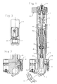
- the outer tube of the telescopic fork leg, with associated bushings is denoted by 1.
- an inner tube 2 which in the present case has a double function in that it constitutes the outer tube in the below-specified damping system.
- the reference numeral 3 represents a bottom piece and the reference 4 represents a spring (main spring).
- a piston rod 6 is provided for the transmission of damping force to the front fork.
- the reference numeral 7 shows a piston holder.
- a main piston or damping piston is denoted by 8.
- the piston is provided with continuous passages and shims or shim stacks which are placed at these and form a compression shim stack and a return shim stack.
- a piston rod for displacement out of the damping system is denoted by 9.
- the inner tube 10 of the damping system is provided with connecting ducts between the insides and the outsides in question.
- An extension tube 11 separates the damping system from the atmosphere.
- the telescopic fork leg also comprises an upper seal assembly 12, which seals between the piston rod and the inner tube of the damping system.
- a lower seal assembly 13 is included, which seals between the piston rod and the inner tube of the damping system.
- An outer seal assembly 14 seals between the inner tube of the damping system and the outer tube of the damping system.
- a valve housing is denoted by 15 and a gas container or accumulator by 16. Needle and mouthpiece in an adjusting member for adjusting return leak flows around the main piston are denoted by 17. In addition, a one-way valve 18 is included, arranged such that it can be opened only upon the establishment of a return leak flow around the piston 8. Needle and mouthpiece for adjusting compression leak flow around the main piston 8 are denoted by 19. A one-way valve (non-return valve) 20 can be opened only upon the establishment of a compression leak flow around the main piston.
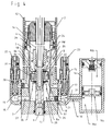
- needle and mouthpiece for an adjusting member for adjusting compression leak flow around the main piston 8 according to Figure 1 are denoted by 19.
- a one-way valve which is opened only by compression leak flow around the main piston 8 is denoted by 20.
- a low-pressure point in which the fork is connected to the gas container 8 is represented by 21.
- the damping system comprises a tubular part which forms the inner tube 10 of the damping system and which is here also referred to as the first tube.
- the inner tube 10 is provided with continuous (in the transverse direction) first passages.
- a gap between the inner tube 10 and the damping system outer tube 2 (also has the function of constituting the inner tube in the telescoping function) is denoted by 26. Connections are therefore established between the two sides of the piston 8 for the leak flows 27 (dashed arrows) in respect of compression and 28 (solid arrows) in respect of expansion or return.
- the compression leak flow 27 therefore leads from the side 8a of the piston, the inner chamber 29 formed by the inner tube 10, the passage (duct) 27, the low-pressure point 21, the adjusting member 22, the one-way valve 20, the gap 26, the passage 24 and the chamber 29 on the other side 8b of the piston 8.
- the second leak flow path leads from the chamber 29 on the piston side 8b, the passage 24, the gap 26, the adjusting member 23, the low-pressure point 21, the one-way valve 18, the passage 25 and to the chamber 29 on the bottom side 8a of the piston.
- the one-way valves 18 and 20 therefore produce the leak flow connections in the respective direction and the needles and seats of the adjusting members are individually adjustable.
- the valves 18 and 20, in a known manner, comprise a cone, a seat and a spring, which acts in one direction.
- the gas container has a chamber 16a for medium, for example hydraulic oil with additives, and a chamber 16b for compressible medium, for example gas.
- the spring function with gas can be replaced with mechanical springs, etc.
- the separating piston is denoted by 16c.
- the handling procedure is therefore valve-free (cf. prior art).
- the main flows through the piston 8 in both directions are symbolized with a dashed thicker arrow (compression) 32 and a solid thicker arrow (return) 33.
- the shim assemblies of the piston which are denoted by 8c and 8d, determine the nature of the damping system in a manner which is known per se and are placed at continuous passages 8e and 8f in the piston. Parts of or the whole of the main flow can alternatively be conducted on the side of the piston which is here provided with additional inner tubes/ducts/gaps (not shown).
- the adjusting members for the leak flows are arranged such that they are easily accessible from the outside of the fork and can be actuated, for example, manually by the use of tools (screwdriver, spanner, etc.).
- a piston rod 6 is utilized which, with parts, passes fully through the chamber 29 in the longitudinal direction thereof.
- the piston rod operates via a recess in the seal assembly 12.
- the piston rod is sealed with sealing members to prevent connection between the chamber 29 and the surroundings of the fork (the atmosphere).
- the parts in question of the piston rod run in the tube 11, here referred to as the third tube (see Figure 1 ).
- the piston rod parts in question are sealed against the inner wall of the tube 11 with sealing members which thereby seal off the damping system/the chamber 29 against the said surroundings (the atmosphere).
- the piston rod supports the piston 8, which is fixed in its longitudinal direction in a known manner by means of a lug and a retaining ring.
- the piston is provided in similarly known manner with a sliding-seal member, which is interactable with the inner face of the tube 10.
- the total length of the longitudinal shift motion is determined with interaction between stop parts on the piston rod arrangement and inner faces on the assembly 12 and the bottom piece 3.
- the piston rod is composed of piston rod parts mutually connected in a known manner.
- the external dimensions of the piston rod are chosen such that they substantially match on both sides of the piston in order to avoid displacement effect when the piston is shifted in the chamber 29.
- the parts which respectively enter and leave the chamber during compression and return shall correspond in terms of volume to the outgoing and ingoing parts of the piston rod in the shift motions, so that volume change is prevented for the medium.
- the arrangement means that the pressure on the low-pressure side is positively maintained and that, for example, cavitation problems do not arise. Very rapid shift motions can give rise to instantaneous lowering of the said pressure, but the arrangement constantly strives to rapidly return to and maintain the desired positive pressure on the low-pressure side.
- the telescopic fork is intended to be fastened to two mutually movable parts on a particular vehicle.
- a first part in the form of a wheel is symbolized with 34 and a second part in the form of a chassis is symbolized with 35.
- the fastening to the parts can be realized in a known manner.
- the main piston can alternatively be provided with two or more piston rod parts, which project from both sides of the piston.
- the inner tube of the telescoping function is also utilized as an outer tube in the damping function and is therefore included on the one hand as a strength-determining element, on the other hand as a medium-flow-determining element.
- the fork represents a relatively long fork, for example a fork of 0.5-1.0 m length, which operates with relatively short strokes, for example 0.2-0.4 m stroke length, the lower and higher values respectively of the length ranges being interdependent.
- One or more pistons 16 can be included.
- the gas container is integrated in the said bottom piece, in which the said low-pressure point is also placed.
- the adjusting members are disposed on the bottom piece.
Landscapes
- Engineering & Computer Science (AREA)
- General Engineering & Computer Science (AREA)
- Mechanical Engineering (AREA)
- Physics & Mathematics (AREA)
- Fluid Mechanics (AREA)
- Fluid-Damping Devices (AREA)
- Axle Suspensions And Sidecars For Cycles (AREA)
Applications Claiming Priority (2)
| Application Number | Priority Date | Filing Date | Title |
|---|---|---|---|
| SE0402960A SE529042C2 (sv) | 2004-12-06 | 2004-12-06 | Teleskopgaffelben |
| EP05445072.1A EP1666348B1 (fr) | 2004-12-06 | 2005-09-28 | Fourche téléscopique |
Related Parent Applications (3)
| Application Number | Title | Priority Date | Filing Date |
|---|---|---|---|
| EP05445072.1A Division-Into EP1666348B1 (fr) | 2004-12-06 | 2005-09-28 | Fourche téléscopique |
| EP05445072.1A Division EP1666348B1 (fr) | 2004-12-06 | 2005-09-28 | Fourche téléscopique |
| EP05445072.1 Division | 2005-09-28 |
Publications (3)
| Publication Number | Publication Date |
|---|---|
| EP2599705A2 true EP2599705A2 (fr) | 2013-06-05 |
| EP2599705A3 EP2599705A3 (fr) | 2018-01-24 |
| EP2599705B1 EP2599705B1 (fr) | 2019-11-27 |
Family
ID=33550588
Family Applications (2)
| Application Number | Title | Priority Date | Filing Date |
|---|---|---|---|
| EP12186375.7A Active EP2599705B1 (fr) | 2004-12-06 | 2005-09-28 | Jambe de fourche télescopique |
| EP05445072.1A Active EP1666348B1 (fr) | 2004-12-06 | 2005-09-28 | Fourche téléscopique |
Family Applications After (1)
| Application Number | Title | Priority Date | Filing Date |
|---|---|---|---|
| EP05445072.1A Active EP1666348B1 (fr) | 2004-12-06 | 2005-09-28 | Fourche téléscopique |
Country Status (3)
| Country | Link |
|---|---|
| US (1) | US7377372B2 (fr) |
| EP (2) | EP2599705B1 (fr) |
| SE (1) | SE529042C2 (fr) |
Families Citing this family (12)
| Publication number | Priority date | Publication date | Assignee | Title |
|---|---|---|---|---|
| SE531829C2 (sv) * | 2007-01-10 | 2009-08-18 | Oehlins Racing Ab | Framgaffel med tätningsfunktion |
| JP2009008152A (ja) * | 2007-06-27 | 2009-01-15 | Showa Corp | 油圧緩衝器 |
| IT1399514B1 (it) * | 2010-04-23 | 2013-04-19 | Crc Ct Ricerche Cagiva S A Ora Crc Ct Ricerche Castiglioni S R L | Motocicletta o similare con forcella anteriore modificabile nelle sue caratteristiche operative |
| EP2479096B1 (fr) | 2011-01-21 | 2013-04-24 | WP Performance Systems GmbH | Jambe de fourche à ressort télescopique et fourche à ressort télescopique en étant équipée |
| DE102011000280B4 (de) | 2011-01-21 | 2014-10-30 | Wp Performance Systems Gmbh | Teleskopfedergabelbein mit Ausgleichsvolumen für Dämpfungsfluid |
| US9897310B2 (en) * | 2015-04-29 | 2018-02-20 | Mudassir Ahmed | Effervescent atomizer with gas injection at reduced pressures |
| US9969231B2 (en) * | 2015-07-15 | 2018-05-15 | GM Global Technology Operations LLC | Damper assembly and a method of forming the damper assembly |
| EP3409972A1 (fr) * | 2017-06-01 | 2018-12-05 | Öhlins Racing AB | Jambe de fourche avant télescopique sous pression, fourche avant et véhicule |
| EP3594526B1 (fr) * | 2018-07-13 | 2026-05-06 | Öhlins Group AB | Régulateur de raideur de ressort |
| US20230027763A1 (en) * | 2021-07-21 | 2023-01-26 | Fox Factory, Inc. | Internal floating piston |
| DE102021128587A1 (de) | 2021-11-03 | 2023-05-04 | Bayerische Motoren Werke Aktiengesellschaft | Dämpfer für ein Gabelbein eines einspurigen Kraftfahrzeugs |
| JP2024053137A (ja) * | 2022-10-03 | 2024-04-15 | 日立Astemo株式会社 | フロントフォーク |
Family Cites Families (21)
| Publication number | Priority date | Publication date | Assignee | Title |
|---|---|---|---|---|
| US2264856A (en) * | 1939-10-24 | 1941-12-02 | Leslie Claude Howe | Hydraulic line spooler |
| US2334115A (en) * | 1941-06-05 | 1943-11-09 | Smith & Sons Ltd S | Hydraulic apparatus |
| DE2456286A1 (de) * | 1974-11-28 | 1976-08-12 | Peddinghaus Carl Ullrich Dr | Hydropneumatischer schwingungsdaempfer |
| NL169216C (nl) * | 1977-12-12 | 1982-06-16 | Itt | Inrichting voor het verlagen van de druk op de zuigerstangpakking van een hydraulische telescopische schokdemper. |
| US4280600A (en) * | 1979-07-02 | 1981-07-28 | Otis Elevator Company | Self-refilling hydraulic actuator |
| JPS60151439A (ja) | 1984-01-18 | 1985-08-09 | Kayaba Ind Co Ltd | ステアリングダンパ |
| SE438990B (sv) * | 1984-06-21 | 1985-05-28 | Saab Scania Ab | Arrangemang for dempning av vexlingsrorelser vid en mekanisk synkroniserad flerstegsvexellada |
| JPH01172648A (ja) * | 1987-12-28 | 1989-07-07 | Toyota Motor Corp | ショックアブソーバ |
| US5107970A (en) * | 1991-04-17 | 1992-04-28 | Monroe Auto Equipment Company | High pressure sealing system and method |
| US5347771A (en) * | 1991-06-20 | 1994-09-20 | Kajima Corporation | High damping device for seismic response controlled structure |
| US5662046A (en) * | 1993-12-14 | 1997-09-02 | Hansen Inc. | Method and apparatus for controlling railway truck hunting and a railway car body supported thereby |
| ZA948197B (en) | 1993-12-14 | 1996-04-18 | Hansen Inc | Method and apparatus for controlling railway truck hunting and a railway car body supported thereby |
| JP3651144B2 (ja) | 1996-10-25 | 2005-05-25 | 鹿島建設株式会社 | 制震用オイルダンパ |
| JP3728648B2 (ja) * | 1998-07-15 | 2005-12-21 | カヤバ工業株式会社 | フロントフォーク |
| DE19922838B4 (de) | 1999-05-19 | 2004-11-04 | Zf Sachs Ag | Schwingungsdämpfer |
| FR2804188B1 (fr) * | 2000-01-26 | 2002-05-03 | Dld Internat | Amortisseur a haut pouvoir dissipatif |
| GB0004649D0 (en) * | 2000-02-29 | 2000-04-19 | Gkn Westland Helicopters Ltd | Vibration damping apparatus |
| WO2002012750A2 (fr) * | 2000-08-03 | 2002-02-14 | Lord Corporation | Mecanisme de reglage en hauteur |
| JP3873192B2 (ja) * | 2003-03-27 | 2007-01-24 | カヤバ工業株式会社 | ダンパ内蔵型フロントフォーク |
| FR2853708B1 (fr) | 2003-04-09 | 2005-05-27 | Goodrich Actuation Systems | Dispositif de realimentation des chambres d'un verin hydraulique |
| SE531829C2 (sv) * | 2007-01-10 | 2009-08-18 | Oehlins Racing Ab | Framgaffel med tätningsfunktion |
-
2004
- 2004-12-06 SE SE0402960A patent/SE529042C2/sv not_active IP Right Cessation
-
2005
- 2005-09-28 EP EP12186375.7A patent/EP2599705B1/fr active Active
- 2005-09-28 EP EP05445072.1A patent/EP1666348B1/fr active Active
- 2005-12-05 US US11/293,192 patent/US7377372B2/en active Active
Non-Patent Citations (1)
| Title |
|---|
| None |
Also Published As
| Publication number | Publication date |
|---|---|
| US20060118374A1 (en) | 2006-06-08 |
| SE0402960D0 (sv) | 2004-12-06 |
| US7377372B2 (en) | 2008-05-27 |
| EP1666348B1 (fr) | 2019-11-27 |
| EP1666348A2 (fr) | 2006-06-07 |
| EP2599705A3 (fr) | 2018-01-24 |
| SE0402960L (sv) | 2006-06-07 |
| SE529042C2 (sv) | 2007-04-17 |
| EP1666348A3 (fr) | 2010-02-17 |
| EP2599705B1 (fr) | 2019-11-27 |
Similar Documents
| Publication | Publication Date | Title |
|---|---|---|
| JP4840557B2 (ja) | 減衰力調整式油圧緩衝器 | |
| CN102574440B (zh) | 具有数字阀的阻尼器 | |
| JP4038654B2 (ja) | 減衰力調整式油圧緩衝器 | |
| EP2599705B1 (fr) | Jambe de fourche télescopique | |
| JP5785510B2 (ja) | 緩衝器のバルブ構造 | |
| US7766138B2 (en) | Arrangement for telescopic fork leg with parallel damping | |
| CA2627817C (fr) | Amortisseur hydraulique de type monocylindre pour vehicule | |
| JP2008267489A (ja) | 流体圧緩衝器 | |
| US8517153B2 (en) | Suspension damping valve | |
| CN115885118A (zh) | 缓冲器 | |
| JP2009074562A (ja) | 緩衝器 | |
| US6648310B2 (en) | Shock absorber | |
| EP1555199A1 (fr) | Fourche avant de motocyclette | |
| US20080115663A1 (en) | Vibration damper with amplitude-selective damping force | |
| JP5106347B2 (ja) | 液圧緩衝器 | |
| CN109863327B (zh) | 阀组 | |
| JPH08135714A (ja) | 液圧緩衝装置 | |
| JP2007321864A (ja) | 減衰力調整式油圧緩衝器 | |
| JP4636299B2 (ja) | 油圧緩衝器 | |
| JP6523848B2 (ja) | フロントフォーク | |
| JP2003247584A (ja) | フロントフォーク | |
| EP3848610A1 (fr) | Amortisseur à ressort à gaz et sans joints gaz à gaz | |
| JP5106321B2 (ja) | 単筒型液圧緩衝器 | |
| JP2007263287A (ja) | 油圧緩衝器 | |
| JP2003254374A (ja) | 油圧緩衝器 |
Legal Events
| Date | Code | Title | Description |
|---|---|---|---|
| PUAI | Public reference made under article 153(3) epc to a published international application that has entered the european phase |
Free format text: ORIGINAL CODE: 0009012 |
|
| AC | Divisional application: reference to earlier application |
Ref document number: 1666348 Country of ref document: EP Kind code of ref document: P |
|
| AK | Designated contracting states |
Kind code of ref document: A2 Designated state(s): AT BE BG CH CY CZ DE DK EE ES FI FR GB GR HU IE IS IT LI LT LU LV MC NL PL PT RO SE SI SK TR |
|
| PUAL | Search report despatched |
Free format text: ORIGINAL CODE: 0009013 |
|
| AK | Designated contracting states |
Kind code of ref document: A3 Designated state(s): AT BE BG CH CY CZ DE DK EE ES FI FR GB GR HU IE IS IT LI LT LU LV MC NL PL PT RO SE SI SK TR |
|
| RIC1 | Information provided on ipc code assigned before grant |
Ipc: F16F 9/512 20060101ALI20171221BHEP Ipc: F16F 9/20 20060101ALI20171221BHEP Ipc: B62K 25/08 20060101AFI20171221BHEP Ipc: F16F 9/44 20060101ALI20171221BHEP Ipc: F16F 9/18 20060101ALI20171221BHEP |
|
| STAA | Information on the status of an ep patent application or granted ep patent |
Free format text: STATUS: REQUEST FOR EXAMINATION WAS MADE |
|
| 17P | Request for examination filed |
Effective date: 20180724 |
|
| RBV | Designated contracting states (corrected) |
Designated state(s): AT BE BG CH CY CZ DE DK EE ES FI FR GB GR HU IE IS IT LI LT LU LV MC NL PL PT RO SE SI SK TR |
|
| RIC1 | Information provided on ipc code assigned before grant |
Ipc: F16F 9/20 20060101ALI20190523BHEP Ipc: F16F 9/44 20060101ALI20190523BHEP Ipc: F16F 9/18 20060101ALI20190523BHEP Ipc: F16F 9/512 20060101ALI20190523BHEP Ipc: B62K 25/08 20060101AFI20190523BHEP |
|
| GRAP | Despatch of communication of intention to grant a patent |
Free format text: ORIGINAL CODE: EPIDOSNIGR1 |
|
| STAA | Information on the status of an ep patent application or granted ep patent |
Free format text: STATUS: GRANT OF PATENT IS INTENDED |
|
| INTG | Intention to grant announced |
Effective date: 20190704 |
|
| GRAS | Grant fee paid |
Free format text: ORIGINAL CODE: EPIDOSNIGR3 |
|
| GRAA | (expected) grant |
Free format text: ORIGINAL CODE: 0009210 |
|
| STAA | Information on the status of an ep patent application or granted ep patent |
Free format text: STATUS: THE PATENT HAS BEEN GRANTED |
|
| AC | Divisional application: reference to earlier application |
Ref document number: 1666348 Country of ref document: EP Kind code of ref document: P |
|
| AK | Designated contracting states |
Kind code of ref document: B1 Designated state(s): AT BE BG CH CY CZ DE DK EE ES FI FR GB GR HU IE IS IT LI LT LU LV MC NL PL PT RO SE SI SK TR |
|
| REG | Reference to a national code |
Ref country code: GB Ref legal event code: FG4D |
|
| REG | Reference to a national code |
Ref country code: CH Ref legal event code: EP |
|
| REG | Reference to a national code |
Ref country code: DE Ref legal event code: R096 Ref document number: 602005056455 Country of ref document: DE |
|
| REG | Reference to a national code |
Ref country code: AT Ref legal event code: REF Ref document number: 1206363 Country of ref document: AT Kind code of ref document: T Effective date: 20191215 |
|
| REG | Reference to a national code |
Ref country code: IE Ref legal event code: FG4D |
|
| REG | Reference to a national code |
Ref country code: NL Ref legal event code: MP Effective date: 20191127 |
|
| REG | Reference to a national code |
Ref country code: LT Ref legal event code: MG4D |
|
| PG25 | Lapsed in a contracting state [announced via postgrant information from national office to epo] |
Ref country code: SE Free format text: LAPSE BECAUSE OF FAILURE TO SUBMIT A TRANSLATION OF THE DESCRIPTION OR TO PAY THE FEE WITHIN THE PRESCRIBED TIME-LIMIT Effective date: 20191127 Ref country code: NL Free format text: LAPSE BECAUSE OF FAILURE TO SUBMIT A TRANSLATION OF THE DESCRIPTION OR TO PAY THE FEE WITHIN THE PRESCRIBED TIME-LIMIT Effective date: 20191127 Ref country code: LV Free format text: LAPSE BECAUSE OF FAILURE TO SUBMIT A TRANSLATION OF THE DESCRIPTION OR TO PAY THE FEE WITHIN THE PRESCRIBED TIME-LIMIT Effective date: 20191127 Ref country code: BG Free format text: LAPSE BECAUSE OF FAILURE TO SUBMIT A TRANSLATION OF THE DESCRIPTION OR TO PAY THE FEE WITHIN THE PRESCRIBED TIME-LIMIT Effective date: 20200227 Ref country code: FI Free format text: LAPSE BECAUSE OF FAILURE TO SUBMIT A TRANSLATION OF THE DESCRIPTION OR TO PAY THE FEE WITHIN THE PRESCRIBED TIME-LIMIT Effective date: 20191127 Ref country code: GR Free format text: LAPSE BECAUSE OF FAILURE TO SUBMIT A TRANSLATION OF THE DESCRIPTION OR TO PAY THE FEE WITHIN THE PRESCRIBED TIME-LIMIT Effective date: 20200228 Ref country code: LT Free format text: LAPSE BECAUSE OF FAILURE TO SUBMIT A TRANSLATION OF THE DESCRIPTION OR TO PAY THE FEE WITHIN THE PRESCRIBED TIME-LIMIT Effective date: 20191127 Ref country code: ES Free format text: LAPSE BECAUSE OF FAILURE TO SUBMIT A TRANSLATION OF THE DESCRIPTION OR TO PAY THE FEE WITHIN THE PRESCRIBED TIME-LIMIT Effective date: 20191127 |
|
| PG25 | Lapsed in a contracting state [announced via postgrant information from national office to epo] |
Ref country code: IS Free format text: LAPSE BECAUSE OF FAILURE TO SUBMIT A TRANSLATION OF THE DESCRIPTION OR TO PAY THE FEE WITHIN THE PRESCRIBED TIME-LIMIT Effective date: 20200327 |
|
| PG25 | Lapsed in a contracting state [announced via postgrant information from national office to epo] |
Ref country code: RO Free format text: LAPSE BECAUSE OF FAILURE TO SUBMIT A TRANSLATION OF THE DESCRIPTION OR TO PAY THE FEE WITHIN THE PRESCRIBED TIME-LIMIT Effective date: 20191127 Ref country code: CZ Free format text: LAPSE BECAUSE OF FAILURE TO SUBMIT A TRANSLATION OF THE DESCRIPTION OR TO PAY THE FEE WITHIN THE PRESCRIBED TIME-LIMIT Effective date: 20191127 Ref country code: DK Free format text: LAPSE BECAUSE OF FAILURE TO SUBMIT A TRANSLATION OF THE DESCRIPTION OR TO PAY THE FEE WITHIN THE PRESCRIBED TIME-LIMIT Effective date: 20191127 Ref country code: PT Free format text: LAPSE BECAUSE OF FAILURE TO SUBMIT A TRANSLATION OF THE DESCRIPTION OR TO PAY THE FEE WITHIN THE PRESCRIBED TIME-LIMIT Effective date: 20200419 Ref country code: EE Free format text: LAPSE BECAUSE OF FAILURE TO SUBMIT A TRANSLATION OF THE DESCRIPTION OR TO PAY THE FEE WITHIN THE PRESCRIBED TIME-LIMIT Effective date: 20191127 |
|
| REG | Reference to a national code |
Ref country code: DE Ref legal event code: R097 Ref document number: 602005056455 Country of ref document: DE |
|
| PG25 | Lapsed in a contracting state [announced via postgrant information from national office to epo] |
Ref country code: SK Free format text: LAPSE BECAUSE OF FAILURE TO SUBMIT A TRANSLATION OF THE DESCRIPTION OR TO PAY THE FEE WITHIN THE PRESCRIBED TIME-LIMIT Effective date: 20191127 |
|
| REG | Reference to a national code |
Ref country code: AT Ref legal event code: MK05 Ref document number: 1206363 Country of ref document: AT Kind code of ref document: T Effective date: 20191127 |
|
| PLBE | No opposition filed within time limit |
Free format text: ORIGINAL CODE: 0009261 |
|
| STAA | Information on the status of an ep patent application or granted ep patent |
Free format text: STATUS: NO OPPOSITION FILED WITHIN TIME LIMIT |
|
| PGFP | Annual fee paid to national office [announced via postgrant information from national office to epo] |
Ref country code: DE Payment date: 20200819 Year of fee payment: 16 Ref country code: GB Payment date: 20200819 Year of fee payment: 16 |
|
| 26N | No opposition filed |
Effective date: 20200828 |
|
| PG25 | Lapsed in a contracting state [announced via postgrant information from national office to epo] |
Ref country code: AT Free format text: LAPSE BECAUSE OF FAILURE TO SUBMIT A TRANSLATION OF THE DESCRIPTION OR TO PAY THE FEE WITHIN THE PRESCRIBED TIME-LIMIT Effective date: 20191127 Ref country code: SI Free format text: LAPSE BECAUSE OF FAILURE TO SUBMIT A TRANSLATION OF THE DESCRIPTION OR TO PAY THE FEE WITHIN THE PRESCRIBED TIME-LIMIT Effective date: 20191127 Ref country code: PL Free format text: LAPSE BECAUSE OF FAILURE TO SUBMIT A TRANSLATION OF THE DESCRIPTION OR TO PAY THE FEE WITHIN THE PRESCRIBED TIME-LIMIT Effective date: 20191127 |
|
| PG25 | Lapsed in a contracting state [announced via postgrant information from national office to epo] |
Ref country code: IT Free format text: LAPSE BECAUSE OF FAILURE TO SUBMIT A TRANSLATION OF THE DESCRIPTION OR TO PAY THE FEE WITHIN THE PRESCRIBED TIME-LIMIT Effective date: 20191127 |
|
| PG25 | Lapsed in a contracting state [announced via postgrant information from national office to epo] |
Ref country code: MC Free format text: LAPSE BECAUSE OF FAILURE TO SUBMIT A TRANSLATION OF THE DESCRIPTION OR TO PAY THE FEE WITHIN THE PRESCRIBED TIME-LIMIT Effective date: 20191127 |
|
| REG | Reference to a national code |
Ref country code: CH Ref legal event code: PL |
|
| REG | Reference to a national code |
Ref country code: BE Ref legal event code: MM Effective date: 20200930 |
|
| PG25 | Lapsed in a contracting state [announced via postgrant information from national office to epo] |
Ref country code: LU Free format text: LAPSE BECAUSE OF NON-PAYMENT OF DUE FEES Effective date: 20200928 |
|
| PG25 | Lapsed in a contracting state [announced via postgrant information from national office to epo] |
Ref country code: FR Free format text: LAPSE BECAUSE OF NON-PAYMENT OF DUE FEES Effective date: 20200930 |
|
| PG25 | Lapsed in a contracting state [announced via postgrant information from national office to epo] |
Ref country code: BE Free format text: LAPSE BECAUSE OF NON-PAYMENT OF DUE FEES Effective date: 20200930 Ref country code: CH Free format text: LAPSE BECAUSE OF NON-PAYMENT OF DUE FEES Effective date: 20200930 Ref country code: IE Free format text: LAPSE BECAUSE OF NON-PAYMENT OF DUE FEES Effective date: 20200928 Ref country code: LI Free format text: LAPSE BECAUSE OF NON-PAYMENT OF DUE FEES Effective date: 20200930 |
|
| REG | Reference to a national code |
Ref country code: DE Ref legal event code: R119 Ref document number: 602005056455 Country of ref document: DE |
|
| GBPC | Gb: european patent ceased through non-payment of renewal fee |
Effective date: 20210928 |
|
| PG25 | Lapsed in a contracting state [announced via postgrant information from national office to epo] |
Ref country code: TR Free format text: LAPSE BECAUSE OF FAILURE TO SUBMIT A TRANSLATION OF THE DESCRIPTION OR TO PAY THE FEE WITHIN THE PRESCRIBED TIME-LIMIT Effective date: 20191127 Ref country code: CY Free format text: LAPSE BECAUSE OF FAILURE TO SUBMIT A TRANSLATION OF THE DESCRIPTION OR TO PAY THE FEE WITHIN THE PRESCRIBED TIME-LIMIT Effective date: 20191127 |
|
| PG25 | Lapsed in a contracting state [announced via postgrant information from national office to epo] |
Ref country code: GB Free format text: LAPSE BECAUSE OF NON-PAYMENT OF DUE FEES Effective date: 20210928 Ref country code: DE Free format text: LAPSE BECAUSE OF NON-PAYMENT OF DUE FEES Effective date: 20220401 |