EP2600081A1 - Systeme de conditionnement d'air et d'alimentation en eau chaude - Google Patents
Systeme de conditionnement d'air et d'alimentation en eau chaude Download PDFInfo
- Publication number
- EP2600081A1 EP2600081A1 EP10855316.5A EP10855316A EP2600081A1 EP 2600081 A1 EP2600081 A1 EP 2600081A1 EP 10855316 A EP10855316 A EP 10855316A EP 2600081 A1 EP2600081 A1 EP 2600081A1
- Authority
- EP
- European Patent Office
- Prior art keywords
- hot
- water supply
- air conditioning
- heat exchanger
- refrigerant
- Prior art date
- Legal status (The legal status is an assumption and is not a legal conclusion. Google has not performed a legal analysis and makes no representation as to the accuracy of the status listed.)
- Withdrawn
Links
- XLYOFNOQVPJJNP-UHFFFAOYSA-N water Substances O XLYOFNOQVPJJNP-UHFFFAOYSA-N 0.000 title claims abstract description 952
- 238000004378 air conditioning Methods 0.000 title claims abstract description 727
- 239000003507 refrigerant Substances 0.000 claims abstract description 444
- 230000005855 radiation Effects 0.000 claims abstract description 89
- 238000010521 absorption reaction Methods 0.000 claims abstract description 80
- 238000001816 cooling Methods 0.000 claims abstract description 67
- 238000010438 heat treatment Methods 0.000 claims abstract description 31
- 238000001704 evaporation Methods 0.000 claims description 20
- 230000008020 evaporation Effects 0.000 claims description 20
- 238000009835 boiling Methods 0.000 claims description 18
- 230000005494 condensation Effects 0.000 claims description 17
- 238000009833 condensation Methods 0.000 claims description 17
- 230000008859 change Effects 0.000 claims description 6
- 238000000034 method Methods 0.000 description 56
- 230000008569 process Effects 0.000 description 42
- 239000007788 liquid Substances 0.000 description 29
- 238000010586 diagram Methods 0.000 description 11
- 239000008399 tap water Substances 0.000 description 11
- 235000020679 tap water Nutrition 0.000 description 11
- 230000009471 action Effects 0.000 description 6
- 230000006872 improvement Effects 0.000 description 5
- 230000001965 increasing effect Effects 0.000 description 5
- LYCAIKOWRPUZTN-UHFFFAOYSA-N Ethylene glycol Chemical compound OCCO LYCAIKOWRPUZTN-UHFFFAOYSA-N 0.000 description 3
- 239000012267 brine Substances 0.000 description 2
- 230000009977 dual effect Effects 0.000 description 2
- 239000012530 fluid Substances 0.000 description 2
- 230000002265 prevention Effects 0.000 description 2
- HPALAKNZSZLMCH-UHFFFAOYSA-M sodium;chloride;hydrate Chemical compound O.[Na+].[Cl-] HPALAKNZSZLMCH-UHFFFAOYSA-M 0.000 description 2
- 230000008901 benefit Effects 0.000 description 1
- 238000001514 detection method Methods 0.000 description 1
- 238000006073 displacement reaction Methods 0.000 description 1
- 230000000694 effects Effects 0.000 description 1
- 230000005611 electricity Effects 0.000 description 1
- 230000002708 enhancing effect Effects 0.000 description 1
- 230000007613 environmental effect Effects 0.000 description 1
- 230000020169 heat generation Effects 0.000 description 1
- 238000009413 insulation Methods 0.000 description 1
- 238000011084 recovery Methods 0.000 description 1
- 230000009467 reduction Effects 0.000 description 1
- 239000000243 solution Substances 0.000 description 1
- 239000008400 supply water Substances 0.000 description 1
Images






Classifications
-
- F—MECHANICAL ENGINEERING; LIGHTING; HEATING; WEAPONS; BLASTING
- F25—REFRIGERATION OR COOLING; COMBINED HEATING AND REFRIGERATION SYSTEMS; HEAT PUMP SYSTEMS; MANUFACTURE OR STORAGE OF ICE; LIQUEFACTION SOLIDIFICATION OF GASES
- F25B—REFRIGERATION MACHINES, PLANTS OR SYSTEMS; COMBINED HEATING AND REFRIGERATION SYSTEMS; HEAT PUMP SYSTEMS
- F25B7/00—Compression machines, plants or systems, with cascade operation, i.e. with two or more circuits, the heat from the condenser of one circuit being absorbed by the evaporator of the next circuit
-
- F—MECHANICAL ENGINEERING; LIGHTING; HEATING; WEAPONS; BLASTING
- F25—REFRIGERATION OR COOLING; COMBINED HEATING AND REFRIGERATION SYSTEMS; HEAT PUMP SYSTEMS; MANUFACTURE OR STORAGE OF ICE; LIQUEFACTION SOLIDIFICATION OF GASES
- F25B—REFRIGERATION MACHINES, PLANTS OR SYSTEMS; COMBINED HEATING AND REFRIGERATION SYSTEMS; HEAT PUMP SYSTEMS
- F25B13/00—Compression machines, plants or systems, with reversible cycle
-
- F—MECHANICAL ENGINEERING; LIGHTING; HEATING; WEAPONS; BLASTING
- F25—REFRIGERATION OR COOLING; COMBINED HEATING AND REFRIGERATION SYSTEMS; HEAT PUMP SYSTEMS; MANUFACTURE OR STORAGE OF ICE; LIQUEFACTION SOLIDIFICATION OF GASES
- F25B—REFRIGERATION MACHINES, PLANTS OR SYSTEMS; COMBINED HEATING AND REFRIGERATION SYSTEMS; HEAT PUMP SYSTEMS
- F25B25/00—Machines, plants or systems, using a combination of modes of operation covered by two or more of the groups F25B1/00 - F25B23/00
- F25B25/005—Machines, plants or systems, using a combination of modes of operation covered by two or more of the groups F25B1/00 - F25B23/00 using primary and secondary systems
-
- F—MECHANICAL ENGINEERING; LIGHTING; HEATING; WEAPONS; BLASTING
- F25—REFRIGERATION OR COOLING; COMBINED HEATING AND REFRIGERATION SYSTEMS; HEAT PUMP SYSTEMS; MANUFACTURE OR STORAGE OF ICE; LIQUEFACTION SOLIDIFICATION OF GASES
- F25B—REFRIGERATION MACHINES, PLANTS OR SYSTEMS; COMBINED HEATING AND REFRIGERATION SYSTEMS; HEAT PUMP SYSTEMS
- F25B2313/00—Compression machines, plants or systems with reversible cycle not otherwise provided for
- F25B2313/029—Control issues
- F25B2313/0294—Control issues related to the outdoor fan, e.g. controlling speed
-
- F—MECHANICAL ENGINEERING; LIGHTING; HEATING; WEAPONS; BLASTING
- F25—REFRIGERATION OR COOLING; COMBINED HEATING AND REFRIGERATION SYSTEMS; HEAT PUMP SYSTEMS; MANUFACTURE OR STORAGE OF ICE; LIQUEFACTION SOLIDIFICATION OF GASES
- F25B—REFRIGERATION MACHINES, PLANTS OR SYSTEMS; COMBINED HEATING AND REFRIGERATION SYSTEMS; HEAT PUMP SYSTEMS
- F25B2339/00—Details of evaporators; Details of condensers
- F25B2339/04—Details of condensers
- F25B2339/047—Water-cooled condensers
Definitions
- the present invention relates to an air conditioning and hot-water supply system, and particularly, is suitable for an air conditioning and hot-water supply system in which an air conditioning refrigerant circuit for selectively performing cooling operation and heating operation and a hot-water supply refrigerant circuit for performing hot-water supply operation are connected to each other in a heat exchangeable manner therebetween through an intermediate heat exchanger to form a dual refrigerating cycle of an air conditioning cycle and a hot-water supply cycle.
- Patent Literature 1 discloses a system that includes a high-temperature cycle that provides high-temperature output, and a medium-temperature cycle that provides medium-temperature output or low-temperature output, and is configured to allow heat exchange between an evaporator of the high-temperature cycle and a condenser of the medium-temperature cycle. With the technique disclosed in Patent Literature 1, exhaust heat of the medium-temperature cycle can be effectively used in the high-temperature cycle, thereby allowing economic operation.
- exhaust heat of the medium-temperature cycle can be used as a heat source of the high-temperature cycle (hot-water supply cycle) only when the amount of exhaust heat of the medium-temperature cycle is more than the amount of heat absorption of the high-temperature cycle.
- the hot-water supply cycle using the exhaust heat of the air conditioning cycle can be operated only when the air conditioning load of the air conditioning cycle is high. For example, in the case of performing air conditioning of a space having high heat insulation performance or a space where internal heat generation is low due to few occupants or the like, or performing air conditioning under low outside air temperature at night, it is assumed that the air conditioning load becomes low.
- an object of the present invention is to provide an air conditioning and hot-water supply system that can perform operation meeting the required capacity for a hot-water supply cycle while using exhaust heat from an air conditioning cycle even when an air conditioning load is lower than a hot-water supply load. Furthermore, another object of the present invention is to provide an air conditioning and hot-water supply system that, even if there is a difference between the amount of heat radiation of the air conditioning cycle and the amount of heat absorption of the hot-water supply cycle, can improve efficiency as the whole of the system by exchanging an amount of heat equivalent to the difference therebetween with outside air.
- an air conditioning and hot-water supply system includes: an air conditioning refrigerant circuit; a hot-water supply refrigerant circuit; an intermediate heat exchanger that performs heat exchange between an air conditioning refrigerant flowing through the air conditioning refrigerant circuit and a hot-water supply refrigerant flowing through the hot-water supply refrigerant circuit; and a control device that performs control of operation.
- the air conditioning refrigerant circuit is formed to be circular by connecting, sequentially with refrigerant piping, an air conditioning compressor, an air conditioning flow path switching valve, the intermediate heat exchanger, an air conditioning expanding valve, and an air conditioning use side heat exchanger, and configured such that an air conditioning heat source side heat exchanger unit is connected between the air conditioning flow path switching valve and the air conditioning expanding valve in series or in parallel with the intermediate heat exchanger, the air conditioning heat source side heat exchanger unit including: an air conditioning heat source side heat exchanger for performing heat exchange between outside air and the air conditioning refrigerant; and an air conditioning outdoor fan that sends outside air to the air conditioning heat source side heat exchanger.
- the hot-water supply refrigerant circuit is formed to be circular by connecting, sequentially with refrigerant piping, a hot-water supply compressor, a hot-water supply use side heat exchanger that performs heat exchange with a heat transfer medium on a hot-water supply use side, a hot-water supply expanding valve, and the intermediate heat exchanger, and configured such that a hot-water supply heat source side heat exchanger unit is connected between the hot-water supply compressor and the hot-water supply expanding valve in series or in parallel with the intermediate heat exchanger, the hot-water supply heat source side heat exchanger unit including: a hot-water supply heat source side heat exchanger for performing heat exchange between outside air and the hot-water supply refrigerant; and a hot-water supply outdoor fan that sends outside air to the hot-water supply heat source side heat exchanger.
- the control device controls the air conditioning heat source side heat exchanger unit so that a differential amount of heat equivalent to a difference between the heat radiation amount and the heat absorption amount is radiated from the air conditioning heat source side heat exchanger unit to outside air.
- the control device controls the hot-water supply heat source side heat exchanger unit so that the differential amount of heat is absorbed from outside air by the hot-water supply heat source side heat exchanger unit.
- the air conditioning refrigerant circuit and the hot-water supply refrigerant circuit are connected via the intermediate heat exchanger in such a manner as to allow heat exchange therebetween.
- the air conditioning heat source side heat exchanger is provided to the air conditioning refrigerant circuit, and the hot-water supply heat source side heat exchanger is provided to the hot-water supply refrigerant circuit.
- control device calculates the air conditioning-side heat radiation amount and the hot-water-supply-side heat absorption amount, and controls operation of the air conditioning heat source side heat exchanger unit and the hot-water supply heat source side heat exchanger unit so that the amount of heat equivalent to the difference therebetween is exchanged with outside air, thereby allowing improvement in efficiency as the whole of the air conditioning and hot-water supply system.
- controlling the air conditioning heat source side heat exchanger unit includes control of rotational speed of the air conditioning outdoor fan, control of opening of the first air conditioning refrigerant flow control valve and the second air conditioning refrigerant flow control valve, change of the number of paths of the air conditioning heat source side heat exchanger, control by a combination of the above, and all other control to adjust a heat exchange amount of the air conditioning heat source side heat exchanger.
- controlling the hot-water supply heat source side heat exchanger unit includes control of rotational speed of the hot-water supply outdoor fan, control of opening of the first hot-water supply refrigerant flow control valve and the second hot-water supply refrigerant flow control valve, change of the number of paths of the hot-water supply heat source side heat exchanger, control by a combination of the above, and all other control to adjust a heat exchange amount of the hot-water supply heat source side heat exchanger.
- the air conditioning and hot-water supply system is configured such that: the air conditioning heat source side heat exchanger unit is connected in parallel with the intermediate heat exchanger; the hot-water supply heat source side heat exchanger unit is connected in parallel with the intermediate heat exchanger; the air conditioning heat source side heat exchanger unit includes a first air conditioning refrigerant flow control valve and a second air conditioning refrigerant flow control valve that are provided at an inlet and an outlet of the air conditioning heat source side heat exchanger for controlling a flow rate of the air conditioning refrigerant; and the hot-water supply heat source side heat exchanger unit includes a first hot-water supply refrigerant flow control valve and a second hot-water supply refrigerant flow control valve that are provided at an inlet and an outlet of the hot-water supply heat source side heat exchanger for controlling a flow rate of the hot-water supply refrigerant. This is because control as the whole of the system is facilitated.
- the arrangement is such that the control device controls rotational speed of the air conditioning outdoor fan in the first load condition, and controls rotational speed of the hot-water supply outdoor fan in the second load condition. This is because adjustment of the amount of heat exchange is facilitated.
- the arrangement is such that: in the first load condition, when a difference between a heat exchange amount of the air conditioning heat source side heat exchanger unit and the differential amount of heat is beyond a predetermined range even after the rotational speed of the air conditioning outdoor fan has been controlled, the control device performs control to adjust opening of at least one of the first air conditioning refrigerant flow control valve and the second air conditioning refrigerant flow control valve so as to make up the difference therebetween; and, in the second load condition, when a difference between a heat exchange amount of the hot-water supply heat source side heat exchanger unit and the differential amount of heat is beyond a predetermined range even after the rotational speed of the hot-water supply outdoor fan has been controlled, the control device performs control to adjust opening of at least one of the first hot-water supply refrigerant flow control valve and the second hot-water supply refrigerant flow control valve so as to make up the difference therebetween.
- the air conditioning refrigerant in the first load condition, even when the air conditioning refrigerant cannot be distributed at a desired flow rate to the intermediate heat exchanger and the air conditioning heat source side heat exchanger unit simply by controlling rotational speed of the air conditioning outdoor fan, the air conditioning refrigerant can be distributed at a desired flow rate by adjusting (throttling) opening of at least one of the first air conditioning refrigerant flow control valve and the second air conditioning refrigerant flow control valve and facilitating the flow of the air conditioning refrigerant into the intermediate heat exchanger.
- air conditioning exhaust heat can be used for the hot-water supply cycle without wasting the exhaust heat.
- the hot-water supply refrigerant in the second load condition, can be distributed at a desired flow rate to the intermediate heat exchanger and the hot-water supply heat source side heat exchanger unit by adjusting (throttling) opening of at least one of the first hot-water supply refrigerant flow control valve and the second hot-water supply refrigerant flow control valve.
- the arrangement is such that: in the first load condition, the control device controls opening of the hot-water supply expanding valve so that a predetermined condition required for hot-water supply operation is satisfied, and then controls at least one of rotational speed of the air conditioning outdoor fan and opening of the air conditioning expanding valve so that a predetermined condition required for cooling operation is satisfied; and, in the second load condition, the control device controls opening of the air conditioning expanding valve so that a predetermined condition required for the cooling operation is satisfied, and then controls at least one of rotational speed of the hot-water supply outdoor fan and opening of the hot-water supply expanding valve so that a predetermined condition required for the hot-water supply operation is satisfied.
- the arrangement is such that the control device calculates target condensation temperature of the cooling operation and target evaporation temperature of the hot-water supply operation on the basis of the heat radiation amount and heat absorption amount calculated and outdoor temperature, sets the target condensation temperature to the predetermined condition required for the cooling operation, and sets the target evaporation temperature to the predetermined condition required for the hot-water supply operation.
- the arrangement is such that, in a third load condition in which a difference between the heat radiation amount and the heat absorption amount falls within a predetermined range, the control device cancels the heat exchange with outside air performed by the air conditioning heat source side heat exchanger unit and the hot-water supply heat source side heat exchanger unit, and performs control so that operation is performed by heat exchange via the intermediate heat exchanger between the air conditioning refrigerant circuit and the hot-water supply refrigerant circuit.
- operation can be performed using only the intermediate heat exchanger, thereby eliminating the need to rotate the air conditioning outdoor fan and the hot-water supply outdoor fan.
- a reduction in power consumption can be expected.
- the arrangement is such that: the air conditioning heat source side heat exchanger is composed of a plurality of paths through which the air conditioning refrigerant flows; the hot-water supply heat source side heat exchanger is composed of a plurality of paths through which the hot-water supply refrigerant flows; and the control device performs control to change the number of paths of the air conditioning heat source side heat exchanger in the first load condition, and performs control to change the number of paths of the hot-water supply heat source side heat exchanger in the second load condition.
- the control device performs control to change the number of paths of the air conditioning heat source side heat exchanger in the first load condition, and performs control to change the number of paths of the hot-water supply heat source side heat exchanger in the second load condition.
- the arrangement is such that the air conditioning refrigerant circuit includes air conditioning refrigerant return piping for returning the air conditioning refrigerant from the air conditioning heat source side heat exchanger to a suction side of the air conditioning compressor, and an air conditioning gate valve provided to the air conditioning refrigerant return piping, and the hot-water supply refrigerant circuit includes hot-water supply refrigerant return piping for returning the hot-water supply refrigerant from the hot-water supply heat source side heat exchanger to a suction side of the hot-water supply compressor, and a hot-water supply gate valve provided to the hot-water supply refrigerant return piping.
- the air conditioning refrigerant circuit includes air conditioning refrigerant return piping for returning the air conditioning refrigerant from the air conditioning heat source side heat exchanger to a suction side of the air conditioning compressor, and an air conditioning gate valve provided to the air conditioning refrigerant return piping
- the hot-water supply refrigerant circuit includes hot-water supply refrigerant return piping for returning the hot
- the arrangement is such that the control device includes a high heating operation mode in which heating operation with the air conditioning heat source side heat exchanger and the intermediate heat exchanger used as evaporators is performed in the air conditioning refrigerant circuit and hot-water supply operation with the hot-water supply heat source side heat exchanger used as an evaporator is performed in the hot-water supply refrigerant circuit, and in the high heating operation mode, the control device performs control to open the first air conditioning refrigerant flow control valve and the second air conditioning refrigerant flow control valve and cause the air conditioning refrigerant to flow into both the air conditioning heat source side heat exchanger and the intermediate heat exchanger, and performs control to open the first hot-water supply refrigerant flow control valve and the second hot-water supply refrigerant flow control valve and cause the hot-water supply refrigerant to flow into the hot-water supply heat source side heat exchanger without causing the hot-water supply refrigerant to flow into the intermediate heat exchanger.
- the arrangement is such that the air conditioning and hot-water supply system further includes a hot-water supply flow path that is a flow path through which the heat transfer medium on the hot-water supply use side flows, the flow path being formed by connecting an inlet of the hot-water supply use side heat exchanger and a water supply port of the heat transfer medium on the hot-water supply use side with piping and connecting an outlet of the hot-water supply use side heat exchanger and a hot-water supply port of the heat transfer medium on the hot-water supply use side with piping, the flow path being provided with a hot water storage tank at a position between the hot-water supply use side heat exchanger and the hot-water supply port on the flow path, the hot water storage tank storing the heat transfer medium on the hot-water supply use side, wherein the control device includes a flash boiling operation mode in which cooling operation with the intermediate heat exchanger used as a condenser is performed in the air conditioning refrigerant circuit and hot-water supply operation with the hot-water supply heat
- the arrangement is such that the control device includes a rapid cooling operation mode in which cooling operation with the air conditioning heat source side heat exchanger and the intermediate heat exchanger used as condensers is performed in the air conditioning refrigerant circuit and hot-water supply operation with the intermediate heat exchanger used as an evaporator is performed in the hot-water supply refrigerant circuit, and in the rapid cooling operation mode, the control device closes the first hot-water supply refrigerant flow control valve and the second hot-water supply refrigerant flow control valve, controls rotational speed of the air conditioning compressor so that the air conditioning compressor is operated at a predetermined rotational speed, and controls the air conditioning outdoor fan so that a difference between the heat radiation amount of the air conditioning refrigerant circuit and the heat absorption amount of the hot-water supply refrigerant circuit is radiated to outside air.
- the present invention it is possible to perform operation meeting the required capacity for a hot-water supply cycle while using exhaust heat from an air conditioning cycle not only in the case where an air conditioning load is higher than a hot-water supply load but also in the case where the air conditioning load is lower than the hot-water supply load. Furthermore, according to the present invention, even if there is a difference between the amount of heat radiation of the air conditioning cycle and the amount of heat absorption of the hot-water supply cycle, an amount of heat equivalent to the difference therebetween can be exchanged with outside air, thereby allowing an improvement in efficiency as the whole of the system. In addition, since the present invention includes various operation modes, it is possible to fulfill various operation requests while achieving a balance between the amount of heat radiation of the air conditioning cycle and the amount of heat absorption of the hot-water supply cycle.
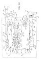
- an air conditioning and hot-water supply system includes: an air conditioning refrigerant circuit 5 that drives an air conditioning compressor 21 to selectively perform cooling operation and heating operation; a hot-water supply refrigerant circuit 6 that drives a hot-water supply compressor 41 to perform hot-water supply operation; an air conditioning cold/hot water circulation circuit 8 that exchanges heat with the air conditioning refrigerant circuit 5 to perform air conditioning of the inside of a house 60; a hot-water supply flow path 9 that exchanges heat with the hot-water supply refrigerant circuit 6 to perform hot-water supply; and a control device 1a that performs control of operation.
- the air conditioning and hot-water supply system is a system in which the air conditioning refrigerant circuit 5 and the hot-water supply refrigerant circuit 6 are thermally connected to each other through an intermediate heat exchanger 23 to form a dual refrigerating cycle of an air conditioning cycle and a hot-water supply cycle.
- the air conditioning and hot-water supply system has a unit configuration including a heat pump unit 1 disposed outside and an indoor unit 2 disposed inside.
- the air conditioning refrigerant circuit 5, the hot-water supply refrigerant circuit 6, the air conditioning cold/hot water circulation circuit 8, the hot-water supply flow path 9 and the control device 1a are incorporated in the heat pump unit 1.
- an indoor heat exchanger 61 that exchanges heat with air in the house 60 is incorporated in the indoor unit 2.
- the air conditioning refrigerant circuit 5 is a circuit through which an air conditioning refrigerant circulates to form a refrigerating cycle (air conditioning cycle), and has a configuration in which an air conditioning heat source side heat exchanger 24 that exchanges heat with outside air sent from an air conditioning outdoor fan 25 is connected to an air conditioning refrigerant main circuit 5a.
- the air conditioning refrigerant main circuit 5a is formed to be circular by connecting, with refrigerant piping, the air conditioning compressor 21 that compresses the air conditioning refrigerant, a four-way valve (air conditioning flow path switching valve) 22 that switches a flow path of the air conditioning refrigerant, the intermediate heat exchanger 23 that exchanges heat with a hot-water supply refrigerant circulating through the hot-water supply refrigerant circuit 6, an air conditioning refrigerant tank 26, an air conditioning expanding valve 27 that decompresses the air conditioning refrigerant, and an air conditioning use side heat exchanger 28 that exchanges heat with the air conditioning cold/hot water circulation circuit 8.
- heat exchange with the air conditioning cold/hot water circulation circuit 8 is performed, however, direct heat exchange with air in the house 60, not via the air conditioning cold/hot water circulation circuit 8, may be performed.
- the air conditioning heat source side heat exchanger 24 is connected between the four-way valve 22 and the air conditioning expanding valve 27 of the air conditioning refrigerant main circuit 5a in parallel with the intermediate heat exchanger 23.
- a first expanding valve (first air conditioning refrigerant flow control valve) 35c and a second expanding valve (second air conditioning refrigerant flow control valve) 35d that each control a flow rate of the air conditioning refrigerant are incorporated in an inlet and an outlet of the air conditioning heat source side heat exchanger 24.
- the air conditioning heat source side heat exchanger 24, the air conditioning outdoor fan 25, the first expanding valve 35c, and the second expanding valve 35d correspond to an air conditioning heat source side heat exchanger unit of the present invention.
- a refrigerant suited for a use condition is used from among R410a, R134a, HFO1234yf, HFO1234ze and CO2 as the air conditioning refrigerant that circulates through the air conditioning refrigerant circuit 5.
- the air conditioning compressor 21 is a variable displacement compressor whose capacity can be controlled.
- a piston type, rotary type, scroll type, screw type or centrifugal type can be adopted as such a compressor.
- the air conditioning compressor 21 is a scroll type compressor whose capacity can be controlled by inverter control, and whose rotational speed can be varied from a low speed to a high speed.
- the air conditioning use side heat exchanger 28 is, although not illustrated, configured such that an air conditioning refrigerant heat transfer tube through which the air conditioning refrigerant flows and an air conditioning cold/hot water heat transfer tube through which water (heat transfer medium on an air conditioning use side) flows contact thermally.
- the air conditioning refrigerant tank 26 has a function as a buffer that controls an amount of the air conditioning refrigerant that changes due to switching of a flow path of the air conditioning refrigerant circuit 5.
- the air conditioning expanding valve 27 can decompress the air conditioning refrigerant to a predetermined pressure by adjusting opening thereof.
- the air conditioning cold/hot water circulation circuit 8 is a circuit through which water flows as a heat transfer medium on an air conditioning use side for exchanging heat with the air conditioning refrigerant circuit 5, and is formed to be circular by connecting a four-way valve 53, an air conditioning cold/hot water circulation pump 52 and the indoor heat exchanger 61 installed in the house 60 with air conditioning cold/hot water piping 55a, connecting the indoor heat exchanger 61 and the four-way valve 22 with air conditioning cold/hot water piping 55b, and connecting the four-way valve 53 and the air conditioning use side heat exchanger 28 with air conditioning cold/hot water piping 55c.
- Water flowing in this air conditioning cold/hot water circulation circuit 8 (cold water or hot water) exchanges heat with air in the house 60 via the indoor heat exchanger 61 to cool or heat inside the house 60.
- brine such as ethylene glycol may be used instead of water. It is needless to say that use of brine allows application in a cold climate region.
- the hot-water supply refrigerant circuit 6 is a circuit through which a hot-water supply refrigerant circulates to form a refrigerating cycle (hot-water supply cycle), and has a configuration in which a hot-water supply heat source side heat exchanger 44 that exchanges heat with outside air sent from a hot-water supply outdoor fan 45 is connected to a hot-water supply refrigerant main circuit 6a.
- the hot-water supply refrigerant main circuit 6a is formed to be circular by connecting, with refrigerant piping, the hot-water supply compressor 41 that compresses the hot-water supply refrigerant, a hot-water supply use side heat exchanger 42 that exchanges heat with the hot-water supply flow path 9, a hot-water supply refrigerant tank 46 having a function as a buffer that controls an amount of the hot-water supply refrigerant, a hot-water supply expanding valve 43 that decompresses the hot-water supply refrigerant, and the intermediate heat exchanger 23 that exchanges heat with the air conditioning refrigerant circulating through the air conditioning refrigerant circuit 5.
- the hot-water supply heat source side heat exchanger 44 is connected between the hot-water supply compressor 41 and the hot-water supply expanding valve 43 of the hot-water supply refrigerant main circuit 6a in parallel with the intermediate heat exchanger 23.
- a third expanding valve (first hot-water supply refrigerant flow control valve) 49a and a fourth expanding valve (second hot-water supply refrigerant flow control valve) 49c that each control a flow rate of the hot-water supply refrigerant are incorporated in an inlet and an outlet of the hot-water supply heat source side heat exchanger 44.
- the hot-water supply heat source side heat exchanger 44, the hot-water supply outdoor fan 45, the third expanding valve 49a, and the fourth expanding valve 49c correspond to a hot-water supply heat source side heat exchanger unit of the present invention.
- a refrigerant suited for a use condition is used from among R410a, R134a, HFO1234yf HFO1234ze and CO2 as the hot-water supply refrigerant that circulates through the hot-water supply refrigerant circuit 6.
- Capacity of the hot-water supply compressor 41 can be controlled by inverter control in the same manner as the air conditioning compressor 21, and a rotational speed thereof can be varied from a low speed to a high speed.
- the hot-water supply use side heat exchanger 42 is, although not illustrated, configured such that a hot-water supply water heat transfer tube through which water to be supplied to the hot-water supply flow path 9 flows and a hot-water supply refrigerant heat transfer tube through which the hot-water supply refrigerant flows contact thermally.
- the hot-water supply expanding valve 43 can decompress the hot-water supply refrigerant to a predetermined pressure by adjusting opening thereof.
- a plate heat exchanger is used as the intermediate heat exchanger 23. Also, two-way valves 35a, 35b are provided at an inlet and an outlet of the intermediate heat exchanger 23 of the air conditioning refrigerant circuit 5, and two-way valves 49b, 49d are provided at an inlet and an outlet of the intermediate heat exchanger 23 of the hot-water supply refrigerant circuit 6.
- the hot-water supply flow path 9 is a flow path through which water as a heat transfer medium on a hot-water supply use side flows, and is formed by connecting an inlet of the hot-water supply use side heat exchanger 42 and a water supply port 78 with hot-water supply piping 72, and connecting an outlet of the hot-water supply use side heat exchanger 42 and a hot-water supply port 79 with hot-water supply piping 73.
- a hot water storage tank 70 is attached to the hot-water supply piping 73. The water supplied from the water supply port 78 undergoes heat exchange with the hot-water supply use side heat exchanger 42 and becomes hot water, and then the hot water is stored in the hot water storage tank 70.
- the hot water stored in the hot water storage tank 70 is supplied from the hot-water supply port 79 to a hot-water supply load side (bathtub, lavatory, kitchen and the like).
- drain piping 71a and a drain valve 71b are provided at a bottom of the hot water storage tank 70.
- the drain valve 71b is normally closed.
- the drain valve 71b is opened to discharge the hot water stored in the hot water storage tank 70 to the outside through the drain piping 71a.
- a flow sensor that detects a flow rate of water is incorporated in the hot-water supply flow path 9.
- This air conditioning and hot-water supply system includes plural temperature sensors TH1 to TH20. Specifically, for measuring the temperature of water flowing through the hot-water supply flow path 9, the temperature sensor TH2 is provided at an inlet of the hot-water supply use side heat exchanger 42, and the temperature sensor TH1 is provided at the water supply port 78. Also, for measuring the temperature of cold/hot water flowing through the air conditioning cold/hot water circulation circuit 8, the temperature sensor TH4 is provided at an inlet in heating operation of the air conditioning use side heat exchanger 28, the temperature sensor TH3 is provided at an outlet in heating operation of the air conditioning use side heat exchanger 28, and the temperature sensor TH5 is provided at an outlet of the indoor heat exchanger 61.
- the temperature sensor TH6 is provided at a suction port 41a of the hot-water supply compressor 41, the temperature sensor TH7 is provided at a discharge port 41b of the hot-water supply compressor 41, the temperature sensor TH8 is provided at an outlet of the hot-water supply expanding valve 43, the temperature sensor TH9 is provided at an outlet of the hot-water supply heat source side heat exchanger 44, and the temperature sensor TH10 is provided at an outlet of the intermediate heat exchanger 23.
- the temperature sensor TH11 is provided at a suction port 21a of the air conditioning compressor 21
- the temperature sensor TH12 is provided at a discharge port 21b of the air conditioning compressor 21
- the temperature sensors TH13 and TH14 are provided at an inlet and an outlet of the intermediate heat exchanger 23
- the temperature sensors TH15 and TH16 are provided at an inlet and an outlet of the air conditioning heat source side heat exchanger 24
- the temperature sensor TH17 is provided at an outlet in cooling operation of the air conditioning expanding valve 43
- the temperature sensor TH18 is provided at an outlet in cooling operation of the air conditioning use side heat exchanger 28.
- the air conditioning and hot-water supply system is provided with the temperature sensor TH19 for measuring outside air temperature, the temperature sensor TH20 for measuring the temperature of air in the house 60, and the temperature sensor TH21 for measuring the temperature of hot water stored in the hot water storage tank 70.
- a rotational speed detecting sensor RA for detecting rotational speed is provided to the air conditioning compressor 21.
- a rotational speed detecting sensor RH is similarly provided to the hot-water supply compressor 41.
- a valve opening detecting sensor PA that detects opening of a valve is provided to the air conditioning expanding valve 27, and a valve opening detecting sensor PH that detects opening of a valve is provided to the hot-water supply expanding valve 43.
- the control device 1a receives inputs such as command signals from an unillustrated remote controller and detection signals from the temperature sensors TH1 to TH21, the rotational speed detecting sensors RA, RH and the valve opening detecting sensors PA, PH, and based on these input signals, performs: driving/stopping of the air conditioning compressor 21 and the hot-water supply compressor 41; switching of the four-way valves 22, 53; adjustment of opening of the air conditioning expanding valve 27 and the hot-water supply expanding valve 43; adjustment of opening of the expanding valves 35c, 35d, 49a, 49c; driving/stopping of the air conditioning cold/hot water circulation pump 52; opening and closing of the two-way valves 35a, 35b, 49a, 49d, 54a, 54b; and other control necessary for operation of the air conditioning and hot-water supply system.
- inputs such as command signals from an unillustrated remote controller and detection signals from the temperature sensors TH1 to TH21, the rotational speed detecting sensors RA, RH and the valve opening detecting sensors PA,
- the air conditioning and hot-water supply system according to the first embodiment includes eight operation modes: "cooling/hot-water supply individual operation mode”, “heating/hot-water supply individual operation mode”, “scheduled operation mode”, “high heating operation mode”, “flash boiling operation mode”, “rapid cooling operation mode”, “zero exhaust hot-air operation mode”, and "energy-saving operation mode”.
- the "cooling/hot-water supply individual operation mode” is an operation mode in which cooling operation by the air conditioning refrigerant circuit 5 and hot-water supply operation by the hot-water supply refrigerant circuit 6 are individually performed.
- this operation mode as shown in Fig. 2 , during the hot-water supply cycle, the hot-water supply compressor 41 is operated; the hot-water supply use side heat exchanger 42 is used as a condenser; the hot-water supply heat source side heat exchanger 44 is used as an evaporator; and the intermediate heat exchanger 23 is not used.
- the air conditioning compressor 21 is operated; the air conditioning use side heat exchanger 28 is used as an evaporator; the air conditioning heat source side heat exchanger 24 is used as a condenser; and the intermediate heat exchanger 23 is not used.
- the "heating/hot-water supply individual operation mode” is an operation mode in which heating operation by the air conditioning refrigerant circuit 5 and hot-water supply operation by the hot-water supply refrigerant circuit 6 are individually performed.
- this operation mode as shown in Fig. 2 , during the hot-water supply cycle, the hot-water supply compressor 41 is operated; the hot-water supply use side heat exchanger 42 is used as a condenser; the hot-water supply heat source side heat exchanger 44 is used as an evaporator; and the intermediate heat exchanger 23 is not used.
- the air conditioning compressor 21 is operated; the air conditioning use side heat exchanger 28 is used as a condenser; the air conditioning heat source side heat exchanger 24 is used as an evaporator; and the intermediate heat exchanger 23 is not used.
- the “scheduled operation mode” is an operation mode in which cooling operation by the air conditioning refrigerant circuit 5 and hot-water supply operation by the hot-water supply refrigerant circuit 6 are performed while exchanging heat between the air conditioning refrigerant flowing through the air conditioning refrigerant circuit 5 and the hot-water supply refrigerant flowing through the hot-water supply refrigerant circuit 6 via the intermediate heat exchanger 23.
- this scheduled operation mode three operation modes of control-1 to control-3 are set according to the relation between a hot-water supply heat absorption amount required by the hot-water supply refrigerant circuit 6 and an air conditioning heat radiation amount required by the air conditioning refrigerant circuit 5.
- control-1 mode is performed when the hot-water supply heat absorption amount and the air conditioning heat radiation amount are assumed to be equal from the fact that the difference therebetween falls within a predetermined range, that is, when the air conditioning and hot-water supply system is in a third load condition.
- the hot-water supply compressor 41 is operated; the hot-water supply use side heat exchanger 42 is used as a condenser; the hot-water supply heat source side heat exchanger 44 is not used; and the intermediate heat exchanger 23 is used as an evaporator.
- the air conditioning compressor 21 is operated; the air conditioning use side heat exchanger 28 is used as an evaporator; the air conditioning heat source side heat exchanger 24 is not used; and the intermediate heat exchanger 23 is used as a condenser.
- the operation is performed by using only the intermediate heat exchanger 23 without using the hot-water supply heat source side heat exchanger 44 and the air conditioning heat source side heat exchanger 24.
- control-2 mode is performed when the air conditioning heat radiation amount is larger than the hot-water supply heat absorption amount, that is, when the air conditioning and hot-water supply system is in a first load condition.
- the hot-water supply compressor 41 is operated; the hot-water supply use side heat exchanger 42 is used as a condenser; the hot-water supply heat source side heat exchanger 44 is not used; and the intermediate heat exchanger 23 is used as an evaporator.
- the air conditioning compressor 21 is operated; the air conditioning use side heat exchanger 28 is used as an evaporator; the air conditioning heat source side heat exchanger 24 is used as a condenser; and the intermediate heat exchanger 23 is used as a condenser.
- the air conditioning heat radiation amount is larger than the hot-water supply heat absorption amount, a heat-amount balance cannot be achieved simply by radiating exhaust heat of the air conditioning cycle to the hot-water supply cycle via the intermediate heat exchanger 23. Therefore, cooling operation and hot-water supply operation are performed while radiating a differential amount of heat (surplus heat) equivalent to the difference between the air conditioning heat radiation amount and the hot-water supply heat absorption amount from the air conditioning heat source side heat exchanger 24 to outside air.
- control-3 mode is performed when the hot-water supply heat absorption amount is larger than the air conditioning heat radiation amount, that is, when the air conditioning and hot-water supply system is in a second load condition.
- the hot-water supply compressor 41 is operated; the hot-water supply use side heat exchanger 42 is used as a condenser; the hot-water supply heat source side heat exchanger 44 is used as an evaporator; and the intermediate heat exchanger 23 is used as an evaporator.
- the air conditioning compressor 21 is operated; the air conditioning use side heat exchanger 28 is used as an evaporator; the air conditioning heat source side heat exchanger 24 is not used; and the intermediate heat exchanger 23 is used as a condenser.
- the hot-water supply heat absorption amount is larger than the air conditioning heat radiation amount, a heat-amount balance cannot be achieved simply by radiating exhaust heat of the air conditioning cycle to the hot-water supply cycle via the intermediate heat exchanger 23.
- cooling operation and hot-water supply operation are performed while absorbing a differential amount of heat (heat shortage) equivalent to the difference between the air conditioning heat radiation amount and the hot-water supply heat absorption amount from outside air via the hot-water supply heat source side heat exchanger 44.
- the "high heating operation mode” is an operation mode in which heating operation by the air conditioning refrigerant circuit 5, with the intermediate heat exchanger 23 secondarily used, and hot-water supply operation by the hot-water supply refrigerant circuit 6 are performed.
- this operation mode as shown in Fig. 3 , during the hot-water supply cycle, the hot-water supply compressor 41 is operated; the hot-water supply use side heat exchanger 42 is used as a condenser; the hot-water supply heat source side heat exchanger 44 is used as an evaporator; and the intermediate heat exchanger 23 is not used.
- the air conditioning compressor 21 is operated; the air conditioning use side heat exchanger 28 is used as a condenser; the air conditioning heat source side heat exchanger 24 is used as an evaporator; and the intermediate heat exchanger 23 is used as a secondary evaporator.
- the evaporation temperature of the air conditioning cycle can be increased not only by using the air conditioning heat source side heat exchanger 24 as an evaporator but also by using the intermediate heat exchanger 23 as an evaporator as much as possible through the use of a heat-transfer surface of the plate of the intermediate heat exchanger 23. Therefore, this operation mode is suitable especially for the case where a room does not get warm enough in winter.
- the “flash boiling operation mode” is an operation mode in which cooling operation by the air conditioning refrigerant circuit 5 and hot-water supply operation by the hot-water supply refrigerant circuit 6 are performed while exchanging heat between the air conditioning refrigerant flowing through the air conditioning refrigerant circuit 5 and the hot-water supply refrigerant flowing through the hot-water supply refrigerant circuit 6 via the intermediate heat exchanger 23.
- this operation mode as shown in Fig. 3 , during the hot-water supply cycle, the hot-water supply compressor 41 is operated; the hot-water supply use side heat exchanger 42 is used as a condenser; the hot-water supply heat source side heat exchanger 44 is used as an evaporator; and the intermediate heat exchanger 23 is used as an evaporator.
- the air conditioning compressor 21 is operated; the air conditioning use side heat exchanger 28 is used as an evaporator; the air conditioning heat source side heat exchanger 24 is not used; and the intermediate heat exchanger 23 is used as a condenser.
- This flash boiling operation mode is suitable for the case where a hot-water supply load increases temporarily, as for example when lots of hot water is temporarily needed.
- the "rapid cooling operation mode” is an operation mode in which cooling operation by the air conditioning refrigerant circuit 5 and hot-water supply operation by the hot-water supply refrigerant circuit 6 are performed while exchanging heat between the air conditioning refrigerant flowing through the air conditioning refrigerant circuit 5 and the hot-water supply refrigerant flowing through the hot-water supply refrigerant circuit 6 via the intermediate heat exchanger 23.
- this operation mode as shown in Fig. 3 , during the hot-water supply cycle, the hot-water supply compressor 41 is operated; the hot-water supply use side heat exchanger 42 is used as a condenser; the hot-water supply heat source side heat exchanger 44 is not used; and the intermediate heat exchanger 23 is used as an evaporator.
- the air conditioning compressor 21 is operated at a predetermined operating rotational speed (maximum rotational speed); the air conditioning use side heat exchanger 28 is used as an evaporator; the air conditioning heat source side heat exchanger 24 is used as a condenser; and the intermediate heat exchanger 23 is used as a condenser.
- This rapid cooling operation mode is suitable for the case where there is a need to quickly cool the inside of a room in summer.
- the “zero exhaust hot-air operation mode” is an operation mode in which cooling operation by the air conditioning refrigerant circuit 5 and hot-water supply operation by the hot-water supply refrigerant circuit 6 are performed while exchanging heat between the air conditioning refrigerant flowing through the air conditioning refrigerant circuit 5 and the hot-water supply refrigerant flowing through the hot-water supply refrigerant circuit 6 via the intermediate heat exchanger 23.
- this operation mode as shown in Fig. 3 , during the hot-water supply cycle, the hot-water supply compressor 41 is operated; the hot-water supply use side heat exchanger 42 is used as a condenser; the hot-water supply heat source side heat exchanger 44 is not used; and the intermediate heat exchanger 23 is used as an evaporator.
- the air conditioning compressor 21 is operated (and then stopped); the air conditioning use side heat exchanger 28 is used as an evaporator; the air conditioning heat source side heat exchanger 24 is not used; and the intermediate heat exchanger 23 is used as a condenser.
- This zero exhaust hot-air operation mode is suitable for the case where there is a need to prevent hot air from being released from the air conditioning heat source side heat exchanger 24.
- the “energy-saving operation mode” is an operation mode in which cooling operation by the air conditioning refrigerant circuit 5 and hot-water supply operation by the hot-water supply refrigerant circuit 6 are performed while exchanging heat between the air conditioning refrigerant flowing through the air conditioning refrigerant circuit 5 and the hot-water supply refrigerant flowing through the hot-water supply refrigerant circuit 6 via the intermediate heat exchanger 23.
- this operation mode as shown in Fig. 3 , during the hot-water supply cycle, the hot-water supply compressor 41 is operated; the hot-water supply use side heat exchanger 42 is used as a condenser; the hot-water supply heat source side heat exchanger 44 is not used; and the intermediate heat exchanger 23 is used as an evaporator.
- the air conditioning compressor 21 is operated (and then stopped); the air conditioning use side heat exchanger 28 is used as an evaporator; the air conditioning heat source side heat exchanger 24 is not used; and the intermediate heat exchanger 23 is used as a condenser.
- This energy-saving operation mode is suitable for the case where there is a need to perform hot-water supply operation and cooling operation while keeping electricity costs low anyway.
- Figs. 4 , 5 , 9 to 12 white thick arrows given to the heat exchangers show flows of heat, and arrows given to the circuits 5, 6, 8, 9 show directions of the refrigerant or fluid flowing through each circuit.
- a white two-way valve shows that it is in an open state
- a black two-way valve shows that it is in a closed state.
- the expanding valves 35c, 35d, 49a, 49c a white expanding valve shows that it is in an open state
- a black expanding valve shows that it is in a closed state.
- arc-shaped solid lines depicted in the four-way valves 22, 53 show flow paths of fluid flowing through the four-way valves.
- a white fan shows that it is in operation, and a black fan shows that it is out of operation.
- a heat exchanger shown with a dotted line shows a heat exchanger unused in each operation mode, that is, a heat exchanger with no refrigerant flowing.
- a high-temperature and high-pressure gas refrigerant discharged from the discharge port 21b of the air conditioning compressor 21 passes through the four-way valve 22 and flows into the air conditioning heat source side heat exchanger 24.
- the high-temperature and high-pressure gas refrigerant flowing in the air conditioning heat source side heat exchanger 24 radiates heat to outside air sent from the air conditioning outdoor fan 25 to be condensed and liquefied.
- This high-pressure liquid refrigerant flows through the air conditioning refrigerant tank 26, and then is decompressed by the air conditioning expanding valve 27 adjusted to a predetermined opening and expands to become a low-temperature and low-pressure, vapor-liquid two-phase refrigerant and flow into the air conditioning use side heat exchanger 28.
- the vapor-liquid two-phase refrigerant flowing in the air conditioning use side heat exchanger 28 absorbs heat from high-temperature cold water flowing in the air conditioning cold/hot water circulation circuit 8 to evaporate and become a low-pressure gas refrigerant.
- This low-pressure gas refrigerant passes through the four-way valve 22, flows into the suction port 21a of the air conditioning compressor 21, and is compressed again by the air conditioning compressor 21 to become a high-temperature and high-pressure gas refrigerant.
- the cold water having radiated heat to the air conditioning refrigerant flowing through the air conditioning use side heat exchanger 28 is caused to pass through the air conditioning cold/hot water piping 55a and flow into the indoor heat exchanger 61 by driving the air conditioning cold/hot water circulation pump 52.
- the indoor heat exchanger 61 cold water in the air conditioning cold/hot water circulation circuit 8 and high-temperature air in the house 60 exchange heat, and the air in the house 60 is cooled. That is, the inside of the house 60 is cooled.
- the cold water flowing through the indoor heat exchanger 61 absorbs heat from the air in the house 60, and is raised in temperature.
- This cold water raised in temperature flows through the air conditioning cold/hot water piping 55b, 55c due to the air conditioning cold/hot water circulation pump 52, and while flowing through the air conditioning use side heat exchanger 28 again, exchanges heat with the air conditioning refrigerant flowing through the air conditioning refrigerant circuit 5 to be cooled.
- the gas refrigerant compressed to high temperature and pressure by the hot-water supply compressor 41 flows into the hot-water supply use side heat exchanger 42.
- the high-temperature and high-pressure gas refrigerant flowing in the hot-water supply use side heat exchanger 42 radiates heat to water flowing in the hot-water supply flow path 9 to be condensed and liquefied.
- the liquefied high-pressure refrigerant flows through the hot-water supply refrigerant tank 46, and then is decompressed by the hot-water supply expanding valve 43 adjusted to a predetermined opening, and expands to become a low-temperature and low-pressure, vapor-liquid two-phase refrigerant.
- This vapor-liquid two-phase refrigerant absorbs heat from outside air sent from the hot-water supply outdoor fan 45 and evaporates while flowing through the hot-water supply heat source side heat exchanger 44 to become a low-pressure gas refrigerant.
- This low-pressure gas refrigerant flows into the suction port 41a of the hot-water supply compressor 41, and is compressed again by the hot-water supply compressor 41 to become a high-temperature and high-pressure gas refrigerant.
- the water having flowed into the water supply port 78 flows in the hot-water supply piping 72 to be guided to the hot-water supply use side heat exchanger 42.
- the water having flowed into the hot-water supply use side heat exchanger 42 absorbs heat from the hot-water supply refrigerant flowing though the hot-water supply refrigerant circuit 6 in the hot-water supply use side heat exchanger 42, and turns into high-temperature hot water.
- This hot water flows in the hot-water supply piping 73 and is stored in the hot water storage tank 70.
- the stored hot water flows out of the hot-water supply port 79 to be guided to the hot-water supply load side upon request of a user.
- a high-temperature and high-pressure gas refrigerant discharged from the discharge port 21b of the air conditioning compressor 21 passes through the four-way valve 22, and flows into the air conditioning use side heat exchanger 28.
- the high-temperature and high-pressure gas refrigerant flowing in the air conditioning use side heat exchanger 28 radiates heat to hot water flowing in the air conditioning cold/hot water circuit 8 to be condensed and liquefied.
- This high-pressure liquid refrigerant is decompressed by the air conditioning expanding valve 27 adjusted to a predetermined opening, expands to become a low-temperature and low-pressure, vapor-liquid two-phase refrigerant, passes through the air conditioning refrigerant tank 26, and flows into the air conditioning heat source side heat exchanger 24.
- the vapor-liquid two-phase refrigerant flowing in the air conditioning heat source side heat exchanger 24 absorbs heat from outside air sent from the air conditioning outdoor fan 25 to evaporate and become a low-pressure gas refrigerant.
- This low-pressure gas refrigerant passes through the four-way valve 22, flows into the suction port 21a of the air conditioning compressor 21, and is compressed again by the air conditioning compressor 21 to become a high-temperature and high-pressure gas refrigerant.
- the hot water raised in temperature by absorbing heat from the air conditioning refrigerant flowing through the air conditioning use side heat exchanger 28 is caused to pass through the air conditioning cold/hot water piping 55a and flow into the indoor heat exchanger 61 by driving the air conditioning cold/hot water circulation pump 52.
- the indoor heat exchanger 61 hot water in the air conditioning cold/hot water circulation circuit 8 and low-temperature air in the house 60 exchange heat, and the air in the house 60 is heated. That is, the inside of the house 60 is heated. At this time, the hot water flowing through the indoor heat exchanger 61 radiates heat to the air in the house 60 to be cooled.
- This cooled hot water flows through the air conditioning cold/hot water piping 55b, 55c due to the air conditioning cold/hot water circulation pump 52, and while flowing through the air conditioning use side heat exchanger 28 again, exchanges heat with the air conditioning refrigerant flowing through the air conditioning refrigerant circuit 5, and consequently the temperature thereof is raised.
- flows of a hot-water supply refrigerant in the hot-water supply refrigerant circuit 6 and water in the hot-water supply flow path 9 are the same as those of the "cooling/hot-water supply individual operation mode", and therefore the explanation thereof will not be repeated here. It should be also noted that, in this "heating/hot-water supply individual operation mode", the flow path through which the refrigerant flows to the intermediate heat exchanger 23 is blocked by the two-way valves 35a, 35b, 49b, 49d, so that heat exchange between the air conditioning refrigerant and the hot-water supply refrigerant is not performed.
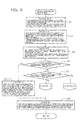
- the control device 1a calculates and compares a heat radiation amount required by the air conditioning refrigerant circuit 5 and a heat absorption amount required by the hot-water supply refrigerant circuit 6, and determines one of the "control-1 mode", the "control-2 mode", and the "control-3 mode” on the basis of the comparison result, and controls operation of the air conditioning and hot-water supply system in accordance with the determination. Therefore, firstly, a procedure of control process executed by the control device 1a will be explained with reference to Figs. 6 to 8 .
- the control device 1a executes a process of receiving various data. Specifically, the control device 1a receives data of target hot water temperature (boiling temperature), a target hot water amount (flow rate), and tap water temperature in the hot-water supply cycle, and also receives data of target temperature (preset temperature), target air volume, and indoor temperature in the air conditioning cycle.
- target hot water temperature and target hot water amount of the hot-water supply cycle are data to be input to the control device 1a by remote control settings
- the tap water temperature is data to be input from the temperature sensor TH1.
- the target temperature and target air volume of the air conditioning cycle are data to be input to the control device 1a by remote control settings
- the indoor temperature is data to be input from the temperature sensor TH20.
- control device 1a proceeds to Step S2, and executes a process of calculation on the basis of the various data received at Step S1. Specifically, the control device 1a calculates target capacity (Qh), a target rotational speed of the hot-water supply compressor 41, target discharge temperature (Td) of the hot-water supply compressor 41, and an input (Whcomp) of the hot-water supply compressor 41 in the hot-water supply cycle, and also calculates target capacity (Qc), a target rotational speed of the air conditioning compressor 21, target evaporation temperature (Te) of the air conditioning refrigerant, and an input (Wccomp) of the air conditioning compressor 21 in the air conditioning cycle.
- Step S3 calculates a hot-water supply heat absorption amount from the difference between the target capacity (Qh) and the compressor input (Whcomp) of the hot-water supply cycle, and also calculates an air conditioning heat radiation amount from the sum of the target capacity (Qc) and the compressor input (Wccomp) of the air conditioning cycle.
- Step S4 determines whether or not the hot-water supply heat absorption amount and air conditioning heat radiation amount calculated at Step S3 are equal, that is, whether or not the current load is in the third load condition. It should be noted that, at Step S4, if the difference between the hot-water supply heat absorption amount and the air conditioning heat radiation amount falls within a predetermined value range, the two amounts are determined to be equal. If Yes at Step S4, the control device 1a proceeds to Step S5, and executes process of the "control-1 mode".
- control device 1a opens the two-way valves 35a, 35b, 49b, 49d located at the inlet and outlet of the intermediate heat exchanger 23; closes the third expanding valve 49a and the fourth expanding valve 49c located at the inlet and outlet of the hot-water supply heat source side heat exchanger 44; and closes the first expanding valve 35c and the second expanding valve 35d located at the inlet and outlet of the air conditioning heat source side heat exchanger 24. That is, since the hot-water supply heat absorption amount and air conditioning heat radiation amount are equal, the control device 1a brings about a state that allows cooling operation and hot-water supply operation using only the intermediate heat exchanger 23.
- Step S6 controls operation of the hot-water supply cycle and the air conditioning cycle according to the calculation results of Step S2.
- the control device 1a in the hot-water supply cycle, controls the hot-water supply compressor 41 so that it is operated at the target rotational speed; stops the hot-water supply outdoor fan 45; and controls opening of the hot-water supply expanding valve 43 so that the target discharge temperature (Td) is reached.
- the control device 1a in the air conditioning cycle, controls the air conditioning compressor 21 so that it is operated at a predetermined rotational speed; stops the air conditioning outdoor fan 25; and controls opening of the air conditioning expanding valve 27 so that the target evaporation temperature (Te) is reached.
- a return is executed, and the scheduled operation process exits.
- Step S7 determines whether or not the hot-water supply heat absorption amount is smaller than the air conditioning heat radiation amount. If the hot-water supply heat absorption amount is determined to be smaller than the air conditioning heat radiation amount, that is, when the current load is in the first load condition, the control device 1a executes process of the "control-2 mode". If the hot-water supply heat absorption amount is determined to be larger than the air conditioning heat radiation amount, that is, when the current load is in the second load condition, the control device 1a executes process of the "control-3 mode".
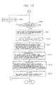
- Step S8 the control device 1a opens the two-way valves 35a, 35b, 49b, 49d located at the inlet and outlet of the intermediate heat exchanger 23; closes the third expanding valve 49a and the fourth expanding valve 49c located at the inlet and outlet of the hot-water supply heat source side heat exchanger 44; and opens the first expanding valve 35c and the second expanding valve 35d located at the inlet and outlet of the air conditioning heat source side heat exchanger 24.
- the control device 1a brings about a state that allows cooling operation and hot-water supply operation while radiating the differential amount of heat equivalent to the difference between the air conditioning heat radiation amount and the hot-water supply heat absorption amount from the air conditioning heat source side heat exchanger 24 to outside air.
- Step S9 the control device 1a proceeds to Step S9, and executes a process of receiving various data. Specifically, the control device 1a receives data of the hot-water supply heat absorption amount and the air conditioning heat radiation amount calculated at Step S3 and data of outside air temperature input from the temperature sensor TH19. And then the control device 1a proceeds to Step S10, and calculates target evaporation temperature (Te) of the hot-water supply refrigerant in the hot-water supply cycle and target condensation temperature (Tc) of the air conditioning refrigerant in the air conditioning cycle on the basis of the various data received at Step S9.
- Te target evaporation temperature
- Tc target condensation temperature
- Step S11 controls operation of the hot-water supply cycle and the air conditioning cycle according to the calculation results of Step S9.
- the control device 1a in the hot-water supply cycle, controls the hot-water supply compressor 41 so that it is operated at the target rotational speed; stops the hot-water supply outdoor fan 45; and controls opening of the hot-water supply expanding valve 43 so that the target evaporation temperature (Te) is reached.
- the control device 1a in the air conditioning cycle, controls the air conditioning compressor 21 so that it is operated at the target rotational speed; controls rotational speed of the air conditioning outdoor fan 25 so that the target condensation temperature (Tc) is reached; and controls opening of the air conditioning expanding valve 27 so that the target condensation temperature (Tc) is reached.
- Step S12 determines whether or not the target evaporation temperature (Te) of the hot-water supply cycle is reached. If Yes at Step S12, the control device 1a proceeds to Step S13, and determines whether or not the target condensation temperature (Tc) of the air conditioning cycle is reached. If Yes at Step S13, the control device 1a proceeds to Step S15, and confirms whether or not the hot-water supply cycle is operated at the target hot-water supply capacity (Qh) and also whether or not the air conditioning cycle is operated at the target air conditioning capacity (Qc). And then if Yes at Step S15, a return is executed at next step, and the scheduled operation process exits. It should be noted that, if No at Step S15, the control device 1a returns to Step S11.
- the control device 1a returns to Step S11, and adjusts opening of the hot-water supply expanding valve 43 until the target evaporation temperature (Te) of the hot-water supply cycle is reached.
- the control device 1a firstly controls the hot-water supply cycle, which is smaller in the amount of heat, so that the target evaporation temperature (Te) is reached.
- the control device 1a adjusts (slightly closes) opening of the first expanding valve 35c and the second expanding valve 35d at Step S14.
- control device 1a returns to Step S11, and adjusts opening of the first expanding valve 35c and the second expanding valve 35d until the target condensation temperature (Tc) of the air conditioning cycle is reached.
- the control device 1a controls operation of the air conditioning cycle after the hot-water supply cycle has reached the target evaporation temperature (Te).
- the rotational speed of the air conditioning outdoor fan 25 is adjusted (Step S11), and then if the air conditioning cycle does not reach the target condensation temperature (Tc) (No at Step S14), the opening of the first expanding valve 35c and the second expanding valve 35d located at the inlet and outlet of the air conditioning heat source side heat exchanger 24 is secondarily adjusted.
- control device 1a adjusts opening of the first expanding valve 35c and the second expanding valve 35d to make up the difference therebetween, and performs control so that the balance between the amounts of heat to be exchanged is maintained.
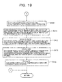
- the control device 1a opens the two-way valves 35a, 35b, 49b, 49d located at the inlet and outlet of the intermediate heat exchanger 23; opens the third expanding valve 49a and the fourth expanding valve 49c located at the inlet and outlet of the hot-water supply heat source side heat exchanger 44; and closes the first expanding valve 35c and the second expanding valve 35d located at the inlet and outlet of the air conditioning heat source side heat exchanger 24.
- the control device 1a brings about a state that allows cooling operation and hot-water supply operation while absorbing the differential amount of heat equivalent to the difference between the hot-water supply heat absorption amount and the air conditioning heat radiation amount from outside air in the hot-water supply heat source side heat exchanger 44.
- Step S17 the control device 1a proceeds to Step S17, and executes a process of receiving various data. Specifically, the control device 1a receives data of the hot-water supply heat absorption amount and the air conditioning heat radiation amount calculated at Step S3 and data of outside air temperature input from the temperature sensor TH19. And then the control device 1a proceeds to Step S18, and calculates target evaporation temperature (Te) of the hot-water supply refrigerant in the hot-water supply cycle and target condensation temperature (Tc) of the air conditioning refrigerant in the air conditioning cycle on the basis of the various data received at Step S17.
- Te target evaporation temperature
- Tc target condensation temperature
- Step S19 controls operation of the hot-water supply cycle and the air conditioning cycle according to the calculation results of Step S18.
- the control device 1a in the hot-water supply cycle, controls the hot-water supply compressor 41 so that it is operated at the target rotational speed; controls rotational speed of the hot-water supply outdoor fan 45 so that the target evaporation temperature (Te) is reached; and controls opening of the hot-water supply expanding valve 43 so that the target evaporation temperature (Te) is reached.
- the control device 1a in the air conditioning cycle, controls the air conditioning compressor 21 so that it is operated at the target rotational speed; stops the air conditioning outdoor fan 25; and controls opening of the air conditioning expanding valve 27 so that the target condensation temperature (Tc) is reached.
- Step S20 determines whether or not the target condensation temperature (Tc) of the air conditioning cycle is reached. If Yes at Step S20, the control device 1a proceeds to Step S21, and determines whether or not the target evaporation temperature (Te) of the hot-water supply cycle is reached. If Yes at Step S21, the control device 1a proceeds to Step S23, and confirms whether or not the hot-water supply cycle is operated at the target hot-water supply capacity (Qh) and also whether or not the air conditioning cycle is operated at the target air conditioning capacity (Qc). And then if Yes at Step S23, a return is executed at next step, and the scheduled operation process exits. It should be noted that, if No at Step S23, the control device 1a returns to Step S19.
- the control device 1a returns to Step S19, and adjusts opening of the air conditioning expanding valve 27 until the target condensation temperature (Tc) of the air conditioning cycle is reached.
- the control device 1a firstly controls the air conditioning cycle, which is smaller in the amount of heat, so that the target condensation temperature (Tc) is reached. Also, if No at Step S21, the control device 1a adjusts (slightly closes) opening of the third expanding valve 49a and the fourth expanding valve 49c at Step S22.
- control device 1a returns to Step S19, and adjusts opening of the third expanding valve 49a and the fourth expanding valve 49c until the target evaporation temperature (Te) of the hot-water supply cycle is reached.
- the control device 1a controls operation of the hot-water supply cycle after the air conditioning cycle has reached the target condensation temperature (Tc).
- the rotational speed of the hot-water supply outdoor fan 45 is adjusted (Step S19), and then if the hot-water supply cycle does not reach the target evaporation temperature (Te) (No at Step S21), opening of the third expanding valve 49a and the fourth expanding valve 49c located at the inlet and outlet of the hot-water supply heat source side heat exchanger 44 is secondarily adjusted.
- control device 1a adjusts opening of the third expanding valve 49a and the fourth expanding valve 49c to make up the difference, and performs control so that the balance between the amounts of heat to be exchanged is maintained.
- control-1 mode will be explained using Fig. 9 .
- the first expanding valve 35c, the second expanding valve 35d, the third expanding valve 49a, and the fourth expanding valve 49c are closed, and the air conditioning outdoor fan 25 and the hot-water supply outdoor fan 45 are stopped.
- a high-temperature and high-pressure gas refrigerant discharged from the discharge port 21b of the air conditioning compressor 21 passes through the four-way valve 22, and flows into the intermediate heat exchanger 23.
- the high-temperature and high-pressure gas refrigerant flowing in the intermediate heat exchanger 23 radiates heat to a low-temperature hot-water supply refrigerant flowing through the intermediate heat exchanger 23 to be condensed and liquefied.
- This high-pressure liquid refrigerant flows through the air conditioning refrigerant tank 26, and then is decompressed by the air conditioning expanding valve 27 adjusted to a predetermined opening, expands to become a low-temperature and low-pressure, vapor-liquid two-phase refrigerant, and flows into the air conditioning use side heat exchanger 28.
- the vapor-liquid two-phase refrigerant flowing in the air conditioning use side heat exchanger 28 absorbs heat from high-temperature cold water flowing in the air conditioning cold/hot water circulation circuit 8 to evaporate and become a low-pressure gas refrigerant.
- This low-pressure gas refrigerant passes through the four-way valve 22, flows into the suction port 21a of the air conditioning compressor 21, and is compressed again by the air conditioning compressor 21 to become a high-temperature and high-pressure gas refrigerant.
- the cold water having radiated heat to the air conditioning refrigerant flowing through the air conditioning use side heat exchanger 28 is caused to pass through the air conditioning cold/hot water piping 55a and flow into the indoor heat exchanger 61 by driving the air conditioning cold/hot water circulation pump 52.
- the indoor heat exchanger 61 cold water in the air conditioning cold/hot water circulation circuit 8 and high-temperature air in the house 60 exchange heat, and the air in the house 60 is cooled. That is, the inside of the house 60 is cooled.
- the cold water flowing through the indoor heat exchanger 61 absorbs heat from the air in the house 60, and is raised in temperature.
- This cold water raised in temperature flows through the air conditioning cold/hot water piping 55b, 55c due to the air conditioning cold/hot water circulation pump 52, and while flowing through the air conditioning use side heat exchanger 28 again, exchanges heat with the air conditioning refrigerant flowing through the air conditioning refrigerant circuit 5 to be cooled.
- the gas refrigerant compressed to high temperature and pressure by the hot-water supply compressor 41 flows into the hot-water supply use side heat exchanger 42.
- the high-temperature and high-pressure gas refrigerant flowing in the hot-water supply use side heat exchanger 42 radiates heat to water flowing in the hot-water supply flow path 9 to be condensed and liquefied.
- the liquefied high-pressure refrigerant flows through the hot-water supply refrigerant tank 46, and then is decompressed by the hot-water supply expanding valve 43 adjusted to a predetermined opening, and expands to become a low-temperature and low-pressure, vapor-liquid two-phase refrigerant.
- This vapor-liquid two-phase refrigerant absorbs heat from the high-temperature air conditioning refrigerant flowing through the intermediate heat exchanger 23 and evaporates while flowing through the intermediate heat exchanger 23 to become a low-pressure gas refrigerant.
- This low-pressure gas refrigerant flows into the suction port 41a of the hot-water supply compressor 41, and is compressed again by the hot-water supply compressor 41 to become a high-temperature and high-pressure gas refrigerant.
- the water having flowed into the water supply port 78 flows in the hot-water supply piping 72 to be guided to the hot-water supply use side heat exchanger 42.
- the water having flowed into the hot-water supply use side heat exchanger 42 absorbs heat from the hot-water supply refrigerant flowing though the hot-water supply refrigerant circuit 6 in the hot-water supply use side heat exchanger 42, and turns into high-temperature hot water.
- This hot water flows in the hot-water supply piping 73 and is stored in the hot water storage tank 70.
- the stored hot water flows out of the hot-water supply port 79 to be guided to the hot-water supply load side upon request of a user.
- the control-1 mode since the hot-water supply heat absorption amount and the air conditioning heat radiation amount are equal, the operation of the air conditioning and hot-water supply system, in which exhaust heat of the air conditioning cycle is used for the hot-water supply cycle, can be performed by using only the intermediate heat exchanger 23 without using the air conditioning heat source side heat exchanger 24 and the hot-water supply heat source side heat exchanger 44.
- the control-1 mode allows an improvement in the efficiency as the whole of the system without wasting exhaust heat of the air conditioning cycle.
- control-2 mode In the control-2 mode, while the first expanding valve 35c and the second expanding valve 35d are open, the third expanding valve 49a and the fourth expanding valve 49c are closed. Also, while the air conditioning outdoor fan 25 is rotated, the hot-water supply outdoor fan 45 is stopped.
- a high-temperature and high-pressure gas refrigerant discharged from the discharge port 21b of the air conditioning compressor 21 passes through the four-way valve 22, and flows into the intermediate heat exchanger 23 and the air conditioning heat source side heat exchanger 24.
- the high-temperature and high-pressure gas refrigerant flowing in the intermediate heat exchanger 23 radiates heat to a low-temperature hot-water supply refrigerant flowing through the intermediate heat exchanger 23 to be condensed and liquefied.
- the high-temperature and high-pressure gas refrigerant flowing in the air conditioning heat source side heat exchanger 24 radiates heat to outside air sent from the air conditioning outdoor fan 25 to be condensed and liquefied.
- This high-pressure liquid refrigerant flows through the air conditioning refrigerant tank 26, and then is decompressed by the air conditioning expanding valve 27 adjusted to a predetermined opening, expands to become a low-temperature and low-pressure, vapor-liquid two-phase refrigerant, and flows into the air conditioning use side heat exchanger 28.
- the vapor-liquid two-phase refrigerant flowing in the air conditioning use side heat exchanger 28 absorbs heat from high-temperature cold water flowing in the air conditioning cold/hot water circulation circuit 8 to evaporate and become a low-pressure gas refrigerant.
- This low-pressure gas refrigerant passes through the four-way valve 22, flows into the suction port 21a of the air conditioning compressor 21, and is compressed again by the air conditioning compressor 21 to become a high-temperature and high-pressure gas refrigerant.
- the gas refrigerant compressed to high temperature and pressure by the hot-water supply compressor 41 flows into the hot-water supply use side heat exchanger 42.
- the high-temperature and high-pressure gas refrigerant flowing in the hot-water supply use side heat exchanger 42 radiates heat to water flowing in the hot-water supply flow path 9 to be condensed and liquefied.
- the liquefied high-pressure refrigerant flows through the hot-water supply refrigerant tank 46, and then is decompressed by the hot-water supply expanding valve 43 adjusted to a predetermined opening, and expands to become a low-temperature and low-pressure, vapor-liquid two-phase refrigerant.
- This vapor-liquid two-phase refrigerant absorbs heat from the high-temperature air conditioning refrigerant flowing through the intermediate heat exchanger 23 and evaporates while flowing through the intermediate heat exchanger 23 to become a low-pressure gas refrigerant.
- This low-pressure gas refrigerant flows into the suction port 41a of the hot-water supply compressor 41, and is compressed again by the hot-water supply compressor 41 to become a high-temperature and high-pressure gas refrigerant.
- flows of cold water in the air conditioning cold/hot water circulation circuit 8 and water in the hot-water supply flow path 9 in the control-2 mode are the same as those in the control-1 mode, and therefore the explanation thereof will not be repeated here.
- the control-2 mode since the air conditioning heat radiation amount is larger than the hot-water supply heat absorption amount, the differential amount of heat equivalent to the difference between the air conditioning heat radiation amount and the hot-water supply heat absorption amount is radiated from the air conditioning heat source side heat exchanger 24 to outside air. At this time, the hot-water supply heat source side heat exchanger 44 is not used in the hot-water supply cycle. That is, in the hot-water supply cycle, operation of the air conditioning and hot-water supply system, in which exhaust heat of the air conditioning cycle is used for the hot-water supply cycle, can be performed by using only the intermediate heat exchanger 23. Thus, the control-2 mode allows an improvement in the efficiency as the whole of the system without wasting exhaust heat of the air conditioning cycle.
- control-3 mode In the control-3 mode, while the first expanding valve 35c and the second expanding valve 35d are closed, the third expanding valve 49a and the fourth expanding valve 49c are open. Also, while the air conditioning outdoor fan 25 is stopped, the hot-water supply outdoor fan 45 is rotated.
- a high-temperature and high-pressure gas refrigerant discharged from the discharge port 21b of the air conditioning compressor 21 passes through the four-way valve 22, and flows into the intermediate heat exchanger 23.
- the high-temperature and high-pressure gas refrigerant flowing in the intermediate heat exchanger 23 radiates heat to a low-temperature hot-water supply refrigerant flowing through the intermediate heat exchanger 23 to be condensed and liquefied.
- This high-pressure liquid refrigerant flows through the air conditioning refrigerant tank 26, and then is decompressed by the air conditioning expanding valve 27 adjusted to a predetermined opening, expands to become a low-temperature and low-pressure, vapor-liquid two-phase refrigerant, and flows into the air conditioning use side heat exchanger 28.
- the vapor-liquid two-phase refrigerant flowing in the air conditioning use side heat exchanger 28 absorbs heat from high-temperature cold water flowing in the air conditioning cold/hot water circulation circuit 8 to evaporate and become a low-pressure gas refrigerant.
- This low-pressure gas refrigerant passes through the four-way valve 22, flows into the suction port 21a of the air conditioning compressor 21, and is compressed again by the air conditioning compressor 21 to become a high-temperature and high-pressure gas refrigerant.
- the gas refrigerant compressed to high temperature and pressure by the hot-water supply compressor 41 flows into the hot-water supply use side heat exchanger 42.
- the high-temperature and high-pressure gas refrigerant flowing in the hot-water supply use side heat exchanger 42 radiates heat to water flowing in the hot-water supply flow path 9 to be condensed and liquefied.
- the liquefied high-pressure refrigerant flows through the hot-water supply refrigerant tank 46, and then is decompressed by the hot-water supply expanding valve 43 adjusted to a predetermined opening, and expands to become a low-temperature and low-pressure, vapor-liquid two-phase refrigerant.
- This vapor-liquid two-phase refrigerant absorbs heat from the high-temperature air conditioning refrigerant flowing through the intermediate heat exchanger 23 and outside air sent from the hot-water supply outdoor fan 45 and evaporates while flowing through the intermediate heat exchanger 23 and the hot-water supply heat source side heat exchanger 44 to become a low-pressure gas refrigerant.
- This low-pressure gas refrigerant flows into the suction port 41a of the hot-water supply compressor 41, and is compressed again by the hot-water supply compressor 41 to become a high-temperature and high-pressure gas refrigerant.
- flows of cold water in the air conditioning cold/hot water circulation circuit 8 and water in the hot-water supply flow path 9 in the control-3 mode are the same as those in the control-1 mode, and therefore the explanation thereof will not be repeated here.
- the control-3 mode since the hot-water supply heat absorption amount is larger than the air conditioning heat radiation amount, the differential amount of heat equivalent to the difference between the hot-water supply heat absorption amount and the air conditioning heat radiation amount is absorbed from outside air in the hot-water supply heat source side heat exchanger 44.
- the air conditioning heat source side heat exchanger 24 is not used in the air conditioning cycle. That is, exhaust heat of the air conditioning cycle is radiated to the hot-water supply cycle via only the intermediate heat exchanger 23. In other words, all exhaust heat of the air conditioning cycle is used in the hot-water supply cycle.
- the control-3 mode allows an improvement in the efficiency as the whole of the system without wasting exhaust heat of the air conditioning cycle.
- a high-temperature and high-pressure gas refrigerant discharged from the discharge port 21b of the air conditioning compressor 21 passes through the four-way valve 22, and flows into the air conditioning use side heat exchanger 28.
- the high-temperature and high-pressure gas refrigerant flowing in the air conditioning use side heat exchanger 28 radiates heat to hot water flowing in the air conditioning cold/hot water circuit 8 to be condensed and liquefied.
- This high-pressure liquid refrigerant is decompressed by the air conditioning expanding valve 27 adjusted to a predetermined opening, expands to become a low-temperature and low-pressure, vapor-liquid two-phase refrigerant, passes through the air conditioning refrigerant tank 26, and flows into the air conditioning heat source side heat exchanger 24 and the intermediate heat exchanger 23.
- the vapor-liquid two-phase refrigerant flowing in the air conditioning heat source side heat exchanger 24 absorbs heat from outside air sent from the air conditioning outdoor fan 25 to evaporate and become a low-pressure gas refrigerant.
- the vapor-liquid two-phase refrigerant flowing in the intermediate heat exchanger 23 absorbs some heat from the plate with no hot-water supply refrigerant flowing to evaporate and become a low-pressure gas refrigerant.
- This low-pressure gas refrigerant passes through the four-way valve 22, flows into the suction port 21a of the air conditioning compressor 21, and is compressed again by the air conditioning compressor 21 to become a high-temperature and high-pressure gas refrigerant.
- the gas refrigerant compressed to high temperature and pressure by the hot-water supply compressor 41 flows into the hot-water supply use side heat exchanger 42.
- the high-temperature and high-pressure gas refrigerant flowing in the hot-water supply use side heat exchanger 42 radiates heat to water flowing in the hot-water supply flow path 9 to be condensed and liquefied.
- the liquefied high-pressure refrigerant flows through the hot-water supply refrigerant tank 46, and then is decompressed by the hot-water supply expanding valve 43 adjusted to a predetermined opening, and expands to become a low-temperature and low-pressure, vapor-liquid two-phase refrigerant.
- This vapor-liquid two-phase refrigerant absorbs heat from outside air sent from the hot-water supply outdoor fan 45 and evaporates while flowing through the hot-water supply heat source side heat exchanger 44 to become a low-pressure gas refrigerant. And then the low-pressure gas refrigerant having flowed out of the hot-water supply heat source side heat exchanger 44 flows into the suction port 41a of the hot-water supply compressor 41, and is compressed again by the hot-water supply compressor 41 to become a high-temperature and high-pressure gas refrigerant.
- a flow of hot water in the air conditioning cold/hot water circulation circuit 8 is the same as that in the "heating/hot-water supply individual operation mode", and therefore the explanation thereof will not be repeated here. It should be also noted that a flow of water in the hot-water supply flow path 9 is the same as that in the "cooling/hot-water supply individual operation mode", and therefore the explanation thereof will not also be repeated here.
- a major feature of the high heating operation mode is that the intermediate heat exchanger 23 with no hot-water supply refrigerant flowing is used as an evaporator in the air conditioning cycle. That is, a feature of this mode is that the capacity of heating operation by the air conditioning refrigerant circuit 5 is increased as much as possible by also absorbing heat from the heat-transfer surface of the hollow plate. Therefore, performing operation in this high heating operation mode is effective in cases, as for example where it is difficult to sufficiently heat the inside of the house 60 in winter.
- Step S101 the control device 1a determines whether or not tank temperature input from the temperature sensor TH21 is equal to or lower than temperature enabling the hot-water supply. If Yes at Step S101, the control device la determines at step S102 whether or not the hot-water supply heat absorption amount is larger than the air conditioning heat radiation amount.
- Step S103 the control device la proceeds to Step S103, and opens the two-way valves 35a, 35b, 49b, 49d located at the inlet and outlet of the intermediate heat exchanger 23; opens the third expanding valve 49a and the fourth expanding valve 49c located at the inlet and outlet of the hot-water supply heat source side heat exchanger 44; and closes the first expanding valve 35c and the second expanding valve 35d located at the inlet and outlet of the air conditioning heat source side heat exchanger 24.
- the control device la brings about a state that allows cooling operation and hot-water supply operation while absorbing the differential amount of heat equivalent to the difference between the hot-water supply heat absorption amount and the air conditioning heat radiation amount from outside air in the hot-water supply heat source side heat exchanger 44.
- control device la proceeds to Step S104, and executes a process of receiving various data. Specifically, the control device la receives a target hot water amount, target hot water temperature, tap water temperature (input from the temperature sensor TH1), and outdoor temperature (input from the temperature sensor TH19) in the hot-water supply cycle. Also, the control device 1a receives target temperature, target air volume, indoor temperature (input from the temperature sensor TH20), and outdoor temperature (input from the temperature sensor TH19) in the air conditioning cycle.
- Step S105 calculates, on the basis of the various data received at Step S104, target capacity, rotational speed of the air conditioning compressor 21, rotational speed of the air conditioning outdoor fan 25, discharge temperature of the air conditioning compressor 21, power consumption of the air conditioning compressor 21, and a heat radiation amount in the air conditioning cycle.
- Step S106 receives data of the heat radiation amount of the air conditioning cycle as calculated at Step S105, and also receives data of a target hot water amount, target hot water temperature, tap water temperature, and outdoor temperature in the hot-water supply cycle.
- Step S107 calculates target capacity, rotational speed of the hot-water supply compressor 41, rotational speed of the hot-water supply outdoor fan 45, discharge temperature of the hot-water supply compressor 41, and power consumption of the hot-water supply compressor 21 in the hot-water supply cycle.
- Step S108 controls operation of the hot-water supply cycle and the air conditioning cycle according to the foregoing calculation results.
- control device la in the hot-water supply cycle, controls the hot-water supply compressor 41 so that it is operated at the target rotational speed; controls rotational speed of the hot-water supply outdoor fan 45 so that it is operated at the target rotational speed; and controls opening of the hot-water supply expanding valve 43 so that the target capacity is reached. Also, the control device la, in the air conditioning cycle, controls the air conditioning compressor 21 so that it is operated at the target rotational speed; stops the air conditioning outdoor fan 25; and controls opening of the air conditioning expanding valve 27 so that the target capacity is reached.
- Step S109 determines whether or not the hot-water supply cycle and the air conditioning cycle have reached their respective target capacities. If Yes at Step S109, the control device la proceeds to Step S110, and determines whether or not to add water for hot-water supply. If the addition of water is needed, the control device la proceeds to Step S111, and closes a tank return valve (not shown) and opens a water circuit valve (not shown) to perform the addition of water. On the other hand, if No at Step S110, the control device la proceeds to Step S112, and closes the tank return valve (not shown) and closes the water circuit valve (not shown). That is, the addition of water is not performed.
- Step S113 hot water is supplied through a faucet of the hot-water supply load side (not shown) via the hot-water supply port 79. And then at next step, a return is executed, and the process of the flash boiling operation mode exits. It should be noted that, if No at Step S109, the control device la returns to Step S108. Also, if No at Step S101 and if No at Step S102, a return is executed, and the process of the flash boiling operation mode exits.
- the flash boiling operation mode is an operation mode that can fulfill a high hot-water supply request, such as a request for lots of hot water, by performing operation using both the intermediate heat exchanger 23 and the hot-water supply heat source side heat exchanger 44 as evaporators in the hot-water supply cycle.
- Step S201 the control device la determines whether or not a cooling request is equal to or higher than a maximum capacity of individual cooling operation. If Yes at Step S201, the control device la determines at step S202 whether or not the air conditioning heat radiation amount is larger than the hot-water supply heat absorption amount.
- Step S203 If the air conditioning heat radiation amount is larger than the hot-water supply heat absorption amount, the control device la proceeds to Step S203, and opens the two-way valves 35a, 35b, 49b, 49d located at the inlet and outlet of the intermediate heat exchanger 23; closes the third expanding valve 49a and the fourth expanding valve 49c located at the inlet and outlet of the hot-water supply heat source side heat exchanger 44; and opens the first expanding valve 35c and the second expanding valve 35d located at the inlet and outlet of the air conditioning heat source side heat exchanger 24.
- the control device la brings about a state that allows cooling operation and hot-water supply operation while radiating the differential amount of heat equivalent to the difference between the hot-water supply heat absorption amount and the air conditioning heat radiation amount from the air conditioning heat source side heat exchanger 24 to outside air.
- Step S204 the control device la proceeds to Step S204, and executes a process of receiving various data.
- the control device 1a receives a target hot water amount, target hot water temperature, tap water temperature (input from the temperature sensor TH1), and outdoor temperature (input from the temperature sensor TH19) in the hot-water supply cycle.
- the control device la receives data of target temperature, target air volume, indoor temperature (input from the temperature sensor TH20), and outdoor temperature (input from the temperature sensor TH19) in the air conditioning cycle.
- Step S205 calculates, on the basis of the various data received at Step S204, target capacity, discharge temperature of the air conditioning compressor 21, power consumption of the air conditioning compressor 21, and a heat radiation amount in the air conditioning cycle.
- Step S206 receives data of the heat radiation amount of the air conditioning cycle as calculated at Step S205, and also receives data of a target hot water amount, target hot water temperature, tap water temperature, and outdoor temperature in the hot-water supply cycle.
- Step S207 calculates target capacity, rotational speed of the hot-water supply compressor 41, rotational speed of the hot-water supply outdoor fan 45, discharge temperature of the hot-water supply compressor 41, power consumption of the hot-water supply compressor 21 in the hot-water supply cycle.
- Step S208 controls operation of the hot-water supply cycle and the air conditioning cycle according to the foregoing calculation results.
- control device la in the hot-water supply cycle, controls the hot-water supply compressor 41 so that it is operated at the target rotational speed; controls the hot-water supply outdoor fan 45 to stop its operation; and controls opening of the hot-water supply expanding valve 43 so that the target capacity is reached.
- control device la in the air conditioning cycle, controls the air conditioning compressor 21 so that it is operated at a predetermined rotational speed; controls rotation of the air conditioning outdoor fan 25 so that it is operated at a predetermined rotational speed; and controls opening of the air conditioning expanding valve 27 so that the target capacity is reached.
- the predetermined rotational speed of the air conditioning compressor 21 is set to the maximum operating rotational speed, however, it is not limited thereto.
- predetermined rotational speed of the air conditioning outdoor fan 25 is set to the maximum operating rotational speed, however, it is not limited thereto.
- Step S209 determines whether or not the hot-water supply cycle and the air conditioning cycle have reached their respective target capacities. If Yes at Step S209, a return is executed at next step, and the process of the rapid cooling operation mode exits. It should be noted that, if No at Step S209, the control device la returns to Step S208. Also, if No at Step S201 and if No at Step S202, a return is executed, and the process of the rapid cooling operation mode exits.
- the rapid cooling operation mode can also fulfill a cooling request exceeding the maximum capacity of the individual cooling operation, such as a request to rapidly cool the inside of the house 60, by performing operation using both the intermediate heat exchanger 23 and the air conditioning heat source side heat exchanger 24 as condensers in the air conditioning cycle.
- This zero exhaust hot-air operation mode has a major feature that control is performed in a manner so as to prevent generation of cooling exhaust heat by increasing the capacity (load) of the hot-water supply operation in accordance with the air conditioning heat radiation amount even when the air conditioning heat radiation amount is larger than the hot-water supply heat absorption amount.
- a heat-amount balance between the air conditioning heat radiation amount and the hot-water supply heat absorption amount is achieved by increasing the load of the hot-water supply operation rather than radiating the differential amount of heat equivalent to the difference between the air conditioning heat radiation amount and the hot-water supply heat absorption amount to outside air via the air conditioning heat source side heat exchanger 24, thereby allowing cooling operation and hot-water supply operation by heat exchange using only the intermediate heat exchanger 23 without using the air conditioning heat source side heat exchanger 24.
- control of this operation mode will be explained.
- Step S301 the control device la determines whether or not the air conditioning heat radiation amount is larger than the hot-water supply heat absorption amount. If the air conditioning heat radiation amount is larger than the hot-water supply heat absorption amount, the control device la proceeds to Step S302, and opens the two-way valves 35a, 35b, 49b, 49d located at the inlet and outlet of the intermediate heat exchanger 23; closes the third expanding valve 49a and the fourth expanding valve 49c located at the inlet and outlet of the hot-water supply heat source side heat exchanger 44; and closes the first expanding valve 35c and the second expanding valve 35d located at the inlet and outlet of the air conditioning heat source side heat exchanger 24.
- control device la proceeds to Step S303, and executes a process of receiving various data. Specifically, the control device la receives a target hot water amount, target hot water temperature, tap water temperature (input from the temperature sensor TH1), and outdoor temperature (input from the temperature sensor TH19) in the hot-water supply cycle. Also, the control device la receives data of target temperature, target air volume, indoor temperature (input from the temperature sensor TH20), and outdoor temperature (input from the temperature sensor TH19) in the air conditioning cycle.
- Step S304 calculates, on the basis of the various data received at Step S303, target capacity, rotational speed of the air conditioning compressor 21, rotational speed of the air conditioning outdoor fan 25, discharge temperature of the air conditioning compressor 21, power consumption of the air conditioning compressor 21, and a heat radiation amount in the air conditioning cycle.
- Step S305 receives data of the heat radiation amount of the air conditioning cycle as calculated at Step S304, and also receives data of a target hot water amount, target hot water temperature, tap water temperature, and outdoor temperature in the hot-water supply cycle.
- Step S306 calculates target capacity, rotational speed of the hot-water supply compressor 41, rotational speed of the hot-water supply outdoor fan 45, and discharge temperature of the hot-water supply compressor 41 in the hot-water supply cycle.
- the control device la proceeds to Step S307, and controls operation of the hot-water supply cycle and the air conditioning cycle according to the foregoing calculation results.
- control device la in the hot-water supply cycle, controls the hot-water supply compressor 41 so that it is operated at the target rotational speed; controls the hot-water supply outdoor fan 45 to stop its operation; and controls opening of the hot-water supply expanding valve 43 so that the target capacity is reached.
- control device la in the air conditioning cycle, controls the air conditioning compressor 21 so that it is operated at the target rotational speed; controls rotation of the air conditioning outdoor fan 25 so that it is operated at the target rotational speed; and controls opening of the air conditioning expanding valve 27 so that the target capacity is reached.
- Step S308 determines whether or not the hot-water supply cycle and the air conditioning cycle have reached their respective target capacities. If Yes at Step S308, the control device la proceeds to Step S309, and determines whether or not hot water stored in the hot water storage tank 70 reaches a hot-water storage amount (the amount that can be stored in the hot water storage tank 70). If the hot-water storage amount is not reached (No at Step S309), the operation continues (Step 310), and the control device la returns to Step S309.
- a hot-water storage amount the amount that can be stored in the hot water storage tank 70.
- Step S311 the control device la proceeds to Step S311, and opens the drain valve 71b to discharge the hot water stored in the hot water storage tank 70 to the outside through the drain piping 71a. Then the control device la proceeds to step S312, and stops operation of the air conditioning cycle. That is, the control device la stops operation of the air conditioning compressor 21 and the air conditioning outdoor fan 25. And then the control device la proceeds to Step S313, and opens the third expanding valve 49a and the fourth expanding valve 49c located at the inlet and outlet of the hot-water supply heat source side heat exchanger 44; and closes the two-way valves 49b, 49d located at the inlet and outlet of the intermediate heat exchanger 23.
- control device la proceeds to Step S314, and executes a process of receiving various data. Specifically, the control device la receives current time, target boiling-completion time, temperature in the hot water storage tank (input from the temperature sensor TH21), tap water temperature (input from the temperature sensor TH1), and outdoor temperature (input from the temperature sensor TH19) in the hot-water supply cycle.
- Step S315 the control device 1a proceeds to Step S315, and calculates, on the basis of the various data received at Step S314, target capacity, rotational speed of the hot-water supply compressor 41, rotational speed of the hot-water supply outdoor fan 45, discharge temperature of the hot-water supply compressor 21, power consumption of the hot-water supply compressor 21, and opening of the hot-water supply expanding valve 43 in the hot-water supply cycle.
- the control device la proceeds to Step S316, and controls operation of the hot-water supply cycle according to the foregoing calculation results. Specifically, the control device la, in the hot-water supply cycle, controls the hot-water supply compressor 41 so that it is operated at the target rotational speed, and controls rotation of the hot-water supply outdoor fan 45 so that it is operated at the target rotational speed.
- hot-water supply operation is performed by increasing the capacity (load) of the hot-water supply operation in accordance with the air conditioning heat radiation amount even when the air conditioning heat radiation amount is larger than the hot-water supply heat absorption amount, and radiating air conditioning exhaust heat to the hot-water supply cycle.
- the hot water storage tank 70 becomes full of hot water, the hot water is discharged to the outside through the drain piping 71a. That is, air conditioning exhaust heat is used for boiling water once, and then hot water no longer required is discharged to the outside, thereby allowing the release of air conditioning exhaust heat into outside air.
- the zero exhaust hot-air operation mode can fulfill, for example, a request to perform operation while minimizing the use of the air conditioning outdoor fan 25 because if the air conditioning outdoor fan 25 is turned on when a window of a nearby house is open, hot air can enter through the window.
- the control device la controls the hot-water supply operation so that the system becomes the third load condition. Also, the control device la performs the hot-water supply operation while considering current time, remaining time, and operation capacity so that a target hot water amount and target hot water temperature are reached, up to target time. If necessary, the control device la controls the system so that, even during cooling operation, the energy-saving operation mode is stopped and switched to a normal exhaust heat recovery operation (that is, the scheduled operation mode).
- Step S401 the control device la determines whether or not the air conditioning heat radiation amount and the hot-water supply heat absorption amount are equal (whether or not the difference therebetween falls within a predetermined range). If the air conditioning heat radiation amount and the hot-water supply heat absorption amount are equal, the control device la proceeds to Step S402, and opens the two-way valves 35a, 35b, 49b, 49d located at the inlet and outlet of the intermediate heat exchanger 23; closes the third expanding valve 49a and the fourth expanding valve 49c located at the inlet and outlet of the hot-water supply heat source side heat exchanger 44; and closes the first expanding valve 35c and the second expanding valve 35d located at the inlet and outlet of the air conditioning heat source side heat exchanger 24. That is, since the air conditioning heat radiation amount and the hot-water supply heat absorption amount are equal and in balance, the control device la brings about a state that allows cooling operation and hot-water supply operation using only the intermediate heat exchanger 23.
- Step S403 the control device 1a proceeds to Step S403, and executes a process of receiving various data. Specifically, the control device la receives data of target temperature, target air volume, target air volume, indoor temperature (input from the temperature sensor TH20), and outdoor temperature (input from the temperature sensor TH19) in the air conditioning cycle. And then the control device la proceeds to Step S404, and calculates, on the basis of the various data received at Step S403, target capacity, rotational speed of the air conditioning compressor 21, rotational speed of the air conditioning outdoor fan 25, discharge temperature of the air conditioning compressor 21, power consumption of the air conditioning compressor 21, and a heat radiation amount in the air conditioning cycle.
- Step S405 receives data of the heat radiation amount of the air conditioning cycle as calculated at Step S404, and also receives data of a target hot water amount, target hot water temperature, tap water temperature, and outdoor temperature in the hot-water supply cycle.
- Step S406 calculates target capacity, rotational speed of the hot-water supply compressor 41, rotational speed of the hot-water supply outdoor fan 45, and discharge temperature of the hot-water supply compressor 41, and power consumption of the hot-water supply compressor 41 in the hot-water supply cycle.
- Step S407 controls operation of the hot-water supply cycle and the air conditioning cycle according to the foregoing calculation results.
- control device la in the hot-water supply cycle, controls the hot-water supply compressor 41 so that it is operated at the target rotational speed; controls the hot-water supply outdoor fan 45 to stop its operation; and controls opening of the hot-water supply expanding valve 43 so that the target capacity is reached.
- control device la in the air conditioning cycle, controls the air conditioning compressor 21 so that it is operated at the target rotational speed; controls the air conditioning outdoor fan 25 to stop its operation; and controls opening of the air conditioning expanding valve 27 so that the target capacity is reached.
- Step S408 determines whether or not the hot-water supply cycle and the air conditioning cycle have reached their respective target capacities. If Yes at Step S408, the control device la proceeds to Step S409, and stops operation of the air conditioning cycle to start individual hot-water supply operation using only the hot-water supply cycle. That is, the control device 1a stops operation of the air conditioning compressor 21 and the air conditioning outdoor fan 25. And then the control device la proceeds to Step S410, and opens the third expanding valve 49a and the fourth expanding valve 49c located at the inlet and outlet of the hot-water supply heat source side heat exchanger 44; and closes the two-way valves 49b, 49d located at the inlet and outlet of the intermediate heat exchanger 23.
- control device la proceeds to Step S411, and executes a process of receiving various data. Specifically, the control device la receives current time, target boiling-completion time, temperature in the hot water storage tank (input from the temperature sensor TH21), tap water temperature (input from the temperature sensor TH1), and outdoor temperature (input from the temperature sensor TH19) in the hot-water supply cycle.
- Step S412 calculates, on the basis of the various data received at Step S411, target capacity, rotational speed of the hot-water supply compressor 41, rotational speed of the hot-water supply outdoor fan 45, discharge temperature of the hot-water supply compressor 21, power consumption of the hot-water supply compressor 21, and opening of the hot-water supply expanding valve 43 in the hot-water supply cycle.
- Step S413 controls operation of the hot-water supply cycle according to the foregoing calculation results.
- the control device la in the hot-water supply cycle, controls the hot-water supply compressor 41 so that it is operated at the target rotational speed, and controls rotation of the hot-water supply outdoor fan 45 so that it is operated at the target rotational speed. And then a return is executed at next step, and the process of the energy-saving operation mode exits.
- the control device la returns to Step S407.
- a return is executed, and the process of the energy-saving operation mode exits. In this manner, it can be said that the energy-saving operation mode is an energy-efficient operation mode because operation is performed while using all air conditioning exhaust heat for the hot-water supply operation.
- cooling operation can be performed while radiating heat in the intermediate heat exchanger 23 and the air conditioning heat source side heat exchanger 24, and, in the hot-water supply cycle, hot-water supply operation can be performed while absorbing heat from the intermediate heat exchanger 23.
- cooling operation can be performed while radiating heat in the intermediate heat exchanger 23, and, in the hot-water supply cycle, hot-water supply operation can be performed while absorbing heat from the intermediate heat exchanger 23 and the hot-water supply heat source side heat exchanger 44. Also, if the air conditioning heat radiation amount and the hot-water supply heat absorption amount are equal, cooling operation and hot-water supply operation can be performed while performing the giving and receiving of heat between the air conditioning cycle and the hot-water supply cycle via the intermediate heat exchanger 23.
- the air conditioning and hot water system allows cooling operation and hot-water supply operation according to the relation between the air conditioning heat radiation amount and the hot-water supply heat absorption amount.
- the air conditioning and hot water system is a system controlled so that heat exchange is performed via the air conditioning heat source side heat exchanger 24 or the hot-water supply heat source side heat exchanger 44 by only the differential amount of heat equivalent to the difference between the air conditioning heat radiation amount and the hot-water supply heat absorption amount.
- the efficiency as the whole of the system is improved.
- the air conditioning and hot water system includes the eight operation modes: the "cooling/hot-water supply individual operation mode”, the “heating/hot-water supply individual operation mode”, the “scheduled operation mode”, the “high heating operation mode”, the “flash boiling operation mode”, the “rapid cooling operation mode”, the “zero exhaust hot-air operation mode”, and the “energy-saving operation mode”, and thus can fulfill requests for various operations, thereby enhancing the convenience.
- a feature of the air conditioning and hot-water supply system according to the second embodiment of the present invention is that the intermediate heat exchanger 23 and the hot-water supply heat source side heat exchanger 44 are connected in series, and the intermediate heat exchanger 23 and the air conditioning heat source side heat exchanger 24 are connected in series.
- refrigerant piping between the four-way valve 22 and the air conditioning expanding valve 27 in the air conditioning refrigerant circuit 5 there are incorporated in series, in order from the side on which the four-way valve 22 is disposed, the two-way valve 35a, the intermediate heat exchanger 23, the two-way valve 35b, the first expanding valve 35c, the air conditioning heat source side heat exchanger 24, the second expanding valve 35d, and the air conditioning refrigerant tank 26.
- air conditioning bypass piping 101 for bypassing the intermediate heat exchanger 23 is connected to the air conditioning refrigerant circuit 5.
- An air conditioning bypass valve 35e is attached to the air conditioning bypass piping 101.
- hot-water supply bypass piping 201 for bypassing the intermediate heat exchanger 23 is connected to the hot-water supply refrigerant circuit 6.
- a hot-water supply bypass valve 49e is attached to the hot-water supply bypass piping 201.
- Similar operation to that of the air conditioning and hot-water supply system according to the first embodiment can be performed by properly controlling the opening and closing of the two-way valves 35a, 35b, 49b, 49d, the expanding valves 35c, 35d, 49a, 49c, and the bypass valves 35e, 49e.
- an air conditioning and hot-water supply system according to a third embodiment of the present invention will be explained.
- the same elements as those of the air conditioning and hot-water supply system according to the foregoing first embodiment are designated by the same reference signs, and the explanation thereof will not be repeated.
- a feature of the air conditioning and hot-water supply system according to the third embodiment of the present invention is that an air conditioning heat source side heat exchanger 324 and a hot-water supply heat source side heat exchanger 444 each include plural paths.
- the air conditioning heat source side heat exchanger 324 provided in the air conditioning refrigerant circuit 5 is formed with two flow paths and configured such that one of the paths is closed as needed to allow an air conditioning refrigerant to flow into only the other path.
- the air conditioning heat source side heat exchanger 324 and a suction side of the air conditioning compressor 21 are connected by air conditioning refrigerant return piping 301 for returning an air conditioning refrigerant remaining in the closed path to the suction side of the air conditioning compressor 21.
- the air conditioning refrigerant return piping 301 is provided with an air conditioning gate valve 301a so that, when the air conditioning gate valve 301a is opened, the air conditioning refrigerant remaining in the air conditioning heat source side heat exchanger 324 flows through the air conditioning refrigerant return piping 301 and returns to the suction side of the air conditioning compressor 21.
- the hot-water supply heat source side heat exchanger 444 provided in the hot-water supply refrigerant circuit 6 is formed with two flow paths and configured such that one of the paths is closed as needed to allow a hot-water supply refrigerant to flow into only the other path.
- the hot-water supply heat source side heat exchanger 444 and a suction side of the hot-water supply compressor 41 are connected by hot-water supply refrigerant return piping 401 for returning a hot-water supply refrigerant remaining in the closed path to the suction side of the hot-water supply compressor 41.
- the hot-water supply refrigerant return piping 401 is provided with a hot-water supply gate valve 401a so that, when the hot-water supply gate valve 401a is opened, the hot-water supply refrigerant remaining in the hot-water supply heat source side heat exchanger 444 flows through the hot-water supply refrigerant return piping 401 and returns to the suction side of the hot-water supply compressor 41.
- control device la changes the number of paths of the air conditioning heat source side heat exchanger 324, thereby allowing adjustment of the heat exchange amount of the air conditioning heat source side heat exchanger 324.
- control device la changes the number of paths of the hot-water supply heat source side heat exchanger 444, thereby allowing adjustment of the heat exchange amount of the hot-water supply heat source side heat exchanger 444. It should be noted that the number of paths of each heat exchanger may be arbitrarily selected according to the specifications of the air conditioning and hot-water supply system.
- control device 5 air conditioning refrigerant circuit 5a air conditioning refrigerant main circuit 6 hot-water supply refrigerant circuit 6a hot-water supply refrigerant main circuit 9 hot-water supply flow path 21 air conditioning compressor 22 four-way valve (air conditioning flow path switching valve) 24, 324 air conditioning heat source side heat exchanger 25 air conditioning outdoor fan 27 air conditioning expanding valve 28 air conditioning use side heat exchanger 35c first expanding valve (first air conditioning refrigerant flow control valve) 35d second expanding valve (second air conditioning refrigerant flow control valve) 41 hot-water supply compressor 42 hot-water supply use side heat exchanger 43 hot-water supply expanding valve 44, 444 hot-water supply heat source side heat exchanger 45 hot-water supply outdoor fan 49a third expanding valve (first hot-water supply refrigerant flow control valve) 49c fourth expanding valve (second hot-water supply refrigerant flow control valve) 70 hot water storage tank 71a drain piping 71b drain valve 78 water supply port 79 hot-water supply port 301 air conditioning refrigerant return piping 301a
Landscapes
- Engineering & Computer Science (AREA)
- Physics & Mathematics (AREA)
- Mechanical Engineering (AREA)
- Thermal Sciences (AREA)
- General Engineering & Computer Science (AREA)
- Heat-Pump Type And Storage Water Heaters (AREA)
- Air Conditioning Control Device (AREA)
Applications Claiming Priority (1)
| Application Number | Priority Date | Filing Date | Title |
|---|---|---|---|
| PCT/JP2010/062828 WO2012014306A1 (fr) | 2010-07-29 | 2010-07-29 | Système de conditionnement d'air et d'alimentation en eau chaude |
Publications (2)
| Publication Number | Publication Date |
|---|---|
| EP2600081A1 true EP2600081A1 (fr) | 2013-06-05 |
| EP2600081A4 EP2600081A4 (fr) | 2015-12-30 |
Family
ID=45529550
Family Applications (1)
| Application Number | Title | Priority Date | Filing Date |
|---|---|---|---|
| EP10855316.5A Withdrawn EP2600081A4 (fr) | 2010-07-29 | 2010-07-29 | Systeme de conditionnement d'air et d'alimentation en eau chaude |
Country Status (4)
| Country | Link |
|---|---|
| EP (1) | EP2600081A4 (fr) |
| JP (1) | JP5572711B2 (fr) |
| CN (1) | CN103026150B (fr) |
| WO (1) | WO2012014306A1 (fr) |
Cited By (1)
| Publication number | Priority date | Publication date | Assignee | Title |
|---|---|---|---|---|
| EP2821732A4 (fr) * | 2012-03-02 | 2015-11-25 | Hitachi Ltd | Système de récupération de chaleur des gaz d'échappement et procédé de fonctionnement pour celui-ci |
Families Citing this family (12)
| Publication number | Priority date | Publication date | Assignee | Title |
|---|---|---|---|---|
| KR102044700B1 (ko) * | 2013-06-11 | 2019-11-14 | 엘지전자 주식회사 | 난방시스템의 제어방법 |
| CN104344599B (zh) * | 2013-08-08 | 2018-10-26 | 珠海格力电器股份有限公司 | 空调系统 |
| CN107923655B (zh) * | 2015-08-17 | 2021-01-22 | 三菱电机株式会社 | 热利用装置 |
| JP2017116122A (ja) * | 2015-12-18 | 2017-06-29 | 三星電子株式会社Samsung Electronics Co.,Ltd. | 熱交換装置 |
| JP6992411B2 (ja) * | 2017-11-01 | 2022-01-13 | 株式会社デンソー | 機器冷却装置 |
| CN111486613B (zh) * | 2020-04-29 | 2022-05-20 | 广东美的暖通设备有限公司 | 空调系统及其控制方法和装置、存储介质 |
| JP7559394B2 (ja) * | 2020-07-17 | 2024-10-02 | Smc株式会社 | チラー |
| CN114087744B (zh) * | 2020-07-29 | 2023-04-25 | 广东美的制冷设备有限公司 | 空调器及其空调控制方法、控制装置和可读存储介质 |
| CN112728712B (zh) * | 2021-01-21 | 2022-05-06 | 广东美的暖通设备有限公司 | 多联机运行能力检测方法、多联机、存储介质及装置 |
| CN113479031A (zh) * | 2021-07-16 | 2021-10-08 | 上海金脉电子科技有限公司 | 一种车载空调压缩机散热量检测系统及方法 |
| CN114543388B (zh) * | 2022-03-03 | 2023-07-11 | 河南牧业经济学院 | 一种制冷装置余热回收装置及制冷装置余热回收系统 |
| CN116801590B (zh) * | 2023-06-30 | 2025-11-21 | 国创移动能源创新中心(江苏)有限公司 | 一种整合能源设备的热管理系统及其工作方法 |
Family Cites Families (7)
| Publication number | Priority date | Publication date | Assignee | Title |
|---|---|---|---|---|
| JPS59134469A (ja) * | 1983-01-20 | 1984-08-02 | 松下電器産業株式会社 | 冷暖房給湯加熱装置 |
| JP2543560B2 (ja) * | 1988-02-26 | 1996-10-16 | 株式会社竹中工務店 | ビル空調システム |
| JP2553738B2 (ja) * | 1990-05-25 | 1996-11-13 | 松下電器産業株式会社 | ヒートポンプシステムとその制御方法 |
| JP3489932B2 (ja) * | 1996-03-29 | 2004-01-26 | 松下電器産業株式会社 | 空気調和機 |
| CA2467058A1 (fr) * | 2001-12-12 | 2003-06-19 | Quantum Energy Technologies Pty Limited | Systeme de pompe a chaleur econergique pour le chauffage de l'eau et le conditionnement de l'air |
| JP2005299935A (ja) * | 2004-04-06 | 2005-10-27 | Fujitsu General Ltd | 空気調和装置 |
| JP4285583B2 (ja) * | 2007-05-30 | 2009-06-24 | ダイキン工業株式会社 | 空気調和装置 |
-
2010
- 2010-07-29 JP JP2012526251A patent/JP5572711B2/ja not_active Expired - Fee Related
- 2010-07-29 EP EP10855316.5A patent/EP2600081A4/fr not_active Withdrawn
- 2010-07-29 WO PCT/JP2010/062828 patent/WO2012014306A1/fr not_active Ceased
- 2010-07-29 CN CN201080068271.0A patent/CN103026150B/zh not_active Expired - Fee Related
Cited By (1)
| Publication number | Priority date | Publication date | Assignee | Title |
|---|---|---|---|---|
| EP2821732A4 (fr) * | 2012-03-02 | 2015-11-25 | Hitachi Ltd | Système de récupération de chaleur des gaz d'échappement et procédé de fonctionnement pour celui-ci |
Also Published As
| Publication number | Publication date |
|---|---|
| WO2012014306A1 (fr) | 2012-02-02 |
| CN103026150B (zh) | 2015-06-03 |
| CN103026150A (zh) | 2013-04-03 |
| JPWO2012014306A1 (ja) | 2013-09-09 |
| JP5572711B2 (ja) | 2014-08-13 |
| EP2600081A4 (fr) | 2015-12-30 |
Similar Documents
| Publication | Publication Date | Title |
|---|---|---|
| EP2600081A1 (fr) | Systeme de conditionnement d'air et d'alimentation en eau chaude | |
| JP5615381B2 (ja) | 給湯空調複合装置 | |
| AU2006263260B2 (en) | Hotwater supply device | |
| EP2239513B1 (fr) | Système de circulation d'eau chaude avec une pompe à chaleur | |
| CA2745109C (fr) | Appareil de pompe a chaleur/climatiseur a fonctionnement sequentiel | |
| JP5373964B2 (ja) | 空調給湯システム | |
| JP5629367B2 (ja) | 空調給湯システム | |
| KR101045435B1 (ko) | 냉매사이클 연동 물 순환 시스템 | |
| CN114198872A (zh) | 一种机房空调、机房空调的运行控制方法及装置 | |
| JPWO2011089637A1 (ja) | 空調給湯複合システム | |
| JP2013181713A (ja) | 排熱回収システムおよびその運転方法 | |
| US10436463B2 (en) | Air-conditioning apparatus | |
| KR20190087196A (ko) | 모듈형 하이브리드 냉방장치 및 그의 제어방법 | |
| JP5492347B2 (ja) | 空調給湯システム及び空調給湯システムの制御方法 | |
| KR100540362B1 (ko) | 히트펌프를 구비한 냉난방 급탕시스템 | |
| JPH09236316A (ja) | 給湯システム | |
| KR100877055B1 (ko) | 급탕기능을 갖는 하이브리드 히트펌프 시스템 | |
| KR101264472B1 (ko) | 냉매 시스템 연동 물 순환 시스템 | |
| JP2015124908A (ja) | 給湯空調システム | |
| JP2001235248A (ja) | 空気調和装置 | |
| KR100866736B1 (ko) | 급탕기능을 갖는 하이브리드 히트펌프 시스템 | |
| JP2005164207A (ja) | ヒートポンプ給湯エアコン |
Legal Events
| Date | Code | Title | Description |
|---|---|---|---|
| PUAI | Public reference made under article 153(3) epc to a published international application that has entered the european phase |
Free format text: ORIGINAL CODE: 0009012 |
|
| 17P | Request for examination filed |
Effective date: 20130228 |
|
| AK | Designated contracting states |
Kind code of ref document: A1 Designated state(s): AL AT BE BG CH CY CZ DE DK EE ES FI FR GB GR HR HU IE IS IT LI LT LU LV MC MK MT NL NO PL PT RO SE SI SK SM TR |
|
| DAX | Request for extension of the european patent (deleted) | ||
| RA4 | Supplementary search report drawn up and despatched (corrected) |
Effective date: 20151127 |
|
| RIC1 | Information provided on ipc code assigned before grant |
Ipc: F25B 29/00 20060101AFI20151123BHEP |
|
| STAA | Information on the status of an ep patent application or granted ep patent |
Free format text: STATUS: REQUEST FOR EXAMINATION WAS MADE |
|
| STAA | Information on the status of an ep patent application or granted ep patent |
Free format text: STATUS: THE APPLICATION IS DEEMED TO BE WITHDRAWN |
|
| 18D | Application deemed to be withdrawn |
Effective date: 20180201 |