EP2600363A1 - Dispositif de connexion pour modules d'alimentation de transformateurs - Google Patents
Dispositif de connexion pour modules d'alimentation de transformateurs Download PDFInfo
- Publication number
- EP2600363A1 EP2600363A1 EP10763198.8A EP10763198A EP2600363A1 EP 2600363 A1 EP2600363 A1 EP 2600363A1 EP 10763198 A EP10763198 A EP 10763198A EP 2600363 A1 EP2600363 A1 EP 2600363A1
- Authority
- EP
- European Patent Office
- Prior art keywords
- transformer
- voltage
- transformer substation
- control
- protection device
- Prior art date
- Legal status (The legal status is an assumption and is not a legal conclusion. Google has not performed a legal analysis and makes no representation as to the accuracy of the status listed.)
- Granted
Links
- 230000008878 coupling Effects 0.000 claims description 33
- 238000010168 coupling process Methods 0.000 claims description 33
- 238000005859 coupling reaction Methods 0.000 claims description 33
- 238000005259 measurement Methods 0.000 claims description 21
- 230000001681 protective effect Effects 0.000 claims description 17
- 238000009413 insulation Methods 0.000 claims description 10
- 238000001816 cooling Methods 0.000 claims description 7
- 238000009826 distribution Methods 0.000 claims description 5
- 230000005684 electric field Effects 0.000 claims description 5
- 230000036961 partial effect Effects 0.000 claims description 5
- 230000002441 reversible effect Effects 0.000 claims description 3
- 230000007257 malfunction Effects 0.000 abstract description 11
- 230000000670 limiting effect Effects 0.000 abstract description 3
- 239000007789 gas Substances 0.000 description 6
- 238000009434 installation Methods 0.000 description 6
- 239000007787 solid Substances 0.000 description 5
- 239000000155 melt Substances 0.000 description 4
- 238000002844 melting Methods 0.000 description 4
- 230000008018 melting Effects 0.000 description 4
- 238000000034 method Methods 0.000 description 2
- 230000001960 triggered effect Effects 0.000 description 2
- 238000004804 winding Methods 0.000 description 2
- 230000015556 catabolic process Effects 0.000 description 1
- 230000000295 complement effect Effects 0.000 description 1
- 238000010586 diagram Methods 0.000 description 1
- 230000000694 effects Effects 0.000 description 1
- 238000011065 in-situ storage Methods 0.000 description 1
- 230000010354 integration Effects 0.000 description 1
- 239000007788 liquid Substances 0.000 description 1
- 238000004519 manufacturing process Methods 0.000 description 1
- 230000002829 reductive effect Effects 0.000 description 1
- 238000003860 storage Methods 0.000 description 1
- 239000002341 toxic gas Substances 0.000 description 1
Images


Classifications
-
- H—ELECTRICITY
- H02—GENERATION; CONVERSION OR DISTRIBUTION OF ELECTRIC POWER
- H02H—EMERGENCY PROTECTIVE CIRCUIT ARRANGEMENTS
- H02H7/00—Emergency protective circuit arrangements specially adapted for specific types of electric machines or apparatus or for sectionalised protection of cable or line systems, and effecting automatic switching in the event of an undesired change from normal working conditions
- H02H7/04—Emergency protective circuit arrangements specially adapted for specific types of electric machines or apparatus or for sectionalised protection of cable or line systems, and effecting automatic switching in the event of an undesired change from normal working conditions for transformers
-
- H—ELECTRICITY
- H01—ELECTRIC ELEMENTS
- H01F—MAGNETS; INDUCTANCES; TRANSFORMERS; SELECTION OF MATERIALS FOR THEIR MAGNETIC PROPERTIES
- H01F27/00—Details of transformers or inductances, in general
- H01F27/40—Structural association with built-in electric component, e.g. fuse
- H01F27/402—Association of measuring or protective means
-
- H—ELECTRICITY
- H02—GENERATION; CONVERSION OR DISTRIBUTION OF ELECTRIC POWER
- H02B—BOARDS, SUBSTATIONS OR SWITCHING ARRANGEMENTS FOR THE SUPPLY OR DISTRIBUTION OF ELECTRIC POWER
- H02B7/00—Enclosed substations, e.g. compact substations
- H02B7/06—Distribution substations, e.g. for urban network
-
- H—ELECTRICITY
- H01—ELECTRIC ELEMENTS
- H01F—MAGNETS; INDUCTANCES; TRANSFORMERS; SELECTION OF MATERIALS FOR THEIR MAGNETIC PROPERTIES
- H01F27/00—Details of transformers or inductances, in general
- H01F27/02—Casings
- H01F27/04—Leading of conductors or axles through casings, e.g. for tap-changing arrangements
-
- H—ELECTRICITY
- H02—GENERATION; CONVERSION OR DISTRIBUTION OF ELECTRIC POWER
- H02B—BOARDS, SUBSTATIONS OR SWITCHING ARRANGEMENTS FOR THE SUPPLY OR DISTRIBUTION OF ELECTRIC POWER
- H02B13/00—Arrangement of switchgear in which switches are enclosed in, or structurally associated with, a casing, e.g. cubicle
- H02B13/005—Electrical connection between switchgear cells
Definitions
- the transformer substation object of the present invention comprises at least high-voltage switchgear, at least one low-voltage switchboard and a transformer, with the particularity that said transformer substation comprises a connection device which allows carrying out the high-voltage electric connection between the transformer and the high-voltage switchgear, without using external cables, and which further allows a safe and integral protection of people and property against possible malfunctions in the transformer substation, said connection device comprising to that end measurement/control means and at least one protective element against fault currents.
- the measurement/control means are associated with at least one control/protection device of the transformer substation, such that in the case of a fault event or incident in said substation, the control/protection device allows the disconnection of said substation, preventing disturbances of the high-voltage and low-voltage network.
- the modular transformer substation object of the invention is not formed as a specifically designed single block but rather it is made up of the same individual components used in any transformer substation, i.e., the transformer, high-voltage switchgear and low-voltage switchboard, maintaining each of these components with its own separate identity, such that is possible to disassemble the high-voltage or low-voltage switch gear, each element being maintained in perfect use conditions.
- This feature considerably increases the flexibility of the transformer substation against single block or integrated design solutions.
- this equipment belongs to the family of compact equipment for transformer substations, designed and tested as a single piece of equipment with their nameplate and transported and supplied as a transport unit.
- Each component or functional unit comprised in the transformer substation object of the invention comprises an independent insulation and cooling means that is not shared with the remaining components.
- Electric transformer substations are basically formed by three essential elements or parts or functional units, though functionally independent from one another, one of which parts consists of high-voltage switchgear, whereas a second part consists of a transformer, the third part being formed by a low-voltage switchboard, such that these parts are independent and are electrically connected.
- each of them has independent insulation and cooling means that is not shared with other units.
- high-voltage switchgear comprise a line connection and an outgoing feeder, forming a loop, as well as a third protection position supplying the transformer, from which the low-voltage electric power in turn exits, this outgoing feeder of the transformer being connected to the low-voltage switchboard or module having the corresponding bases for the connection of outgoing feeder cables for the distribution and corresponding low-voltage power supply of the installation or building in question.
- the transformer substation is supplied through the high-voltage line connection of the first feeder switchgear, which is connected, through the outgoing feeder of the loop, with the second feeder switchgear, which allows isolating a building or an installation without the power supply to the remaining installations being cut off as a result.
- the electric power is led from this second feeder switchgear to the next transformer substation, which will logically supply another installation.
- the transformer is supplied through the third position or switchgear, carrying out the electric connection between both elements by means of external cables, as is shown, for example, in patents ES2228264B2 , EP1267367A1 , FR2881001B1 , FR2826194B1 , FR2905532A1 and DE9202127U1 , which are exposed, being able to lead to unwanted breakdowns and accidents. Furthermore, this wiring must be carried out “in situ”, which requires specialized operators for correctly carrying out the various connections. Specifically, the connections between the high-voltage switchgear and the transformer are carried out by means of cables with terminals at their ends, the terminals usually being constructed at the building site, therefore they are not subjected to the relevant tests to check the quality of the coupling.
- connection between the transformer and the switchgear can also be carried out by means of a direct connection without using cables, as is shown, for example, in patents ES2155037B1 , EP1326313A1 , W02004012312A1 , WO03032458A1 , WO02075757A1 and FR2782418B1 .
- protection switchgear incorporates protection of the transformer, usually by means of fuses or even by means of a circuit breaker.
- fuses are usually installed inside the high-voltage switch gear, but there are also solutions in which they are integrated in the tank itself of the transformer, immersed in the oil itself of the transformer, or inside a bay independent of the high-voltage switch gear and the transformer, as defined for example in patent FR2782418B1 .
- the function of said fuses is to prevent electric failures that may occur downstream, i.e., in the low-voltage distribution network, in the low-voltage switchboard, in the high-voltage interconnection or in the transformer, from affecting the substation, thus limiting the extent of the incident.
- patent FR2782418B1 protects both embodiments with regard to the arrangement of the fuses, both inside the tank of the transformer and inside a bay independent from the high-voltage switch gear and the transformer.
- the fuses are accompanied by a breaker, which is also arranged together with the fuses inside the tank of the transformer or inside the mentioned independent bay.
- the fuses and the breaker are insulated in the dielectric liquid itself of the transformer, and in the second case, in a dielectric gas comprised in the mentioned bay.
- the assembly determined by the high-voltage switchgear, the transformer and the low-voltage switchboard are usually arranged in a closed room which, in most cases, corresponds to the basement or storage area of the building which is to be supplied, or else in a shed outside and close to the building, which must offer sufficient safety and ergonomic conditions for operators, made in suitable accesses or spaces appropriate for the operation and installation of the equipment.
- patent FR2782418B1 involves the drawback that due to installing the high-voltage and low-voltage switch gear on a vertical plane of the transformer, the cooling fins corresponding to said vertical side or plane of the transformer are eliminated, which involves reducing the useful cooling surface of the transformer, and therefore the increase of the operating temperature thereof.
- the same problem is repeated in the solution of ES2155037B1 .
- these transformers are "special" transformers because in the solution in W002075757A1 , the low-voltage bushings are arranged in a vertical side of the transformer, whereas in the case of the solution in ES2155037B1 , both the low-voltage and the medium-voltage bushings are arranged in a vertical side.
- the interconnection between the transformer and the high-voltage switchgear is used to include part of the protection of the transformer substation, said part of the protection is formed by the fuses and the breakers or switches.
- the remaining elements forming the protection system of the transformer substation is arranged integrated in the same high-voltage switchgear, such as, for example, electronic relays and measurement and control means associated with said electronic relays, such as, for example, voltage sensors, intensity sensors, voltage transformers, means for receiving/transmitting signals via PLC, means for detecting partial discharges, etc.
- electronic relays and the measurement and control means associated therewith form the intelligent part of transformer substations, i.e., they form an integral protection unit preventing disturbances of the high-voltage and low-voltage network, by isolating a transformer substation in a malfunction.
- the fuse itself is the protection for said substations. The fuse protects the equipment, and if malfunctions of another type not protected by the fuse are to be seen, a relay combined or associated with the fuses can be provided.
- the breaker or switch also acts under the orders of the electronic relay, which orders the opening of said breaker or switch as a consequence of a fault event.
- the present invention relates to a modular transformer substation, comprising at least high-voltage switchgear, a transformer and a low-voltage switchboard, such that since said transformer substation is modular, the modules making it up are standard and can be combined giving rise to different end solutions, each of said modules maintaining its own separate identity, such that it is possible to disassemble the high-voltage or low-voltage switch gear, each element being maintained in perfect use conditions.
- the transformer is a conventional transformer, i.e., comprising cooling fins in its four side walls and an upper cover configured to allow a high-voltage electric connection between the transformer and the high-voltage switchgear and a low-voltage electric connection with the low-voltage switchboard.
- the high-voltage electric connection between the high-voltage switchgear and the transformer, as well as the low-voltage electric connection between the transformer and the low-voltage switchboard, will be carried out directly on the upper cover of the transformer.
- the high-voltage electric connection between the high-voltage switchgear and the transformer is carried out through at least one connection device, such that the high-voltage electric connection is carried out without external cables (shielded direct connection), these connections being carried out in the factory, thereby preventing them from being exposed to the exterior, the problems due to the existence of the wiring being solved.
- these connections are of the plug-in type, which allows the connection and disconnection of the different units when necessary, each independent unit maintaining its functional capacity.
- connection device comprises at least one insulating body inside which there are encapsulated:
- connection device Since all the elements corresponding to the connection device are encapsulated in at least one solid insulating body (of high electric resistance), the insulation distance between the phases forming the high-voltage electric connection, the size of the installations and, in short, the costs, are reduced. Furthermore, due to the use of a solid insulation medium, the replacement of the connection device does not involve a complicated or expensive process because it is not necessary to perform operations such as draining gas, for example.
- the at least one control/protection device can comprise an electronic relay of the transformer substation.
- the at least one measurement/control means can comprise any of the following elements: a voltage sensor, intensity sensor, voltage transformer, means for receiving/transmitting signals via PLC, means for detecting partial discharges, etc.
- the at least one protective element can be a high rupturing capacity current-limiting fuse, said protective element being a supporting protection for the control/protection device of the transformer substation.
- the constitution of the protection system of the substation by means of at least one control/protection device and the protective element thus allows using a switch with fewer features, which entails a saving in the end costs of the transformer substation.
- the switch will be triggered by the melting of the supporting fuse by means of the electronic combination with a relay and an indication of the melt only for the case of a fault after a pre-established value, such as an internal short circuit in the transformer, for example.
- the control/protection device allows carrying out the control and the protection of said substation.
- control/protection device has indication means for indicating the reason for the disconnection of the substation and orders the opening of the switch as a consequence of:
- connection, control and protection device comprises at least one additional connection element which allows installing the measurement/control means through third coupling means, said measurement/control means being able to comprise at least one voltage sensor, at least one voltage transformer, means for receiving/transmitting signals via PLC, means for detecting partial discharges, etc.
- the second coupling means of the high-voltage switchgear can comprise standardizing shields for standardizing the electric field, which in turn allow the capacitive voltage tap.
- these second coupling means can comprise at least one transformer or toroidal sensing device installed on the outside, and in the base, of said coupling means for sensing the intensity and/or supply signal of the control/protection device.
- the first, second and third coupling means can consist of screw-in or plug-in bushings of the female type, male type, and their combinations, or of a closure plug to assure insulation.
- the modular transformer substation (6) is made up of at least high-voltage switchgear (1), a transformer (2) and a low-voltage switchboard (3), the high-voltage switchgear (1) being connected to the transformer (2) and the latter to the low-voltage switchboard (3).
- transformer substation (6) One of the features of said transformer substation (6) is that the transformer (2), the high-voltage switchgear (1) and the low-voltage switchboard (3) are arranged as a single assembly but with a modular character, and it is based on the fact that the high-voltage switchgear (1), the transformer (2) and the low-voltage switchboard (3) are conventional units and that the connection between them can be of the plug-in type, which allows the connection and disconnection of the different units when necessary, each independent unit maintaining its functional capacity.
- the components integrated in the transformer substation (6) can evolve both on a technological and functional level, allowing their integration in the complete substation (6) during the service life thereof.
- the modular transformer substation (6) is provided as a single piece of equipment that is completely assembled and tested in the factory, such that the customer must simply connect the high-voltage line connection cables and the outgoing feeder cables of the low voltage.
- the transformer (2) is conventional, and therefore comprises at least one first coupling means (13) and at least another coupling means (21) on its upper cover (5)
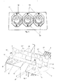
- the high-voltage electric connection (4) between the high-voltage switchgear (1) and the transformer (2), as well as the low-voltage electric connection (7) between the transformer (2) and the low-voltage switchboard (3) are carried out directly on the upper cover (5) of the transformer (2), as shown in Figures 4 and 5 .
- the coupling means (13) and (21) are made up of male-type transformer bushings.
- connection device (8) comprises at least one first connection element (12) configured for the direct connection to the mentioned first coupling means (13) of the transformer (2).
- connection device (8) comprises at least one second connection element (12') configured for the direct connection to second coupling means (14) of the high-voltage switchgear (1).
- connection device (8) is encapsulated in at least one solid insulating body (19) of high electric resistance, such that it allows reducing the insulation distances between phases, without needing to use any independent bay or gas as an insulation medium, which in short allows reducing the dimensions of the transformer substation to be installed.
- connection device (8) comprises measurement/control means (9), such as, for example, voltage sensors, voltage transformers, intensity sensors, means for receiving/transmitting signals via PLC or means for detecting partial discharges.
- Said device (8) additionally comprises encapsulated therein at least one protective element (16) for protecting against high fault currents, such as a fuse, for example.
- the mentioned measurement/control means (9) are associated with at least one control/protection device (10) integrated in the high-voltage switchgear (1) as shown in Figure 5 .
- said control/protection device (10) allows carrying out the control and the protection of the transformer substation (6), i.e., the control/protection device (10) allows identifying the problems or incidents that may arise in said transformer substation (6), communicating them to the operator remotely or face-to-face, collecting and storing the parameters for detecting the failures, indicating the reason for the disconnection of the transformer substation (6) and ordering the opening of at least one switch (11) for the disconnection of the mentioned substation (6).
- the combination of the measurement/control means (9) with the control/protection device (10) allows having an integral protection unit which prevents disturbances of the high-voltage and low-voltage network, by isolating the transformer substation (6) in a malfunction.
- the aforementioned protective element (16) is a supporting protection which only acts against high fault currents, such as internal solid short circuits in the transformer unit (2), for example. Only in this type of failure will the switch (11) be triggered by the melting of the supporting fuse (16) by means of the electronic combination with the control/protection device (10) and an indication of the phase in a malfunction.
- the combination of the protective element (16) plus the control/protection device (10) allows using a switch (11) with fewer features, whereby reducing the end costs of the transformer substation (6).
- the control/protection device (10) has indication means for indicating the reason for the trigger and orders the opening of the switch (11) as a consequence of:
- control/protection device (10) has means for estimating the remaining service life of the transformer unit (2).
- connection device (8) comprises at least one additional connection element (12") which allows installing the measurement/control means (9) through third coupling means (15).
- first, second and third coupling means (13, 14, 15) can consist of female-type bushings, male-type bushings and their combinations or of a closure plug to assure insulation has been contemplated.
- the second coupling means (14) can comprise standardizing shields (17) for standardizing the electric field which allow the capacitive voltage tap has been contemplated.
- the measurement/control means (9) can comprise at least one transformer or toroidal sensing device (18) installed on the outside and in the base of the coupling means (14), as shown in Figure 3 .
Landscapes
- Engineering & Computer Science (AREA)
- Power Engineering (AREA)
- Gas-Insulated Switchgears (AREA)
- Emergency Protection Circuit Devices (AREA)
- Connector Housings Or Holding Contact Members (AREA)
Priority Applications (1)
| Application Number | Priority Date | Filing Date | Title |
|---|---|---|---|
| PL10763198T PL2600363T3 (pl) | 2010-07-28 | 2010-07-28 | Urządzenie łączące dla modułów podstacji transformatorowych |
Applications Claiming Priority (1)
| Application Number | Priority Date | Filing Date | Title |
|---|---|---|---|
| PCT/ES2010/070524 WO2012013831A1 (fr) | 2010-07-28 | 2010-07-28 | Dispositif de connexion pour modules d'alimentation de transformateurs |
Publications (2)
| Publication Number | Publication Date |
|---|---|
| EP2600363A1 true EP2600363A1 (fr) | 2013-06-05 |
| EP2600363B1 EP2600363B1 (fr) | 2017-09-06 |
Family
ID=43901036
Family Applications (1)
| Application Number | Title | Priority Date | Filing Date |
|---|---|---|---|
| EP10763198.8A Not-in-force EP2600363B1 (fr) | 2010-07-28 | 2010-07-28 | Dispositif de connexion pour modules d'alimentation de transformateurs |
Country Status (7)
| Country | Link |
|---|---|
| US (1) | US9246325B2 (fr) |
| EP (1) | EP2600363B1 (fr) |
| CN (1) | CN103238192B (fr) |
| BR (1) | BR112013002050A2 (fr) |
| ES (1) | ES2655075T3 (fr) |
| PL (1) | PL2600363T3 (fr) |
| WO (1) | WO2012013831A1 (fr) |
Cited By (2)
| Publication number | Priority date | Publication date | Assignee | Title |
|---|---|---|---|---|
| EP3236272A1 (fr) * | 2016-04-19 | 2017-10-25 | Ormazabal Protection & Automation, S.L.U. | Dispositif d'isolation d'entrée haute tension |
| WO2024025547A1 (fr) * | 2022-07-29 | 2024-02-01 | Siemens Energy Global GmbH & Co. KG | Sous-station à transformateur de tension d'alimentation connectée par l'intermédiaire d'un dispositif de circuit à une ligne de transmission haute ou extra-haute tension |
Families Citing this family (16)
| Publication number | Priority date | Publication date | Assignee | Title |
|---|---|---|---|---|
| US9430012B2 (en) * | 2012-12-11 | 2016-08-30 | General Electric Company | Systems and methods of transformer failure detection and control |
| JP6257267B2 (ja) * | 2013-10-30 | 2018-01-10 | 三菱電機株式会社 | 電気機器接続装置及び当該装置を使用した縮小形受配電設備 |
| BR112017011707A2 (pt) * | 2014-12-09 | 2018-02-27 | Alstom Technology Ltd | dispositivo e método de medição de temperatura, estação de distribuição, programa de computador e meio de registro legível |
| US10008317B2 (en) | 2015-12-08 | 2018-06-26 | Smart Wires Inc. | Voltage or impedance-injection method using transformers with multiple secondary windings for dynamic power flow control |
| US10903653B2 (en) | 2015-12-08 | 2021-01-26 | Smart Wires Inc. | Voltage agnostic power reactor |
| US10180696B2 (en) | 2015-12-08 | 2019-01-15 | Smart Wires Inc. | Distributed impedance injection module for mitigation of the Ferranti effect |
| US10418814B2 (en) | 2015-12-08 | 2019-09-17 | Smart Wires Inc. | Transformers with multi-turn primary windings for dynamic power flow control |
| US10199150B2 (en) | 2015-12-10 | 2019-02-05 | Smart Wires Inc. | Power transmission tower mounted series injection transformer |
| US10097037B2 (en) | 2016-02-11 | 2018-10-09 | Smart Wires Inc. | System and method for distributed grid control with sub-cyclic local response capability |
| US10218175B2 (en) | 2016-02-11 | 2019-02-26 | Smart Wires Inc. | Dynamic and integrated control of total power system using distributed impedance injection modules and actuator devices within and at the edge of the power grid |
| US10651633B2 (en) | 2016-04-22 | 2020-05-12 | Smart Wires Inc. | Modular, space-efficient structures mounting multiple electrical devices |
| US10468880B2 (en) | 2016-11-15 | 2019-11-05 | Smart Wires Inc. | Systems and methods for voltage regulation using split-conductors with loop current reduction |
| US10685778B2 (en) * | 2017-04-12 | 2020-06-16 | Carte International Inc. | Intra-tank under-oil vacuum primary switches for medium voltage transformer applications |
| US10666038B2 (en) | 2017-06-30 | 2020-05-26 | Smart Wires Inc. | Modular FACTS devices with external fault current protection |
| CN114843919B (zh) * | 2021-02-02 | 2024-06-25 | 中国石油天然气集团有限公司 | 预装式变电站 |
| CN113451894B (zh) * | 2021-08-02 | 2025-05-27 | 沈阳日丰成控电气制造有限公司 | 一种预装式箱变控制电路 |
Family Cites Families (21)
| Publication number | Priority date | Publication date | Assignee | Title |
|---|---|---|---|---|
| BE572284A (fr) * | ||||
| US3868616A (en) * | 1967-08-15 | 1975-02-25 | Edward H Yonkers | Grounded surface distribution apparatus |
| US3513425A (en) | 1969-05-21 | 1970-05-19 | Gen Electric | Modular electrical conductor termination system |
| US3878434A (en) * | 1973-12-10 | 1975-04-15 | Leeds & Northrup Co | Power-limiting electrical barrier device |
| US4242713A (en) * | 1979-10-25 | 1980-12-30 | Goodrich Edward W | Triac output asymmetry detector |
| FR2530067A1 (fr) * | 1982-07-07 | 1984-01-13 | Bignolles Yves | Piece d'isolement pour borne de transformateur moyenne tension |
| DE9202127U1 (de) | 1992-02-19 | 1992-05-07 | Fritz Driescher KG Spezialfabrik für Elektrizitätswerksbedarf GmbH & Co, 5144 Wegberg | Kompaktstation mit Druckentlastungseinrichtung |
| DE19539060A1 (de) * | 1995-10-20 | 1997-04-24 | Efen Elektrotech Fab | Hochspannungs-Hochleistungs-Sicherung für eine elektrische Verbindungsleitung |
| FR2782418B1 (fr) * | 1998-08-14 | 2000-09-15 | Schneider Electric Ind Sa | Poste de transformation electrique compact |
| ES2155037B1 (es) | 1999-07-16 | 2001-12-01 | Schneider Electric Espana Sa | Centro de transformacion integrado. |
| US6295190B1 (en) * | 1999-10-26 | 2001-09-25 | Electric Boat Corporation | Circuit breaker arrangement with integrated protection, control and monitoring |
| US6583977B1 (en) * | 1999-10-27 | 2003-06-24 | Motorola, Inc. | Zipper fuse |
| FR2822601B1 (fr) | 2001-03-21 | 2004-12-24 | Transfix Toulon Soc Nouv | Poste de transformation evolutif pour reseaux en coupure d'artere |
| FR2826194B1 (fr) | 2001-06-14 | 2003-09-26 | Alstom | Bac de securite pour la retention de fluides dielectriques dans un poste de transformation et de distribution moyenne tension, et poste comportant un tel bac |
| EP1439622A1 (fr) * | 2001-10-05 | 2004-07-21 | Grupo Ormazabal, S.A. | Centre de transformation modulaire compact |
| FR2833769B1 (fr) | 2001-12-19 | 2004-12-24 | Transfix Toulon Soc Nouv | Ensemble moyenne tension associant un tableau mt et un transformateur |
| FR2842038B1 (fr) | 2002-07-04 | 2004-08-06 | Alstom | Poste mobile moyenne tension avec un tableau basse tension amovible |
| WO2004012312A1 (fr) | 2002-07-25 | 2004-02-05 | Grupo Ormazabal, S.A. | Centre de transformation modulaire aux dimensions reduites |
| FR2881001B1 (fr) | 2005-01-19 | 2007-07-13 | Transfix Toulon Sa Sa Soc Nouv | Infrastructure de poste de transformation electrique |
| FR2905532B1 (fr) | 2006-09-01 | 2009-12-18 | Transfix Toulon Sa Soc Nouv | Poste de transformation prefabrique compact |
| DE102007057017A1 (de) * | 2007-11-23 | 2009-05-28 | Siemens Ag | Anordnung mit einem Schaltgerät und einem Transformator |
-
2010
- 2010-07-28 ES ES10763198.8T patent/ES2655075T3/es active Active
- 2010-07-28 EP EP10763198.8A patent/EP2600363B1/fr not_active Not-in-force
- 2010-07-28 BR BR112013002050A patent/BR112013002050A2/pt not_active IP Right Cessation
- 2010-07-28 PL PL10763198T patent/PL2600363T3/pl unknown
- 2010-07-28 US US13/812,704 patent/US9246325B2/en not_active Expired - Fee Related
- 2010-07-28 CN CN201080068713.1A patent/CN103238192B/zh not_active Expired - Fee Related
- 2010-07-28 WO PCT/ES2010/070524 patent/WO2012013831A1/fr not_active Ceased
Non-Patent Citations (1)
| Title |
|---|
| See references of WO2012013831A1 * |
Cited By (4)
| Publication number | Priority date | Publication date | Assignee | Title |
|---|---|---|---|---|
| EP3236272A1 (fr) * | 2016-04-19 | 2017-10-25 | Ormazabal Protection & Automation, S.L.U. | Dispositif d'isolation d'entrée haute tension |
| WO2017182689A3 (fr) * | 2016-04-19 | 2018-03-22 | Ormazabal Protection & Automation, S.L.U. | Dispositif isolateur passant haute tension |
| US10908185B2 (en) | 2016-04-19 | 2021-02-02 | Ormazabal Protection & Automation, S.L.U. | High-voltage lead-in insulating device |
| WO2024025547A1 (fr) * | 2022-07-29 | 2024-02-01 | Siemens Energy Global GmbH & Co. KG | Sous-station à transformateur de tension d'alimentation connectée par l'intermédiaire d'un dispositif de circuit à une ligne de transmission haute ou extra-haute tension |
Also Published As
| Publication number | Publication date |
|---|---|
| CN103238192A (zh) | 2013-08-07 |
| PL2600363T3 (pl) | 2018-05-30 |
| US9246325B2 (en) | 2016-01-26 |
| US20130182355A1 (en) | 2013-07-18 |
| ES2655075T3 (es) | 2018-02-16 |
| EP2600363B1 (fr) | 2017-09-06 |
| WO2012013831A1 (fr) | 2012-02-02 |
| BR112013002050A2 (pt) | 2016-06-07 |
| CN103238192B (zh) | 2016-01-20 |
Similar Documents
| Publication | Publication Date | Title |
|---|---|---|
| US9246325B2 (en) | Connection device for transformer substation modules | |
| US7612988B2 (en) | Switchgear with movable user interface module | |
| KR101449706B1 (ko) | 실시간 구간별 선로이상 및 고조파, 접지저항값을 측정 감지하여 이상 발생에 따른 차단, 복구기능을 갖는 수배전반 | |
| KR100990736B1 (ko) | 보호 배전반의 상태를 감시하고 제어하는 보호 시스템 | |
| CN113168981A (zh) | 低压板的开关和保护装置及包含开关和保护装置的低压板 | |
| KR101211834B1 (ko) | 배전 시스템 | |
| EP1439622A1 (fr) | Centre de transformation modulaire compact | |
| CN207719795U (zh) | 一种多角度电弧光综合保护系统 | |
| RU2737951C1 (ru) | Комплекс контроля и защиты электроустановки | |
| EP1533877B1 (fr) | Poste de transfomation compact | |
| RU2189681C1 (ru) | Комплектная трансформаторная подстанция | |
| KR200456906Y1 (ko) | 옥외용 전력 기기의 이상 검출 장치 | |
| Mohla et al. | Electrical safety by design | |
| EP1724803B1 (fr) | Dispositif électronique associable à un appareil électrique | |
| KR101854149B1 (ko) | 일체형 특고압 수전설비 | |
| EP1906190B1 (fr) | Dispositif de commande/de protection pour reseaux de distribution electrique | |
| KR102649248B1 (ko) | 차단기 직접 연결 설치 구조의 지능형 서지보호기 | |
| EP4404229B1 (fr) | Base tripolaire automatisée comportant un dispositif de manoeuvre et de protection pour tableau basse tension et tableau basse tension contenant ladite base tripolaire automatisée | |
| US6359765B1 (en) | Fused terminal for use with a network protector | |
| KR100571291B1 (ko) | 특별고압 수전설비 | |
| KR101008234B1 (ko) | 접지가 형성된 특별고압 수변전설비 | |
| KR20100058443A (ko) | 접지상태를 식별할 수 있는 수배전장치 | |
| Kries et al. | Application of a Permanent Voltage Detection and Indication System (VDIS) for Reliable Personnel Safety and Monitoring of the Presence of Power in Switchgear Equipment; Experiences from the IEC Market for the US | |
| US9190225B2 (en) | Remotely operable electrical disconnect apparatus | |
| Tobias et al. | The building blocks of a distribution telecontrol system |
Legal Events
| Date | Code | Title | Description |
|---|---|---|---|
| PUAI | Public reference made under article 153(3) epc to a published international application that has entered the european phase |
Free format text: ORIGINAL CODE: 0009012 |
|
| 17P | Request for examination filed |
Effective date: 20130301 |
|
| AK | Designated contracting states |
Kind code of ref document: A1 Designated state(s): AL AT BE BG CH CY CZ DE DK EE ES FI FR GB GR HR HU IE IS IT LI LT LU LV MC MK MT NL NO PL PT RO SE SI SK SM TR |
|
| DAX | Request for extension of the european patent (deleted) | ||
| 17Q | First examination report despatched |
Effective date: 20140704 |
|
| GRAP | Despatch of communication of intention to grant a patent |
Free format text: ORIGINAL CODE: EPIDOSNIGR1 |
|
| STAA | Information on the status of an ep patent application or granted ep patent |
Free format text: STATUS: GRANT OF PATENT IS INTENDED |
|
| INTG | Intention to grant announced |
Effective date: 20170317 |
|
| RAP1 | Party data changed (applicant data changed or rights of an application transferred) |
Owner name: ORMAZABAL Y CIA., S.L.U. |
|
| GRAS | Grant fee paid |
Free format text: ORIGINAL CODE: EPIDOSNIGR3 |
|
| GRAA | (expected) grant |
Free format text: ORIGINAL CODE: 0009210 |
|
| STAA | Information on the status of an ep patent application or granted ep patent |
Free format text: STATUS: THE PATENT HAS BEEN GRANTED |
|
| AK | Designated contracting states |
Kind code of ref document: B1 Designated state(s): AL AT BE BG CH CY CZ DE DK EE ES FI FR GB GR HR HU IE IS IT LI LT LU LV MC MK MT NL NO PL PT RO SE SI SK SM TR |
|
| REG | Reference to a national code |
Ref country code: GB Ref legal event code: FG4D |
|
| REG | Reference to a national code |
Ref country code: CH Ref legal event code: EP Ref country code: AT Ref legal event code: REF Ref document number: 926687 Country of ref document: AT Kind code of ref document: T Effective date: 20170915 |
|
| REG | Reference to a national code |
Ref country code: IE Ref legal event code: FG4D |
|
| REG | Reference to a national code |
Ref country code: DE Ref legal event code: R096 Ref document number: 602010045047 Country of ref document: DE |
|
| REG | Reference to a national code |
Ref country code: NL Ref legal event code: MP Effective date: 20170906 |
|
| REG | Reference to a national code |
Ref country code: LT Ref legal event code: MG4D |
|
| PG25 | Lapsed in a contracting state [announced via postgrant information from national office to epo] |
Ref country code: LT Free format text: LAPSE BECAUSE OF FAILURE TO SUBMIT A TRANSLATION OF THE DESCRIPTION OR TO PAY THE FEE WITHIN THE PRESCRIBED TIME-LIMIT Effective date: 20170906 Ref country code: SE Free format text: LAPSE BECAUSE OF FAILURE TO SUBMIT A TRANSLATION OF THE DESCRIPTION OR TO PAY THE FEE WITHIN THE PRESCRIBED TIME-LIMIT Effective date: 20170906 Ref country code: FI Free format text: LAPSE BECAUSE OF FAILURE TO SUBMIT A TRANSLATION OF THE DESCRIPTION OR TO PAY THE FEE WITHIN THE PRESCRIBED TIME-LIMIT Effective date: 20170906 Ref country code: HR Free format text: LAPSE BECAUSE OF FAILURE TO SUBMIT A TRANSLATION OF THE DESCRIPTION OR TO PAY THE FEE WITHIN THE PRESCRIBED TIME-LIMIT Effective date: 20170906 Ref country code: NO Free format text: LAPSE BECAUSE OF FAILURE TO SUBMIT A TRANSLATION OF THE DESCRIPTION OR TO PAY THE FEE WITHIN THE PRESCRIBED TIME-LIMIT Effective date: 20171206 |
|
| REG | Reference to a national code |
Ref country code: AT Ref legal event code: MK05 Ref document number: 926687 Country of ref document: AT Kind code of ref document: T Effective date: 20170906 Ref country code: CH Ref legal event code: NV Representative=s name: PATENTANWAELTE SCHAAD, BALASS, MENZL AND PARTN, CH |
|
| REG | Reference to a national code |
Ref country code: ES Ref legal event code: FG2A Ref document number: 2655075 Country of ref document: ES Kind code of ref document: T3 Effective date: 20180216 |
|
| PG25 | Lapsed in a contracting state [announced via postgrant information from national office to epo] |
Ref country code: LV Free format text: LAPSE BECAUSE OF FAILURE TO SUBMIT A TRANSLATION OF THE DESCRIPTION OR TO PAY THE FEE WITHIN THE PRESCRIBED TIME-LIMIT Effective date: 20170906 Ref country code: BG Free format text: LAPSE BECAUSE OF FAILURE TO SUBMIT A TRANSLATION OF THE DESCRIPTION OR TO PAY THE FEE WITHIN THE PRESCRIBED TIME-LIMIT Effective date: 20171206 |
|
| PG25 | Lapsed in a contracting state [announced via postgrant information from national office to epo] |
Ref country code: NL Free format text: LAPSE BECAUSE OF FAILURE TO SUBMIT A TRANSLATION OF THE DESCRIPTION OR TO PAY THE FEE WITHIN THE PRESCRIBED TIME-LIMIT Effective date: 20170906 |
|
| PG25 | Lapsed in a contracting state [announced via postgrant information from national office to epo] |
Ref country code: RO Free format text: LAPSE BECAUSE OF FAILURE TO SUBMIT A TRANSLATION OF THE DESCRIPTION OR TO PAY THE FEE WITHIN THE PRESCRIBED TIME-LIMIT Effective date: 20170906 Ref country code: CZ Free format text: LAPSE BECAUSE OF FAILURE TO SUBMIT A TRANSLATION OF THE DESCRIPTION OR TO PAY THE FEE WITHIN THE PRESCRIBED TIME-LIMIT Effective date: 20170906 |
|
| PG25 | Lapsed in a contracting state [announced via postgrant information from national office to epo] |
Ref country code: IT Free format text: LAPSE BECAUSE OF FAILURE TO SUBMIT A TRANSLATION OF THE DESCRIPTION OR TO PAY THE FEE WITHIN THE PRESCRIBED TIME-LIMIT Effective date: 20170906 Ref country code: SK Free format text: LAPSE BECAUSE OF FAILURE TO SUBMIT A TRANSLATION OF THE DESCRIPTION OR TO PAY THE FEE WITHIN THE PRESCRIBED TIME-LIMIT Effective date: 20170906 Ref country code: EE Free format text: LAPSE BECAUSE OF FAILURE TO SUBMIT A TRANSLATION OF THE DESCRIPTION OR TO PAY THE FEE WITHIN THE PRESCRIBED TIME-LIMIT Effective date: 20170906 Ref country code: AT Free format text: LAPSE BECAUSE OF FAILURE TO SUBMIT A TRANSLATION OF THE DESCRIPTION OR TO PAY THE FEE WITHIN THE PRESCRIBED TIME-LIMIT Effective date: 20170906 Ref country code: SM Free format text: LAPSE BECAUSE OF FAILURE TO SUBMIT A TRANSLATION OF THE DESCRIPTION OR TO PAY THE FEE WITHIN THE PRESCRIBED TIME-LIMIT Effective date: 20170906 Ref country code: IS Free format text: LAPSE BECAUSE OF FAILURE TO SUBMIT A TRANSLATION OF THE DESCRIPTION OR TO PAY THE FEE WITHIN THE PRESCRIBED TIME-LIMIT Effective date: 20180106 |
|
| REG | Reference to a national code |
Ref country code: DE Ref legal event code: R097 Ref document number: 602010045047 Country of ref document: DE |
|
| PLBE | No opposition filed within time limit |
Free format text: ORIGINAL CODE: 0009261 |
|
| STAA | Information on the status of an ep patent application or granted ep patent |
Free format text: STATUS: NO OPPOSITION FILED WITHIN TIME LIMIT |
|
| PG25 | Lapsed in a contracting state [announced via postgrant information from national office to epo] |
Ref country code: DK Free format text: LAPSE BECAUSE OF FAILURE TO SUBMIT A TRANSLATION OF THE DESCRIPTION OR TO PAY THE FEE WITHIN THE PRESCRIBED TIME-LIMIT Effective date: 20170906 |
|
| 26N | No opposition filed |
Effective date: 20180607 |
|
| PG25 | Lapsed in a contracting state [announced via postgrant information from national office to epo] |
Ref country code: SI Free format text: LAPSE BECAUSE OF FAILURE TO SUBMIT A TRANSLATION OF THE DESCRIPTION OR TO PAY THE FEE WITHIN THE PRESCRIBED TIME-LIMIT Effective date: 20170906 |
|
| REG | Reference to a national code |
Ref country code: DE Ref legal event code: R119 Ref document number: 602010045047 Country of ref document: DE |
|
| REG | Reference to a national code |
Ref country code: CH Ref legal event code: PL |
|
| GBPC | Gb: european patent ceased through non-payment of renewal fee |
Effective date: 20180728 |
|
| PG25 | Lapsed in a contracting state [announced via postgrant information from national office to epo] |
Ref country code: LU Free format text: LAPSE BECAUSE OF NON-PAYMENT OF DUE FEES Effective date: 20180728 Ref country code: MC Free format text: LAPSE BECAUSE OF FAILURE TO SUBMIT A TRANSLATION OF THE DESCRIPTION OR TO PAY THE FEE WITHIN THE PRESCRIBED TIME-LIMIT Effective date: 20170906 |
|
| REG | Reference to a national code |
Ref country code: BE Ref legal event code: MM Effective date: 20180731 |
|
| PG25 | Lapsed in a contracting state [announced via postgrant information from national office to epo] |
Ref country code: FR Free format text: LAPSE BECAUSE OF NON-PAYMENT OF DUE FEES Effective date: 20180731 Ref country code: GB Free format text: LAPSE BECAUSE OF NON-PAYMENT OF DUE FEES Effective date: 20180728 Ref country code: LI Free format text: LAPSE BECAUSE OF NON-PAYMENT OF DUE FEES Effective date: 20180731 Ref country code: DE Free format text: LAPSE BECAUSE OF NON-PAYMENT OF DUE FEES Effective date: 20190201 Ref country code: CH Free format text: LAPSE BECAUSE OF NON-PAYMENT OF DUE FEES Effective date: 20180731 |
|
| REG | Reference to a national code |
Ref country code: IE Ref legal event code: MM4A |
|
| PG25 | Lapsed in a contracting state [announced via postgrant information from national office to epo] |
Ref country code: BE Free format text: LAPSE BECAUSE OF NON-PAYMENT OF DUE FEES Effective date: 20180731 |
|
| PG25 | Lapsed in a contracting state [announced via postgrant information from national office to epo] |
Ref country code: IE Free format text: LAPSE BECAUSE OF NON-PAYMENT OF DUE FEES Effective date: 20180728 |
|
| PG25 | Lapsed in a contracting state [announced via postgrant information from national office to epo] |
Ref country code: MT Free format text: LAPSE BECAUSE OF NON-PAYMENT OF DUE FEES Effective date: 20180728 |
|
| PG25 | Lapsed in a contracting state [announced via postgrant information from national office to epo] |
Ref country code: PL Free format text: LAPSE BECAUSE OF NON-PAYMENT OF DUE FEES Effective date: 20180728 |
|
| PG25 | Lapsed in a contracting state [announced via postgrant information from national office to epo] |
Ref country code: HU Free format text: LAPSE BECAUSE OF FAILURE TO SUBMIT A TRANSLATION OF THE DESCRIPTION OR TO PAY THE FEE WITHIN THE PRESCRIBED TIME-LIMIT; INVALID AB INITIO Effective date: 20100728 Ref country code: PT Free format text: LAPSE BECAUSE OF FAILURE TO SUBMIT A TRANSLATION OF THE DESCRIPTION OR TO PAY THE FEE WITHIN THE PRESCRIBED TIME-LIMIT Effective date: 20170906 |
|
| PG25 | Lapsed in a contracting state [announced via postgrant information from national office to epo] |
Ref country code: CY Free format text: LAPSE BECAUSE OF FAILURE TO SUBMIT A TRANSLATION OF THE DESCRIPTION OR TO PAY THE FEE WITHIN THE PRESCRIBED TIME-LIMIT Effective date: 20170906 Ref country code: GR Free format text: LAPSE BECAUSE OF FAILURE TO SUBMIT A TRANSLATION OF THE DESCRIPTION OR TO PAY THE FEE WITHIN THE PRESCRIBED TIME-LIMIT Effective date: 20170906 Ref country code: MK Free format text: LAPSE BECAUSE OF NON-PAYMENT OF DUE FEES Effective date: 20170906 |
|
| PG25 | Lapsed in a contracting state [announced via postgrant information from national office to epo] |
Ref country code: AL Free format text: LAPSE BECAUSE OF FAILURE TO SUBMIT A TRANSLATION OF THE DESCRIPTION OR TO PAY THE FEE WITHIN THE PRESCRIBED TIME-LIMIT Effective date: 20170906 |
|
| PGFP | Annual fee paid to national office [announced via postgrant information from national office to epo] |
Ref country code: ES Payment date: 20210804 Year of fee payment: 12 |
|
| REG | Reference to a national code |
Ref country code: ES Ref legal event code: FD2A Effective date: 20230901 |
|
| PG25 | Lapsed in a contracting state [announced via postgrant information from national office to epo] |
Ref country code: ES Free format text: LAPSE BECAUSE OF NON-PAYMENT OF DUE FEES Effective date: 20220729 |
|
| PG25 | Lapsed in a contracting state [announced via postgrant information from national office to epo] |
Ref country code: TR Free format text: LAPSE BECAUSE OF NON-PAYMENT OF DUE FEES Effective date: 20180728 |