EP2600367A1 - Appareil de commutation pour applications à courant continu - Google Patents
Appareil de commutation pour applications à courant continu Download PDFInfo
- Publication number
- EP2600367A1 EP2600367A1 EP11191219.2A EP11191219A EP2600367A1 EP 2600367 A1 EP2600367 A1 EP 2600367A1 EP 11191219 A EP11191219 A EP 11191219A EP 2600367 A1 EP2600367 A1 EP 2600367A1
- Authority
- EP
- European Patent Office
- Prior art keywords
- switching
- contact
- arrangement
- arc
- switching device
- Prior art date
- Legal status (The legal status is an assumption and is not a legal conclusion. Google has not performed a legal analysis and makes no representation as to the accuracy of the status listed.)
- Withdrawn
Links
- 238000010791 quenching Methods 0.000 claims description 9
- 230000000171 quenching effect Effects 0.000 claims description 9
- 238000005192 partition Methods 0.000 claims description 4
- 238000000926 separation method Methods 0.000 claims description 4
- OKTJSMMVPCPJKN-UHFFFAOYSA-N Carbon Chemical compound [C] OKTJSMMVPCPJKN-UHFFFAOYSA-N 0.000 description 1
- 230000008033 biological extinction Effects 0.000 description 1
- 229910052799 carbon Inorganic materials 0.000 description 1
- 230000000694 effects Effects 0.000 description 1
- 210000003746 feather Anatomy 0.000 description 1
- 230000005415 magnetization Effects 0.000 description 1
Images
Classifications
-
- H—ELECTRICITY
- H01—ELECTRIC ELEMENTS
- H01H—ELECTRIC SWITCHES; RELAYS; SELECTORS; EMERGENCY PROTECTIVE DEVICES
- H01H33/00—High-tension or heavy-current switches with arc-extinguishing or arc-preventing means
- H01H33/02—Details
- H01H33/04—Means for extinguishing or preventing arc between current-carrying parts
- H01H33/18—Means for extinguishing or preventing arc between current-carrying parts using blow-out magnet
- H01H33/182—Means for extinguishing or preventing arc between current-carrying parts using blow-out magnet using permanent magnets
-
- H—ELECTRICITY
- H01—ELECTRIC ELEMENTS
- H01H—ELECTRIC SWITCHES; RELAYS; SELECTORS; EMERGENCY PROTECTIVE DEVICES
- H01H1/00—Contacts
- H01H1/12—Contacts characterised by the manner in which co-operating contacts engage
- H01H1/14—Contacts characterised by the manner in which co-operating contacts engage by abutting
- H01H1/20—Bridging contacts
- H01H1/2025—Bridging contacts comprising two-parallel bridges
-
- H—ELECTRICITY
- H01—ELECTRIC ELEMENTS
- H01H—ELECTRIC SWITCHES; RELAYS; SELECTORS; EMERGENCY PROTECTIVE DEVICES
- H01H33/00—High-tension or heavy-current switches with arc-extinguishing or arc-preventing means
- H01H33/02—Details
- H01H33/04—Means for extinguishing or preventing arc between current-carrying parts
- H01H33/08—Stationary parts for restricting or subdividing the arc, e.g. barrier plate
-
- H—ELECTRICITY
- H01—ELECTRIC ELEMENTS
- H01H—ELECTRIC SWITCHES; RELAYS; SELECTORS; EMERGENCY PROTECTIVE DEVICES
- H01H9/00—Details of switching devices, not covered by groups H01H1/00 - H01H7/00
- H01H9/30—Means for extinguishing or preventing arc between current-carrying parts
- H01H9/34—Stationary parts for restricting or subdividing the arc, e.g. barrier plate
-
- H—ELECTRICITY
- H01—ELECTRIC ELEMENTS
- H01H—ELECTRIC SWITCHES; RELAYS; SELECTORS; EMERGENCY PROTECTIVE DEVICES
- H01H9/00—Details of switching devices, not covered by groups H01H1/00 - H01H7/00
- H01H9/30—Means for extinguishing or preventing arc between current-carrying parts
- H01H9/44—Means for extinguishing or preventing arc between current-carrying parts using blow-out magnet
- H01H9/443—Means for extinguishing or preventing arc between current-carrying parts using blow-out magnet using permanent magnets
-
- H—ELECTRICITY
- H01—ELECTRIC ELEMENTS
- H01H—ELECTRIC SWITCHES; RELAYS; SELECTORS; EMERGENCY PROTECTIVE DEVICES
- H01H33/00—High-tension or heavy-current switches with arc-extinguishing or arc-preventing means
- H01H33/02—Details
- H01H33/59—Circuit arrangements not adapted to a particular application of the switch and not otherwise provided for, e.g. for ensuring operation of the switch at a predetermined point in the AC cycle
- H01H33/596—Circuit arrangements not adapted to a particular application of the switch and not otherwise provided for, e.g. for ensuring operation of the switch at a predetermined point in the AC cycle for interrupting DC
Definitions
- the invention relates to a switching device for DC applications.
- the switching device comprises at least a first switching chamber for a first current path and a second switching chamber for a second current path, each current path at least one switching contact arrangement having a first contact and a second contact, wherein the two contacts in an on state of the switching device in contact and in a disconnected state of the switching device forming an isolating distance are kept out of contact with each other, and each current path at least one quenching device for erasing an arc occurring between the contacts.
- Such a switching device is from the EP 2 061 053 A2 known.
- a switching device for DC applications there is proposed to use the housing of a switching device for AC applications, in addition, at least two permanent magnets are provided which have a magnetic field with substantially transverse to the separation distance of the current paths field lines.
- three switching chambers are provided in each case for a current path, each current path being assigned a movable switching contact element and two mutually opposite stationary switching contact elements.
- the three movable switching contact elements are in this case jointly movable between a closed position, which corresponds to the switched-on state of the switching device, and an open position, which corresponds to the switched-off state of the switching device.
- each current path has two separating sections, which, when the movable switching contact elements are open, extend between the ends thereof and the first and second stationary switching contact elements assigned to these ends form. When the switching contact elements are opened, an arc forms along the separating sections, which arc can be extinguished with the aid of the arc-extinguishing devices.
- DC applications since erasure of an arc can not be achieved due to current zero crossing, as in AC applications, DC applications require the provision of a magnetic field which drives the arc into one of the arc quenching devices.
- a switching device for DC applications which has at least a first switching chamber for a first current path and a second switching chamber for a second current path.
- At least one switching contact arrangement is provided for each current path, which has a first contact and a second contact, wherein the two contacts are kept in contact with one another in an on state of the switching device and in an off state of the switching device an isolating distance is formed.
- at least one extinguishing device is furthermore provided for extinguishing an arc occurring between the contacts.
- an arc runner arrangement is provided which is arranged in one of the two switching chambers and at least in the region of the switching contact arrangement of the respective current path generates a magnetic field in order to drive the arc into the respective extinguishing device.
- the switching device has a switching chamber in which a Lichtbogentreiberan Aunt is provided, and a switching chamber in which no arc running arrangement is provided.
- the switching device is therefore suitable for both lower currents and high currents.
- the switching chamber with arc runner arrangement is suitable for lower currents, in which the risk is low that an arc on the arc guide assembly rolls over.
- the magnetic field of the arc runner assembly is also strong enough to drive arcs of a smaller current quickly into the quenching device.
- the switching chamber without arc runner arrangement is particularly suitable for high currents, since no arc runner arrangement is arranged in this switching chamber and thus the arc can not overturn on such an arc runner arrangement.
- the two switching chambers of the switching device are arranged side by side, so that the magnetic field of the arc runner assembly also radiates to the switching chamber without arc runner assembly and generates a Lorentz force on a resulting there arc.
- the current paths are preferably arranged next to one another and parallel to one another.
- the switching chambers can be formed separately from each other, in particular in a housing of the switching device by intermediate walls, wherein the intermediate walls are preferably made of an electrically insulating but magnetically permeable material.
- the two current paths can be used depending on the application, ie at low currents occurring the current path is used with arc runner assembly and at high currents occurring the current path is used without the arc runner assembly.
- the current paths can also be electrically connected in parallel or in series so that in principle current flows through both current paths and effects the extinction of an arc, depending on the occurring current intensity and the resulting quenching behavior of one of the two current paths. As a result, the maintained by the arcs Current flow interrupted at one point, so that all other arcs go out.
- a third switching chamber can also be provided for a third flow path. If the arc runner arrangement is then arranged in the second switching chamber, this can be arranged between the first switching chamber and the second switching chamber.
- the magnetic field of the arc runner assembly of the second switching chamber radiates to the other two, namely, the first switching chamber and the third switching chamber.
- an arc runner arrangement is arranged in the first switching chamber and the third switching chamber, and the second switching chamber, which is located between the first and the third switching chamber, is free of an arc runner arrangement.
- the arc runner assembly may include two permanent magnets disposed on opposite sides of the switch contact assembly that generate a magnetic field with field lines across the gap.
- the arc runner arrangement may consist of a permanent magnet, which is provided above the switching contact arrangement, and which is arranged between two pole plates, which are located laterally on opposite sides of the switching contact arrangement.
- At least one arc guide arrangement is provided per switching contact arrangement, by means of which the arc is directed to the extinguishing device of the respective switching contact arrangement.
- Such an arc guide arrangement usually consists of baffles which extend from the contacts in the direction of the respective extinguishing device.
- Each switching arrangement may basically consist of a fixed contact and a movable contact, wherein the first contacts are each arranged on a fixed contact carrier fixed in the switching chamber and the second contacts each arranged on a movable in the switching chamber Bridge arrangement are arranged.
- the bridge arrangement serves to actuate the second contact.
- a double interruption with two contact pairs can also be provided per current path, two contact arrangements being provided for each current path and the second contacts being arranged on a movable bridge contact piece and the second contacts being electrically connected to one another via the bridge contact element.
- the two contact pairs each consisting of a first contact and a second contact, are thus connected in series.
- arcs are formed between each contact pair.
- the bridge switching pieces of all current paths can be actuated by a common bridge arrangement, so that by actuation of an element, namely the bridge arrangement, all contact pairs or switching contact arrangements are actuated.
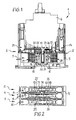
- FIG. 1 shows the switching device 1 according to the invention in a partial longitudinal section with a housing 2, which comprises a lower part 3 and an upper part 4.
- FIG. 2 shows a view into the switching device 1, wherein the upper part 4 is omitted so that you can look into the lower part 3.
- the two Figures 1 and 2 will be described together below.
- the switching device 1 has three poles, ie three switching paths, namely a first switching path 5, a second switching path 6 and a third switching path 7.
- Each switching path 5, 6, 7 is in a separate switching chamber, namely a first switching chamber 8, a second switching chamber 9 and a third switching chamber 10th arranged.
- the switching chambers 8, 9, 10 are electrically separated from each other by partitions 11, 12 of the housing 2, wherein the intermediate walls 11, 12 are preferably magnetically permeable.
- the three current paths 5, 6, 7 are identical in terms of their structure, wherein the structure of the current paths 5, 6, 7 is explained in more detail by way of example with reference to the middle second current path 6 in the following.
- the second flow path 6 within the second switching chamber 9 is in FIG. 1 shown in longitudinal section.
- the second switching path 6 is formed twice interrupting and has a first switching contact arrangement 13 and a second switching contact arrangement 16.
- the two switch contact arrangements 13, 16 are identical and mirror images of each other.
- the first switching contact arrangement 13, which in FIG. 1 is shown on the left side, comprises a contact pair with a first contact 14 and a second contact 15. Accordingly, the second switch contact arrangement 16 with a second contact pair comprising a first contact 17 and a second contact 18 is formed.
- the first contact 14 of the first switching contact arrangement 13 is arranged on a first fixed contact carrier 19.
- the first fixed contact carrier 19 is fixed and thus arranged immovably in the housing 2 of the switching device 1.
- the first contact 17 is arranged at a first free end of the first fixed contact carrier 19. At a this end facing away from the end of the first fixed contact carrier 19, a first terminal 23 is provided for the connection of the first current path 5 in a DC circuit.
- the second contact 15 of the first switch contact arrangement 13 is located on a bridge contact piece 20 of a bridge arrangement 21 and is movably arranged in the housing 2.
- the bridge contact piece 20 is in the in FIG. 1 Oriented orientation vertically adjustable between a raised and a lowered position. In the raised position, the second contact 15 of the first switching contact arrangement 13 is in contact with the first contact 14. In a lowered position, the two contacts 14, 15 are out of contact. In this position, an isolating distance is formed between the first contact 14 and the second contact 15 along which an arc can form.
- the second switching contact arrangement 16 is identical to the first switching contact arrangement 13.
- the first contact 17 of the second switching contact arrangement 16 is located on a second fixed contact carrier 22 and is arranged at a first end of the second fixed contact carrier 22. At a this end remote from the end of the second fixed contact carrier 22, a second terminal 24 is provided.
- the second contact 18 of the second switching contact arrangement 16 is likewise arranged on the bridge contact piece 20, specifically on an end remote from the second contact 15 of the first switching contact arrangement 13.
- the bridge switching piece 20 is electrically conductive and connects the two second contacts 15, 18 electrically to each other.
- the second contact 18 of the second switching arrangement 16 is in contact with the first contact 17, wherein in the lowered position of the bridge switching piece 20, the two contacts 17, 18 are kept out of contact and forms an insulating gap between them, along which can also form an arc.
- a current can thus flow from the first terminal 23 via the first fixed contact carrier 19 to the first contact of the first switching contact arrangement 13, then on to the second contact 15 of the first switching contact arrangement 13 via the bridge contact piece 20 to the second contact 18 of the second switching contact arrangement 16 , From there, the current continues to flow to the first contact 17 of the second switching contact arrangement 16 via the second fixed contact carrier 22 to the second connection 24.
- a switching bridge 30 is provided, which is arranged vertically displaceable in the housing 2 and the bridge switching piece 20 adjusted.
- the bridge switching piece 20 is pressed with its second contacts 15, 18 via a spring 31 against the first contacts 14, 17, wherein the spring 31 is supported between the bridge switching piece 20 and the switching bridge 30.
- two erasing devices namely a first erasing device 27 and a second erasing device 28 are provided.
- the first erasing device 27 is assigned to the first switching contact arrangement 13 and the second erasing device 28 to the second switching contact arrangement 16.
- the two erasing devices 27, 28 are each arranged on a side of the respective switching contact arrangement 13, 16 facing away from the switching bridge arrangement 21.
- the first arc runner arrangement 32 comprises two first permanent magnets 25, which are arranged within the second switching chamber 9 on the intermediate walls 11, 12 and receive the first switching contact arrangement 13 between them.
- the first permanent magnets 25 are designed plate-shaped and arranged parallel to the intermediate walls 11, 12.
- the two first permanent magnets 25 are arranged rectified with respect to their magnetization, so that forms an approximately homogeneous magnetic field with field lines transverse to the separation direction between them.
- the field lines of the magnetic field also extend transversely to an arc, which forms between the first contact 14 and the second contact 15 of the first switching contact arrangement 13.
- a Lorenz force is generated by the magnetic field, which acts on the arc and drives it in the direction of the first extinguishing device 27.
- the second arc driver assembly 33 is constructed similar to the first arc driver assembly 32 and includes two second ones Permanent magnets 26 which receive the second switching contact arrangement 16 between them.
- the magnetic field is in this case aligned in opposite to the magnetic field of the first permanent magnet 25.
- An arc, which forms between the first contact 17 and the second contact 18 of the second switching contact arrangement 16, has a current direction which is spatially opposite to the current direction of an arc between the contacts 14, 15 of the first switching contact arrangement 13. If an arc as shown in FIG. 1 between the contacts 17, 18 of the second switching contact arrangement 16 has a current direction vertically downward, an arc between the contacts 14, 15 of the first switching contact arrangement, a current direction vertically upwards.
- the first flow path 5 and the third flow path 7 as well as the first switching chamber 8 and the third switching chamber 10 are identical to the second flow path 6 and the second switching chamber 9, but with the difference that in the first switching chamber 8 and the third switching chamber 10 no arc drive arrangements are arranged. In the first switching chamber 8 and in the third switching chamber 10 thus no permanent magnets are arranged.
- the arc runner arrangements 32, 33 of the first current path 6 radiate to the adjacent switching chambers, namely the first switching chamber 8 and the third switching chamber 10, in order to be able to exert a Lorentz force on a developing arc there as well.
Landscapes
- Arc-Extinguishing Devices That Are Switches (AREA)
Priority Applications (5)
| Application Number | Priority Date | Filing Date | Title |
|---|---|---|---|
| EP11191219.2A EP2600367A1 (fr) | 2011-11-29 | 2011-11-29 | Appareil de commutation pour applications à courant continu |
| PL12777934T PL2786385T3 (pl) | 2011-11-29 | 2012-10-29 | Łącznik do zastosowań stałoprądowych |
| US14/360,954 US9552944B2 (en) | 2011-11-29 | 2012-10-29 | Switching device for direct current applications |
| EP12777934.6A EP2786385B1 (fr) | 2011-11-29 | 2012-10-29 | Appareil de commutation pour applications à courant continu |
| PCT/EP2012/071410 WO2013079269A1 (fr) | 2011-11-29 | 2012-10-29 | Appareil de coupure pour applications à courant continu |
Applications Claiming Priority (1)
| Application Number | Priority Date | Filing Date | Title |
|---|---|---|---|
| EP11191219.2A EP2600367A1 (fr) | 2011-11-29 | 2011-11-29 | Appareil de commutation pour applications à courant continu |
Publications (1)
| Publication Number | Publication Date |
|---|---|
| EP2600367A1 true EP2600367A1 (fr) | 2013-06-05 |
Family
ID=47073468
Family Applications (2)
| Application Number | Title | Priority Date | Filing Date |
|---|---|---|---|
| EP11191219.2A Withdrawn EP2600367A1 (fr) | 2011-11-29 | 2011-11-29 | Appareil de commutation pour applications à courant continu |
| EP12777934.6A Active EP2786385B1 (fr) | 2011-11-29 | 2012-10-29 | Appareil de commutation pour applications à courant continu |
Family Applications After (1)
| Application Number | Title | Priority Date | Filing Date |
|---|---|---|---|
| EP12777934.6A Active EP2786385B1 (fr) | 2011-11-29 | 2012-10-29 | Appareil de commutation pour applications à courant continu |
Country Status (4)
| Country | Link |
|---|---|
| US (1) | US9552944B2 (fr) |
| EP (2) | EP2600367A1 (fr) |
| PL (1) | PL2786385T3 (fr) |
| WO (1) | WO2013079269A1 (fr) |
Families Citing this family (12)
| Publication number | Priority date | Publication date | Assignee | Title |
|---|---|---|---|---|
| JP6548905B2 (ja) * | 2015-02-06 | 2019-07-24 | 富士通コンポーネント株式会社 | スイッチ |
| DE102017106300B4 (de) * | 2017-03-23 | 2023-07-27 | Schaltbau Gmbh | Schaltgerät mit verbesserter permanentmagnetischer Lichtbogenlöschung |
| US10236145B1 (en) * | 2017-11-22 | 2019-03-19 | Carling Technologies, Inc. | High voltage DC circuit breaker with double break contacts |
| DE102017223401B4 (de) * | 2017-12-20 | 2019-10-10 | Schunk Carbon Technology Gmbh | Kontakteinheit und Verfahren |
| EP3624157B1 (fr) * | 2018-09-17 | 2024-11-13 | Microelettrica Scientifica S.p.A. | Dispositif de commutation amélioré ou contacteur avec des capacités d'extinction d'arc élevées |
| CN113767472B (zh) * | 2019-03-04 | 2025-10-21 | 克莱米特有限责任公司 | 用于农业智能计算系统的数据存储和传送设备 |
| KR102196740B1 (ko) * | 2019-04-05 | 2020-12-30 | 엘에스일렉트릭(주) | 직류 기중 회로 차단기용 소호부 구조체 |
| FR3095890B1 (fr) * | 2019-05-06 | 2021-07-16 | Schneider Electric Ind Sas | Pôle limiteur d’interrupteur électrique et interrupteur électrique à courant continu comportant un tel pôle limiteur |
| DE102020104258B4 (de) * | 2020-02-18 | 2022-09-29 | Schaltbau Gmbh | Schaltgerät mit zumindest zwei miteinander kommunizierenden Löschbereichen |
| FR3123143A1 (fr) * | 2021-05-21 | 2022-11-25 | Socomec | Module de coupure électrique équipé d’un dispositif de soufflage magnétique et appareil de coupure électrique comportant un tel module |
| FR3126168B1 (fr) * | 2021-08-11 | 2023-10-20 | Safran Electrical & Power | Contacteur double coupure bi-directionnel |
| KR102542180B1 (ko) * | 2022-03-30 | 2023-06-14 | 오성기전 주식회사 | 직류 차단기의 아크 소호장치 |
Citations (4)
| Publication number | Priority date | Publication date | Assignee | Title |
|---|---|---|---|---|
| US2332446A (en) * | 1941-01-13 | 1943-10-19 | Allen Bradley Co | Permanent magnet blowout for electric switches |
| DE1246851B (de) * | 1962-12-06 | 1967-08-10 | Stotz Kontakt Gmbh | Lichtbogenloeschvorrichtung mit Permanentmagnet |
| DE3409564A1 (de) * | 1983-03-17 | 1984-09-20 | Fuji Electric Co., Ltd., Kawasaki, Kanagawa | Lichtbogenloescheinrichtung |
| EP2061053A2 (fr) | 2007-11-17 | 2009-05-20 | Moeller GmbH | Commutateur destiné à des applications à courant continu |
Family Cites Families (12)
| Publication number | Priority date | Publication date | Assignee | Title |
|---|---|---|---|---|
| US6480082B1 (en) * | 1996-12-25 | 2002-11-12 | Hitachi, Ltd. | Circuit breaker |
| US6437671B1 (en) * | 1999-08-30 | 2002-08-20 | Eaton Corporation | Circuit interrupter with secure base and terminal connection |
| US6995640B2 (en) * | 2000-05-16 | 2006-02-07 | General Electric Company | Pressure sensitive trip mechanism for circuit breakers |
| US6933814B2 (en) * | 2003-05-13 | 2005-08-23 | General Electric Company | Phase-to-phase isolation of cassette type circuit breakers |
| FR2916571B1 (fr) * | 2007-05-22 | 2009-09-11 | Schneider Electric Ind Sas | Chambre de coupure et disjoncteur equipe d'une telle chambre de coupure |
| US7633365B2 (en) * | 2007-06-28 | 2009-12-15 | General Electric Company | Circuit breaker apparatus |
| FR2938969A1 (fr) * | 2008-11-21 | 2010-05-28 | Schneider Electric Ind Sas | Dispositif de coupure pour couper un courant continu bidirectionnel et installation a cellules photovoltaiques equipee d'un tel dispositif |
| US8248194B2 (en) * | 2010-02-10 | 2012-08-21 | Siemens Industry, Inc. | Disconnect switch |
| US8222983B2 (en) * | 2010-12-08 | 2012-07-17 | Eaton Corporation | Single direct current arc chamber, and bi-directional direct current electrical switching apparatus employing the same |
| JP5710984B2 (ja) * | 2011-01-12 | 2015-04-30 | 富士電機株式会社 | 電磁接触器 |
| JP5914065B2 (ja) * | 2012-03-12 | 2016-05-11 | 富士電機機器制御株式会社 | 開閉器 |
| US9006601B2 (en) * | 2013-03-13 | 2015-04-14 | Eaton Corporation | Arc chamber for bi-directional DC |
-
2011
- 2011-11-29 EP EP11191219.2A patent/EP2600367A1/fr not_active Withdrawn
-
2012
- 2012-10-29 WO PCT/EP2012/071410 patent/WO2013079269A1/fr not_active Ceased
- 2012-10-29 PL PL12777934T patent/PL2786385T3/pl unknown
- 2012-10-29 EP EP12777934.6A patent/EP2786385B1/fr active Active
- 2012-10-29 US US14/360,954 patent/US9552944B2/en active Active
Patent Citations (4)
| Publication number | Priority date | Publication date | Assignee | Title |
|---|---|---|---|---|
| US2332446A (en) * | 1941-01-13 | 1943-10-19 | Allen Bradley Co | Permanent magnet blowout for electric switches |
| DE1246851B (de) * | 1962-12-06 | 1967-08-10 | Stotz Kontakt Gmbh | Lichtbogenloeschvorrichtung mit Permanentmagnet |
| DE3409564A1 (de) * | 1983-03-17 | 1984-09-20 | Fuji Electric Co., Ltd., Kawasaki, Kanagawa | Lichtbogenloescheinrichtung |
| EP2061053A2 (fr) | 2007-11-17 | 2009-05-20 | Moeller GmbH | Commutateur destiné à des applications à courant continu |
Also Published As
| Publication number | Publication date |
|---|---|
| US20140319099A1 (en) | 2014-10-30 |
| PL2786385T3 (pl) | 2017-03-31 |
| EP2786385A1 (fr) | 2014-10-08 |
| WO2013079269A1 (fr) | 2013-06-06 |
| US9552944B2 (en) | 2017-01-24 |
| EP2786385B1 (fr) | 2016-12-21 |
Similar Documents
| Publication | Publication Date | Title |
|---|---|---|
| EP2786385B1 (fr) | Appareil de commutation pour applications à courant continu | |
| EP3048626B1 (fr) | Appareil de commutation avec soufflage d'arc par aimant permanent | |
| EP2649630B1 (fr) | Interrupteur à chambre d'extinction | |
| EP2649628B1 (fr) | Interrupteur à chambre d'extinction | |
| EP1884969B1 (fr) | Protection pour fonctionnement à courrant continu et courrant alternatif | |
| EP2649629A1 (fr) | Interrupteur à chambre d'extinction | |
| EP2786388B1 (fr) | Appareil de commutation pour un fonctionnement à courant continu | |
| EP2795644B1 (fr) | Appareil de commutation approprié au fonctionnement à courant continu | |
| EP2774158B1 (fr) | Commutateur pour un fonctionnement à courant continu multipolaire | |
| EP2783378B1 (fr) | Ensemble COMMUTATEUR POUR COURANT CONTINU DOTÉ D'AU MOINS UNE CHAMBRE DE COMMUTATION | |
| EP2783379B1 (fr) | Commutateur pour courant continu doté d'au moins une chambre de commutation | |
| DE102013111953A1 (de) | Schaltgerät | |
| EP2631928A1 (fr) | Système d'aimant permanent pour un circuit d'attaque à arc lumineux et appareil de commutation | |
| EP2463879A1 (fr) | Commutateur doté d'une chambre d'extinction | |
| EP2747108B1 (fr) | Commutateur pour un fonctionnement à courant continu | |
| EP2747107B1 (fr) | Commutateur électrique | |
| EP2385537B1 (fr) | Disjoncteur à double coupure pour la surveillance d'un circuit électrique | |
| WO2016142485A1 (fr) | Dispositif de commutation à courant continu | |
| WO2014068054A1 (fr) | Dispositif de commutation à courant continu | |
| WO2013076303A1 (fr) | Commutateur pour fonctionnement en courant continu comportant au moins une chambre de commutation | |
| DE102018108137A1 (de) | Schutzschaltgerät | |
| DE102006049811A1 (de) | Schutzschalter, insbesondere Leistungsschutzschalter | |
| DE102014119474A1 (de) | Löschblechanordnung für ein Schaltgerät |
Legal Events
| Date | Code | Title | Description |
|---|---|---|---|
| PUAI | Public reference made under article 153(3) epc to a published international application that has entered the european phase |
Free format text: ORIGINAL CODE: 0009012 |
|
| AK | Designated contracting states |
Kind code of ref document: A1 Designated state(s): AL AT BE BG CH CY CZ DE DK EE ES FI FR GB GR HR HU IE IS IT LI LT LU LV MC MK MT NL NO PL PT RO RS SE SI SK SM TR |
|
| AX | Request for extension of the european patent |
Extension state: BA ME |
|
| STAA | Information on the status of an ep patent application or granted ep patent |
Free format text: STATUS: THE APPLICATION IS DEEMED TO BE WITHDRAWN |
|
| 18D | Application deemed to be withdrawn |
Effective date: 20131206 |