EP2600501A2 - Motor mit segmentiertem anker - Google Patents
Motor mit segmentiertem anker Download PDFInfo
- Publication number
- EP2600501A2 EP2600501A2 EP11812739.8A EP11812739A EP2600501A2 EP 2600501 A2 EP2600501 A2 EP 2600501A2 EP 11812739 A EP11812739 A EP 11812739A EP 2600501 A2 EP2600501 A2 EP 2600501A2
- Authority
- EP
- European Patent Office
- Prior art keywords
- armature
- frame
- motor
- segmented
- coil
- Prior art date
- Legal status (The legal status is an assumption and is not a legal conclusion. Google has not performed a legal analysis and makes no representation as to the accuracy of the status listed.)
- Withdrawn
Links
- 238000005192 partition Methods 0.000 claims description 9
- XEEYBQQBJWHFJM-UHFFFAOYSA-N Iron Chemical group [Fe] XEEYBQQBJWHFJM-UHFFFAOYSA-N 0.000 claims description 6
- 238000001816 cooling Methods 0.000 claims description 5
- 238000003780 insertion Methods 0.000 claims description 4
- 230000037431 insertion Effects 0.000 claims description 4
- NJPPVKZQTLUDBO-UHFFFAOYSA-N novaluron Chemical compound C1=C(Cl)C(OC(F)(F)C(OC(F)(F)F)F)=CC=C1NC(=O)NC(=O)C1=C(F)C=CC=C1F NJPPVKZQTLUDBO-UHFFFAOYSA-N 0.000 claims description 3
- 238000000034 method Methods 0.000 description 10
- 230000001360 synchronised effect Effects 0.000 description 6
- 230000004907 flux Effects 0.000 description 3
- 239000004020 conductor Substances 0.000 description 2
- 230000008878 coupling Effects 0.000 description 2
- 238000010168 coupling process Methods 0.000 description 2
- 238000005859 coupling reaction Methods 0.000 description 2
- 238000004804 winding Methods 0.000 description 2
- 238000007792 addition Methods 0.000 description 1
- 238000005452 bending Methods 0.000 description 1
- 230000000694 effects Effects 0.000 description 1
- 239000000945 filler Substances 0.000 description 1
- 229910052742 iron Inorganic materials 0.000 description 1
- 238000010030 laminating Methods 0.000 description 1
- 238000012986 modification Methods 0.000 description 1
- 230000004048 modification Effects 0.000 description 1
- 238000006467 substitution reaction Methods 0.000 description 1
Images


Classifications
-
- H—ELECTRICITY
- H02—GENERATION; CONVERSION OR DISTRIBUTION OF ELECTRIC POWER
- H02K—DYNAMO-ELECTRIC MACHINES
- H02K1/00—Details of the magnetic circuit
- H02K1/06—Details of the magnetic circuit characterised by the shape, form or construction
- H02K1/22—Rotating parts of the magnetic circuit
- H02K1/28—Means for mounting or fastening rotating magnetic parts on to, or to, the rotor structures
-
- H—ELECTRICITY
- H02—GENERATION; CONVERSION OR DISTRIBUTION OF ELECTRIC POWER
- H02K—DYNAMO-ELECTRIC MACHINES
- H02K3/00—Details of windings
- H02K3/04—Windings characterised by the conductor shape, form or construction, e.g. with bar conductors
-
- H—ELECTRICITY
- H02—GENERATION; CONVERSION OR DISTRIBUTION OF ELECTRIC POWER
- H02K—DYNAMO-ELECTRIC MACHINES
- H02K1/00—Details of the magnetic circuit
- H02K1/06—Details of the magnetic circuit characterised by the shape, form or construction
- H02K1/22—Rotating parts of the magnetic circuit
- H02K1/27—Rotor cores with permanent magnets
- H02K1/2706—Inner rotors
- H02K1/272—Inner rotors the magnetisation axis of the magnets being perpendicular to the rotor axis
- H02K1/274—Inner rotors the magnetisation axis of the magnets being perpendicular to the rotor axis the rotor consisting of two or more circumferentially positioned magnets
- H02K1/2753—Inner rotors the magnetisation axis of the magnets being perpendicular to the rotor axis the rotor consisting of two or more circumferentially positioned magnets the rotor consisting of magnets or groups of magnets arranged with alternating polarity
- H02K1/276—Magnets embedded in the magnetic core, e.g. interior permanent magnets [IPM]
- H02K1/2766—Magnets embedded in the magnetic core, e.g. interior permanent magnets [IPM] having a flux concentration effect
- H02K1/2773—Magnets embedded in the magnetic core, e.g. interior permanent magnets [IPM] having a flux concentration effect consisting of tangentially magnetized radial magnets
-
- H—ELECTRICITY
- H02—GENERATION; CONVERSION OR DISTRIBUTION OF ELECTRIC POWER
- H02K—DYNAMO-ELECTRIC MACHINES
- H02K21/00—Synchronous motors having permanent magnets; Synchronous generators having permanent magnets
- H02K21/12—Synchronous motors having permanent magnets; Synchronous generators having permanent magnets with stationary armatures and rotating magnets
-
- H—ELECTRICITY
- H02—GENERATION; CONVERSION OR DISTRIBUTION OF ELECTRIC POWER
- H02K—DYNAMO-ELECTRIC MACHINES
- H02K3/00—Details of windings
- H02K3/04—Windings characterised by the conductor shape, form or construction, e.g. with bar conductors
- H02K3/18—Windings for salient poles
-
- H—ELECTRICITY
- H02—GENERATION; CONVERSION OR DISTRIBUTION OF ELECTRIC POWER
- H02K—DYNAMO-ELECTRIC MACHINES
- H02K3/00—Details of windings
- H02K3/46—Fastening of windings on the stator or rotor structure
- H02K3/47—Air-gap windings, i.e. iron-free windings
-
- H—ELECTRICITY
- H02—GENERATION; CONVERSION OR DISTRIBUTION OF ELECTRIC POWER
- H02K—DYNAMO-ELECTRIC MACHINES
- H02K3/00—Details of windings
- H02K3/46—Fastening of windings on the stator or rotor structure
- H02K3/52—Fastening salient pole windings or connections thereto
- H02K3/521—Fastening salient pole windings or connections thereto applicable to stators only
- H02K3/522—Fastening salient pole windings or connections thereto applicable to stators only for generally annular cores with salient poles
Definitions
- the present invention relates to a segmented armature motor and, more particularly, to a segmented armature motor whose armature coil and rotor are improved in configuration so as to be able to increase efficiency thereof.
- a synchronous motor refers to a constant speed motor (a kind of an alternating current motor) that rotates at a constant frequency at a constant speed (synchronous speed) regardless of a load.
- This synchronous motor is typically configured with 3-phase windings arranged to form a rotating magnetic field on a stator and magnets (permanent magnets or electromagnets) embedded to form magnetic poles (N and S poles) in a rotor having a laminated structure of core members (iron cores).
- the synchronous motor as described above is generally driven by the rotating magnetic field generated between the stator and the rotor.
- the synchronous motor having this driving method typically has a characteristic of rotating at a speed that is proportional to a frequency of supply voltage applied to the 3-phase windings and is inversely proportional to the number of magnetic poles of the rotor, i.e., at a speed that is synchronized with a frequency of input voltage.
- an object of the present invention is to provide a segmented armature motor that is formed so that armature coils completely enclose a pole portion of the rotor and are formed into a horseshoe shape or U shape, thereby minimizing magnetic losses of the armature and of the rotor.
- a segmented armature motor which includes: a plurality of armature coils enclosing a rotor having a rotary shaft; an armature housing the armature coils and coupled in a segmented form; a motor frame coupled with the armature so as to enclose the armature; and motor covers coupled to front and rear faces of the motor frame.
- each armature coil may be formed in a hollow shape, be bent from one or opposite ends of an intermediate portion thereof, and include armature coil terminals on one side thereof.
- segmented armature motor may further include a coil frame that is coupled in a segmented form between the armature coils and the rotor and that includes support slots formed at intervals and coil frame support walls formed slantingly.
- the armature may be made up of an armature frame having an armature cable and armature covers coupled to front and rear faces of the armature frame, and a dielectric sheet may be mounted between the coil frame and the armature frame.
- permanent magnets constituting the rotor may be configured so that N and S poles thereof are disposed in a rotating direction of the rotor, and so that the neighboring ones thereof are disposed so as to have repulsive poles.
- the segmented armature motor is formed so that the armature coils completely enclose a pole portion of the rotor and are formed into a horseshoe shape or U shape, thereby making it possible to minimize magnetic losses of the armature and of the rotor.
- the armature coils enclose a great part of field poles.
- the magnetic flux generated from the armature is concentrated on the center and thus increases efficiency of rotation of the field poles.
- the magnetic flux generated from the armature is linked with the armature coils with no loss of the magnetic flux generated from the field poles and thus increases efficiency of the generator.
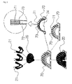
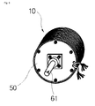
- FIG. 1 is a view showing a segmented armature motor according to an embodiment of the present invention.
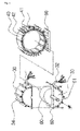
- FIGS. 2 to 4 are perspective views showing a process of assembling the segmented armature motor according to the embodiment of the present invention.
- FIG. 5 is a cross-sectional view showing a rotor constituting the segmented armature motor according to the embodiment of the present invention.
- a segmented armature motor 10 includes a plurality of armature coils 20 enclosing a rotor 60 having a rotary shaft 61, an armature 30 housing the armature coils 20 and coupled in a segmented form, a motor frame 40 coupled with the armature 30 so as to enclose the armature 30, motor covers 50 coupled to front and rear faces of the motor frame 40, and a coil frame 70 mounted between the armature coils 20 and the rotor 60.
- Each armature coil 20 is formed in a hollow shape, is bent from one or opposite ends of an intermediate portion thereof, and is provided with armature coil terminals 21 on one side thereof.
- each armature coil 20 is formed in a hollow shape such as a horseshoe shape or a U shape, and has armature coil terminals 21 mounted on one side thereof.
- each armature coil 20 is shaped so as to enclose the coil frame 70 to be described below, and is formed in a double horseshoe or U shape by bending a circular or quadrangular coil on opposite sides thereof at constant intervals.
- Each armature coil is installed so as to enclose an outer circumference and opposite sides of the rotor in three directions.
- the armature coils 20 are installed in units of a multiple of 3, and are distinguished into front and rear portions in an order in which each is in contact with the rotor 60.
- the armature coils 20 are coupled as unit coils, and the armature coil terminals 21 are formed on each armature coil, and are connected based on an armature circuit configuration.
- the coil frame 70 mounted between the armature coils 20 and the rotor 60 is segmented, and is provided with an internal space 74 so as to house the rotor 60.
- the coil frame 70 is formed in two so as to be easily assembled. Flanges of the segmented coil frames are formed so as to be easily coupled and positioned in such a way that one thereof is formed with coupling holes and that the other is formed with coupling protrusions.
- An outer surface of the coil frame 70 is provided with coil frame partitions 71, each of which has support slots 72 at intervals and a coil frame support wall 73 slantingly formed on one or opposite sides thereof.
- each armature coil 20 is fixed using the support slots 72 and the support wall(s) 73 of each coil frame partition 71.
- An outer surface of the armature frame 31 is provided with armature frame fixtures 34 protruding at intervals.
- the armature frame 31 houses the armature coils 20 and the coil frame 70, which are coupled to each other.
- the armature frame 31 is configured so that frame supports 35 protruding from an inner surface thereof are fixedly inserted into the coil frame partitions 71 constituting the coil frame 70. Then, the armature covers 33 are coupled to the armature frame 31.
- the other armature frame 31 is fixedly coupled in the process above.
- the armature covers 33 are each provided with an extension 36 so as to be able to prevent the armature coils 20 from being exposed.
- a dielectric sheet 80 is mounted between the coil frame 70 and the armature frame 31.
- the motor frame 40 enclosing the armature 30 is provided with motor frame cooling fins 41 protruding from an outer surface thereof at intervals for cooling the armatures, and motor frame insertion grooves 42 formed in an inner surface thereof at intervals.
- the motor frame 40 is configured so that the armature 30 of the rotor 60 is inserted into the motor frame insertion grooves 42 formed in the inner surface thereof.
- the motor frame 40 may be selectively provided with a pedestal 90 on the outer surface thereof so as to be able to stably support the motor frame 40.
- Motor covers 50 coupled to front and rear faces of the motor frame 40 are formed in a shape corresponding to that of the motor frame 40.
- Bearings 51 are mounted on portions of the motor covers 50 through which the rotary shaft 61 of the rotor 60 passes.
- the motor covers 50 are bolted to the motor frame 40.
- the motor covers 50 are coupled to the motor frame 40 to which the armature coils 20, the coil frame 70, the armature 30, and the rotor 60 are coupled.
- the rotor 60 mounted in the coil frame 70 is formed of a non-magnetic conductor, and is provided with a rotor hole 63 for the rotary shaft 61 in the inner center thereof.
- An inner cylinder 64 of the rotor can be reduced in density by a slimming process, and an outer cylinder 65 of the rotor is provided with magnet holes 66 into which permanent magnets 62 can be inserted.
- the permanent magnets 62 are configured so that N and S poles thereof are disposed in a rotating direction of the rotor, and so that the neighboring ones thereof are disposed so as to have repulsive poles, i.e. the same poles.
- each permanent magnet 62 a laminated permanent magnet of flat magnets or a monolithic permanent magnet is used.
- FIG. 6 shows a segmented armature motor 10 according to another embodiment of the present invention.
- the segmented armature motor 10 is configured so that permanent magnets 62 are fixed so as to be able to rotate along with each rotor 60 to which a rotary shaft 61 is fixed, so that an armature frame 31 is fitted to a coil frame 70 with armature coils 20 installed and is covered with armature covers 33, and so that a filler 100 is inserted into a space between the armature frame and each armature cover and fixes the armature coils 20.
- a motor frame 40 In a state in which segmented armatures 30 are engaged with each other, a motor frame 40 is fixed using fixing bolts.
- the rotary shaft 61 is coupled inside the armature 30, and the rotor 60 equipped with the permanent magnets 62 is rotatably installed.
- motor covers 50 having bearings 51 are fixed to the motor frame 40 using assembling bolts. It is shown that a plurality of motor drivers are installed in one motor frame 40.
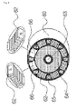
- FIGS. 7 to 10 show a segmented armature motor according to yet another embodiment of the present invention.
- the segmented armature motor 10 includes a plurality of armature coils 20, an armature 30 housing the armature coils 20 and coupled in a segmented form, a motor frame 40 coupled with the armature 30 so as to enclose the armature 30, and motor covers 50 coupled to front and rear faces of the motor frame 40.
- the armature 30 is integrally formed with a coil frame 70.
- Each armature coil 20 is configured to be bent in a horseshoe or U shape at predetermined intervals and to enclose the rotor 60, and is installed on the coil frame 70 so as to be the segmented armatures 30.
- the rotor 60 to which the rotary shaft 61 is coupled is inserted inside the segmented coil frames 70.
- the coil frames coupled with the rotor 60 are coupled with the motor frame 40.
- the motor frame 40 is segmented into two parts which are inserted at opposite sides of the rotary shaft 61.
- Each part of the motor frame 40 is configured to have coil recesses 141 into which the armature coils 20 are inserted so as to be in close contact according to a shape of each armature 30, first protrusions 142 fitted into circumferential spaces of the armature coils 20, and second protrusions 143 inserted into lateral spaces of the armature coils 20.
- the coil recesses 141, the first protrusions 142, and the second protrusions 143 of the motor frame 40 may be formed by laminating a plurality of iron core sheets.
- the coil frame 70 is formed in two so as to have the internal space 74 formed therein and the coil frame partitions 71 formed on the outer surface thereof.
- Each of the coil frame partitions 71 has the support slots 72 formed at intervals and the coil frame support wall 73 slantingly formed on one or opposite sides thereof.
- the armature coils 20 are mounted between the coil frame partitions 71.
- Each armature coil 20 is formed in a hollow shape such as a horseshoe or U shape, and is mounted with the armature coil terminals 21 on one side thereof.
- the rotor 60 which is formed of a non-magnetic conductor and has the rotary shaft 61 mounted in the inner center thereof and the magnet holes 66 formed in the outer cylinder 65 thereof so that the permanent magnets 62 can be inserted, is mounted in the internal space 74 of one coil frame 70, and then the coil frames 70 are coupled.
- the armature 30 is formed so as to have the armature frame 31 equipped with the armature cable 32, the armature covers 33 coupled to the front and rear faces of the armature frame 31, the armature frame fixtures 34 protruding from the outer surface of the armature frame 31 at intervals, and the frame supports 35 protruding from the inner surface of the armature frame 31 at intervals, and then an assembly of the armature coil 20, the rotor 60, and the coil frame 70 is mounted in the armature 30.
- the armature frame 31 houses the armature coils 20 and the coil frame 70, which are coupled to each other.
- the armature frame 31 is configured so that the frame supports 35 protruding from the inner surface thereof are fixedly inserted into the coil frame partitions 71 constituting the coil frame 70. Then, the armature covers 33 are coupled to the armature frame 31.
- the other armature frame 31 is fixedly coupled in the process above.
- the armature 30 is inserted into the motor frame 40 that has the motor frame cooling fins 41 protruding from the outer surface thereof at intervals for cooling the armatures and the motor frame insertion grooves 42 formed in the inner surface thereof at intervals.
- the motor covers 50 are mounted in the front and rear of the motor frame 40. Thereby, the process of assembling the segmented armature motor 10 is completed.
- the assembly sequence of the segmented armature motor 10 may be different from the aforementioned sequence.
- segmented armature motor of the present invention has been described on the basis of a specific shape and direction with reference to the attached drawings, it will be appreciated by those skilled in the art that various modifications, additions, and substitutions are possible and should be interpreted to fall into the scope and spirit of the present invention as disclosed in the accompanying claims.
Landscapes
- Engineering & Computer Science (AREA)
- Power Engineering (AREA)
- Iron Core Of Rotating Electric Machines (AREA)
- Permanent Magnet Type Synchronous Machine (AREA)
- Motor Or Generator Frames (AREA)
- Insulation, Fastening Of Motor, Generator Windings (AREA)
- Permanent Field Magnets Of Synchronous Machinery (AREA)
- Manufacture Of Motors, Generators (AREA)
Applications Claiming Priority (2)
| Application Number | Priority Date | Filing Date | Title |
|---|---|---|---|
| KR20100072357 | 2010-07-27 | ||
| PCT/KR2011/005483 WO2012015209A2 (ko) | 2010-07-27 | 2011-07-26 | 분할형 전기자 형태의 전동기 |
Publications (1)
| Publication Number | Publication Date |
|---|---|
| EP2600501A2 true EP2600501A2 (de) | 2013-06-05 |
Family
ID=45530584
Family Applications (1)
| Application Number | Title | Priority Date | Filing Date |
|---|---|---|---|
| EP11812739.8A Withdrawn EP2600501A2 (de) | 2010-07-27 | 2011-07-26 | Motor mit segmentiertem anker |
Country Status (10)
| Country | Link |
|---|---|
| US (1) | US9484780B2 (de) |
| EP (1) | EP2600501A2 (de) |
| JP (1) | JP5768315B2 (de) |
| KR (1) | KR101218945B1 (de) |
| CN (1) | CN103026588B (de) |
| IN (1) | IN2013MN00310A (de) |
| MX (1) | MX2013001081A (de) |
| PH (1) | PH12013500148A1 (de) |
| RU (1) | RU2550506C2 (de) |
| WO (1) | WO2012015209A2 (de) |
Families Citing this family (4)
| Publication number | Priority date | Publication date | Assignee | Title |
|---|---|---|---|---|
| GB2549694A (en) * | 2016-04-04 | 2017-11-01 | Vastech Holdings Ltd | Electric motor |
| US10256688B1 (en) * | 2017-10-10 | 2019-04-09 | Zero E Technologies, Llc | Electric machine rotor cooling systems and methods |
| RU2685420C1 (ru) * | 2017-12-20 | 2019-04-18 | федеральное государственное бюджетное образовательное учреждение высшего образования "Уфимский государственный авиационный технический университет" | Магнитопровод статора электромеханических преобразователей энергии |
| US11646622B2 (en) * | 2021-01-21 | 2023-05-09 | Beta Air, Llc | Methods and systems for a stator with helical windings configured for use in electric aircraft motor |
Family Cites Families (27)
| Publication number | Priority date | Publication date | Assignee | Title |
|---|---|---|---|---|
| US3191081A (en) * | 1961-04-13 | 1965-06-22 | Faulhaber Fritz | Permanent magnet miniature motor |
| US3209187A (en) * | 1961-05-12 | 1965-09-28 | Angele Wilhelm | Printed armature device |
| DE1463855B2 (de) * | 1964-02-27 | 1970-12-23 | Retobobina Handelsanstalt, Schaan (Liechtenstein) | Verfahren zur Herstellung einer Ankerwicklung für elektrische Maschinen, insbesondere kleine Gleichstrommaschinen |
| US4103196A (en) * | 1975-09-19 | 1978-07-25 | Matsushita Electric Works, Ltd. | Coreless motor |
| JPS6037686B2 (ja) * | 1976-06-30 | 1985-08-28 | 松下電工株式会社 | 整流子モ−タ−のロ−タ− |
| US4556811A (en) * | 1980-01-10 | 1985-12-03 | Electric Indicator Company, Inc. | Coil unit and coil form for electrical machines |
| SU1138895A1 (ru) * | 1982-04-02 | 1985-02-07 | Краматорский Индустриальный Институт | Электрическа машина преимущественно посто нного тока |
| JPS58207834A (ja) * | 1982-05-26 | 1983-12-03 | Matsushita Electric Ind Co Ltd | 電動機の固定子鉄心 |
| US4968911A (en) * | 1985-11-20 | 1990-11-06 | Allied-Signal Inc. | Clam-shell stator construction for electrical machines |
| US5798591A (en) * | 1993-07-19 | 1998-08-25 | T-Flux Pty Limited | Electromagnetic machine with permanent magnet rotor |
| US5767596A (en) * | 1996-10-03 | 1998-06-16 | General Electric Company | Dynamoelectric machine and processes for making the same |
| ES2196221T3 (es) | 1997-08-05 | 2003-12-16 | Sony Int Europe Gmbh | Circuito para deshacer la correlacion de qam. |
| KR19990023364U (ko) * | 1997-12-05 | 1999-07-05 | 추호석 | 동기형 ac서보모터의 스테이터 코아 고정장치 |
| US6812609B2 (en) * | 1998-10-21 | 2004-11-02 | Werner Anwander | Electric machine having electric coils and permanent magnets |
| DE19848503A1 (de) | 1998-10-21 | 2000-04-27 | Werner Anwander | Elektrische Maschine |
| US7211919B2 (en) * | 1999-08-16 | 2007-05-01 | American Superconductor Corporation | Thermally-conductive stator support structure |
| US6351052B1 (en) * | 2000-07-07 | 2002-02-26 | Ja Hwa Electronics Co., Ltd. | Method of winding armature coil and coreless motor produced through such method |
| JP2003264947A (ja) * | 2002-03-08 | 2003-09-19 | Fujitsu General Ltd | 永久磁石電動機 |
| JP2004120932A (ja) * | 2002-09-27 | 2004-04-15 | Matsushita Electric Ind Co Ltd | モータおよびディスク装置 |
| JP3790214B2 (ja) * | 2002-12-17 | 2006-06-28 | 株式会社 アサバ | コアレスモータ |
| JP4389918B2 (ja) * | 2006-09-28 | 2009-12-24 | 株式会社日立製作所 | 回転電機及び交流発電機 |
| JP2008199691A (ja) * | 2007-02-08 | 2008-08-28 | Liu Te En | 動力変換装置の駆動方法 |
| US7755244B2 (en) * | 2007-05-11 | 2010-07-13 | Uqm Technologies, Inc. | Stator for permanent magnet electric motor using soft magnetic composites |
| KR20090003577A (ko) * | 2007-07-03 | 2009-01-12 | 송길봉 | 회전형 철심 유도기 |
| KR100975326B1 (ko) * | 2008-07-14 | 2010-08-12 | 장석호 | 분할 코일부를 갖는 회전원반과 분할 자석체를 갖는고정판에 의한 발전장치 |
| CN101373909B (zh) * | 2008-08-26 | 2011-04-20 | 珠海格力电器股份有限公司 | 绕线骨架、电机及电机定子的绕线方法 |
| US8084909B2 (en) * | 2009-04-09 | 2011-12-27 | Goodzeit Carl L | Dual armature motor/generator with flux linkage |
-
2011
- 2011-07-26 MX MX2013001081A patent/MX2013001081A/es active IP Right Grant
- 2011-07-26 US US13/811,747 patent/US9484780B2/en not_active Expired - Fee Related
- 2011-07-26 CN CN201180036469.5A patent/CN103026588B/zh not_active Expired - Fee Related
- 2011-07-26 WO PCT/KR2011/005483 patent/WO2012015209A2/ko not_active Ceased
- 2011-07-26 PH PH1/2013/500148A patent/PH12013500148A1/en unknown
- 2011-07-26 RU RU2013108437/07A patent/RU2550506C2/ru not_active IP Right Cessation
- 2011-07-26 EP EP11812739.8A patent/EP2600501A2/de not_active Withdrawn
- 2011-07-26 JP JP2013521704A patent/JP5768315B2/ja not_active Expired - Fee Related
- 2011-07-27 KR KR1020110074365A patent/KR101218945B1/ko not_active Expired - Fee Related
-
2013
- 2013-02-14 IN IN310MUN2013 patent/IN2013MN00310A/en unknown
Non-Patent Citations (1)
| Title |
|---|
| See references of WO2012015209A2 * |
Also Published As
| Publication number | Publication date |
|---|---|
| WO2012015209A2 (ko) | 2012-02-02 |
| KR101218945B1 (ko) | 2013-01-04 |
| JP2013537793A (ja) | 2013-10-03 |
| US9484780B2 (en) | 2016-11-01 |
| KR20120010993A (ko) | 2012-02-06 |
| WO2012015209A3 (ko) | 2012-05-03 |
| PH12013500148A1 (en) | 2013-03-11 |
| IN2013MN00310A (de) | 2015-05-29 |
| US20130119815A1 (en) | 2013-05-16 |
| MX2013001081A (es) | 2013-08-21 |
| JP5768315B2 (ja) | 2015-08-26 |
| CN103026588B (zh) | 2016-04-06 |
| RU2013108437A (ru) | 2014-09-10 |
| RU2550506C2 (ru) | 2015-05-10 |
| CN103026588A (zh) | 2013-04-03 |
Similar Documents
| Publication | Publication Date | Title |
|---|---|---|
| MX2013005413A (es) | Analogos de dipeptidos para el tratamiento de afecciones asociadas con la formacion de fibrillas amiloides. | |
| US9018816B2 (en) | Rotor of motor having interpole magnets in holding member | |
| EP3120439B1 (de) | Strömungsmaschine | |
| JP5743409B2 (ja) | 電気モータ | |
| US12132353B2 (en) | Rotor, synchronous reluctance motor, and rotor forming method | |
| US20220255386A1 (en) | Coil, stator, and motor | |
| US20140021809A1 (en) | Reluctance motor | |
| US20180366997A1 (en) | Stator assembly | |
| US20170133894A1 (en) | Stator and BLDC Motor Having the Same | |
| JPWO2022019074A5 (de) | ||
| KR20090038113A (ko) | 전동기 | |
| US9484780B2 (en) | Segmented armature motor having a segmented coil frame having coil windings on the outer surface | |
| US20060071576A1 (en) | Flat board type brushless dc motor | |
| US20080136287A1 (en) | Motor | |
| KR20110058057A (ko) | 영구자석형 전동기 | |
| KR20130035707A (ko) | 스위치드 릴럭턴스 모터 | |
| JP2006296033A (ja) | ブラシレスモータ | |
| KR102541176B1 (ko) | 모터 | |
| JP2005094959A (ja) | 永久磁石式回転電機 | |
| KR20120023349A (ko) | 분할형 전기자 형태의 전동기 | |
| CN119030189B (zh) | 定子组件及其安装方法、步进电机 | |
| KR102574791B1 (ko) | 오버행 자로 단축 구조를 갖는 회전자 및 그를 포함하는 영구자석 전동기 | |
| CN112688519B (zh) | 一种定子永磁型轴向磁场永磁电机 | |
| KR20100109693A (ko) | Ipm 타입 모터 | |
| WO2024018819A1 (ja) | モータ及び天井扇 |
Legal Events
| Date | Code | Title | Description |
|---|---|---|---|
| PUAI | Public reference made under article 153(3) epc to a published international application that has entered the european phase |
Free format text: ORIGINAL CODE: 0009012 |
|
| 17P | Request for examination filed |
Effective date: 20130226 |
|
| AK | Designated contracting states |
Kind code of ref document: A2 Designated state(s): AL AT BE BG CH CY CZ DE DK EE ES FI FR GB GR HR HU IE IS IT LI LT LU LV MC MK MT NL NO PL PT RO RS SE SI SK SM TR |
|
| DAX | Request for extension of the european patent (deleted) | ||
| STAA | Information on the status of an ep patent application or granted ep patent |
Free format text: STATUS: REQUEST FOR EXAMINATION WAS MADE |
|
| STAA | Information on the status of an ep patent application or granted ep patent |
Free format text: STATUS: THE APPLICATION IS DEEMED TO BE WITHDRAWN |
|
| 18D | Application deemed to be withdrawn |
Effective date: 20180201 |