EP2600566B1 - Steuerverfahren zum blockieren unerwünschter zugriffe - Google Patents
Steuerverfahren zum blockieren unerwünschter zugriffe Download PDFInfo
- Publication number
- EP2600566B1 EP2600566B1 EP11812105.2A EP11812105A EP2600566B1 EP 2600566 B1 EP2600566 B1 EP 2600566B1 EP 11812105 A EP11812105 A EP 11812105A EP 2600566 B1 EP2600566 B1 EP 2600566B1
- Authority
- EP
- European Patent Office
- Prior art keywords
- layer
- port
- switches
- mapping table
- target apparatus
- Prior art date
- Legal status (The legal status is an assumption and is not a legal conclusion. Google has not performed a legal analysis and makes no representation as to the accuracy of the status listed.)
- Active
Links
Images


Classifications
-
- H—ELECTRICITY
- H04—ELECTRIC COMMUNICATION TECHNIQUE
- H04L—TRANSMISSION OF DIGITAL INFORMATION, e.g. TELEGRAPHIC COMMUNICATION
- H04L63/00—Network architectures or network communication protocols for network security
- H04L63/10—Network architectures or network communication protocols for network security for controlling access to devices or network resources
-
- H—ELECTRICITY
- H04—ELECTRIC COMMUNICATION TECHNIQUE
- H04L—TRANSMISSION OF DIGITAL INFORMATION, e.g. TELEGRAPHIC COMMUNICATION
- H04L12/00—Data switching networks
- H04L12/28—Data switching networks characterised by path configuration, e.g. LAN [Local Area Networks] or WAN [Wide Area Networks]
- H04L12/46—Interconnection of networks
- H04L12/4604—LAN interconnection over a backbone network, e.g. Internet, Frame Relay
- H04L12/462—LAN interconnection over a bridge based backbone
-
- H—ELECTRICITY
- H04—ELECTRIC COMMUNICATION TECHNIQUE
- H04L—TRANSMISSION OF DIGITAL INFORMATION, e.g. TELEGRAPHIC COMMUNICATION
- H04L63/00—Network architectures or network communication protocols for network security
- H04L63/10—Network architectures or network communication protocols for network security for controlling access to devices or network resources
- H04L63/101—Access control lists [ACL]
-
- H—ELECTRICITY
- H04—ELECTRIC COMMUNICATION TECHNIQUE
- H04L—TRANSMISSION OF DIGITAL INFORMATION, e.g. TELEGRAPHIC COMMUNICATION
- H04L63/00—Network architectures or network communication protocols for network security
- H04L63/14—Network architectures or network communication protocols for network security for detecting or protecting against malicious traffic
- H04L63/1441—Countermeasures against malicious traffic
-
- H—ELECTRICITY
- H04—ELECTRIC COMMUNICATION TECHNIQUE
- H04L—TRANSMISSION OF DIGITAL INFORMATION, e.g. TELEGRAPHIC COMMUNICATION
- H04L61/00—Network arrangements, protocols or services for addressing or naming
- H04L61/09—Mapping addresses
- H04L61/10—Mapping addresses of different types
- H04L61/103—Mapping addresses of different types across network layers, e.g. resolution of network layer into physical layer addresses or address resolution protocol [ARP]
Definitions
- the present invention relates to a method and a program for controlling communication of a target apparatus based on port information of one or more Layer-2 switches connected to communication apparatuses in a network.
- Patent document 1 discloses an access control apparatus, which blocks the communication by transmitting false ARP(Address Resolution Protocol) response packet if the communication between nodes that are not permitted according to the access policy is detected. Especially the access control apparatus controls "permitted” or “not permitted” communication between nodes independent of hardware or software even when the ARP-table of the unauthorized node has been configured statically.
- ARP Address Resolution Protocol
- Patent document 2 discloses a system for preventing illegal connections, which prevents connections to private servers and other nodes in the same subnet from an unauthorized node not permitted based on an approval list and prevent connections to the external network via routers etc from the unauthorized node based on the approval list, by registering the MAC addresses of nodes permitted to access the network to the approval list and transmitting ARP packets with a false MAC-address to the unauthorized node.
- Patent document 3 discloses an apparatus for preventing illegal connections, which prevents unauthorized network access by transmitting ARP-request packets successively to all registered nodes, judging whether the profile of the node has been already registered based on the ARP-reply packet received from the node in response to the ARP-request packet, and transmitting disturb-messages which shows that the node includes multiple profiles in a case where it is judged that the node has not been registered.
- Patent document 4" discloses networkmap creating method, which detects the inter connections of the OSI Reference Model Layer-2 switches (inter-switch connections) and the connections of computers to the OSI Reference Model Layer-2 switches (switch-terminal connections) in the network in which there are one or more OSI Reference Model layer-2 switches using a new algorithm.
- the new algorithm shows the method of generating MvP table as mapping table with MAC address and port information of Layer-2 switches based on port information of Layer-2 switches collected by network monitoring manager and detecting connections of Layer-2 switches and connections of computers to the Layer-2 switches in the network.
- the inventor of this invention is "Keeni, Glenn Mansfield” that is the same as the inventor in the present application.
- the assignee of this invention is "CYBER SOLUTIONS INC.” that is the same as the assignee in the present application.
- Patent documents 1-3 comprise unsolvable problems shown below.
- Layer-2 switch as one of the apparatus which relays packets in network judges the forwarding address using the destination MAC address contained in a packet. Therefore, it is apositivemethodto detect the Layer-2 switch port connected to the target apparatus and to disable the Layer-2 switch port connected to the target apparatus in order to block communication of the target apparatus with multiple IP addresses immediately and certainly.
- the present invention proposes a method and a program for detecting the Layer-2 switch port connected to the target apparatuses in network using the MvP table described in patent document 4, and blocking the communication of the target apparatus by administratively disabling the Layer-2 switch port connected to the said target apparatus.
- the present invention provides the method and the program for controlling communication of the target apparatus, specifically, blocking the communication of the target apparatus immediately and certainly in case where illegal connection to the target apparatus is detected in the network arranged one or more Layer-2 switches, and unblocking the communication of the target apparatus in case where the communication of the Layer-2 switch port connected to the said target apparatus has been blocked.
- the problem is solved by the features of claims 1 respectively 4. Further, specific problems are solved by the subclaims.
- the invention described in Claim 1 is a method for blocking communication of a target apparatus based on port information of one or more Layer-2 switches connected to communication apparatuses in a network, comprising of:
- the invention described in Claim 2 is the method according to Claim 1, wherein the third step comprises of:
- the invention described in Claim 3 is the method according to Claim 1-2, further comprising of:
- the invention described in Claim 4 is a computer program embodied on a non-transitory computer readable medium of network monitoring manager to execute processes for blocking communication of a target apparatus based on port information of one or more Layer-2 switches connected to communication apparatuses in a network, comprising of:
- the invention described in Claim 5 is the computer program according to Claim 4, wherein the third executable process comprises of:
- the invention described in Claim 6 is the computer program according to Claim 4-5, further comprising of:
- the invention described in Claim 1 or Claim 4 produces the effect of being able to carry out detecting automatically the Layer-2 switches ports connected to communication apparatuses, and being able to carry out blocking communication of the target apparatus immediately and certainly by administratively disabling the Layer-2 switch port connected to the target apparatus in case where illegal connection to the target apparatus is detected in the network. Therefore, the invention produces the effect of improving operational efficiency of network management, and being able to strengthen security in the network.
- the invention described in Claim 2 or Claim 5 produces the effect of being able to carry out detecting easily the Layer-2 switches ports connected to communication apparatuses in the network.
- the invention described in Claim 3 or Claim 6 produces the effect of being able to carry out unblocking the communication of the target apparatus immediately and certainly by administratively enabling the Layer-2 switch port connected to the target apparatus, for example, after an investigation into the cause of the illegal connection to the target apparatus is completed and an appropriate treatment according to the investigation result is completed, in case where the Layer-2 switch port connected to the target apparatus has been disabled.
- Figure 1 shows an example of the network configuration of the present invention, proposing the method and the program for controlling the communication of the target apparatus, specifically, blocking and unblocking the communication of the target apparatus.
- network monitoring manager H in which SNMP (Simple Network Management Protocol) manager is implemented, Layer-2 switches S1, S2, S3 in which SNMP agent is implemented, communication apparatus C1 connected to Layer-2 switch S1, communication apparatuses C2, C3 connected to Layer-2 switch S2, communication apparatuses C4,C5,C6 connected to Layer-2 switch S3 exist in the network.
- nth port of Layer-2 switches Sj (1 ⁇ j ⁇ 3) is described as P(Sj,n) (1 ⁇ n ⁇ total number of port of Layer-2 switches Sj).
- the port P(S1,15) of Layer-2 switch S1 is connected to the port P(S2,1) of Layer-2 switch S2.
- the port P (S2, 14) of Layer-2 switch S2 is connected to the port P (S3, 1) of Layer-2 switch S3.
- the network monitoring manager H carries out blocking communication of the target apparatus Ci immediately and certainly by detecting automatically the Layer-2 switch port connected to the communication apparatus Ci, that is identified as the target apparatus including illegal connection, based on the MvP table, and blocking the communication of the target apparatus Ci by administratively disabling the Layer-2 switch port connected to the target apparatus Ci, in case where the network monitoring manager H detects illegal connection to the communication apparatus Ci in the network.
- the network monitoring manager H detects the following illegal connections to the communication apparatus Ci, and identifies the communication apparatus Ci as the target apparatus.
- the network monitoring manager H carries out blocking the communication of the target apparatus Ci immediately and certainly by identifying the communication apparatus Ci including illegal connection as the target apparatus, detecting the Layer-2 switch port connected to the target apparatus Ci based on the MvP table, and blocking the communication of the target apparatus Ci by administratively disabling the Layer-2 switch port connected to the target apparatus Ci.
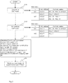
- Figure 2 shows an example of blocking the communication of the target apparatus C4 in case where the network monitoring manager H detects the illegal connection to the communication apparatus C4, and identifies the communication apparatus C4 as the target apparatus.
- step S01 the MvP table consisting of the mapping table M1 and the mapping table M2 based on management information collected from Layer-2 switches Sj by the network monitoring manager H is generated, wherein the mapping table M1 provides a mapping between MAC address M(C4) of the communication apparatus C4 and port information set Row ⁇ M(C4) ⁇ of Layer-2 switches Sj (1 ⁇ j ⁇ 3) that detected the said MAC address M (C4), and the mapping table M2 provides a mapping between MAC address M(Sj) of Layer-2 switches Sj and port information set Row ⁇ M(Sj) ⁇ of Layer-2 switches Sj that detected the said MAC address M(Sj).
- the network monitoring manager H collects the port information of Layer-2 switch Sj by making a request with IP address to Layer-2 switch Sj in which SNMP agent is implemented, receiving SNMP management information (MIB1 specified in RFC1156, MIB2 specified in RFC1213, and IF-MIB specified in RFC2863) from Layer-2 switch Sj, and detecting MAC address included in header of packets that have passed through arbitrary ports P (Sj , n) of Layer-2 switch Sj based on the SNMP management information.
- MIB1 specified in RFC1156, MIB2 specified in RFC1213, and IF-MIB specified in RFC2863
- the network monitoring manager H makes a request with IP address to all elements whose IP address is stored in the network monitoring manager H, receives SNMP management information from the elements in which SNMP agent is implemented, and detects the IP address of Layer-2 switch Sj based on the SNMP management information.
- step S02 in case where the same port information is seen in both the port information set Row ⁇ M (C4) ⁇ of the mapping table M1 and the port information set Row ⁇ M(Sj) ⁇ of the mapping table M2,the MvP table is normalized by deleting elements of ports P(Sj,n) corresponding to said port information from the port information set Row ⁇ M(Sj) ⁇ of the mapping table M2.
- step S02 normalizing process is performed as follows. Anything is not deleted from the port information set Row ⁇ M(S1) ⁇ of the mapping table M2, because the same port information is not seen in both the port information set Row ⁇ M(C4) ⁇ of the mapping table M1 and the port information set Row ⁇ M(S1) ⁇ of the mapping table M2.
- the element of port P(S1,15) is deleted from the port information set Row ⁇ M(S2) ⁇ of the mapping table M2, because the element of the same port P(S1,15) is seen in both the port information set Row ⁇ M(C4) ⁇ of the mapping table M1 and the port information set Row ⁇ M(S2) ⁇ of the mapping table M2.
- the elements of port P(S1,15) and P(S2,14) are deleted from the port information set Row ⁇ M(S3) ⁇ of the mapping table M2, because the elements of the same port P(S1,15) and P(S2,14) are seen in both the port information set Row ⁇ M(C4) ⁇ of the mapping table M1 and the port information set Row ⁇ M(S3) ⁇ of the mapping table M2.
- the port information set Row ⁇ M(S3) ⁇ of the mapping table M2 is empty by normalizing process described above.
- step S03 the Layer-2 switch S3 is identified as the Layer-2 switch connected to the communication apparatus C4 because the port information set Row ⁇ M(S3) ⁇ of the mapping table M2 is empty. Also, the port P(S3,2) is identified as the port connected to the communication apparatus C4 because the element of port P(S3,2) corresponding to the port information of the Layer-2 switches S3 identified above is seen in the port information set Row ⁇ M(C4) ⁇ of the mapping table M1.
- step S04 the port P(S3,2) identified in step S03 is changed into disable state by administratively disabling the Layer-2 switch port P (S3, 2) connected to the communication apparatus C4.
- the network monitoring manager H executes the command for disabling the Layer-2 switch port P(S3,2). Thereby the communication of the communication apparatus C4 is blocked.
- the method and the program for carrying out "Execution Example 1" of the present invention is able to carry out detecting automatically the port information of Layer-2 switch connected to the communication apparatus that is identified as the target apparatus including illegal connection, and to carry out blocking communication of the target apparatus immediately and certainly by executing the step S01-S04 described above in case where illegal connection to the communication apparatus is detected in the network.
- the communication blocked state of the target apparatus that has been changed by executing the step S01-S04 described above must be removed.
- the blocked state of the target apparatus is removed by executing the step S05 instead of S04, wherein the command for disabling the Layer-2 switch port is executed in the step S05.
- Figure 3 shows an example of network configuration of the present invention, proposing the method and the program for controlling the communication of the target apparatus, specifically, blocking and unblocking the communication of the target apparatus, in case where a non-intelligent Hub that is not corresponding to SNMP exists in the network.
- the port P (S1, 15) of Layer-2 switch S1 is connected to the port P(SX,1) of non-intelligent Hub SX.
- the port P(SX,16) of non-intelligent Hub SX is connected to the port P (S2, 1) of Layer-2 switch S2.
- the port P (SX, 14) of non-intelligent Hub SX is connected to the port P(S3,1) of Layer-2 switch S3.
- Figure 4 shows an example of blocking the communication of the target apparatus C4 in case where the network monitoring manager H detects the illegal connection to the communication apparatus C4, and identifies the communication apparatus C4 as the target apparatus.
- step S01 MvP table consisting of the mapping table M1 and the mapping table M2 based on management information collected from Layer-2 switches Sj by the network monitoring manager H is generated.
- a mapping table of non-intelligent Hub SX is not generated in the MvP table because the network monitoring manager H cannot receive management information from non-intelligent Hub SX in which SNMP agent is not implemented.
- step S02 in case where the same port information is seen in both the port information set Row ⁇ M(C4) ⁇ of the mapping table M1 and the port information set Row ⁇ M(Sj) ⁇ of the mapping table M2, the MvP table is normalized by deleting elements P(Sj,n) corresponding to the said port information from the port information set Row ⁇ M(Sj) ⁇ of the mapping table M2.
- step S02 normalizing process is performed as follows.
- the element of port P (S2, 1) is deleted from the port information set Row ⁇ M(S1) ⁇ of the mapping table M2, because the element of the same port P(S2,1) is seen in both the port information set Row ⁇ M(C4) ⁇ of the mapping table M1 and the port information set Row ⁇ M(S1) ⁇ of the mapping table M2.
- the element of port P(S1,15) is deleted from the port information set Row ⁇ M(S2) ⁇ of the mapping table M2, because the element of the same port information P(S1,15) is seen in both the port information set Row ⁇ M(C4) ⁇ of the mapping table M1 and the port information set Row ⁇ M(S2) ⁇ of the mapping table M2.
- port P(S1,15) and P(S2,1) are deleted from the port information set Row ⁇ M(S3) ⁇ of the mapping table M2, because the elements of the same port P(S1,15) and P(S2,1) are seen in both the port information set Row ⁇ M(C4) ⁇ of the mapping table M1 and the port information set Row ⁇ M(S3) ⁇ of the mapping table M2.
- the port information set Row ⁇ M(S3) ⁇ of the mapping table M2 is empty by normalizing process described above.
- step S03 the Layer-2 switch S3 is identified as the Layer-2 switch connected to the communication apparatus C4 because the port information set Row ⁇ M(S3) ⁇ of the mapping table M2 is empty. Also, the port P(S3,2) is identified as the port connected to the communication apparatus C4 because the element of port P(S3,2) corresponding to the port information of the Layer-2 switches S3 identified above is seen in the port information set Row ⁇ M(C4) ⁇ of the mapping table M1.
- step S04 the port P(S3,2) identified in step S03 is changed into disable state by administratively disabling the Layer-2 switch port P (S3, 2) connected to the communication apparatus C4.
- the network monitoring manager H executes the command for disabling the Layer-2 switch port P (S3, 2) . Thereby communication of the communication apparatus C4 is blocked.
- the method and the program for carrying out "Execution Example 2" of the present invention is able to carry out detecting automatically the port information of Layer-2 switch connected to the communication apparatus that is identified as the target apparatus including illegal connection, and to carry out blocking communication of the target apparatus immediately and certainly by executing the step S01-S04 described above in case where illegal connection to the communication apparatus is detected in the network.
- Figure 5 shows an example of network configuration of the present invention, proposing the method and the program for controlling the communication of the target apparatus, specifically, blocking and unblocking the communication of the target apparatus, in case where a non-intelligent Hub that is not corresponding to SNMP exists in the network.
- the port P(S1,15) of Layer-2 switch S1 is connected to the port P(S2,1) of Layer-2 switch S2.
- the port P(S2,14) of Layer-2 switch S2 is connected to the port P(S3,1) of Layer-2 switch S3.
- the port P(S3,2) of Layer-2 switch S3 is connected the port P(SX,1) of non-intelligent Hub SX.
- the method and the program for carrying out "Execution Example 3" of the present invention is able to carry out detecting automatically the Layer-2 switch port P(S3,2) connected to the communication apparatus C4 that is identified as the target apparatus including illegal connections, and to carry out blocking communication of the target apparatus C4 immediately and certainly by administratively disabling the Layer-2 switch port P(S3,2).
- the communication that has passed through ports of non-intelligent Hub SX is completely blocked by administratively disabling the Layer-2 switch port P(S3,2).
- This invention is able to apply technology for immediately and certainly blocking communication of the communication apparatus in case where illegal connection to the communication apparatus is detected in the network arranged one or more Layer-2 switches.
Landscapes
- Engineering & Computer Science (AREA)
- Computer Security & Cryptography (AREA)
- Computer Networks & Wireless Communication (AREA)
- Signal Processing (AREA)
- Computer Hardware Design (AREA)
- Computing Systems (AREA)
- General Engineering & Computer Science (AREA)
- Small-Scale Networks (AREA)
Claims (6)
- (Aktuell geändert) Verfahren zum Blockieren der Kommunikation einer Zielvorrichtung (Ci) auf Basis von Port-Informationen eines oder mehrerer Layer-2-Switches, verbunden mit Kommunikationsvorrichtungen in einem Netzwerk, wobei das Verfahren umfasst:einen ersten Schritt zum Erzeugen einer MvP-Tabelle, bestehend aus einer ersten Mapping-Tabelle (M1) undeiner zweiten Mapping-Tabelle (M2), basierend auf Management-Informationen, die von den Layer-2-Switches durch einen Netzwerküberwachungsmanager gesammelt werden,wobei die erste Mapping-Tabelle (M1) ein Mapping zwischen MAC-Adresse M(Ci) der Zielvorrichtung (Ci), wobei 1 ≤ i ≤ Gesamtzahl der Kommunikationsvorrichtungen im Netzwerk ist,und den Port-Informationssatz Row{M(Ci)} von Layer-2-Switches (Sj)Sj umfasst, wobei 1 ≤ j ≤ Gesamtzahl der Layer-2-Switches ist, welche die MAC-Adresse M(Ci) erkannt haben, unddie zweite Mapping-Tabelle (M2) ein Mapping zwischen der MAC-Adresse M(Sj) der Layer-2-Switches (Sj) und dem Port-Informationssatz Row{M(Sj)} von Layer-2-Switches (Sj), welche die MAC-Adresse M(Sj) erkannt haben, bereitstellt;einen zweiten Schritt zum Normalisieren der MvP-Tabelle, wobei, wenn derselbe Port sowohl in dem Port-Informationssatz Row{M(Ci)} der ersten Mapping-Tabelle (M1) als auch im Port-Informationssatz Row{M(Sj)} der zweiten Mapping-Tabelle (M2) zu sehen ist, die MvP-Tabelle durch Löschen von Elementen der Ports P(Sj,n) (1 ≤ n ≤ Gesamtzahl der Ports von Layer-2-Switches (Sj)), die demselben Port entsprechen, aus dem Port-Informationssatz Row{M(Sj)} der zweiten Mapping-Tabelle (M2) normalisiert wird, undeinen dritten Schritt des Identifizierens des Layer-2-Switch-Ports, der mit der Zielvorrichtung (Ci) verbunden ist, auf Basis der im zweiten Schritt normalisierten MvP-Tabelle;dadurch gekennzeichnet, dass das Verfahren ferner umfasst:einen vierten Schritt zum Blockieren der Kommunikation der Zielvorrichtung (Ci) durch administratives Deaktivieren des Layer-2-Switch-Ports, der mit der Zielvorrichtung (Ci) verbunden ist, auf Basis des im dritten Schritt identifizierten Layer-2-Switch-Ports.
- (Aktuell geändert) Verfahren nach Anspruch 1, wobei der dritte Schritt ferner umfasst:(1) Identifizieren der Layer-2-Switches (Sj) als Layer-2-Switch, der mit der Kommunikationsvorrichtung (Ci) verbunden ist, in dem Fall, in dem der Port-Informationssatz Row{M(Sj)} der zweiten Mapping-Tabelle (M2) leer ist;(2) Identifizieren des Ports P(Sj,n) als Port, der mit der Kommunikationsvorrichtung (Ci) verbunden ist, in dem Fall, in dem das Element des Ports P(Sj,n), das dem Port der in (1) identifizierten Layer-2-Switches (Sj) entspricht, in dem Port-Informationssatz Row{M(Ci)} der ersten Mapping-Tabelle (M1) zu sehen ist.
- (Aktuell geändert) Verfahren nach Anspruch 1-2, ferner umfassend:einen fünften Schritt zur Freigabe der Kommunikation der Zielvorrichtung (Ci) durch administratives Aktivieren des Layer-2-Switch-Ports, der mit der Zielvorrichtung (Ci) verbunden ist, in dem Fall, in dem der Layer-2-Switch-Port, der mit der Zielvorrichtung (Ci) verbunden ist, deaktiviert wurde.
- (Aktuell geändert) Computerprogramm, das auf einem nicht-flüchtigen, computerlesbaren Medium eines Netzwerküberwachungsmanagers verkörpert ist, um Prozesse zum Blockieren der Kommunikation einer Zielvorrichtung auf Basis von Port-Informationen eines oder mehrerer Layer-2-Switches, verbunden mit Kommunikationsvorrichtungen in einem Netzwerk, auszuführen, bestehend aus:einem ersten ausführbaren Prozess zum Erzeugen einer MvP-Tabelle, die aus einer ersten Mapping-Tabelle (M1) und einer zweiten Mapping-Tabelle (M2) besteht, auf Basis von Management-Informationen, die von den Layer-2-Switches durch einen Netzwerküberwachungsmanager gesammelt wurden, wobei die erste Mapping-Tabelle (M1) ein Mapping zwischen der MAC-Adresse M(Ci) der Zielvorrichtung (Ci), wobei 1 ≤ i ≤ Gesamtzahl der Kommunikationsvorrichtungen im Netzwerk ist,und dem Port-Informationssatz Row{M(Ci)} von Layer-2-Switches (Si) bereitstellt, wobei 1 ≤ j ≤ Gesamtzahl von Layer-2-Switches, welche die MAC-Adresse M(Ci) erkannt haben, ist, und die zweite Mapping-Tabelle (M2) ein Mapping zwischen der MAC-Adresse M(Sj) der Layer-2-Switches (Sj) und dem Port-Informationssatz Row{M(Sj)} von Layer-2-Switches (Sj), welche die MAC-Adresse M(Sj) erkannt haben, bereitstellt;einem zweiten ausführbaren Prozess zum Normalisieren der MvP-Tabelle, wobei, wenn derselbe Port sowohl in dem Port-Informationssatz Row{M(Ci)} der ersten Mapping-Tabelle (M1) als auch im Port-Informationssatz Row{M(Sj)} der zweiten Mapping-Tabelle (M2) zu sehen ist, die MvP-Tabelle durch Löschen von Elementen der Ports P(Sj,n), wobei 1 ≤ n ≤ Gesamtzahl der Ports von Layer-2-Switches (Sj) ist, die demselben Port entsprechen, aus dem Port-Informationssatz Row{M(Sj)} der zweiten Mapping-Tabelle (M2) normalisiert wird, undeinem dritten ausführbaren Prozess zum Identifizieren des Layer-2-Switch-Ports, der mit der Zielvorrichtung (Ci) verbunden ist, auf Basis der im zweiten ausführbaren Prozess normalisierten MvP-Tabelle;dadurch gekennzeichnet, dass das Programm ferner umfasst:einen vierten ausführbaren Prozess zum Blockieren der Kommunikation der Zielvorrichtung (Ci) durch administratives Deaktivieren des Layer-2-Switch-Ports, der mit der Zielvorrichtung (Ci) verbunden ist, auf Basis des im dritten ausführbaren Prozess identifizierten Layer-2-Switch-Ports.
- (Aktuell geändert) Computerprogramm nach Anspruch 4, wobei der dritte ausführbare Prozess ferner umfasst:(1) Identifizieren der Layer-2-Switches (Sj) als Layer-2-Switch, der mit der Kommunikationsvorrichtung (Ci) verbunden ist, in dem Fall, in dem der Port-Informationssatz Row{M(Sj)} der zweiten Mapping-Tabelle (M2) leer ist;(2) Identifizieren des Ports P(Sj,n) als Port, der mit der Kommunikationsvorrichtung (Ci) verbunden ist, in dem Fall, in dem das Element des Ports P(Sj,n), das dem Port der in (1) identifizierten Layer-2-Switches (Sj) entspricht, in dem Port-Informationssatz Row{M(Ci)} der ersten Mapping-Tabelle (M1) zu sehen ist.
- (Aktuell geändert) Verfahren nach Anspruch 4-5, ferner umfassend:einen fünften ausführbaren Prozess zur Freigabe der Kommunikation der Zielvorrichtung (Ci) durch administratives Aktivieren des Layer-2-Switch-Ports, der mit der Zielvorrichtung (Ci) verbunden ist, in dem Fall, in dem der Layer-2-Switch-Port, der mit der Zielvorrichtung (Ci) verbunden ist, deaktiviert wurde.
Applications Claiming Priority (2)
| Application Number | Priority Date | Filing Date | Title |
|---|---|---|---|
| JP2010172126 | 2010-07-30 | ||
| PCT/JP2011/053489 WO2012014509A1 (ja) | 2010-07-30 | 2011-02-18 | 不正アクセス遮断制御方法 |
Publications (3)
| Publication Number | Publication Date |
|---|---|
| EP2600566A1 EP2600566A1 (de) | 2013-06-05 |
| EP2600566A4 EP2600566A4 (de) | 2016-06-08 |
| EP2600566B1 true EP2600566B1 (de) | 2017-08-02 |
Family
ID=45529733
Family Applications (1)
| Application Number | Title | Priority Date | Filing Date |
|---|---|---|---|
| EP11812105.2A Active EP2600566B1 (de) | 2010-07-30 | 2011-02-18 | Steuerverfahren zum blockieren unerwünschter zugriffe |
Country Status (4)
| Country | Link |
|---|---|
| US (1) | US8955049B2 (de) |
| EP (1) | EP2600566B1 (de) |
| JP (1) | JP5134141B2 (de) |
| WO (1) | WO2012014509A1 (de) |
Families Citing this family (10)
| Publication number | Priority date | Publication date | Assignee | Title |
|---|---|---|---|---|
| EP2600566B1 (de) * | 2010-07-30 | 2017-08-02 | Cyber Solutions Inc. | Steuerverfahren zum blockieren unerwünschter zugriffe |
| JP6127650B2 (ja) * | 2013-03-28 | 2017-05-17 | 沖電気工業株式会社 | 局番認識装置および局番認識システム |
| JP6117050B2 (ja) * | 2013-08-09 | 2017-04-19 | 株式会社日立製作所 | ネットワーク制御装置 |
| CN105699383B (zh) * | 2015-12-16 | 2018-10-16 | 南京铁道职业技术学院 | 增强消息传送能力的轨道扣件的检测方法 |
| JP2018064228A (ja) * | 2016-10-14 | 2018-04-19 | アンリツネットワークス株式会社 | パケット制御装置 |
| JP6836460B2 (ja) * | 2017-01-23 | 2021-03-03 | アラクサラネットワークス株式会社 | ネットワークシステム、ネットワーク管理サーバ、ネットワーク制御方法およびプログラム |
| US10979323B2 (en) | 2017-05-31 | 2021-04-13 | Cyber Solutions Inc. | Network map display method and network map display program |
| JP2019041176A (ja) * | 2017-08-23 | 2019-03-14 | 株式会社ソフトクリエイト | 不正接続遮断装置及び不正接続遮断方法 |
| JP6977507B2 (ja) * | 2017-11-24 | 2021-12-08 | オムロン株式会社 | 制御装置および制御システム |
| JP7738294B2 (ja) * | 2021-11-24 | 2025-09-12 | 株式会社サイバー・ソリューションズ | L2スイッチ検出方法およびプログラム |
Family Cites Families (23)
| Publication number | Priority date | Publication date | Assignee | Title |
|---|---|---|---|---|
| JP2859270B2 (ja) | 1987-06-11 | 1999-02-17 | 旭光学工業株式会社 | カメラの視線方向検出装置 |
| GB2268374A (en) * | 1992-06-23 | 1994-01-05 | Ibm | Network addressing |
| JPH079706A (ja) | 1993-06-25 | 1995-01-13 | Canon Inc | 印刷装置 |
| JPH0832607A (ja) * | 1994-07-13 | 1996-02-02 | Hitachi Cable Ltd | ネットワーク構成管理方法 |
| US5926463A (en) * | 1997-10-06 | 1999-07-20 | 3Com Corporation | Method and apparatus for viewing and managing a configuration of a computer network |
| JP4558139B2 (ja) * | 2000-05-02 | 2010-10-06 | 株式会社バッファロー | ネットワーク管理装置 |
| US7383574B2 (en) * | 2000-11-22 | 2008-06-03 | Hewlett Packard Development Company L.P. | Method and system for limiting the impact of undesirable behavior of computers on a shared data network |
| JP2004185498A (ja) | 2002-12-05 | 2004-07-02 | Matsushita Electric Ind Co Ltd | アクセス制御装置 |
| JP4174392B2 (ja) | 2003-08-28 | 2008-10-29 | 日本電気株式会社 | ネットワークへの不正接続防止システム、及びネットワークへの不正接続防止装置 |
| WO2005054408A1 (en) | 2003-11-29 | 2005-06-16 | Kasowskik Robert Valentine | Protective barrier composition comprising reaction of phosphorous acid with amines applied to a substrate |
| JP4245486B2 (ja) | 2004-01-08 | 2009-03-25 | 富士通株式会社 | ネットワーク不正接続防止方法及び装置 |
| JP4128974B2 (ja) * | 2004-03-31 | 2008-07-30 | 富士通株式会社 | レイヤ2ループ検知システム |
| JP4256834B2 (ja) * | 2004-11-16 | 2009-04-22 | 株式会社日立製作所 | 不正機器の接続位置特定装置および接続位置特定方法 |
| US7639684B2 (en) * | 2004-12-23 | 2009-12-29 | Infineon Technologies Ag | Modified ethernet switch |
| EP1836792A1 (de) * | 2004-12-30 | 2007-09-26 | BCE Inc. | System und verfahren für sicheren zugang |
| US7463593B2 (en) * | 2005-01-13 | 2008-12-09 | International Business Machines Corporation | Network host isolation tool |
| US7821968B2 (en) * | 2005-04-27 | 2010-10-26 | Cyber Solutions, Inc. | Network map creating method |
| US7969966B2 (en) * | 2005-12-19 | 2011-06-28 | Alcatel Lucent | System and method for port mapping in a communications network switch |
| US7936670B2 (en) * | 2007-04-11 | 2011-05-03 | International Business Machines Corporation | System, method and program to control access to virtual LAN via a switch |
| JP5045417B2 (ja) * | 2007-12-19 | 2012-10-10 | ソニー株式会社 | ネットワークシステム及びダイレクトアクセス方法 |
| US8521856B2 (en) * | 2007-12-29 | 2013-08-27 | Cisco Technology, Inc. | Dynamic network configuration |
| JP2009253461A (ja) | 2008-04-02 | 2009-10-29 | Nec Corp | ネットワーク、通信管理装置、有線スイッチ、無線コントローラ、不正通信の遮断方法およびプログラム |
| EP2600566B1 (de) * | 2010-07-30 | 2017-08-02 | Cyber Solutions Inc. | Steuerverfahren zum blockieren unerwünschter zugriffe |
-
2011
- 2011-02-18 EP EP11812105.2A patent/EP2600566B1/de active Active
- 2011-02-18 US US13/812,994 patent/US8955049B2/en not_active Expired - Fee Related
- 2011-02-18 JP JP2011515621A patent/JP5134141B2/ja active Active
- 2011-02-18 WO PCT/JP2011/053489 patent/WO2012014509A1/ja not_active Ceased
Non-Patent Citations (1)
| Title |
|---|
| None * |
Also Published As
| Publication number | Publication date |
|---|---|
| EP2600566A1 (de) | 2013-06-05 |
| WO2012014509A1 (ja) | 2012-02-02 |
| US8955049B2 (en) | 2015-02-10 |
| JPWO2012014509A1 (ja) | 2013-09-12 |
| US20140165143A1 (en) | 2014-06-12 |
| EP2600566A4 (de) | 2016-06-08 |
| JP5134141B2 (ja) | 2013-01-30 |
Similar Documents
| Publication | Publication Date | Title |
|---|---|---|
| EP2600566B1 (de) | Steuerverfahren zum blockieren unerwünschter zugriffe | |
| US9634991B2 (en) | Method, apparatus, host, and network system for processing packet | |
| US9369434B2 (en) | Whitelist-based network switch | |
| CN103609070B (zh) | 网络流量检测方法、系统、设备及控制器 | |
| US9203802B2 (en) | Secure layered iterative gateway | |
| EP1774716B1 (de) | Inline-Eindringungs-Detektion unter Verwendung eines einzigen physischen Ports | |
| JP5305045B2 (ja) | スイッチングハブ及び検疫ネットワークシステム | |
| EP3395102B1 (de) | Netzwerkverwaltung | |
| EP2460321A1 (de) | Verfahren zur erkennung eines drahtlosen rogue-zugangspunktes | |
| EP2213045A1 (de) | Sicherheitszustandsbewusste firewall | |
| US20130305347A1 (en) | Methods, Systems, and Computer Readable Media for Adaptive Assignment of an Active Security Association Instance in a Redundant Gateway Configuration | |
| CN103905265A (zh) | 一种网络中新增设备的检测方法和装置 | |
| KR101286015B1 (ko) | 가상화 시스템 환경의 다수 가상머신들 사이의 보안감사서비스시스템 및 보안감사서비스 제어방법 | |
| CN107078946A (zh) | 业务流处理策略的处理方法、装置和系统 | |
| CN102136960A (zh) | 交换机端口控制方法和装置 | |
| KR101039092B1 (ko) | IPv6 네트워크 내 호스트 보호 및 격리방법 | |
| EP3133790B1 (de) | Verfahren zum senden von nachrichten und vorrichtung | |
| US8245294B1 (en) | Network based virus control | |
| JP2018511282A (ja) | Wipsセンサー及びこれを用いた端末遮断方法 | |
| US9124625B1 (en) | Interdicting undesired service | |
| Amin et al. | Edge-computing with graph computation: A novel mechanism to handle network intrusion and address spoofing in SDN | |
| CN106487751A (zh) | 一种数据传输方法、相关装置及系统 | |
| CN113225314A (zh) | 一种基于端口跳变MTD的SDN网络抗Dos方法 | |
| KR101914831B1 (ko) | 호스트 추적 서비스에 대한 공격을 방지할 수 있는 소프트웨어 정의 네트워크 및 이에 포함되는 컨트롤러 | |
| US12225032B2 (en) | Method of analysing anomalous network traffic |
Legal Events
| Date | Code | Title | Description |
|---|---|---|---|
| PUAI | Public reference made under article 153(3) epc to a published international application that has entered the european phase |
Free format text: ORIGINAL CODE: 0009012 |
|
| 17P | Request for examination filed |
Effective date: 20130201 |
|
| AK | Designated contracting states |
Kind code of ref document: A1 Designated state(s): AL AT BE BG CH CY CZ DE DK EE ES FI FR GB GR HR HU IE IS IT LI LT LU LV MC MK MT NL NO PL PT RO RS SE SI SK SM TR |
|
| DAX | Request for extension of the european patent (deleted) | ||
| RA4 | Supplementary search report drawn up and despatched (corrected) |
Effective date: 20160510 |
|
| RIC1 | Information provided on ipc code assigned before grant |
Ipc: H04L 12/46 20060101ALI20160503BHEP Ipc: H04L 12/44 20060101AFI20160503BHEP Ipc: H04L 29/12 20060101ALI20160503BHEP Ipc: H04L 29/06 20060101ALI20160503BHEP |
|
| GRAP | Despatch of communication of intention to grant a patent |
Free format text: ORIGINAL CODE: EPIDOSNIGR1 |
|
| STAA | Information on the status of an ep patent application or granted ep patent |
Free format text: STATUS: GRANT OF PATENT IS INTENDED |
|
| INTG | Intention to grant announced |
Effective date: 20170327 |
|
| GRAS | Grant fee paid |
Free format text: ORIGINAL CODE: EPIDOSNIGR3 |
|
| GRAA | (expected) grant |
Free format text: ORIGINAL CODE: 0009210 |
|
| STAA | Information on the status of an ep patent application or granted ep patent |
Free format text: STATUS: THE PATENT HAS BEEN GRANTED |
|
| AK | Designated contracting states |
Kind code of ref document: B1 Designated state(s): AL AT BE BG CH CY CZ DE DK EE ES FI FR GB GR HR HU IE IS IT LI LT LU LV MC MK MT NL NO PL PT RO RS SE SI SK SM TR |
|
| REG | Reference to a national code |
Ref country code: GB Ref legal event code: FG4D |
|
| REG | Reference to a national code |
Ref country code: CH Ref legal event code: EP Ref country code: AT Ref legal event code: REF Ref document number: 915566 Country of ref document: AT Kind code of ref document: T Effective date: 20170815 |
|
| REG | Reference to a national code |
Ref country code: IE Ref legal event code: FG4D |
|
| REG | Reference to a national code |
Ref country code: DE Ref legal event code: R096 Ref document number: 602011040242 Country of ref document: DE |
|
| REG | Reference to a national code |
Ref country code: CH Ref legal event code: NV Representative=s name: SCHMAUDER AND PARTNER AG PATENT- UND MARKENANW, CH |
|
| REG | Reference to a national code |
Ref country code: NL Ref legal event code: MP Effective date: 20170802 |
|
| REG | Reference to a national code |
Ref country code: AT Ref legal event code: MK05 Ref document number: 915566 Country of ref document: AT Kind code of ref document: T Effective date: 20170802 |
|
| REG | Reference to a national code |
Ref country code: LT Ref legal event code: MG4D |
|
| PG25 | Lapsed in a contracting state [announced via postgrant information from national office to epo] |
Ref country code: HR Free format text: LAPSE BECAUSE OF FAILURE TO SUBMIT A TRANSLATION OF THE DESCRIPTION OR TO PAY THE FEE WITHIN THE PRESCRIBED TIME-LIMIT Effective date: 20170802 Ref country code: NL Free format text: LAPSE BECAUSE OF FAILURE TO SUBMIT A TRANSLATION OF THE DESCRIPTION OR TO PAY THE FEE WITHIN THE PRESCRIBED TIME-LIMIT Effective date: 20170802 Ref country code: LT Free format text: LAPSE BECAUSE OF FAILURE TO SUBMIT A TRANSLATION OF THE DESCRIPTION OR TO PAY THE FEE WITHIN THE PRESCRIBED TIME-LIMIT Effective date: 20170802 Ref country code: NO Free format text: LAPSE BECAUSE OF FAILURE TO SUBMIT A TRANSLATION OF THE DESCRIPTION OR TO PAY THE FEE WITHIN THE PRESCRIBED TIME-LIMIT Effective date: 20171102 Ref country code: AT Free format text: LAPSE BECAUSE OF FAILURE TO SUBMIT A TRANSLATION OF THE DESCRIPTION OR TO PAY THE FEE WITHIN THE PRESCRIBED TIME-LIMIT Effective date: 20170802 Ref country code: FI Free format text: LAPSE BECAUSE OF FAILURE TO SUBMIT A TRANSLATION OF THE DESCRIPTION OR TO PAY THE FEE WITHIN THE PRESCRIBED TIME-LIMIT Effective date: 20170802 Ref country code: SE Free format text: LAPSE BECAUSE OF FAILURE TO SUBMIT A TRANSLATION OF THE DESCRIPTION OR TO PAY THE FEE WITHIN THE PRESCRIBED TIME-LIMIT Effective date: 20170802 |
|
| REG | Reference to a national code |
Ref country code: FR Ref legal event code: PLFP Year of fee payment: 8 |
|
| PG25 | Lapsed in a contracting state [announced via postgrant information from national office to epo] |
Ref country code: PL Free format text: LAPSE BECAUSE OF FAILURE TO SUBMIT A TRANSLATION OF THE DESCRIPTION OR TO PAY THE FEE WITHIN THE PRESCRIBED TIME-LIMIT Effective date: 20170802 Ref country code: IS Free format text: LAPSE BECAUSE OF FAILURE TO SUBMIT A TRANSLATION OF THE DESCRIPTION OR TO PAY THE FEE WITHIN THE PRESCRIBED TIME-LIMIT Effective date: 20171202 Ref country code: ES Free format text: LAPSE BECAUSE OF FAILURE TO SUBMIT A TRANSLATION OF THE DESCRIPTION OR TO PAY THE FEE WITHIN THE PRESCRIBED TIME-LIMIT Effective date: 20170802 Ref country code: LV Free format text: LAPSE BECAUSE OF FAILURE TO SUBMIT A TRANSLATION OF THE DESCRIPTION OR TO PAY THE FEE WITHIN THE PRESCRIBED TIME-LIMIT Effective date: 20170802 Ref country code: GR Free format text: LAPSE BECAUSE OF FAILURE TO SUBMIT A TRANSLATION OF THE DESCRIPTION OR TO PAY THE FEE WITHIN THE PRESCRIBED TIME-LIMIT Effective date: 20171103 Ref country code: RS Free format text: LAPSE BECAUSE OF FAILURE TO SUBMIT A TRANSLATION OF THE DESCRIPTION OR TO PAY THE FEE WITHIN THE PRESCRIBED TIME-LIMIT Effective date: 20170802 Ref country code: BG Free format text: LAPSE BECAUSE OF FAILURE TO SUBMIT A TRANSLATION OF THE DESCRIPTION OR TO PAY THE FEE WITHIN THE PRESCRIBED TIME-LIMIT Effective date: 20171102 |
|
| PG25 | Lapsed in a contracting state [announced via postgrant information from national office to epo] |
Ref country code: CZ Free format text: LAPSE BECAUSE OF FAILURE TO SUBMIT A TRANSLATION OF THE DESCRIPTION OR TO PAY THE FEE WITHIN THE PRESCRIBED TIME-LIMIT Effective date: 20170802 Ref country code: DK Free format text: LAPSE BECAUSE OF FAILURE TO SUBMIT A TRANSLATION OF THE DESCRIPTION OR TO PAY THE FEE WITHIN THE PRESCRIBED TIME-LIMIT Effective date: 20170802 Ref country code: RO Free format text: LAPSE BECAUSE OF FAILURE TO SUBMIT A TRANSLATION OF THE DESCRIPTION OR TO PAY THE FEE WITHIN THE PRESCRIBED TIME-LIMIT Effective date: 20170802 |
|
| REG | Reference to a national code |
Ref country code: DE Ref legal event code: R097 Ref document number: 602011040242 Country of ref document: DE |
|
| PG25 | Lapsed in a contracting state [announced via postgrant information from national office to epo] |
Ref country code: EE Free format text: LAPSE BECAUSE OF FAILURE TO SUBMIT A TRANSLATION OF THE DESCRIPTION OR TO PAY THE FEE WITHIN THE PRESCRIBED TIME-LIMIT Effective date: 20170802 Ref country code: SK Free format text: LAPSE BECAUSE OF FAILURE TO SUBMIT A TRANSLATION OF THE DESCRIPTION OR TO PAY THE FEE WITHIN THE PRESCRIBED TIME-LIMIT Effective date: 20170802 Ref country code: SM Free format text: LAPSE BECAUSE OF FAILURE TO SUBMIT A TRANSLATION OF THE DESCRIPTION OR TO PAY THE FEE WITHIN THE PRESCRIBED TIME-LIMIT Effective date: 20170802 Ref country code: IT Free format text: LAPSE BECAUSE OF FAILURE TO SUBMIT A TRANSLATION OF THE DESCRIPTION OR TO PAY THE FEE WITHIN THE PRESCRIBED TIME-LIMIT Effective date: 20170802 |
|
| PLBE | No opposition filed within time limit |
Free format text: ORIGINAL CODE: 0009261 |
|
| STAA | Information on the status of an ep patent application or granted ep patent |
Free format text: STATUS: NO OPPOSITION FILED WITHIN TIME LIMIT |
|
| 26N | No opposition filed |
Effective date: 20180503 |
|
| PG25 | Lapsed in a contracting state [announced via postgrant information from national office to epo] |
Ref country code: SI Free format text: LAPSE BECAUSE OF FAILURE TO SUBMIT A TRANSLATION OF THE DESCRIPTION OR TO PAY THE FEE WITHIN THE PRESCRIBED TIME-LIMIT Effective date: 20170802 |
|
| PG25 | Lapsed in a contracting state [announced via postgrant information from national office to epo] |
Ref country code: MC Free format text: LAPSE BECAUSE OF FAILURE TO SUBMIT A TRANSLATION OF THE DESCRIPTION OR TO PAY THE FEE WITHIN THE PRESCRIBED TIME-LIMIT Effective date: 20170802 |
|
| REG | Reference to a national code |
Ref country code: IE Ref legal event code: MM4A |
|
| REG | Reference to a national code |
Ref country code: BE Ref legal event code: MM Effective date: 20180228 |
|
| PG25 | Lapsed in a contracting state [announced via postgrant information from national office to epo] |
Ref country code: LU Free format text: LAPSE BECAUSE OF NON-PAYMENT OF DUE FEES Effective date: 20180218 |
|
| PG25 | Lapsed in a contracting state [announced via postgrant information from national office to epo] |
Ref country code: IE Free format text: LAPSE BECAUSE OF NON-PAYMENT OF DUE FEES Effective date: 20180218 |
|
| PG25 | Lapsed in a contracting state [announced via postgrant information from national office to epo] |
Ref country code: BE Free format text: LAPSE BECAUSE OF NON-PAYMENT OF DUE FEES Effective date: 20180228 |
|
| PG25 | Lapsed in a contracting state [announced via postgrant information from national office to epo] |
Ref country code: MT Free format text: LAPSE BECAUSE OF NON-PAYMENT OF DUE FEES Effective date: 20180218 |
|
| PG25 | Lapsed in a contracting state [announced via postgrant information from national office to epo] |
Ref country code: TR Free format text: LAPSE BECAUSE OF FAILURE TO SUBMIT A TRANSLATION OF THE DESCRIPTION OR TO PAY THE FEE WITHIN THE PRESCRIBED TIME-LIMIT Effective date: 20170802 |
|
| PG25 | Lapsed in a contracting state [announced via postgrant information from national office to epo] |
Ref country code: HU Free format text: LAPSE BECAUSE OF FAILURE TO SUBMIT A TRANSLATION OF THE DESCRIPTION OR TO PAY THE FEE WITHIN THE PRESCRIBED TIME-LIMIT; INVALID AB INITIO Effective date: 20110218 Ref country code: PT Free format text: LAPSE BECAUSE OF FAILURE TO SUBMIT A TRANSLATION OF THE DESCRIPTION OR TO PAY THE FEE WITHIN THE PRESCRIBED TIME-LIMIT Effective date: 20170802 |
|
| PG25 | Lapsed in a contracting state [announced via postgrant information from national office to epo] |
Ref country code: MK Free format text: LAPSE BECAUSE OF NON-PAYMENT OF DUE FEES Effective date: 20170802 Ref country code: CY Free format text: LAPSE BECAUSE OF FAILURE TO SUBMIT A TRANSLATION OF THE DESCRIPTION OR TO PAY THE FEE WITHIN THE PRESCRIBED TIME-LIMIT Effective date: 20170802 |
|
| PG25 | Lapsed in a contracting state [announced via postgrant information from national office to epo] |
Ref country code: AL Free format text: LAPSE BECAUSE OF FAILURE TO SUBMIT A TRANSLATION OF THE DESCRIPTION OR TO PAY THE FEE WITHIN THE PRESCRIBED TIME-LIMIT Effective date: 20170802 |
|
| PGFP | Annual fee paid to national office [announced via postgrant information from national office to epo] |
Ref country code: DE Payment date: 20250227 Year of fee payment: 15 |
|
| PGFP | Annual fee paid to national office [announced via postgrant information from national office to epo] |
Ref country code: CH Payment date: 20250306 Year of fee payment: 15 |
|
| PGFP | Annual fee paid to national office [announced via postgrant information from national office to epo] |
Ref country code: FR Payment date: 20250225 Year of fee payment: 15 |
|
| PGFP | Annual fee paid to national office [announced via postgrant information from national office to epo] |
Ref country code: GB Payment date: 20250227 Year of fee payment: 15 |
|
| REG | Reference to a national code |
Ref country code: CH Ref legal event code: U11 Free format text: ST27 STATUS EVENT CODE: U-0-0-U10-U11 (AS PROVIDED BY THE NATIONAL OFFICE) Effective date: 20260301 |