EP2601736B1 - Convertisseur d'énergie multiphase destiné à fournir de l'énergie électrique - Google Patents
Convertisseur d'énergie multiphase destiné à fournir de l'énergie électrique Download PDFInfo
- Publication number
- EP2601736B1 EP2601736B1 EP11727143.7A EP11727143A EP2601736B1 EP 2601736 B1 EP2601736 B1 EP 2601736B1 EP 11727143 A EP11727143 A EP 11727143A EP 2601736 B1 EP2601736 B1 EP 2601736B1
- Authority
- EP
- European Patent Office
- Prior art keywords
- converter
- output
- energy
- converter cell
- cell module
- Prior art date
- Legal status (The legal status is an assumption and is not a legal conclusion. Google has not performed a legal analysis and makes no representation as to the accuracy of the status listed.)
- Active
Links
Images




Classifications
-
- H—ELECTRICITY
- H02—GENERATION; CONVERSION OR DISTRIBUTION OF ELECTRIC POWER
- H02M—APPARATUS FOR CONVERSION BETWEEN AC AND AC, BETWEEN AC AND DC, OR BETWEEN DC AND DC, AND FOR USE WITH MAINS OR SIMILAR POWER SUPPLY SYSTEMS; CONVERSION OF DC OR AC INPUT POWER INTO SURGE OUTPUT POWER; CONTROL OR REGULATION THEREOF
- H02M7/00—Conversion of AC power input into DC power output; Conversion of DC power input into AC power output
- H02M7/42—Conversion of DC power input into AC power output without possibility of reversal
- H02M7/44—Conversion of DC power input into AC power output without possibility of reversal by static converters
- H02M7/48—Conversion of DC power input into AC power output without possibility of reversal by static converters using discharge tubes with control electrode or semiconductor devices with control electrode
- H02M7/53—Conversion of DC power input into AC power output without possibility of reversal by static converters using discharge tubes with control electrode or semiconductor devices with control electrode using devices of a triode or transistor type requiring continuous application of a control signal
- H02M7/537—Conversion of DC power input into AC power output without possibility of reversal by static converters using discharge tubes with control electrode or semiconductor devices with control electrode using devices of a triode or transistor type requiring continuous application of a control signal using semiconductor devices only, e.g. single switched pulse inverters
-
- B—PERFORMING OPERATIONS; TRANSPORTING
- B60—VEHICLES IN GENERAL
- B60L—PROPULSION OF ELECTRICALLY-PROPELLED VEHICLES; SUPPLYING ELECTRIC POWER FOR AUXILIARY EQUIPMENT OF ELECTRICALLY-PROPELLED VEHICLES; ELECTRODYNAMIC BRAKE SYSTEMS FOR VEHICLES IN GENERAL; MAGNETIC SUSPENSION OR LEVITATION FOR VEHICLES; MONITORING OPERATING VARIABLES OF ELECTRICALLY-PROPELLED VEHICLES; ELECTRIC SAFETY DEVICES FOR ELECTRICALLY-PROPELLED VEHICLES
- B60L15/00—Methods, circuits, or devices for controlling the traction-motor speed of electrically-propelled vehicles
- B60L15/007—Physical arrangements or structures of drive train converters specially adapted for the propulsion motors of electric vehicles
-
- H—ELECTRICITY
- H02—GENERATION; CONVERSION OR DISTRIBUTION OF ELECTRIC POWER
- H02M—APPARATUS FOR CONVERSION BETWEEN AC AND AC, BETWEEN AC AND DC, OR BETWEEN DC AND DC, AND FOR USE WITH MAINS OR SIMILAR POWER SUPPLY SYSTEMS; CONVERSION OF DC OR AC INPUT POWER INTO SURGE OUTPUT POWER; CONTROL OR REGULATION THEREOF
- H02M7/00—Conversion of AC power input into DC power output; Conversion of DC power input into AC power output
- H02M7/42—Conversion of DC power input into AC power output without possibility of reversal
- H02M7/44—Conversion of DC power input into AC power output without possibility of reversal by static converters
-
- H—ELECTRICITY
- H02—GENERATION; CONVERSION OR DISTRIBUTION OF ELECTRIC POWER
- H02M—APPARATUS FOR CONVERSION BETWEEN AC AND AC, BETWEEN AC AND DC, OR BETWEEN DC AND DC, AND FOR USE WITH MAINS OR SIMILAR POWER SUPPLY SYSTEMS; CONVERSION OF DC OR AC INPUT POWER INTO SURGE OUTPUT POWER; CONTROL OR REGULATION THEREOF
- H02M7/00—Conversion of AC power input into DC power output; Conversion of DC power input into AC power output
- H02M7/42—Conversion of DC power input into AC power output without possibility of reversal
- H02M7/44—Conversion of DC power input into AC power output without possibility of reversal by static converters
- H02M7/48—Conversion of DC power input into AC power output without possibility of reversal by static converters using discharge tubes with control electrode or semiconductor devices with control electrode
- H02M7/483—Converters with outputs that each can have more than two voltages levels
-
- H—ELECTRICITY
- H02—GENERATION; CONVERSION OR DISTRIBUTION OF ELECTRIC POWER
- H02P—CONTROL OR REGULATION OF ELECTRIC MOTORS, ELECTRIC GENERATORS OR DYNAMO-ELECTRIC CONVERTERS; CONTROLLING TRANSFORMERS, REACTORS OR CHOKE COILS
- H02P27/00—Arrangements or methods for the control of AC motors characterised by the kind of supply voltage
- H02P27/04—Arrangements or methods for the control of AC motors characterised by the kind of supply voltage using variable-frequency supply voltage, e.g. inverter or converter supply voltage
- H02P27/06—Arrangements or methods for the control of AC motors characterised by the kind of supply voltage using variable-frequency supply voltage, e.g. inverter or converter supply voltage using DC to AC converters or inverters
- H02P27/08—Arrangements or methods for the control of AC motors characterised by the kind of supply voltage using variable-frequency supply voltage, e.g. inverter or converter supply voltage using DC to AC converters or inverters with pulse width modulation
- H02P27/14—Arrangements or methods for the control of AC motors characterised by the kind of supply voltage using variable-frequency supply voltage, e.g. inverter or converter supply voltage using DC to AC converters or inverters with pulse width modulation with three or more levels of voltage
-
- H—ELECTRICITY
- H02—GENERATION; CONVERSION OR DISTRIBUTION OF ELECTRIC POWER
- H02P—CONTROL OR REGULATION OF ELECTRIC MOTORS, ELECTRIC GENERATORS OR DYNAMO-ELECTRIC CONVERTERS; CONTROLLING TRANSFORMERS, REACTORS OR CHOKE COILS
- H02P4/00—Arrangements specially adapted for regulating or controlling the speed or torque of electric motors that can be connected to two or more different electric power supplies
-
- B—PERFORMING OPERATIONS; TRANSPORTING
- B60—VEHICLES IN GENERAL
- B60L—PROPULSION OF ELECTRICALLY-PROPELLED VEHICLES; SUPPLYING ELECTRIC POWER FOR AUXILIARY EQUIPMENT OF ELECTRICALLY-PROPELLED VEHICLES; ELECTRODYNAMIC BRAKE SYSTEMS FOR VEHICLES IN GENERAL; MAGNETIC SUSPENSION OR LEVITATION FOR VEHICLES; MONITORING OPERATING VARIABLES OF ELECTRICALLY-PROPELLED VEHICLES; ELECTRIC SAFETY DEVICES FOR ELECTRICALLY-PROPELLED VEHICLES
- B60L2210/00—Converter types
- B60L2210/40—DC to AC converters
- B60L2210/42—Voltage source inverters
-
- Y—GENERAL TAGGING OF NEW TECHNOLOGICAL DEVELOPMENTS; GENERAL TAGGING OF CROSS-SECTIONAL TECHNOLOGIES SPANNING OVER SEVERAL SECTIONS OF THE IPC; TECHNICAL SUBJECTS COVERED BY FORMER USPC CROSS-REFERENCE ART COLLECTIONS [XRACs] AND DIGESTS
- Y02—TECHNOLOGIES OR APPLICATIONS FOR MITIGATION OR ADAPTATION AGAINST CLIMATE CHANGE
- Y02T—CLIMATE CHANGE MITIGATION TECHNOLOGIES RELATED TO TRANSPORTATION
- Y02T10/00—Road transport of goods or passengers
- Y02T10/60—Other road transportation technologies with climate change mitigation effect
- Y02T10/64—Electric machine technologies in electromobility
-
- Y—GENERAL TAGGING OF NEW TECHNOLOGICAL DEVELOPMENTS; GENERAL TAGGING OF CROSS-SECTIONAL TECHNOLOGIES SPANNING OVER SEVERAL SECTIONS OF THE IPC; TECHNICAL SUBJECTS COVERED BY FORMER USPC CROSS-REFERENCE ART COLLECTIONS [XRACs] AND DIGESTS
- Y02—TECHNOLOGIES OR APPLICATIONS FOR MITIGATION OR ADAPTATION AGAINST CLIMATE CHANGE
- Y02T—CLIMATE CHANGE MITIGATION TECHNOLOGIES RELATED TO TRANSPORTATION
- Y02T10/00—Road transport of goods or passengers
- Y02T10/60—Other road transportation technologies with climate change mitigation effect
- Y02T10/72—Electric energy management in electromobility
Definitions
- the present invention relates to an energy converter for outputting electrical energy, a motor vehicle with such an energy converter and a method for supplying an electrical drive system.
- battery systems will increasingly be used in stationary applications as well as in vehicles such as hybrid and electric vehicles.
- a large number of battery cells are connected in series in order to be able to meet the voltage and available power requirements for a particular application. Since the current provided by such a battery has to flow through all battery cells and a battery cell can only conduct a limited current, additional battery cells are often connected in parallel in order to increase the maximum current. This can be done either by providing several cell coils within a battery cell housing or by connecting battery cells externally.
- FIG. 1 The basic circuit diagram of a conventional electric drive system, such as that used in electric and hybrid vehicles or in stationary applications such as the rotor blade adjustment of wind turbines, is shown in Figure 1 shown.
- a battery 110 is connected to a DC voltage intermediate circuit, which is buffered by a capacitor 111.
- a pulse-controlled inverter 112 is connected to the DC voltage intermediate circuit, each of which has two switchable semiconductor valves and two diodes at three outputs provides phase-shifted sinusoidal voltages for the operation of an electric drive motor 113.
- the capacitance of the capacitor 111 must be large enough to stabilize the voltage in the DC link for a period in which one of the switchable semiconductor valves is switched on. In a practical application such as an electric vehicle, there is a high capacitance in the mF range. Because of the usually very high voltage of the DC link, such a large capacity can only be realized at high costs and with a large space requirement.
- FIG. 2 shows the battery 10 of the Figure 1 in a more detailed block diagram.
- a large number of battery cells are connected in series and optionally also in parallel in order to achieve the high output voltage and battery capacity required for a particular application.
- a charging and disconnecting device 116 is connected between the positive pole of the battery cells and a positive battery terminal 114.
- a separating device 117 can additionally be connected between the negative pole of the battery cells and a negative battery terminal 115.
- the separating and charging device 116 and the separating device 117 each comprise a contactor 118 or 119, which are provided to separate the battery cells from the battery terminals in order to disconnect the battery terminals from voltage. Otherwise, due to the high DC voltage of the series-connected battery cells, there is considerable risk potential for maintenance personnel or the like.
- a charging contactor 120 with a charging resistor 121 connected in series with the charging contactor 120 is additionally provided in the charging and disconnecting device 116.
- the charging resistor 121 limits a charging current for the capacitor 111 when the battery is connected to the DC voltage intermediate circuit.
- contactor 118 is initially left open and only charging contactor 120 is closed. If the voltage at the positive battery terminal 114 reaches the voltage of the battery cells, the contactor 119 can be closed and, if necessary, the charging contactor 120 can be opened.
- the contactors 118, 119 and the charging contactor 120 increase the costs for a battery 110 not inconsiderably, since high demands are placed on their reliability and on the currents to be carried by them.
- Modular Multilevel Converter An universal concept for HVDC-Networks and extended DC-Bus-applications ", Marquardt R., 2010 International Power Electronics Coference: IPEC Sapporo 2010, Ecce Asia, Sapporo, Japan, IEEE, Piscataway, NJ, USW, 21 June 2010, pages 502-507 A describes a modular multi-level converter with a plurality of sub-modules, the sub-modules each having semiconductor switches and capacitors as buffers.
- the document DE 42 12 864 A1 discloses a voltage converter with electrical isolation of the primary (source) circuit from the secondary (consumer) circuit, which has at least two circuit arrangements, each of which contains a switch and memory arrangement, the switch arrangement first storing the memory arrangement for charging to the primary circuit and then connects to the secondary circuit for discharging.
- the discharge periods of the individual memory arrangements are staggered over time.
- the document DE 10 2008 032813 A1 To connect solar cells to an electrical supply network, it is proposed to divide the solar cells into groups, each of which generates an output voltage. A step-up or step-down converter and a full bridge are provided for each group. The full bridges are connected in series. The full bridges can generate the output voltage in positive and negative polarity or 0V between the input and output connection. The full bridges are switched so that they generate a sinusoidal signal by summing a time-variable number of output voltages.
- the document DE 101 03 031 A1 discloses converter circuits with distributed energy stores, in particular for higher voltages and powers that require a series connection of power semiconductors, and associated control methods.
- The are advantageous over known arrangements Possibility to specifically control the effective energy content of the converter circuits, the control of malfunctions, the redundancy and the modular expandability to any number of series connections.
- the document US 2010/141201 A1 discloses a method of delivering energy to an electric vehicle that includes a charge controller and a battery.
- the method comprises coupling a trailer to the electric vehicle and electrically coupling a portable solar charging arrangement to the charging controller, the solar charging arrangement being mounted on the trailer and comprising at least one solar panel.
- the method also includes converting solar energy into electrical energy using the at least one solar module and transferring the electrical energy to the charge controller.
- the present invention relates to an energy converter for outputting electrical energy with a plurality of converter trains according to claim 1 and a method for supplying an electrical drive system according to claim 9.
- Preferred embodiments are defined in the dependent claims.
- an energy converter for outputting electrical energy has a plurality of converter strings, each of which comprises at least a first converter cell module and a second converter cell module.
- the first and second converter cell modules each contain at least one converter cell designed as an energy converter cell and a coupling unit.
- the at least one converter cell of the converter cell modules is connected between a first input and a second input of the coupling unit, and the coupling unit is designed, in response to a first control signal, to switch the at least one converter cell between a first terminal of the converter cell module and a second terminal of the converter cell module and to one second control signal to connect the first terminal to the second terminal.
- the at least one converter cell of the first converter cell modules in a first polarity between the first input and the second input of the coupling unit of the respective first converter cell module and the at least one converter cell of the second converter cell modules in a second polarity opposite the first polarity between the first input and the second Input of the coupling unit of the respective second converter cell module switched.
- the coupling unit makes it possible to couple one or more converter cells connected between the first and the second input either to the first and the second output of the coupling unit in such a way that the voltage of the converter cells is available externally, or else the converter cells by connecting the first output bypass with the second output so that a voltage of 0 V is visible from the outside.
- the invention offers the advantages that the function of the pulse inverter of the prior art can be taken over by the energy converter and a buffer capacitor for buffering a DC voltage intermediate circuit is superfluous and can be saved.
- the energy converter of the invention can therefore be connected directly to an electric drive system.
- each converter cell module has only one converter cell or only a parallel connection of converter cells.
- the output voltage of the energy converter can be fine-tuned.
- lithium-ion battery cells are used as converter cells, which have a cell voltage between 2.5 and 4.2 V, the output voltage of the battery can be set correspondingly precisely.
- the more precisely the output voltage of the battery can be set the smaller the problem of electromagnetic compatibility, because the radiation caused by the battery current decreases with its high-frequency components.
- this is offset by an increased circuit complexity, which, due to the large number of switches used, also results in increased power losses in the switches of the coupling units.
- the energy converter preferably has a control unit which is designed to output the first control signal to the at least one first converter cell module and the second control signal to the at least one second converter cell module during a first time period.
- the control unit is also designed to output the second control signal to the at least one first converter cell module and the first control signal to the at least one second converter cell module in a second time period following the first time period, and thus output voltage of the energy converter with a first sign during the first time period and set with a second sign opposite to the first sign during the second period.
- the energy converter can function autonomously and generate an output voltage with a changing sign.
- Each converter strand of the energy converter particularly preferably has a plurality of first converter cell modules and a plurality of second converter cell modules.
- the control unit can be designed to set a sinusoidal output voltage. Sinusoidal output voltages allow direct connection of components that have been designed for operation on an AC network. In this context, "sinusoidal" is also to be understood as a step signal that approximates a sinusoidal shape with the smallest possible error. The higher the number of first and second converter cell modules in the converter line of the energy converter, the smaller the steps in relation to the amplitude of the output voltage.
- the control unit is preferably also designed to set the sinusoidal output voltage at a predeterminable frequency.
- parameters of a system connected to the energy converter can be specified as a function of the frequency of the supply voltage. It is also easily possible to include such an energy converter in a control system which synchronizes the output voltage of the energy converter with the voltage of an energy supply network.
- the control unit is particularly preferably designed to set a sinusoidal output voltage for each of the converter strands, which is phase-shifted in relation to the sinusoidal output voltages of the respective other converter strands. Due to the phase-shifted output voltages, the energy converter can be connected directly to an electrical drive system or another device that expects so-called three-phase current. An embodiment of the energy converter which has exactly three converter strands is therefore also particularly preferred.
- the coupling unit can have a first output and can be designed to connect either the first input or the second input to the output in response to the first control signal.
- the output is connected to one of the terminals of the converter cell module and one of the first or second inputs to the other of the terminals of the converter cell module.
- Such a coupling unit can be implemented with the use of only two switches, preferably semiconductor switches such as MOSFETs or IGBTs.
- the coupling unit can have a first output and a second output and can be designed to connect the first input to the first output and the second input to the second output in response to the first control signal.
- the coupling unit is also designed to separate the first input from the first output and the second input from the second output in response to the second control signal and to connect the first output to the second output.
- This embodiment requires a somewhat higher circuit complexity (usually three switches), but decouples the converter cells of the converter cell module at its two poles. This offers the advantage that, if a converter cell module is damaged, its converter cells are disconnected from the power supply and can thus be safely replaced during continuous operation of the overall arrangement.
- a second aspect of the invention relates to a motor vehicle with an electric drive motor for driving the motor vehicle and an energy converter connected to the electric drive motor according to the first aspect of the invention.
- FIG. 3 shows a first embodiment of a coupling unit 30 for use in the energy converter according to the invention.
- the coupling unit 30 has two inputs 31 and 32 and an output 33 and is designed to connect one of the inputs 31 or 32 to the output 33 and to decouple the other.
- FIG. 4 shows a possible circuit implementation of the first embodiment of the coupling unit 30, in which a first and a second switch 35 and 36 are provided.
- Each of the switches 35, 36 is connected between one of the inputs 31 and 32 and the output 33.
- This embodiment offers the advantage that both inputs 31, 32 can also be decoupled from output 33, so that output 33 becomes high-resistance, which can be useful, for example, in the case of repair or maintenance.
- the switches 35, 36 can simply as semiconductor switches such.
- B. MOSFETs or IGBTs can be realized.
- Semiconductor switches have the advantage of a low price and a high switching speed, so that the coupling unit 30 can react to a control signal or a change in the control signal within a short time, and high switching rates can be achieved.
- the invention Compared to a conventional pulse inverter, which generates a desired voltage form by appropriately selecting a duty cycle between maximum and minimum DC voltage (pulse width modulation), the invention has the advantage, however, that the switching frequencies of the switches used in the coupling units are significantly lower, so that the electromagnetic compatibility ( EMC) is improved and less demands can be placed on the switches.
- EMC electromagnetic compatibility
- FIGS. 5 and 6 show two embodiments of a converter cell module 40 with the first embodiment of the coupling unit 30.
- a plurality of converter cells 11, which are designed here as electrochemical battery cells, are connected in series between the inputs of the coupling unit 30.
- battery cells for example, solar cells could also be used as converter cells.
- the invention is not limited to a series connection of converter cells 11 as shown in the figures, however, only a single converter cell 11 can be provided or a parallel connection or mixed-serial-parallel connection of converter cells 11.
- the output of the coupling unit 30 is connected to a first terminal 41 and the negative pole of the converter cells 11 to a second terminal 42.
- FIG. 7 shows a second embodiment of a coupling unit 50 for use in the energy converter according to the invention.
- the coupling unit 50 has two inputs 51 and 52 and two outputs 53 and 54. It is designed to connect either the first input 51 to the first output 53 and the second input 52 to the second output 54 (and the first output 53 from the second Disconnect output 54) or connect the first output 53 to the second output 54 (and disconnect the inputs 51 and 52). In certain embodiments of the coupling unit, this can also be designed to separate both inputs 51, 52 from the outputs 53, 54 and also to decouple the first output 53 from the second output 54. However, there is no provision for connecting both the first input 51 and the second input 52.
- Figure 8 shows a possible circuit implementation of the second embodiment of the coupling unit 50, in which a first, a second and a third switch 55, 56 and 57 are provided.
- the first switch 55 is connected between the first input 51 and the first output 53
- the second switch 56 is connected between the second input 52 and the second output 54
- the third switch 57 is connected between the first output 53 and the second output 54.
- This embodiment also has the advantage that the switches 55, 56 and 57 simply as semiconductor switches such.
- B. MOSFETs or IGBTs can be realized.
- Semiconductor switches have the advantage of a low price and a high switching speed, so that the coupling unit 50 can react to a control signal or a change in the control signal within a short time and high switching rates can be achieved.
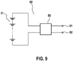
- the Figure 9 shows an embodiment of a converter cell module 60 with the second embodiment of the coupling unit 50.
- a plurality of converter cells 11, again designed as battery cells without restricting generality, are connected in series between the inputs of a coupling unit 50.
- This embodiment of the converter cell module 60 is also not limited to a series connection of converter cells 11; in turn, only a single converter cell 11 can be provided or a parallel connection or mixed-serial-parallel connection of converter cells 11.
- the first output of the coupling unit 50 is also included a first terminal 61 and the second output of the coupling unit 40 is connected to a second terminal 62.
- the converter cell module 60 offers Figures 5 and 6 the advantage that the converter cells 11 can be decoupled from the remaining energy converter on both sides by the coupling unit 50, which enables a safe exchange during operation, since the dangerous high total voltage of the remaining converter cell modules of the energy converter is not applied to any pole of the converter cells 11.
- each converter strand has two converter cell modules 70-1 and 70-2 with a first polarity and two converter cell modules 80-1 and 80-2 with an opposite second polarity.
- the converter cell modules 70-1, 70-2 on the one hand and 80-1, 80-2 on the other hand can be constructed identically internally, but are externally connected in the opposite direction.
- the converter strand of the energy converter of the invention can of course also be constructed with only one converter cell module of each of the two polarities or with numbers greater than two. However, the same number of converter cell modules are preferably provided per polarity.
- the converter cell modules 70-1, 70-2, 80-1 and 80-2 are connected in series between an output terminal 81 of the converter string and a reference potential (usually ground), the converter cell modules being connected in such a way that a partial string is connected to the converter cell modules 70-1, 70-2 of the first polarity and one with the converter cell modules 80-1, 80-2 of the second polarity, which in turn are connected in series.
- a reference potential usually ground
- Figure 13 shows an embodiment in which the converter cell modules 70-1, 70-2 of the first polarity to one branch and the converter cell modules 80-1, 80-2 of the second polarity connected to another branch and the two branches in parallel between the output terminal 81 and that Reference potential can be switched.
- at least one converter cell module of the sub-strand that is inactive is switched to a high-resistance state in order not to short-circuit the active converter cell modules of the other sub-strand via the inactive sub-strand.
- the converter strand can additionally charge and disconnect devices or disconnect devices as in Figure 2 provided if safety regulations so require.
- such isolation devices are not necessary according to the invention because the converter cells 11 can be decoupled from the connections of the converter line by the coupling units contained in the converter cell modules.
- FIG 14 shows a drive system with an embodiment of the energy converter according to the invention.
- the energy converter has three converter trains 90-1, 90-2 and 90-3, which are each connected directly to an input of a drive motor 13. Since most of the available electric motors are designed for operation with three phase signals, the energy converter of the invention preferably has exactly three converter trains.
- the energy converter of the invention has the further advantage that the functionality of a pulse-controlled inverter is already in the energy converter is integrated.
- a control unit of the energy converter activates (or deactivates) a variable number of converter cell modules 40 or 60 of a converter line
- there is a voltage at the output of the converter line that is proportional to the number of activated converter cell modules 40 or 60, which is between 0 V and the full output voltage of the converter line can, available.
- Figure 15 shows an exemplary time course of the output voltages of an embodiment variant of the energy converter according to the invention.
- the output voltages of the energy converter V are plotted against the time t.
- the reference numerals 100-b, 101-bundle 102-b indicate three (ideal) sine waves desired for an exemplary application, each of which have a positive and a negative half phase and are mutually phase-shifted by 120 °.
- the ideal sine waves 100-b, 101-b, 102-b are each generated approximately by one converter strand of the energy converter according to the invention by means of a discrete-value voltage curve 100-a, 101-a, 102-a.
- the deviations of the discrete-value voltage curves 100-a, 101-a, 102-a from the ideal curve 100-b, 101-b or 102-b depend in terms of their size on the number of converter cells 11 which are in a battery module 40 or 60 in Series are connected, as well as their respective cell voltage.
- the more converter cells 11 are connected in series in a converter cell module the more precisely the discrete-value voltage curve 100-a, 101-a, 102-a can follow the idealized curve 100-b, 101-b, 102-b. In normal applications, however, the relatively small deviations do not affect the function of the overall system.
- the three converter strands preferably generate output voltages which are phase-shifted by 120 °, so that a three-phase supply voltage is provided for an electrical drive system or the like.
Landscapes
- Engineering & Computer Science (AREA)
- Power Engineering (AREA)
- Transportation (AREA)
- Mechanical Engineering (AREA)
- Electric Propulsion And Braking For Vehicles (AREA)
- Inverter Devices (AREA)
- Charge And Discharge Circuits For Batteries Or The Like (AREA)
- Secondary Cells (AREA)
- Dc-Dc Converters (AREA)
Claims (9)
- Convertisseur d'énergie, destiné à délivrer de l'énergie électrique, comprenant une pluralité de branches de convertisseur (90-1, 90-2, 90-3), chaque branche de convertisseur (90-1, 90-2, 90-3) comprenant au moins un premier module de cellule de convertisseur (70-1, 70-2) et un deuxième module de cellule de convertisseur (80-1, 80-2), l'au moins un premier et l'au moins un deuxième module de cellule de convertisseur (70-1, 70-2 ; 80-1, 80-2) comprenant respectivement au moins une cellule de convertisseur (11), réalisée sous la forme d'une cellule de convertisseur d'énergie, notamment sous la forme d'une cellule de batterie, et une unité de connexion (30, 50), l'au moins une cellule de convertisseur (11) étant connectée entre une première entrée (31, 51) et une deuxième entrée (32, 52) de l'unité de connexion (30, 50) et l'unité de connexion (30, 50) étant configurée pour, en présence d'un premier signal de commande, commuter l'au moins une cellule de convertisseur (11) entre une première borne (41, 61) du module de cellule de convertisseur (70-1, 70-2 ; 80-1, 80-2) et une deuxième borne (42, 62) du module de cellule de convertisseur (70-1, 70-2 ; 80-1, 80-2) et, en présence d'un deuxième signal de commande, relier la première borne (41, 61) à la deuxième borne (42, 62), caractérisé en ce que l'au moins une cellule de convertisseur (11) de l'au moins un premier module de cellule de convertisseur (70-1, 70-2) est connectée dans une première polarité entre la première entrée (32, 51) et la deuxième entrée (31, 52) de l'unité de connexion (30, 50) de l'au moins un premier module de cellule de convertisseur (70-1, 70-2) et l'au moins une cellule de convertisseur (11) de l'au moins un deuxième module de cellule de convertisseur (80-1, 80-2) dans une deuxième polarité, opposée à la première polarité, entre la première entrée (31, 51) et la deuxième entrée (32, 52) de l'unité de connexion (30, 50) de l'au moins un deuxième module de cellule de convertisseur (80-1, 80-2) respectif, le convertisseur d'énergie avec une unité de commande, laquelle est configurée pour, pendant un premier intervalle de temps, délivrer le premier signal de commande à l'au moins un premier module de cellule de convertisseur (70-1, 70-2) d'une branche de convertisseur (90-1, 90-2, 90-3) et le deuxième signal de commande à l'au moins un deuxième module de cellule de convertisseur (80-1, 80-2) de ladite branche de convertisseur (90-1, 90-2, 90-3) et, dans un deuxième intervalle de temps qui suit le premier intervalle de temps, délivrer le deuxième signal de commande à l'au moins un premier module de cellule de convertisseur (70-1, 70-2) de ladite branche de convertisseur (90-1, 90-2, 90-3) et le premier signal de commande à l'au moins un deuxième module de cellule de convertisseur (80-1, 80-2) de ladite branche de convertisseur (90-1, 90-2, 90-3) et régler ainsi une tension de sortie de la branche de convertisseur (90-1, 90-2, 90-3) avec un premier signe pendant le premier intervalle de temps et avec un deuxième signe, opposé au premier signe, pendant le deuxième intervalle de temps.
- Convertisseur d'énergie selon la revendication 1, avec lequel chaque branche de convertisseur (90-1, 90-2, 90-3) possède une pluralité de premiers modules de cellule de convertisseur (70-1, 70-2) et une pluralité de deuxièmes modules de cellule de convertisseur (80-1, 80-2), l'unité de commande étant configurée pour régler une tension de sortie sinusoïdale (100-a, 101-a, 102-a) pour chaque branche de convertisseur (90-1, 90-2, 90-3).
- Convertisseur d'énergie selon la revendication 2, avec lequel l'unité de commande est configurée pour régler la tension de sortie sinusoïdale avec une fréquence qui peut être prédéfinie.
- Convertisseur d'énergie selon l'une des revendications 2 et 3, avec lequel l'unité de commande est configurée pour régler une tension de sortie sinusoïdale (100-a, 101-a, 102-a) pour chaque branche de convertisseur (90-1, 90-2, 90-3), laquelle est déphasée par rapport aux tensions de sortie sinusoïdales des autres branches de convertisseur (90-1, 90-2, 90-3) respectives.
- Convertisseur d'énergie selon l'une des revendications précédentes, avec lequel l'unité de connexion (30) possède une première sortie (33) et est configurée pour, en présence du premier signal de commande, relier soit la première entrée (31), soit la deuxième entrée (32), à la première sortie (33).
- Convertisseur d'énergie selon l'une des revendications 1 à 4, avec lequel l'unité de connexion (50) possède une première sortie (53) et une deuxième sortie (54) et est configurée pour, en présence du premier signal de commande, relier la première entrée (51) à la première sortie (53) et la deuxième entrée (52) à la deuxième sortie (54) et, en présence du deuxième signal de commande, déconnecter la première entrée (51) de la première sortie (53) et la deuxième entrée (52) de la deuxième sortie (54) et relier la première sortie (53) à la deuxième sortie (54).
- Convertisseur d'énergie selon l'une des revendications précédentes, avec lequel les cellules de convertisseur (11) sont des cellules de batterie ou des cellules solaires.
- Véhicule automobile comprenant un moteur de propulsion électrique (113) servant à la propulsion du véhicule automobile et comprenant un convertisseur d'énergie selon l'une des revendications précédentes relié au moteur de propulsion électrique (113).
- Procédé pour alimenter un système de propulsion électrique, comprenant les étapes suivantes :a) fourniture d'un convertisseur d'énergie selon l'une des revendications 1 à 7 ;b) connexion du convertisseur d'énergie à un système de propulsion électrique ; etc) réglage d'une tension de sortie du convertisseur d'énergie avec un premier signe pendant un premier intervalle de temps et avec un deuxième signe, opposé au premier signe, pendant un deuxième intervalle de temps.
Applications Claiming Priority (2)
| Application Number | Priority Date | Filing Date | Title |
|---|---|---|---|
| DE102010038866A DE102010038866A1 (de) | 2010-08-04 | 2010-08-04 | Energiewandler zum Ausgeben elektrischer Energie |
| PCT/EP2011/059345 WO2012016734A1 (fr) | 2010-08-04 | 2011-06-07 | Convertisseur d'énergie multiphase destiné à fournir de l'énergie électrique |
Publications (2)
| Publication Number | Publication Date |
|---|---|
| EP2601736A1 EP2601736A1 (fr) | 2013-06-12 |
| EP2601736B1 true EP2601736B1 (fr) | 2019-12-25 |
Family
ID=44352187
Family Applications (1)
| Application Number | Title | Priority Date | Filing Date |
|---|---|---|---|
| EP11727143.7A Active EP2601736B1 (fr) | 2010-08-04 | 2011-06-07 | Convertisseur d'énergie multiphase destiné à fournir de l'énergie électrique |
Country Status (7)
| Country | Link |
|---|---|
| US (1) | US20130293169A1 (fr) |
| EP (1) | EP2601736B1 (fr) |
| JP (1) | JP5698356B2 (fr) |
| KR (1) | KR101486896B1 (fr) |
| CN (1) | CN103053107B (fr) |
| DE (1) | DE102010038866A1 (fr) |
| WO (1) | WO2012016734A1 (fr) |
Families Citing this family (1)
| Publication number | Priority date | Publication date | Assignee | Title |
|---|---|---|---|---|
| DE102015112512A1 (de) * | 2015-07-30 | 2017-02-02 | Dr. Ing. H.C. F. Porsche Aktiengesellschaft | Einzelmodul, elektrisches Umrichtersystem und Batteriesystem |
Citations (3)
| Publication number | Priority date | Publication date | Assignee | Title |
|---|---|---|---|---|
| DE10103031A1 (de) * | 2001-01-24 | 2002-07-25 | Rainer Marquardt | Stromrichterschaltungen mit verteilten Energiespeichern |
| DE102008032813A1 (de) * | 2008-07-11 | 2010-01-21 | Siemens Aktiengesellschaft | Netzanbindung von Solarzellen |
| US20100141201A1 (en) * | 2009-04-17 | 2010-06-10 | Nathan Bowman Littrell | Methods and systems for charging electric vehicles using solar power |
Family Cites Families (5)
| Publication number | Priority date | Publication date | Assignee | Title |
|---|---|---|---|---|
| US3100851A (en) * | 1959-11-03 | 1963-08-13 | Ling Temco Vought Inc | High power synthetic waveform generator |
| US4680690A (en) * | 1984-10-19 | 1987-07-14 | Dickerson Arthur F | Inverter for use with solar arrays |
| DE4212864A1 (de) * | 1991-04-18 | 1992-10-22 | Jovan Prof Dr Antula | Spannungswandler mit potentialfreiem ausgang |
| US6198178B1 (en) | 1999-12-21 | 2001-03-06 | International Power Systems, Inc. | Step wave power converter |
| ITVA20010022A1 (it) * | 2001-07-11 | 2003-01-11 | Chemieco Srl | Invertitore statico di tensione per sistema a batterie |
-
2010
- 2010-08-04 DE DE102010038866A patent/DE102010038866A1/de not_active Withdrawn
-
2011
- 2011-06-07 CN CN201180037922.4A patent/CN103053107B/zh active Active
- 2011-06-07 JP JP2013522148A patent/JP5698356B2/ja active Active
- 2011-06-07 US US13/813,563 patent/US20130293169A1/en not_active Abandoned
- 2011-06-07 KR KR1020137005398A patent/KR101486896B1/ko active Active
- 2011-06-07 EP EP11727143.7A patent/EP2601736B1/fr active Active
- 2011-06-07 WO PCT/EP2011/059345 patent/WO2012016734A1/fr not_active Ceased
Patent Citations (3)
| Publication number | Priority date | Publication date | Assignee | Title |
|---|---|---|---|---|
| DE10103031A1 (de) * | 2001-01-24 | 2002-07-25 | Rainer Marquardt | Stromrichterschaltungen mit verteilten Energiespeichern |
| DE102008032813A1 (de) * | 2008-07-11 | 2010-01-21 | Siemens Aktiengesellschaft | Netzanbindung von Solarzellen |
| US20100141201A1 (en) * | 2009-04-17 | 2010-06-10 | Nathan Bowman Littrell | Methods and systems for charging electric vehicles using solar power |
Also Published As
| Publication number | Publication date |
|---|---|
| DE102010038866A1 (de) | 2012-02-09 |
| CN103053107B (zh) | 2016-02-17 |
| EP2601736A1 (fr) | 2013-06-12 |
| WO2012016734A1 (fr) | 2012-02-09 |
| KR20130036370A (ko) | 2013-04-11 |
| KR101486896B1 (ko) | 2015-02-04 |
| CN103053107A (zh) | 2013-04-17 |
| JP2013541926A (ja) | 2013-11-14 |
| JP5698356B2 (ja) | 2015-04-08 |
| US20130293169A1 (en) | 2013-11-07 |
Similar Documents
| Publication | Publication Date | Title |
|---|---|---|
| EP2601737B1 (fr) | Convertisseur d'énergie destiné à fournir de l'énergie électrique | |
| EP2559136B1 (fr) | Batterie à tension de sortie variable | |
| EP2673860B1 (fr) | Charger un dispositif de stockage d'energie | |
| EP2619842B1 (fr) | Réseau d'alimentation électrique et procédé pour charger au moins un élément accumulateur servant d'accumulateur d'énergie pour un circuit cc intermédiaire dans un réseau d'alimentation électrique | |
| EP2673829B1 (fr) | Stockage d'énergie contrôlable et procédé d'exploitation d'un stockage d'énergie contrôlable | |
| EP2619027B1 (fr) | Système de batterie doté d'un convertisseur indirect de tension continue à réglage variable | |
| EP3562701A1 (fr) | Découplage basse tension composé d'un système modulaire accumulateur d'énergie-onduleur | |
| EP2619874B1 (fr) | Système pour charger un accumulateur d'énergie et procédé de fonctionnement du système de chargement | |
| DE102021208773B3 (de) | Traktionsnetz für ein Elektrofahrzeug und Verfahren zum Laden | |
| WO2013143805A2 (fr) | Système de batterie, véhicule automobile comprenant un système de batterie et procédé pour mettre en service un système de batterie | |
| DE102012205395A1 (de) | Batteriesystem, Verfahren zum Laden von Batteriemodulen, sowie Verfahren zum Balancieren von Batteriemodulen | |
| DE102013202650B4 (de) | Interne Energieversorgung von Energiespeichermodulen für eine Energiespeichereinrichtung und Energiespeichereinrichtung mit solchem | |
| DE102014212935A1 (de) | Vorrichtung zum Bereitstellen einer elektrischen Spannung mit seriellem Stack-Umrichter sowie Antriebsanordnung | |
| WO2014154495A1 (fr) | Dispositif accumulateur d'énergie et système comprenant un dispositif accumulateur d'énergie | |
| WO2017186392A1 (fr) | Machine électrique pourvue de deux onduleurs raccordés | |
| WO2012038210A2 (fr) | Réseau d'alimentation en énergie et procédé pour charger au moins une source d'alimentation en énergie servant d'accumulateur d'énergie pour un circuit intermédiaire à tension continue dans un réseau d'alimentation en énergie | |
| DE102011003940A1 (de) | System mit einer elektrisch erregten Maschine | |
| EP2601736B1 (fr) | Convertisseur d'énergie multiphase destiné à fournir de l'énergie électrique | |
| DE102010042718A1 (de) | Verfahren zur Steuerung einer Batterie mit variabler Ausgangsspannung | |
| WO2012163572A2 (fr) | Dispositif d'alimentation en énergie pour circuits onduleurs | |
| EP2608398A1 (fr) | Convertisseur de puissance modulaire | |
| DE102017130387A1 (de) | Umrichter-Vorrichtung, Anordnung mit mehreren solcher Umrichter-Vorrichtungen sowie Verfahren zum Betreiben einer Umrichter-Vorrichtung | |
| DE102023103759B3 (de) | Erweiterbare Multilevelkonverter-Schaltungstopologie mit geschalteten Kondensatoren | |
| WO2020030356A1 (fr) | Système d'énergie électrique comprenant des piles à combustible | |
| WO2012079822A1 (fr) | Unité de couplage et module de batterie pourvu d'une telle unité de couplage |
Legal Events
| Date | Code | Title | Description |
|---|---|---|---|
| PUAI | Public reference made under article 153(3) epc to a published international application that has entered the european phase |
Free format text: ORIGINAL CODE: 0009012 |
|
| 17P | Request for examination filed |
Effective date: 20130304 |
|
| AK | Designated contracting states |
Kind code of ref document: A1 Designated state(s): AL AT BE BG CH CY CZ DE DK EE ES FI FR GB GR HR HU IE IS IT LI LT LU LV MC MK MT NL NO PL PT RO RS SE SI SK SM TR |
|
| DAX | Request for extension of the european patent (deleted) | ||
| STAA | Information on the status of an ep patent application or granted ep patent |
Free format text: STATUS: EXAMINATION IS IN PROGRESS |
|
| 17Q | First examination report despatched |
Effective date: 20180123 |
|
| REG | Reference to a national code |
Ref country code: DE Ref legal event code: R079 Ref document number: 502011016348 Country of ref document: DE Free format text: PREVIOUS MAIN CLASS: H02M0007537000 Ipc: H02P0027140000 |
|
| GRAP | Despatch of communication of intention to grant a patent |
Free format text: ORIGINAL CODE: EPIDOSNIGR1 |
|
| STAA | Information on the status of an ep patent application or granted ep patent |
Free format text: STATUS: GRANT OF PATENT IS INTENDED |
|
| RIC1 | Information provided on ipc code assigned before grant |
Ipc: H02M 7/483 20070101ALI20190725BHEP Ipc: H02P 27/14 20060101AFI20190725BHEP Ipc: H02M 7/44 20060101ALI20190725BHEP |
|
| INTG | Intention to grant announced |
Effective date: 20190822 |
|
| GRAS | Grant fee paid |
Free format text: ORIGINAL CODE: EPIDOSNIGR3 |
|
| GRAA | (expected) grant |
Free format text: ORIGINAL CODE: 0009210 |
|
| STAA | Information on the status of an ep patent application or granted ep patent |
Free format text: STATUS: THE PATENT HAS BEEN GRANTED |
|
| AK | Designated contracting states |
Kind code of ref document: B1 Designated state(s): AL AT BE BG CH CY CZ DE DK EE ES FI FR GB GR HR HU IE IS IT LI LT LU LV MC MK MT NL NO PL PT RO RS SE SI SK SM TR |
|
| REG | Reference to a national code |
Ref country code: GB Ref legal event code: FG4D Free format text: NOT ENGLISH |
|
| REG | Reference to a national code |
Ref country code: CH Ref legal event code: EP |
|
| REG | Reference to a national code |
Ref country code: AT Ref legal event code: REF Ref document number: 1218252 Country of ref document: AT Kind code of ref document: T Effective date: 20200115 |
|
| REG | Reference to a national code |
Ref country code: DE Ref legal event code: R096 Ref document number: 502011016348 Country of ref document: DE |
|
| REG | Reference to a national code |
Ref country code: IE Ref legal event code: FG4D Free format text: LANGUAGE OF EP DOCUMENT: GERMAN |
|
| RAP2 | Party data changed (patent owner data changed or rights of a patent transferred) |
Owner name: ROBERT BOSCH GMBH Owner name: SAMSUNG SDI CO., LTD. |
|
| REG | Reference to a national code |
Ref country code: NL Ref legal event code: MP Effective date: 20191225 |
|
| PG25 | Lapsed in a contracting state [announced via postgrant information from national office to epo] |
Ref country code: LT Free format text: LAPSE BECAUSE OF FAILURE TO SUBMIT A TRANSLATION OF THE DESCRIPTION OR TO PAY THE FEE WITHIN THE PRESCRIBED TIME-LIMIT Effective date: 20191225 Ref country code: FI Free format text: LAPSE BECAUSE OF FAILURE TO SUBMIT A TRANSLATION OF THE DESCRIPTION OR TO PAY THE FEE WITHIN THE PRESCRIBED TIME-LIMIT Effective date: 20191225 Ref country code: BG Free format text: LAPSE BECAUSE OF FAILURE TO SUBMIT A TRANSLATION OF THE DESCRIPTION OR TO PAY THE FEE WITHIN THE PRESCRIBED TIME-LIMIT Effective date: 20200325 Ref country code: NO Free format text: LAPSE BECAUSE OF FAILURE TO SUBMIT A TRANSLATION OF THE DESCRIPTION OR TO PAY THE FEE WITHIN THE PRESCRIBED TIME-LIMIT Effective date: 20200325 Ref country code: GR Free format text: LAPSE BECAUSE OF FAILURE TO SUBMIT A TRANSLATION OF THE DESCRIPTION OR TO PAY THE FEE WITHIN THE PRESCRIBED TIME-LIMIT Effective date: 20200326 Ref country code: SE Free format text: LAPSE BECAUSE OF FAILURE TO SUBMIT A TRANSLATION OF THE DESCRIPTION OR TO PAY THE FEE WITHIN THE PRESCRIBED TIME-LIMIT Effective date: 20191225 Ref country code: LV Free format text: LAPSE BECAUSE OF FAILURE TO SUBMIT A TRANSLATION OF THE DESCRIPTION OR TO PAY THE FEE WITHIN THE PRESCRIBED TIME-LIMIT Effective date: 20191225 |
|
| REG | Reference to a national code |
Ref country code: LT Ref legal event code: MG4D |
|
| PG25 | Lapsed in a contracting state [announced via postgrant information from national office to epo] |
Ref country code: HR Free format text: LAPSE BECAUSE OF FAILURE TO SUBMIT A TRANSLATION OF THE DESCRIPTION OR TO PAY THE FEE WITHIN THE PRESCRIBED TIME-LIMIT Effective date: 20191225 Ref country code: RS Free format text: LAPSE BECAUSE OF FAILURE TO SUBMIT A TRANSLATION OF THE DESCRIPTION OR TO PAY THE FEE WITHIN THE PRESCRIBED TIME-LIMIT Effective date: 20191225 |
|
| PG25 | Lapsed in a contracting state [announced via postgrant information from national office to epo] |
Ref country code: AL Free format text: LAPSE BECAUSE OF FAILURE TO SUBMIT A TRANSLATION OF THE DESCRIPTION OR TO PAY THE FEE WITHIN THE PRESCRIBED TIME-LIMIT Effective date: 20191225 |
|
| PG25 | Lapsed in a contracting state [announced via postgrant information from national office to epo] |
Ref country code: RO Free format text: LAPSE BECAUSE OF FAILURE TO SUBMIT A TRANSLATION OF THE DESCRIPTION OR TO PAY THE FEE WITHIN THE PRESCRIBED TIME-LIMIT Effective date: 20191225 Ref country code: CZ Free format text: LAPSE BECAUSE OF FAILURE TO SUBMIT A TRANSLATION OF THE DESCRIPTION OR TO PAY THE FEE WITHIN THE PRESCRIBED TIME-LIMIT Effective date: 20191225 Ref country code: NL Free format text: LAPSE BECAUSE OF FAILURE TO SUBMIT A TRANSLATION OF THE DESCRIPTION OR TO PAY THE FEE WITHIN THE PRESCRIBED TIME-LIMIT Effective date: 20191225 Ref country code: PT Free format text: LAPSE BECAUSE OF FAILURE TO SUBMIT A TRANSLATION OF THE DESCRIPTION OR TO PAY THE FEE WITHIN THE PRESCRIBED TIME-LIMIT Effective date: 20200520 Ref country code: EE Free format text: LAPSE BECAUSE OF FAILURE TO SUBMIT A TRANSLATION OF THE DESCRIPTION OR TO PAY THE FEE WITHIN THE PRESCRIBED TIME-LIMIT Effective date: 20191225 |
|
| PGFP | Annual fee paid to national office [announced via postgrant information from national office to epo] |
Ref country code: FR Payment date: 20200623 Year of fee payment: 10 |
|
| PG25 | Lapsed in a contracting state [announced via postgrant information from national office to epo] |
Ref country code: SK Free format text: LAPSE BECAUSE OF FAILURE TO SUBMIT A TRANSLATION OF THE DESCRIPTION OR TO PAY THE FEE WITHIN THE PRESCRIBED TIME-LIMIT Effective date: 20191225 Ref country code: IS Free format text: LAPSE BECAUSE OF FAILURE TO SUBMIT A TRANSLATION OF THE DESCRIPTION OR TO PAY THE FEE WITHIN THE PRESCRIBED TIME-LIMIT Effective date: 20200425 Ref country code: SM Free format text: LAPSE BECAUSE OF FAILURE TO SUBMIT A TRANSLATION OF THE DESCRIPTION OR TO PAY THE FEE WITHIN THE PRESCRIBED TIME-LIMIT Effective date: 20191225 |
|
| PGFP | Annual fee paid to national office [announced via postgrant information from national office to epo] |
Ref country code: GB Payment date: 20200625 Year of fee payment: 10 |
|
| REG | Reference to a national code |
Ref country code: DE Ref legal event code: R097 Ref document number: 502011016348 Country of ref document: DE |
|
| PG25 | Lapsed in a contracting state [announced via postgrant information from national office to epo] |
Ref country code: ES Free format text: LAPSE BECAUSE OF FAILURE TO SUBMIT A TRANSLATION OF THE DESCRIPTION OR TO PAY THE FEE WITHIN THE PRESCRIBED TIME-LIMIT Effective date: 20191225 Ref country code: DK Free format text: LAPSE BECAUSE OF FAILURE TO SUBMIT A TRANSLATION OF THE DESCRIPTION OR TO PAY THE FEE WITHIN THE PRESCRIBED TIME-LIMIT Effective date: 20191225 |
|
| PLBE | No opposition filed within time limit |
Free format text: ORIGINAL CODE: 0009261 |
|
| STAA | Information on the status of an ep patent application or granted ep patent |
Free format text: STATUS: NO OPPOSITION FILED WITHIN TIME LIMIT |
|
| PG25 | Lapsed in a contracting state [announced via postgrant information from national office to epo] |
Ref country code: SI Free format text: LAPSE BECAUSE OF FAILURE TO SUBMIT A TRANSLATION OF THE DESCRIPTION OR TO PAY THE FEE WITHIN THE PRESCRIBED TIME-LIMIT Effective date: 20191225 |
|
| 26N | No opposition filed |
Effective date: 20200928 |
|
| PG25 | Lapsed in a contracting state [announced via postgrant information from national office to epo] |
Ref country code: MC Free format text: LAPSE BECAUSE OF FAILURE TO SUBMIT A TRANSLATION OF THE DESCRIPTION OR TO PAY THE FEE WITHIN THE PRESCRIBED TIME-LIMIT Effective date: 20191225 Ref country code: IT Free format text: LAPSE BECAUSE OF FAILURE TO SUBMIT A TRANSLATION OF THE DESCRIPTION OR TO PAY THE FEE WITHIN THE PRESCRIBED TIME-LIMIT Effective date: 20191225 |
|
| REG | Reference to a national code |
Ref country code: CH Ref legal event code: PL |
|
| PG25 | Lapsed in a contracting state [announced via postgrant information from national office to epo] |
Ref country code: PL Free format text: LAPSE BECAUSE OF FAILURE TO SUBMIT A TRANSLATION OF THE DESCRIPTION OR TO PAY THE FEE WITHIN THE PRESCRIBED TIME-LIMIT Effective date: 20191225 |
|
| PG25 | Lapsed in a contracting state [announced via postgrant information from national office to epo] |
Ref country code: LU Free format text: LAPSE BECAUSE OF NON-PAYMENT OF DUE FEES Effective date: 20200607 |
|
| REG | Reference to a national code |
Ref country code: BE Ref legal event code: MM Effective date: 20200630 |
|
| PG25 | Lapsed in a contracting state [announced via postgrant information from national office to epo] |
Ref country code: IE Free format text: LAPSE BECAUSE OF NON-PAYMENT OF DUE FEES Effective date: 20200607 Ref country code: LI Free format text: LAPSE BECAUSE OF NON-PAYMENT OF DUE FEES Effective date: 20200630 Ref country code: CH Free format text: LAPSE BECAUSE OF NON-PAYMENT OF DUE FEES Effective date: 20200630 |
|
| PG25 | Lapsed in a contracting state [announced via postgrant information from national office to epo] |
Ref country code: BE Free format text: LAPSE BECAUSE OF NON-PAYMENT OF DUE FEES Effective date: 20200630 |
|
| REG | Reference to a national code |
Ref country code: AT Ref legal event code: MM01 Ref document number: 1218252 Country of ref document: AT Kind code of ref document: T Effective date: 20200607 |
|
| PG25 | Lapsed in a contracting state [announced via postgrant information from national office to epo] |
Ref country code: AT Free format text: LAPSE BECAUSE OF NON-PAYMENT OF DUE FEES Effective date: 20200607 |
|
| GBPC | Gb: european patent ceased through non-payment of renewal fee |
Effective date: 20210607 |
|
| PG25 | Lapsed in a contracting state [announced via postgrant information from national office to epo] |
Ref country code: GB Free format text: LAPSE BECAUSE OF NON-PAYMENT OF DUE FEES Effective date: 20210607 |
|
| PG25 | Lapsed in a contracting state [announced via postgrant information from national office to epo] |
Ref country code: TR Free format text: LAPSE BECAUSE OF FAILURE TO SUBMIT A TRANSLATION OF THE DESCRIPTION OR TO PAY THE FEE WITHIN THE PRESCRIBED TIME-LIMIT Effective date: 20191225 Ref country code: MT Free format text: LAPSE BECAUSE OF FAILURE TO SUBMIT A TRANSLATION OF THE DESCRIPTION OR TO PAY THE FEE WITHIN THE PRESCRIBED TIME-LIMIT Effective date: 20191225 Ref country code: FR Free format text: LAPSE BECAUSE OF NON-PAYMENT OF DUE FEES Effective date: 20210630 Ref country code: CY Free format text: LAPSE BECAUSE OF FAILURE TO SUBMIT A TRANSLATION OF THE DESCRIPTION OR TO PAY THE FEE WITHIN THE PRESCRIBED TIME-LIMIT Effective date: 20191225 |
|
| PG25 | Lapsed in a contracting state [announced via postgrant information from national office to epo] |
Ref country code: MK Free format text: LAPSE BECAUSE OF FAILURE TO SUBMIT A TRANSLATION OF THE DESCRIPTION OR TO PAY THE FEE WITHIN THE PRESCRIBED TIME-LIMIT Effective date: 20191225 |
|
| PGFP | Annual fee paid to national office [announced via postgrant information from national office to epo] |
Ref country code: DE Payment date: 20250814 Year of fee payment: 15 |