EP2602084A2 - Kunststoff-Tonne mit mehreren Anspritzpunkten - Google Patents
Kunststoff-Tonne mit mehreren Anspritzpunkten Download PDFInfo
- Publication number
- EP2602084A2 EP2602084A2 EP12195824.3A EP12195824A EP2602084A2 EP 2602084 A2 EP2602084 A2 EP 2602084A2 EP 12195824 A EP12195824 A EP 12195824A EP 2602084 A2 EP2602084 A2 EP 2602084A2
- Authority
- EP
- European Patent Office
- Prior art keywords
- plastic
- injection
- barrel
- plastic barrel
- wall
- Prior art date
- Legal status (The legal status is an assumption and is not a legal conclusion. Google has not performed a legal analysis and makes no representation as to the accuracy of the status listed.)
- Granted
Links
Images

Classifications
-
- B—PERFORMING OPERATIONS; TRANSPORTING
- B65—CONVEYING; PACKING; STORING; HANDLING THIN OR FILAMENTARY MATERIAL
- B65F—GATHERING OR REMOVAL OF DOMESTIC OR LIKE REFUSE
- B65F1/00—Refuse receptacles; Accessories therefor
- B65F1/02—Refuse receptacles; Accessories therefor without removable inserts
-
- B—PERFORMING OPERATIONS; TRANSPORTING
- B29—WORKING OF PLASTICS; WORKING OF SUBSTANCES IN A PLASTIC STATE IN GENERAL
- B29C—SHAPING OR JOINING OF PLASTICS; SHAPING OF MATERIAL IN A PLASTIC STATE, NOT OTHERWISE PROVIDED FOR; AFTER-TREATMENT OF THE SHAPED PRODUCTS, e.g. REPAIRING
- B29C45/00—Injection moulding, i.e. forcing the required volume of moulding material through a nozzle into a closed mould; Apparatus therefor
- B29C45/0025—Preventing defects on the moulded article, e.g. weld lines, shrinkage marks
-
- B—PERFORMING OPERATIONS; TRANSPORTING
- B29—WORKING OF PLASTICS; WORKING OF SUBSTANCES IN A PLASTIC STATE IN GENERAL
- B29C—SHAPING OR JOINING OF PLASTICS; SHAPING OF MATERIAL IN A PLASTIC STATE, NOT OTHERWISE PROVIDED FOR; AFTER-TREATMENT OF THE SHAPED PRODUCTS, e.g. REPAIRING
- B29C45/00—Injection moulding, i.e. forcing the required volume of moulding material through a nozzle into a closed mould; Apparatus therefor
- B29C45/0025—Preventing defects on the moulded article, e.g. weld lines, shrinkage marks
- B29C2045/0027—Gate or gate mark locations
-
- B—PERFORMING OPERATIONS; TRANSPORTING
- B29—WORKING OF PLASTICS; WORKING OF SUBSTANCES IN A PLASTIC STATE IN GENERAL
- B29L—INDEXING SCHEME ASSOCIATED WITH SUBCLASS B29C, RELATING TO PARTICULAR ARTICLES
- B29L2031/00—Other particular articles
- B29L2031/712—Containers; Packaging elements or accessories, Packages
Definitions
- the invention relates to a plastic barrel according to the preamble of claim 1.
- the generic plastic barrels have approximately centrally on the underside of the bottom surface an injection point, via which during the production of the plastic barrel the flowable plastic is injected into the mold.
- the plastic is then distributed in the mold cavity first over the surface, which later forms the bottom of the plastic barrel, and then over the cavities, which later form the walls of the plastic barrel.
- the wall thickness of the plastic barrels is sized so that even with an unintentional oscillation or dodging of the core in the injection mold sufficient strength is ensured on the wall, which has the thinnest wall thickness.
- the other wall thicknesses are therefore usually made as thick as it would actually not be necessary in view of the strength properties of the plastic for the subsequent practical operation of the plastic barrel.
- the invention has for its object to improve a generic plastic barrel to the effect that this can be produced as economically as possible, in particular with the lowest possible wall thickness can be produced.
- the invention proposes that not only is a central injection point provided on the bottom, but that at least two injection points are provided on the bottom.
- Providing two or more injection points on a plastic component is known to allow rapid filling of the mold cavity.
- this is not necessary for the production of the generic plastic barrels.
- the present proposal is initially surprising because it proposes a technically more complicated injection mold than heretofore, namely an injection mold provided with several injection points, where hitherto a single injection point was sufficient. This initially seems to be rather disadvantageous in terms of the most economical production of plastic barrels.
- the arrangement of two or more injection points on the barrel bottom is advantageous: By providing two such injection points, it is precluded that both injection points can be arranged centrally in the center of the base. In this way, when using appropriate valves on the injection nozzles of the injection mold that two different plastic streams can be metered and influenced independently during the injection process, so that in this way the propagation of the flow front of the plastic flowing into the injection mold can be controlled.
- Oscillations of the core of the injection mold can be influenced in this way: either by the typical, always recurrent behavior of this core by a corresponding system control is programmed, which controls the injection process of the plastic in a fixed programmed sequence on the mentioned valves and thus counteracts the suspected movements of the core. Or it can be provided to detect the actual movements of the core during the injection process and to control the valves in response to the behavior of the core, so that it can react in real time to movements of the core and in this way can be counteracted unwanted movements of the core ,
- the injection points can be provided at the edge of the floor, that is near a wall adjacent to the floor and accordingly far away from the center of the floor area.
- influencing the injection nozzles or injection valves has a direct effect on the flow behavior of the plastic in the adjacent wall, so that in this way the forces acting on the core from this wall surface can be optimally influenced.
- each wall is assigned its own injection point. Regardless of the distance of the injection point to the respective wall, the fact that the plastic material flowing in from each injection point strives to avoid the other plastic flows results in a flow behavior such that the plastic flows from this injection point into the wall assigned to this injection point. so that the flow progress of the plastic and thus the forces acting on the core from this wall surface can be determined individually for each of the walls provided.
- the respective injection point is arranged centrally to the wall associated with it, so that in this way it is ensured that the plastic emerging from this injection point Distributed as evenly as possible over the associated wall surface when it flows from the bottom up to the upper edge of the plastic barrel or to the corresponding provided in the injection mold cavity.
- a total of one plastic barrel is designated by 1, which serves to produce a waste container.
- the component shown in the drawings is molded in one piece from plastic.
- axle mounts 4 are provided for an axle with two wheels.
- a circumferential upper edge 5 is provided and a hinge axis 6, which is a hinge-like Attachment of a lid is used and can also be used as a handle of the trash can.
- injection points 7 are provided in each of the three embodiments, which are each arranged approximately centrally adjacent to a wall 2 adjacent to the bottom.
- injection points 7 on the bottom 2 do not serve simply to be able to simultaneously introduce more material into the mold cavity of the injection mold.
- the arrangement of the injection points 7 exclusively at the bottom 2 causes rather that in the production of the plastic barrel 1, the progress of the flow front of the plastic can be controlled individually for each of the four walls 3 by the valves in the injection mold can be controlled differently, ie depending on Requirements can be opened or closed in whole or in part.
- the plastic barrel 1 can be made particularly lightweight, material-saving and inexpensive.
Landscapes
- Engineering & Computer Science (AREA)
- Mechanical Engineering (AREA)
- Manufacturing & Machinery (AREA)
- Injection Moulding Of Plastics Or The Like (AREA)
- Containers Having Bodies Formed In One Piece (AREA)
Abstract
Description
- Die Erfindung betrifft eine Kunststofftonne nach dem Oberbegriff des Anspruchs 1.
- Gattungsgemäße Kunststofftonnen sind aus der Praxis bekannt. Es handelt sich dabei um so genannte 2-Rad-Behälter, die als Abfallbehälter dienen und ein Fassungsvermögen bis maximal 240l aufweisen. Gattungsfremd sind hingegen die noch größeren Abfallbehälter, die bis zu 1.000l fassen, als 4-Rad-Behälter ausgestaltet sind und keine tonnen- oder becherförmige Gestalt aufweisen.
- Die gattungsgemäßen Kunststofftonnen weisen etwa mittig an der Unterseite der Bodenfläche einen Anspritzpunkt auf, über den während der Herstellung der Kunststofftonne der fließfähige Kunststoff in die Form eingespritzt wird. Der Kunststoff verteilt sich dann in dem Formhohlraum zunächst über die Fläche, welche später den Boden der Kunststofftonne bildet, und anschließend über die Hohlräume, die später die Wände der Kunststofftonne bilden.
- Die Fließfront des Kunststoffes, der durch den Formhohlraum fließt, soll dabei möglichst in allen vier Wänden den gleichen Fortschritt machen, so dass die Fließfront aller Wände der Kunststofftonne möglichst gleichzeitig am oberen Rand der Kunststofftonne ankommt. Auf diese Weise wird vermieden, dass zunächst eine Wand gefüllt wird und der Kunststoff von dort in den oberen Wandhohlraum einer benachbarten, noch nicht vollständig gefüllten Wand einströmt. In einem solchen Fall könnte sich nämlich das Problem ergeben, dass die Grenzlinie zwischen diesen beiden Kunststoffströmen, die sich beim Aufeinandertreffen dieser beiden Kunststoffströme ergibt, zu einer Schwachstelle in der Kunststofftonne führen kann. Diese Schwachstelle im oberen Bereich, nahe dem oberen Rand der Kunststofftonne, könnte bei der späteren Handhabung der Kunststofftonne zu deren vorzeitigen Versagen führen, da die Kunststofftonnen üblicherweise am oberen Rand angehoben und gehandhabt werden. Dies trifft insbesondere für Kunststofftonnen zu, die als Abfalltonnen ausgestaltet sind.
- Auf Grund der becherförmigen Ausgestaltung der Kunststofftonne mit im Vergleich zur Bodenfläche hohen Wänden besteht in der Praxis das Problem, dass der Kern der Spritzgussform, der den inneren Hohlraum der Kunststofftonne bestimmt, angesichts der beim Spritzvorgang herrschenden Drücke von mehreren hundert bar, häufig mehr als 1000 bar, nicht millimetergenau seine Position beibehalten kann, denn er ist ja als eine Art frei ragender Zapfen nur an seinem einen Stirnende gehalten, welches der Bodenfläche der herzustellenden Kunststofftonne gegenüberliegt.
- Aus diesem Grund wird die Wandstärke der Kunststofftonnen so groß bemessen, dass auch bei einem unbeabsichtigten Pendeln oder Ausweichen des Kerns in der Spritzgießform eine ausreichende Festigkeit auf der Wand sichergestellt ist, welche die dünnste Wandstärke aufweist. Die übrigen Wandstärken werden daher üblicherweise so dick ausgeführt, wie es angesichts der Festigkeitseigenschaften des Kunststoffs für den späteren Praxisbetrieb der Kunststofftonne eigentlich nicht notwendig wäre. Der Erfindung liegt die Aufgabe zugrunde, eine gattungsgemäße Kunststofftonne dahingehend zu verbessern, dass diese möglichst wirtschaftlich hergestellt werden kann, insbesondere mit einer möglichst geringen Wandstärke hergestellt werden kann.
- Diese Aufgabe wird durch eine Kunststofftonne mit den Merkmalen des Anspruchs 1 gelöst.
- Die Erfindung schlägt mit anderen Worten vor, dass nicht nur ein zentraler Anspritzpunkt am Boden vorgesehen ist, sondern dass wenigstens zwei Anspritzpunkte am Boden vorgesehen sind. Zwei oder mehr Anspritzpunkte an einem Kunststoffbauteil vorzusehen ist bekannt, um eine schnelle Füllung des Formhohlraums zu ermöglichen. Für die Herstellung der gattungsgemäßen Kunststofftonnen ist dies jedoch nicht erforderlich. Insofern ist der vorliegende Vorschlag zunächst überraschend, weil er eine technisch aufwendigere Spritzgießform als bislang vorschlägt, nämlich eine mit mehreren Anspritzpunkten versehene Spritzgießform, wo bislang ein einziger Anspritzpunkt ausreichend war. Dies scheint zunächst im Sinne einer möglichst wirtschaftlichen Fertigung der Kunststofftonnen eher nachteilig zu sein.
- Tatsächlich jedoch ist die Anordnung von zwei oder mehr Anspritzpunkten am Tonnenboden vorteilhaft: Dadurch, dass zwei derartige Anspritzpunkte vorgesehen sind, ist ausgeschlossen, dass beide Anspritzpunkte zentral in der Mitte des Bodens angeordnet sein können. Auf diese Weise ergibt sich bei Verwendung entsprechender Ventile an den Einspritzdüsen der Spritzgießform, dass zwei verschiedene Kunststoffströme während des Einspritzvorgangs unabhängig voneinander dosiert und beeinflusst werden können, so dass auf diese Weise die Ausbreitung der Fließfront des in die Spritzgießform einströmenden Kunststoffs gesteuert werden kann.
- Pendelbewegungen des Kerns der Spritzgießform können auf diese Weise beeinflusst werden: entweder anhand des typischen, stets wiederkehrenden Verhaltens dieses Kerns, indem eine entsprechende Anlagensteuerung programmiert wird, welche über die erwähnten Ventile den Einspritzvorgang des Kunststoffs in einen fest programmierten Ablauf steuert und so den mutmaßlichen Bewegungen des Kerns entgegengewirkt. Oder es kann vorgesehen sein, die tatsächlichen Bewegungen des Kerns während des Einspritzvorgangs zu erfassen und die Ventile in Reaktion auf das Verhalten des Kerns anzusteuern, so dass in Echtzeit auf Bewegungen des Kerns reagiert werden kann und auf diese Weise unerwünschten Bewegungen des Kerns entgegengewirkt werden kann.
- Vorteilhaft können die Anspritzpunkte am Rand des Bodens vorgesehen sein, also nahe einer an den Boden grenzenden Wand und dementsprechend weit entfernt von dem Mittelpunkt der Bodenfläche. Auf diese Weise wirkt sich eine Beeinflussung der Einspritzdüsen bzw. Einspritzventile unmittelbar auf das Fliesverhalten des Kunststoffs in der benachbarten Wand aus, so dass hierdurch die von dieser Wandfläche auf den Kern einwirkenden Kräfte optimal beeinflusst werden können.
- Vorteilhaft kann vorgesehen sein, dass jeder Wand ein eigener Anspritzpunkt zugeordnet ist. Unabhängig von dem Abstand des Anspritzpunktes zu der jeweiligen Wand wird sich dadurch, dass von jedem Anspritzpunkt der dort einströmende Kunststoff den anderen Kunststoffströmen auszuweichen bestrebt ist, ein Strömungsverhalten in der Art ergeben, dass von diesem Anspritzpunkt der Kunststoff in die diesem Anspritzpunkt zugeordnete Wand strömt, so dass für jede der vorgesehenen Wände jeweils individuell der Fließfortschritt des Kunststoffs und somit die auf den Kern von dieser Wandfläche her einwirkenden Kräfte bestimmt werden können.
- Vorteilhaft ist der jeweilige Anspritzpunkt mittig zu der ihm zugeordneten Wand angeordnet, so dass auf diese Weise sichergestellt ist, dass der aus diesem Anspritzpunkt austretende Kunststoff sich möglichst gleichmäßig über die zugeordnete Wandfläche verteilt, wenn er vom Boden nach oben zum oberen Rand der Kunststofftonne bzw. zu dem entsprechenden in der Spritzgießform vorgesehenen Hohlraum strömt.
- Angesichts der hohen Einspritzdrücke ist der Einfluss der Schwerkraft auf die Verteilung der Kunststoffschmelze vernachlässigbar. Während des Herstellungsverfahrens kann daher vorgesehen sein, dass der Boden der Kunststofftonne unten vorgesehen ist oder aber auch seitlich oder gar oben. Wenn von einem "unten" vorgesehenen Boden und einem "oberen Rand" und von einem "Aufsteigen" der Kunststoffschmelze vom Boden zum oberen Rand die Rede ist, so bedeutet dies im Rahmen des vorliegenden Vorschlags lediglich eine Orts- oder Richtungsangabe, die Bezug nimmt auf die später aufrecht stehende Kunststofftonne.
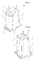
- Ein Ausführungsbeispiel der Erfindung wird anhand der rein schematischen Zeichnungen nachfolgend näher erläutert. Dabei zeigen die
- Fig. 1 - 3
- drei unterschiedliche Ausführungsbeispiele von Kunststofftonnen mit unterschiedlichen Fassungsvermögen.
- In den Zeichnungen ist jeweils mit 1 insgesamt eine Kunststofftonne bezeichnet, die zur Herstellung eines Abfallbehälters dient. Das in den Zeichnungen jeweils dargestellte Bauteil ist einstückig aus Kunststoff gegossen.
- Es weist einen Boden 2 sowie jeweils vier Wände 3 auf. Nahe dem Boden 2 sind Achsaufnahmen 4 für eine Achse mit zwei Laufrädern vorgesehen.
- Am oberen Ende der Wände 3 ist ein umlaufender oberer Rand 5 vorgesehen sowie eine Scharnierachse 6, die zu einer scharnierartigen Befestigung eines Deckels dient und die auch als Handgriff der Abfalltonne genutzt werden kann.
- Am Boden 2 sind bei jedem der drei Ausführungsbeispiele vier Anspritzpunkte 7 vorgesehen, die jeweils etwa mittig neben einer an den Boden 2 angrenzenden Wand 3 angeordnet sind.
- Im Unterschied zu Anspritzpunkten, die auf der Wandfläche selbst oder im Bereich des oberen Randes 5 vorgesehen sein könnten, dienen die Anspritzpunkte 7 am Boden 2 nicht einfach dazu, gleichzeitig mehr Material in den Formhohlraum der Spritzgießform einbringen zu können. Die Anordnung der Anspritzpunkte 7 ausschließlich am Boden 2 bewirkt vielmehr, dass bei der Herstellung der Kunststofftonne 1 der Fortschritt der Fließfront des Kunststoffs individuell für jede der vier Wände 3 gesteuert werden kann, indem die Ventile in der Spritzgießform unterschiedlich angesteuert werden können, also je nach Bedarf ganz oder teilweise geöffnet oder geschlossen werden können.
- Auf diese Weise kann sichergestellt werden, dass der Kern der Spritzgießform optimal positioniert verbleibt und nicht zur einen oder anderen Wandfläche hin pendelnd ausweicht. Daraus wiederum folgt, dass die Wandstärken minimiert werden können, da die ansonsten herstellungsbedingt erforderlichen Sicherheitstoleranzen für die Wandstärken reduziert werden können. Auf diese Weise kann die Kunststofftonne 1 besonders leichtgewichtig, materialsparend und preisgünstig hergestellt werden.
Claims (4)
- Kunststoff tonne,
mit einem Boden
und mit mehreren Wänden, die sich vom Boden bis zu einem oberen Rand der Kunststofftonne erstrecken,
wobei die Kunststofftonne im Wesentlichen becherförmig ausgestaltet ist, indem die Höhe der Wände größer ist als die Breite oder die Tiefe des Bodens,
der Boden und die Wände ein gemeinsames, einstückig gespritztes Bauteil bilden,
und ausschließlich am Boden ein Anspritzpunkt vorgesehen ist,
dadurch gekennzeichnet,
dass wenigstens zwei Anspritzpunkte (7) am Boden (2) vorgesehen sind. - Kunststofftonne nach Anspruch 1,
dadurch gekennzeichnet,
dass die Anspritzpunkte (7) am Rand des Bodens (2), nahe einer an den Boden (2) grenzenden Wand (3) vorgesehen sind. - Kunststofftonne nach Anspruch 1 oder 2,
dadurch gekennzeichnet,
dass jeder Wand (3) ein eigener Anspritzpunkt (7) zugeordnet ist. - Kunststofftonne nach Anspruch 3,
dadurch gekennzeichnet,
dass der Anspritzpunkt (7) mittig zur Wand (3) angeordnet ist.
Applications Claiming Priority (1)
| Application Number | Priority Date | Filing Date | Title |
|---|---|---|---|
| DE201120052245 DE202011052245U1 (de) | 2011-12-08 | 2011-12-08 | Kunststoff-Tonne mit mehreren Anspritzpunkten |
Publications (3)
| Publication Number | Publication Date |
|---|---|
| EP2602084A2 true EP2602084A2 (de) | 2013-06-12 |
| EP2602084A3 EP2602084A3 (de) | 2015-04-29 |
| EP2602084B1 EP2602084B1 (de) | 2017-02-01 |
Family
ID=45769285
Family Applications (1)
| Application Number | Title | Priority Date | Filing Date |
|---|---|---|---|
| EP12195824.3A Active EP2602084B1 (de) | 2011-12-08 | 2012-12-06 | Kunststoff-Tonne mit mehreren Anspritzpunkten |
Country Status (3)
| Country | Link |
|---|---|
| EP (1) | EP2602084B1 (de) |
| DE (1) | DE202011052245U1 (de) |
| DK (1) | DK2602084T3 (de) |
Families Citing this family (3)
| Publication number | Priority date | Publication date | Assignee | Title |
|---|---|---|---|---|
| DE102012101699A1 (de) * | 2012-03-01 | 2013-09-05 | Ese World B.V. | Verfahren zum Herstellen eines Kunststoffbehälters und Kunststoffbehälter |
| DE102014207356A1 (de) * | 2014-04-16 | 2015-10-22 | Fritz Schäfer GmbH | Mülltonne mit einem spritzgegossenen Kunststoffkörper |
| DE102014207355A1 (de) * | 2014-04-16 | 2015-10-22 | Fritz Schäfer GmbH | Mülltonne mit einem spritzgegossenen Kunststoffkörper |
Family Cites Families (3)
| Publication number | Priority date | Publication date | Assignee | Title |
|---|---|---|---|---|
| US3568973A (en) * | 1969-05-02 | 1971-03-09 | Flambeau Plastics Corp | Edge gating of thin wall containers |
| US3972737A (en) * | 1973-06-18 | 1976-08-03 | The Richardson Company | Multi-partitioned thin-walled container |
| JP2005319727A (ja) * | 2004-05-11 | 2005-11-17 | Munekata Co Ltd | 四角形状の枠型製品の射出成形方法及びこの成形方法に用いられる金型 |
-
2011
- 2011-12-08 DE DE201120052245 patent/DE202011052245U1/de not_active Expired - Lifetime
-
2012
- 2012-12-06 DK DK12195824.3T patent/DK2602084T3/en active
- 2012-12-06 EP EP12195824.3A patent/EP2602084B1/de active Active
Non-Patent Citations (1)
| Title |
|---|
| None |
Also Published As
| Publication number | Publication date |
|---|---|
| DK2602084T3 (en) | 2017-04-24 |
| EP2602084A3 (de) | 2015-04-29 |
| DE202011052245U1 (de) | 2012-02-01 |
| EP2602084B1 (de) | 2017-02-01 |
Similar Documents
| Publication | Publication Date | Title |
|---|---|---|
| CH663569A5 (de) | Beschickungseinrichtung zum zufuehren von kunststoffgranulat in eine spritzgiesseinheit. | |
| CH658033A5 (de) | Behaelter. | |
| EP2251184B1 (de) | Verfahren zur Herstellung eines Transport- und Lagermittels sowie ein zur Durchführung des Verfahrens ausgebildetes Transport- und Lagermittel | |
| DE3737884C2 (de) | ||
| DE60304420T2 (de) | Eine Behelfssprenkel- und Umwälzanlage für Behälter für die Weinherstellung | |
| EP2602084B1 (de) | Kunststoff-Tonne mit mehreren Anspritzpunkten | |
| EP2024242A1 (de) | Systemkiste insbesondere für den transport von frischem fisch | |
| DE4303261C2 (de) | Entnahmevorrichtung für Farbpulver oder ähnliche Materialien aus Transportbehältern mit flexiblen Wandungen | |
| EP2853369B1 (de) | Verfahren und Form zur Herstellung von Dichtplatten im Spritzguss | |
| EP0291695A2 (de) | Fass aus thermoplastischem Kunststoff | |
| EP0287966B1 (de) | Fass aus thermoplastischem Kunststoff | |
| EP3218278B1 (de) | Behälter mit lüftungskanal | |
| DE102011106761A1 (de) | Transporteur | |
| EP2256046B1 (de) | Transportbehälter aus Kunststoff für Transport und/oder Lagerung von Waren und dergleichen Gütern | |
| EP1354825B1 (de) | Müllbehälter mit verstärkter Zapfen-Einheit | |
| EP2633968B1 (de) | Verfahren zum Herstellen eines Kunststoffbehälters und Kunststoffbehälter | |
| DE69100527T2 (de) | Behälter für Fische. | |
| EP1149023B1 (de) | Spundfass | |
| WO2011072712A1 (de) | Kunststoff-bauteil, insbesondere kunststoff-laugenbehälter, und verfahren zur herstellung des kunststoff-bauteils | |
| EP2138466A1 (de) | Verfahren und Vorrichtung zur Herstellung eines hohlen Gegenstands | |
| EP1634815A1 (de) | Drehstapelbehälter | |
| DE3741074A1 (de) | Auftragskopf zum auftragen von leimspuren | |
| EP2338799A1 (de) | Behälter aus thermoplastischem Kunststoff | |
| WO1997019308A2 (de) | Einrichtung zur mikrowellenbeaufschlagung von materialien und stückgütern | |
| DE102015016276A1 (de) | Kasten aus Kunststoff für die Aufnahme von Flaschen und dgl. |
Legal Events
| Date | Code | Title | Description |
|---|---|---|---|
| PUAI | Public reference made under article 153(3) epc to a published international application that has entered the european phase |
Free format text: ORIGINAL CODE: 0009012 |
|
| AK | Designated contracting states |
Kind code of ref document: A2 Designated state(s): AL AT BE BG CH CY CZ DE DK EE ES FI FR GB GR HR HU IE IS IT LI LT LU LV MC MK MT NL NO PL PT RO RS SE SI SK SM TR |
|
| AX | Request for extension of the european patent |
Extension state: BA ME |
|
| PUAL | Search report despatched |
Free format text: ORIGINAL CODE: 0009013 |
|
| AK | Designated contracting states |
Kind code of ref document: A3 Designated state(s): AL AT BE BG CH CY CZ DE DK EE ES FI FR GB GR HR HU IE IS IT LI LT LU LV MC MK MT NL NO PL PT RO RS SE SI SK SM TR |
|
| AX | Request for extension of the european patent |
Extension state: BA ME |
|
| RIC1 | Information provided on ipc code assigned before grant |
Ipc: B65F 1/02 20060101ALI20150324BHEP Ipc: B29C 45/00 20060101AFI20150324BHEP |
|
| 17P | Request for examination filed |
Effective date: 20151027 |
|
| RBV | Designated contracting states (corrected) |
Designated state(s): AL AT BE BG CH CY CZ DE DK EE ES FI FR GB GR HR HU IE IS IT LI LT LU LV MC MK MT NL NO PL PT RO RS SE SI SK SM TR |
|
| GRAP | Despatch of communication of intention to grant a patent |
Free format text: ORIGINAL CODE: EPIDOSNIGR1 |
|
| INTG | Intention to grant announced |
Effective date: 20160901 |
|
| GRAS | Grant fee paid |
Free format text: ORIGINAL CODE: EPIDOSNIGR3 |
|
| GRAA | (expected) grant |
Free format text: ORIGINAL CODE: 0009210 |
|
| AK | Designated contracting states |
Kind code of ref document: B1 Designated state(s): AL AT BE BG CH CY CZ DE DK EE ES FI FR GB GR HR HU IE IS IT LI LT LU LV MC MK MT NL NO PL PT RO RS SE SI SK SM TR |
|
| REG | Reference to a national code |
Ref country code: GB Ref legal event code: FG4D Free format text: NOT ENGLISH |
|
| REG | Reference to a national code |
Ref country code: CH Ref legal event code: EP Ref country code: AT Ref legal event code: REF Ref document number: 865179 Country of ref document: AT Kind code of ref document: T Effective date: 20170215 |
|
| REG | Reference to a national code |
Ref country code: IE Ref legal event code: FG4D Free format text: LANGUAGE OF EP DOCUMENT: GERMAN |
|
| REG | Reference to a national code |
Ref country code: DE Ref legal event code: R096 Ref document number: 502012009428 Country of ref document: DE |
|
| REG | Reference to a national code |
Ref country code: NL Ref legal event code: FP |
|
| REG | Reference to a national code |
Ref country code: DK Ref legal event code: T3 Effective date: 20170421 |
|
| REG | Reference to a national code |
Ref country code: LT Ref legal event code: MG4D |
|
| PG25 | Lapsed in a contracting state [announced via postgrant information from national office to epo] |
Ref country code: IS Free format text: LAPSE BECAUSE OF FAILURE TO SUBMIT A TRANSLATION OF THE DESCRIPTION OR TO PAY THE FEE WITHIN THE PRESCRIBED TIME-LIMIT Effective date: 20170601 Ref country code: GR Free format text: LAPSE BECAUSE OF FAILURE TO SUBMIT A TRANSLATION OF THE DESCRIPTION OR TO PAY THE FEE WITHIN THE PRESCRIBED TIME-LIMIT Effective date: 20170502 Ref country code: NO Free format text: LAPSE BECAUSE OF FAILURE TO SUBMIT A TRANSLATION OF THE DESCRIPTION OR TO PAY THE FEE WITHIN THE PRESCRIBED TIME-LIMIT Effective date: 20170501 Ref country code: LT Free format text: LAPSE BECAUSE OF FAILURE TO SUBMIT A TRANSLATION OF THE DESCRIPTION OR TO PAY THE FEE WITHIN THE PRESCRIBED TIME-LIMIT Effective date: 20170201 Ref country code: FI Free format text: LAPSE BECAUSE OF FAILURE TO SUBMIT A TRANSLATION OF THE DESCRIPTION OR TO PAY THE FEE WITHIN THE PRESCRIBED TIME-LIMIT Effective date: 20170201 Ref country code: HR Free format text: LAPSE BECAUSE OF FAILURE TO SUBMIT A TRANSLATION OF THE DESCRIPTION OR TO PAY THE FEE WITHIN THE PRESCRIBED TIME-LIMIT Effective date: 20170201 |
|
| PG25 | Lapsed in a contracting state [announced via postgrant information from national office to epo] |
Ref country code: PT Free format text: LAPSE BECAUSE OF FAILURE TO SUBMIT A TRANSLATION OF THE DESCRIPTION OR TO PAY THE FEE WITHIN THE PRESCRIBED TIME-LIMIT Effective date: 20170601 Ref country code: ES Free format text: LAPSE BECAUSE OF FAILURE TO SUBMIT A TRANSLATION OF THE DESCRIPTION OR TO PAY THE FEE WITHIN THE PRESCRIBED TIME-LIMIT Effective date: 20170201 Ref country code: BG Free format text: LAPSE BECAUSE OF FAILURE TO SUBMIT A TRANSLATION OF THE DESCRIPTION OR TO PAY THE FEE WITHIN THE PRESCRIBED TIME-LIMIT Effective date: 20170501 Ref country code: PL Free format text: LAPSE BECAUSE OF FAILURE TO SUBMIT A TRANSLATION OF THE DESCRIPTION OR TO PAY THE FEE WITHIN THE PRESCRIBED TIME-LIMIT Effective date: 20170201 Ref country code: LV Free format text: LAPSE BECAUSE OF FAILURE TO SUBMIT A TRANSLATION OF THE DESCRIPTION OR TO PAY THE FEE WITHIN THE PRESCRIBED TIME-LIMIT Effective date: 20170201 Ref country code: RS Free format text: LAPSE BECAUSE OF FAILURE TO SUBMIT A TRANSLATION OF THE DESCRIPTION OR TO PAY THE FEE WITHIN THE PRESCRIBED TIME-LIMIT Effective date: 20170201 Ref country code: SE Free format text: LAPSE BECAUSE OF FAILURE TO SUBMIT A TRANSLATION OF THE DESCRIPTION OR TO PAY THE FEE WITHIN THE PRESCRIBED TIME-LIMIT Effective date: 20170201 |
|
| PG25 | Lapsed in a contracting state [announced via postgrant information from national office to epo] |
Ref country code: SK Free format text: LAPSE BECAUSE OF FAILURE TO SUBMIT A TRANSLATION OF THE DESCRIPTION OR TO PAY THE FEE WITHIN THE PRESCRIBED TIME-LIMIT Effective date: 20170201 Ref country code: IT Free format text: LAPSE BECAUSE OF FAILURE TO SUBMIT A TRANSLATION OF THE DESCRIPTION OR TO PAY THE FEE WITHIN THE PRESCRIBED TIME-LIMIT Effective date: 20170201 Ref country code: CZ Free format text: LAPSE BECAUSE OF FAILURE TO SUBMIT A TRANSLATION OF THE DESCRIPTION OR TO PAY THE FEE WITHIN THE PRESCRIBED TIME-LIMIT Effective date: 20170201 Ref country code: EE Free format text: LAPSE BECAUSE OF FAILURE TO SUBMIT A TRANSLATION OF THE DESCRIPTION OR TO PAY THE FEE WITHIN THE PRESCRIBED TIME-LIMIT Effective date: 20170201 Ref country code: RO Free format text: LAPSE BECAUSE OF FAILURE TO SUBMIT A TRANSLATION OF THE DESCRIPTION OR TO PAY THE FEE WITHIN THE PRESCRIBED TIME-LIMIT Effective date: 20170201 |
|
| REG | Reference to a national code |
Ref country code: DE Ref legal event code: R097 Ref document number: 502012009428 Country of ref document: DE |
|
| PG25 | Lapsed in a contracting state [announced via postgrant information from national office to epo] |
Ref country code: SM Free format text: LAPSE BECAUSE OF FAILURE TO SUBMIT A TRANSLATION OF THE DESCRIPTION OR TO PAY THE FEE WITHIN THE PRESCRIBED TIME-LIMIT Effective date: 20170201 |
|
| PLBE | No opposition filed within time limit |
Free format text: ORIGINAL CODE: 0009261 |
|
| STAA | Information on the status of an ep patent application or granted ep patent |
Free format text: STATUS: NO OPPOSITION FILED WITHIN TIME LIMIT |
|
| 26N | No opposition filed |
Effective date: 20171103 |
|
| PG25 | Lapsed in a contracting state [announced via postgrant information from national office to epo] |
Ref country code: SI Free format text: LAPSE BECAUSE OF FAILURE TO SUBMIT A TRANSLATION OF THE DESCRIPTION OR TO PAY THE FEE WITHIN THE PRESCRIBED TIME-LIMIT Effective date: 20170201 |
|
| REG | Reference to a national code |
Ref country code: CH Ref legal event code: PL |
|
| REG | Reference to a national code |
Ref country code: IE Ref legal event code: MM4A |
|
| PG25 | Lapsed in a contracting state [announced via postgrant information from national office to epo] |
Ref country code: LU Free format text: LAPSE BECAUSE OF NON-PAYMENT OF DUE FEES Effective date: 20171206 Ref country code: MT Free format text: LAPSE BECAUSE OF FAILURE TO SUBMIT A TRANSLATION OF THE DESCRIPTION OR TO PAY THE FEE WITHIN THE PRESCRIBED TIME-LIMIT Effective date: 20170201 |
|
| REG | Reference to a national code |
Ref country code: FR Ref legal event code: ST Effective date: 20180831 |
|
| REG | Reference to a national code |
Ref country code: BE Ref legal event code: MM Effective date: 20171231 |
|
| PG25 | Lapsed in a contracting state [announced via postgrant information from national office to epo] |
Ref country code: IE Free format text: LAPSE BECAUSE OF NON-PAYMENT OF DUE FEES Effective date: 20171206 Ref country code: FR Free format text: LAPSE BECAUSE OF NON-PAYMENT OF DUE FEES Effective date: 20180102 |
|
| PG25 | Lapsed in a contracting state [announced via postgrant information from national office to epo] |
Ref country code: CH Free format text: LAPSE BECAUSE OF NON-PAYMENT OF DUE FEES Effective date: 20171231 Ref country code: LI Free format text: LAPSE BECAUSE OF NON-PAYMENT OF DUE FEES Effective date: 20171231 Ref country code: BE Free format text: LAPSE BECAUSE OF NON-PAYMENT OF DUE FEES Effective date: 20171231 |
|
| PGFP | Annual fee paid to national office [announced via postgrant information from national office to epo] |
Ref country code: FI Payment date: 20181213 Year of fee payment: 7 Ref country code: NL Payment date: 20181217 Year of fee payment: 7 |
|
| REG | Reference to a national code |
Ref country code: AT Ref legal event code: MM01 Ref document number: 865179 Country of ref document: AT Kind code of ref document: T Effective date: 20171206 |
|
| PGFP | Annual fee paid to national office [announced via postgrant information from national office to epo] |
Ref country code: GB Payment date: 20181219 Year of fee payment: 7 |
|
| PG25 | Lapsed in a contracting state [announced via postgrant information from national office to epo] |
Ref country code: AT Free format text: LAPSE BECAUSE OF NON-PAYMENT OF DUE FEES Effective date: 20171206 |
|
| PG25 | Lapsed in a contracting state [announced via postgrant information from national office to epo] |
Ref country code: MC Free format text: LAPSE BECAUSE OF FAILURE TO SUBMIT A TRANSLATION OF THE DESCRIPTION OR TO PAY THE FEE WITHIN THE PRESCRIBED TIME-LIMIT Effective date: 20170201 Ref country code: HU Free format text: LAPSE BECAUSE OF FAILURE TO SUBMIT A TRANSLATION OF THE DESCRIPTION OR TO PAY THE FEE WITHIN THE PRESCRIBED TIME-LIMIT; INVALID AB INITIO Effective date: 20121206 |
|
| PG25 | Lapsed in a contracting state [announced via postgrant information from national office to epo] |
Ref country code: CY Free format text: LAPSE BECAUSE OF NON-PAYMENT OF DUE FEES Effective date: 20170201 |
|
| PG25 | Lapsed in a contracting state [announced via postgrant information from national office to epo] |
Ref country code: MK Free format text: LAPSE BECAUSE OF FAILURE TO SUBMIT A TRANSLATION OF THE DESCRIPTION OR TO PAY THE FEE WITHIN THE PRESCRIBED TIME-LIMIT Effective date: 20170201 |
|
| PG25 | Lapsed in a contracting state [announced via postgrant information from national office to epo] |
Ref country code: TR Free format text: LAPSE BECAUSE OF FAILURE TO SUBMIT A TRANSLATION OF THE DESCRIPTION OR TO PAY THE FEE WITHIN THE PRESCRIBED TIME-LIMIT Effective date: 20170201 |
|
| REG | Reference to a national code |
Ref country code: DK Ref legal event code: EBP Effective date: 20191231 |
|
| PG25 | Lapsed in a contracting state [announced via postgrant information from national office to epo] |
Ref country code: AL Free format text: LAPSE BECAUSE OF FAILURE TO SUBMIT A TRANSLATION OF THE DESCRIPTION OR TO PAY THE FEE WITHIN THE PRESCRIBED TIME-LIMIT Effective date: 20170201 |
|
| REG | Reference to a national code |
Ref country code: NL Ref legal event code: MM Effective date: 20200101 |
|
| GBPC | Gb: european patent ceased through non-payment of renewal fee |
Effective date: 20191206 |
|
| PG25 | Lapsed in a contracting state [announced via postgrant information from national office to epo] |
Ref country code: NL Free format text: LAPSE BECAUSE OF NON-PAYMENT OF DUE FEES Effective date: 20200101 |
|
| PG25 | Lapsed in a contracting state [announced via postgrant information from national office to epo] |
Ref country code: GB Free format text: LAPSE BECAUSE OF NON-PAYMENT OF DUE FEES Effective date: 20191206 |
|
| PG25 | Lapsed in a contracting state [announced via postgrant information from national office to epo] |
Ref country code: DK Free format text: LAPSE BECAUSE OF NON-PAYMENT OF DUE FEES Effective date: 20191231 |
|
| P01 | Opt-out of the competence of the unified patent court (upc) registered |
Effective date: 20230526 |
|
| REG | Reference to a national code |
Ref country code: DE Ref legal event code: R082 Ref document number: 502012009428 Country of ref document: DE Representative=s name: PATENTANWAELTE OLBRICHT, BUCHHOLD, KEULERTZ PA, DE |
|
| PGFP | Annual fee paid to national office [announced via postgrant information from national office to epo] |
Ref country code: DE Payment date: 20251231 Year of fee payment: 14 |