EP2602146A1 - Dispositif d'instruction de passage de rapport - Google Patents
Dispositif d'instruction de passage de rapport Download PDFInfo
- Publication number
- EP2602146A1 EP2602146A1 EP11847888.2A EP11847888A EP2602146A1 EP 2602146 A1 EP2602146 A1 EP 2602146A1 EP 11847888 A EP11847888 A EP 11847888A EP 2602146 A1 EP2602146 A1 EP 2602146A1
- Authority
- EP
- European Patent Office
- Prior art keywords
- shift
- gear
- unintentional
- target
- unit
- Prior art date
- Legal status (The legal status is an assumption and is not a legal conclusion. Google has not performed a legal analysis and makes no representation as to the accuracy of the status listed.)
- Granted
Links
Images



Classifications
-
- F—MECHANICAL ENGINEERING; LIGHTING; HEATING; WEAPONS; BLASTING
- F16—ENGINEERING ELEMENTS AND UNITS; GENERAL MEASURES FOR PRODUCING AND MAINTAINING EFFECTIVE FUNCTIONING OF MACHINES OR INSTALLATIONS; THERMAL INSULATION IN GENERAL
- F16H—GEARING
- F16H63/00—Control outputs from the control unit to change-speed- or reversing-gearings for conveying rotary motion or to other devices than the final output mechanism
- F16H63/40—Control outputs from the control unit to change-speed- or reversing-gearings for conveying rotary motion or to other devices than the final output mechanism comprising signals other than signals for actuating the final output mechanisms
- F16H63/42—Ratio indicator devices
-
- F—MECHANICAL ENGINEERING; LIGHTING; HEATING; WEAPONS; BLASTING
- F16—ENGINEERING ELEMENTS AND UNITS; GENERAL MEASURES FOR PRODUCING AND MAINTAINING EFFECTIVE FUNCTIONING OF MACHINES OR INSTALLATIONS; THERMAL INSULATION IN GENERAL
- F16H—GEARING
- F16H61/00—Control functions within control units of change-speed- or reversing-gearings for conveying rotary motion ; Control of exclusively fluid gearing, friction gearing, gearings with endless flexible members or other particular types of gearing
- F16H61/02—Control functions within control units of change-speed- or reversing-gearings for conveying rotary motion ; Control of exclusively fluid gearing, friction gearing, gearings with endless flexible members or other particular types of gearing characterised by the signals used
- F16H61/0202—Control functions within control units of change-speed- or reversing-gearings for conveying rotary motion ; Control of exclusively fluid gearing, friction gearing, gearings with endless flexible members or other particular types of gearing characterised by the signals used the signals being electric
- F16H61/0204—Control functions within control units of change-speed- or reversing-gearings for conveying rotary motion ; Control of exclusively fluid gearing, friction gearing, gearings with endless flexible members or other particular types of gearing characterised by the signals used the signals being electric for gearshift control, e.g. control functions for performing shifting or generation of shift signal
- F16H61/0213—Control functions within control units of change-speed- or reversing-gearings for conveying rotary motion ; Control of exclusively fluid gearing, friction gearing, gearings with endless flexible members or other particular types of gearing characterised by the signals used the signals being electric for gearshift control, e.g. control functions for performing shifting or generation of shift signal characterised by the method for generating shift signals
- F16H2061/0218—Calculation or estimation of the available ratio range, i.e. possible gear ratios, e.g. for prompting a driver with a display
-
- F—MECHANICAL ENGINEERING; LIGHTING; HEATING; WEAPONS; BLASTING
- F16—ENGINEERING ELEMENTS AND UNITS; GENERAL MEASURES FOR PRODUCING AND MAINTAINING EFFECTIVE FUNCTIONING OF MACHINES OR INSTALLATIONS; THERMAL INSULATION IN GENERAL
- F16H—GEARING
- F16H63/00—Control outputs from the control unit to change-speed- or reversing-gearings for conveying rotary motion or to other devices than the final output mechanism
- F16H63/40—Control outputs from the control unit to change-speed- or reversing-gearings for conveying rotary motion or to other devices than the final output mechanism comprising signals other than signals for actuating the final output mechanisms
- F16H63/42—Ratio indicator devices
- F16H2063/426—Ratio indicator devices with means for advising the driver for proper shift action, e.g. prompting the driver with allowable selection range of ratios
Definitions
- the present invention relates to a gear-shift instruction device that notifies a driver of a target gear of a transmission (manual transmission) in which the gear can be switched in response to a manual gear shift operation (shift change).
- shift changes such as up-shifting and down-shifting can be performed in order to select an arbitrary gear at the driver's will.
- gear selection and gear shift timing differ between individual drivers, and therefore it is conceivable for a vehicle to travel without a gear optimum for the driving condition being selected.
- a control device stores a gear shift map (e.g., a gear shift map having substantially the same gear shift lines as the automatic transmission) set with gears (target gears) that are optimum in terms of improving fuel consumption according to driving conditions of the vehicle, such as the vehicle speed and the engine load (e.g., accelerator opening degree), a target gear is calculated by referencing the gear shift map based on the vehicle speed and accelerator opening degree, a determination is made by comparing the target gear and the transmission gear that the driver has actually set, and a gear shift instruction is output based on the determination result so as to notify the driver of the gear shift instruction.
- a gear shift map e.g., a gear shift map having substantially the same gear shift lines as the automatic transmission
- gears target gears
- an up-shift is instructed by lighting an up-shift lamp or the like
- a down-shift is instructed by lighting a down-shift lamp or the like, thus notifying the driver that the transmission is to be shifted.
- the driver is notified of a gear shift instruction that the currently set gear is the optimum gear by, for example, extinguishing both the up-shift lamp and the down-shift lamp.
- Patent Literature 1 there are cases where the driver unintentionally performs a shift change for selecting a gear different from the target gear in the process of performing a shift change.
- the shift lever of a shift device disposed in the vehicle interior is displaced in accordance with a shift gate.
- This shift gate is predominately of the H pattern type and includes a selection groove extending in the left-right direction (also called the vehicle width direction or selection operation direction) and multiple shift grooves extending in the front-back direction (also called the vehicle front-back direction or shift operation direction) so as to orthogonally traverse the selection grooves with predetermined gaps therebetween in the lengthwise direction of the selection groove.
- the shift grooves include a 1-2 shift groove, a 3-4 shift groove, a 5-6 shift groove, and a reverse shift groove.
- a selection operation is performed to displace the shift lever in one direction in the selection groove, and thereafter a shift operation is performed to displace the shift lever in one direction in one of the shift grooves.
- the force of the selection operation and the force of the shift operation are transmitted via an appropriate power transmission mechanism (e.g., a configuration including cables, links, and the like) to a synchronization mechanism for gear switching provided in the transmission.
- examples of cases of unintentional shift changing include (1) the case of an up-shift when a down-shift is to be performed, (2) the case of a down-shift when an up-shift is to be performed, and (3) the case of an overshifting down when a down-shift is to be performed.
- case (2) is the case where when moving the shift lever from the second gear position in the 1-2 shift groove of the aforementioned H-shaped shift gate to the third gear position in the adjacent 3-4 shift groove, the shift lever is accidentally moved to the first gear position. In other words, this is the case of a down-shift to the first gear when attempting to perform an up-shift to the third gear while driving in the second gear.
- an object of the present invention is to enable detecting an unintentional shift change in a gear-shift instruction device that notifies a driver of a target gear of a transmission in which the gear can be switched in response to a manual gear shift operation.
- Another object of the present invention is to, in a gear-shift instruction device that notifies a driver of a target gear of a transmission in which the gear can be switched in response to a manual gear shift operation, enable detecting an unintentional shift change that applies an excessive load to the vehicle power train (engine, transmission, differential, and the like) and enable saving a history of the unintentional shift changes.
- An aspect of the present invention is a gear-shift instruction device that notifies a driver of a target gear in a transmission in which a gear can be switched in response to a manual gear shift operation
- the gear-shift instruction device including: a target notification unit that notifies the driver of the target gear so as to cause at least an up-shift or a down-shift to be performed relative to the current gear based on a driving condition of a vehicle in which the transmission is mounted; and a detection unit that, in a case where a notification was made by the target notification unit, if a shift change is made to a gear different from the notified target gear, detects the shift change as an unintentional shift change.
- the target notification unit can furthermore notify the driver to keep the target gear at the current gear, that is to say, keep the current state.
- the target notification unit can furthermore notify the driver to keep the target gear at the current gear, that is to say, keep the current state.
- an unintentional shift change such as an up-shift or a down-shift when it is required to keep the current state, it is possible to detect such an unintentional shift change.
- the gear-shift instruction device further includes an information saving unit that, in a case where an unintentional shift change was detected by the detection unit, saves the unintentional shift change in a history in an information storage unit.
- referencing the history of unintentional shift changes enables finding out the condition of use of the vehicle by the driver and enables being aware of the extent of the load that was applied to the vehicle power train (engine, transmission, differential, and the like).
- the gear-shift instruction device further includes a notification unit that, in a case where an unintentional shift change was detected by the detection unit, notifies the driver of the unintentional shift change.
- a notification unit that, in a case where an unintentional shift change was detected by the detection unit, notifies the driver of the unintentional shift change.
- notifying the driver of an unintentional shift change enables the driver to be aware of the driver's driving state.
- the gear-shift instruction device further includes: an information saving unit that, in a case where an unintentional shift change was detected by the detection unit, saves the unintentional shift change in a history in an information storage unit; and a notification unit that, in a case where an unintentional shift change was detected by the detection unit, notifies the driver of the unintentional shift change.
- referencing the history of unintentional shift changes enables finding out the condition of use of the vehicle by the driver and enables being aware of the extent of the load that was applied to the vehicle power train. Furthermore, for example, notifying the driver of an unintentional shift change enables the driver to be aware of the driver's driving state.
- the target notification unit of the gear-shift instruction device notifies the driver of whether a shift change is to be performed and a shift change form by calculating the target gear by referencing a gear shift map based on the current vehicle speed and one of an accelerator opening degree and a throttle opening degree, and making a determination by comparing the calculated target gear and the current gear.
- the content of processing performed by the target detection unit is specified, and this specification clarifies an embodiment of a configuration for implementing the present invention.
- the detection unit of the gear-shift instruction device includes: a driving condition determination unit that determines whether the vehicle speed or an engine speed is greater than or equal to a predetermined value; a gear shift operation determination unit that determines whether the current gear is lower than the target gear notified by the target notification unit; and a processing unit that determines that a shift change is an unintentional shift change in a case where an affirmative determination was made by the driving condition determination unit and the gear shift operation determination unit determined that the current gear is lower than the target gear.
- the content of the processing performed by the detection unit is specified. Specifically, in the case of an unintentional shift change such as a down-shift when an up-shift is required while at a predetermined vehicle speed or engine speed or higher, the vehicle will rapidly decelerate and an excessive load will be applied to the vehicle power train, and in consideration of this, the detection unit can detect the unintentional shift change that will apply an excessive load to the power train, and does not detect an unintentional shift change that will apply a relatively mild load to the power train.
- an unintentional shift change such as a down-shift when an up-shift is required while at a predetermined vehicle speed or engine speed or higher, the vehicle will rapidly decelerate and an excessive load will be applied to the vehicle power train
- the detection unit can detect the unintentional shift change that will apply an excessive load to the power train, and does not detect an unintentional shift change that will apply a relatively mild load to the power train.
- the detection unit of the gear-shift instruction device includes: a driving condition determination unit that determines whether the vehicle speed or an engine speed is greater than or equal to a predetermined value; a gear shift operation determination unit that determines whether the current gear is lower than the target gear notified by the target notification unit; a rapid deceleration determination unit that determines whether a negative acceleration of the vehicle is greater than or equal to a predetermined value; and a processing unit that determines that a shift change is an unintentional shift change in a case where an affirmative determination was made by the driving condition determination unit, the gear shift operation determination unit determined that the current gear is lower than the target gear, and an affirmative determination was made by the rapid deceleration determination unit.
- the content of the processing performed by the detection unit is specified. Specifically, in the case of an unintentional shift change such as a down-shift when an up-shift is required while at a predetermined vehicle speed or engine speed or higher, the vehicle will rapidly decelerate and an excessive load will be applied the vehicle power train, and in consideration of this, the detection unit can detect an unintentional shift change that will apply an excessive load to the power train, and does not detect an unintentional shift change that will apply a relatively mild load to the power train.
- an unintentional shift change such as a down-shift when an up-shift is required while at a predetermined vehicle speed or engine speed or higher, the vehicle will rapidly decelerate and an excessive load will be applied the vehicle power train
- the detection unit can detect an unintentional shift change that will apply an excessive load to the power train, and does not detect an unintentional shift change that will apply a relatively mild load to the power train.
- vehicle speed or engine speed not only vehicle speed or engine speed, but also negative vehicle acceleration (deceleration G) is added as a parameter for estimating the degree of load that will be applied to the power train due to an unintentional shift change, thus enabling raising performance in the detection of an unintentional shift change that will result in the power train being damaged.
- deceleration G negative vehicle acceleration
- the present invention enables detecting an unintentional shift change in a gear-shift instruction device that instructs a gear shift target in a transmission in which a shift change can be performed manually.
- a gear-shift instruction device that notifies a driver of a target gear of a transmission in which the gear can be switched in response to a manual gear shift operation
- an unintentional shift change that applies an excessive load to the vehicle power train (engine, transmission, differential, and the like) can be detected, and a history of unintentional shift changes can be saved.
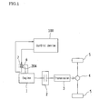
- FIGS. 1 to 8 show an embodiment of the present invention.
- the vehicle power train given as an example in this embodiment is of the front-engine rear-wheel drive (FR) type.
- Drive force generated by an engine 1 is input to a transmission 3 via a clutch 2 and then transmitted from the transmission 3 to left and right rear wheels 5 serving as drive wheels via a differential 4.
- the vehicle drive force generated by the engine 1 is controlled by a control device (ECU: electronic control unit) 100 that will be described later.
- ECU electronic control unit
- the amount of air drawn into the engine 1 is adjusted by an electronically-controlled throttle valve 6.
- the electronically-controlled throttle valve 6 is actuated by a throttle motor 7, and the throttle motor 7 is controlled by the control device 100.
- the control device 100 controls the throttle motor 7 so as to achieve a throttle opening degree (target throttle opening degree) for obtaining an optimum intake air amount (target air intake amount) according to operating conditions of the engine 1, such as an engine speed Ne detected by an engine speed sensor 205 and an accelerator opening degree (amount of depression of an accelerator pedal (not shown) by the driver) detected by an accelerator opening degree sensor 203.
- the electronically-controlled throttle valve 6 may be not only controlled so as to achieve a throttle opening degree corresponding to the accelerator opening degree, but may be also controlled so as to achieve a throttle opening degree that is independent from the accelerator opening degree.
- the throttle opening degree is controlled based on output from a throttle opening degree sensor 204.
- a clutch 2 is, for example, a publicly known dry-type single plate friction clutch, and although not shown, a release fork is actuated by a piston rod of a clutch actuator in response to a driver operation for depressing a clutch pedal (not shown), thus displacing a release bearing in the axial direction along an input shaft of the transmission 3 so as to put the clutch 2 in a forcefully sandwiched state (engaged state), a released state (disengaged state), or a sliding state (semi-engaged state).
- the disengaged or engaged state of the clutch 2 in response to a clutch pedal depression operation is recognized by the control device 100 based on an output signal from a clutch stroke sensor 201.
- the clutch stroke sensor 201 detects an electrical signal corresponding to the stroke amount of the piston rod of the clutch actuator and inputs the electrical signal to the control device 100.
- the transmission 3 has, for example, a configuration similar to that of a publicly known constant-mesh transmission having six forward gears and one reverse gear as selectable gears.
- a shift device 8 for manually performing gear shift operations on the transmission 3 is disposed in the vehicle interior.
- the shift device 8 includes a shift lever 81, a shift gate 82, a power transmission mechanism (not shown), and the like.
- the shift lever 81 is displaced in conformity with the shift gate 82.
- the shift gate 82 is of the so-called H pattern type and includes one selection groove 83, multiple (three here) forward shift grooves 84, 85, and 86, and one reverse shift groove 87.
- the one selection groove 83 is provided so as to extend linearly along the left-right direction (also called the vehicle width direction or the selection operation direction).
- the three forward shift grooves 84, 85, and 86 are provided so as to extend in the front-back direction (also called the vehicle front-back direction or shift operation direction) so as to orthogonally traverse the selection groove 83 at three places with predetermined gaps therebetween in the lengthwise direction of the selection groove 83.
- the one reverse shift groove 87 is provided so as to extend toward one side in the orthogonal direction (toward the front of the vehicle) from one end in the lengthwise direction of the selection groove 83.
- the power transmission mechanism transmits motion of the shift lever 81 to a synchronization mechanism (not shown) for switching gears with which the transmission 3 is equipped, and since the power transmission mechanism has a configuration similar to publicly known configurations, the description thereof given here will be brief.
- This power transmission mechanism can be, for example, a mechanism including cables or rods and links, and the like, or alternatively can be a shift actuator.
- this shift actuator is configured so as to include a detection element (switch, sensor, or the like) for detecting motion of the shift lever 81, and a motor or hydraulic cylinder whose operations are controlled by a control element (e.g., the control device 100 is appropriated) based on the input of an output signal from the detection element and that is for actuating the synchronization mechanism of the transmission 3.
- a detection element switch, sensor, or the like
- a motor or hydraulic cylinder whose operations are controlled by a control element (e.g., the control device 100 is appropriated) based on the input of an output signal from the detection element and that is for actuating the synchronization mechanism of the transmission 3.
- a selection operation is performed to displace the shift lever 81 in one direction in the selection groove 83 of the shift gate 82, and thereafter a shift operation is performed to displace the shift lever 81 in one direction in any of the shift grooves 84 to 87.
- the force of the selection operation and the force of the shift operation are transmitted via the power transmission mechanism to the synchronization mechanism of the transmission 3 so as to select an appropriate gear of the transmission 3.
- a gear-shift instruction device for notifying the driver of a target gear (gear position in the transmission 3) that is appropriate for the driving mode (e.g., a fuel consumption driving mode for fuel consumption improvement or the like, or a sports driving mode for sporty driving) in accordance with the vehicle driving condition.
- a target gear gear position in the transmission 3
- the driving mode e.g., a fuel consumption driving mode for fuel consumption improvement or the like, or a sports driving mode for sporty driving
- the gear-shift instruction device is configured so as to include an up-shift lamp 31 and a down-shift lamp 32 for allowing the driver to visually confirm the notifications, and the control device 100 for controlling the operation of the lamps 31 and 32, and the gear-shift instruction device will be described in detail below.
- the up-shift lamp 31 and the down-shift lamp 32 are provided in the center of a combination meter 10, for example.
- the combination meter 10 is disposed in front of the driver seat in the vehicle interior, includes a speedometer 11, a tachometer 12, a water temperature gauge 13, a fuel gauge 14, and the like, and although not given reference signs, the combination meter 10 further includes turn signal lamps, an odometer, a trip meter, various types of warning indicator lamps, and the like.
- the up-shift lamp 31 is lit or blinked when a request for up-shifting of the target gear of the transmission 3 is given, and the down-shift lamp 32 is lit or blinked when a request for down-shifting of the target gear of the transmission 3 is given.
- the up-shift lamp 31 and the down-shift lamp 32 are LEDs, for example, and the actuation (lighting or blinking) and stopping (extinguishing) thereof is controlled by the control device 100.
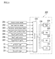
- the control device 100 is a generally known electronic control unit (ECU), and includes a CPU 101, a ROM 102, a RAM 103, a backup RAM 104, and the like.
- ECU electronice control unit
- the ROM 102 stores programs for executing control of the engine 1 related to basic driving of the vehicle, and also stores various types of program including a program for executing gear shift instruction control for notifying the driver of a target gear of the transmission 3 that is appropriate for the driving mode in accordance with the driving condition of the vehicle, and the like.
- the specific content of the gear shift instruction control will be described later.
- the CPU 101 executes arithmetic processing based on a map and the programs stored in the ROM 102.
- the RAM 103 is a memory for temporarily storing the results of arithmetic processing performed by the CPU 101, data received as input from various sensors, and the like
- the backup RAM 104 is a nonvolatile memory for storing, for example, data that is to be saved while the engine 1 is stopped.
- the CPU 101, the ROM 102, the RAM 103, and the backup RAM 104 are connected to each other and an interface 105 via a bus 106.
- Various types of sensors such as the following are connected to the interface 105, and also at least the up-shift lamp 31, the down-shift lamp 32, a lamp 33 for giving a notification of an unintentional shift change, and the like are connected to the interface 105.
- the sensors include at least the clutch stroke sensor 201, a gear position sensor 202 for detecting the gear that is selected in the transmission 3, the accelerator opening degree sensor 203, the throttle opening degree sensor 204, the engine speed sensor 205 for detecting the rotation speed of the crankshaft of the engine 1 (engine speed Ne), a wheel speed sensor 206 for detecting the vehicle speed, and an acceleration sensor 207 for detecting the forward/backward acceleration of the vehicle.
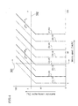
- the ROM 102 furthermore stores a gear shift map such as that shown in FIG. 4 .
- This gear shift map is a map that has the vehicle speed and the accelerator opening degree as parameters and is set with multiple regions for obtaining an optimum gear (target gear) in terms of improving fuel consumption in accordance with the vehicle speed and accelerator opening degree.
- the regions of the gear shift map are demarcated by gear shift lines (gear switching lines).
- gear shift lines are up-shift lines (solid lines) and down-shift lines (dashed-dotted lines).
- the switching directions and gears of up-shifts and down-shifts are indicated by arrows and numbers.
- unintentional shift changes that have been performed can be detected, and a history of the unintentional shift changes can be saved in a predetermined area in the RAM 103, the backup RAM 104, or the like.
- unintentional shift changes are shift changes that apply an excessive load to the vehicle power train (engine 1, transmission 3, differential 4, and the like). Also, relatively mild unintentional shift changes that apply a relatively mild load being applied to the vehicle power train are not detected.
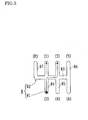
- FIG. 5 shows the case where when performing an up-shift for moving the shift lever 81 from the second gear position in the 1-2 shift groove 84 of the shift gate 82 to the third gear position in the adjacent 3-4 shift groove, the shift lever 81 is accidentally moved to the first gear position (see the dashed double-dotted line). In other words, this is the case of a down-shift to the first gear when attempting to perform an up-shift to the third gear while driving in the second gear.
- FIG. 6 shows the case where when performing a down-shift for moving the shift lever 81 from the fifth gear position in the 5-6 shift groove 86 of the shift gate 82 to the fourth gear position in the adjacent 3-4 shift groove 85, the shift lever 81 is accidentally moved to the second gear position in the 1-2 shift groove 84. In other words, this is the case of an overshifting down to the second gear when attempting to perform a down-shift to the fourth gear while driving in the fifth gear.
- FIG. 7 shows the case where when performing a down-shift for moving the shift lever 81 from the sixth gear position in the 5-6 shift groove 86 of the shift gate 82 to the fourth gear position in the adjacent 3-4 shift groove 85, the shift lever 81 is accidentally moved to the second gear position in the 1-2 shift groove 84. In other words, this is the case of an overshifting down to the second gear when attempting to perform a down-shift to the fourth gear while driving in the sixth gear.
- step S1 the current (actual) gear N of the transmission 3 is obtained based on the input of an output signal from the gear position sensor 202.
- a method of obtaining the current gear N it is possible to employ a method of determining the current gear N using the vehicle speed (output signal from the wheel speed sensor 206), the engine speed (output signal from the engine speed sensor 205), and the clutch state (output signal from the clutch stroke sensor 201).
- step S2 it is determined whether a gear shift is necessary.
- step S2 if a gear shift is not necessary, a negative determination is made in step S2, and the procedure returns to step S1. However, if a gear shift is necessary, an affirmative determination is made in step S2, and processing for notifying the driver of a request to shift to the target gear is executed in the subsequent step S3.
- step S2 in the case where the current gear N is "2" for example in FIG. 4 , if the vehicle speed rises from point A to point B, an up-shift gear shift line (2->3) is crossed, and therefore the target gear X becomes (N+1), that is to say, "3". In such a case, an affirmative determination is made in step S2, and the up-shift lamp 31 is actuated (lit or blinked) in step S3.
- step S2 the down-shift lamp 32 is operated (lit or blinked) in step S3.
- step S4 it is determined whether the current gear N of the transmission 3 matches the result obtained in step S1 based on a detection signal from the gear position sensor 202. Specifically, it is determined here whether the driver performed a shift change in a time lag period that is from when the gear shift instruction was given in step S3 to when the corresponding up-shift lamp 31 or down-shift lamp 32 was actually actuated.
- step S4 a negative determination is made in step S4, and the procedure returns to step S1.
- an affirmative determination is made in step S4, and the procedure moves to the subsequent step S5.
- step S5 it is determined whether the vehicle speed is greater than or equal to a predetermined threshold value (e.g., see a broken line 301 in FIG. 4 ) based on the input of an output signal from the wheel speed sensor 206.
- a predetermined threshold value e.g., see a broken line 301 in FIG. 4
- the degree of load that is applied to the vehicle power train when an unintentional shift change such as a down-shift when an up-shift is required is obtained by appropriate experimentation, simulation, or the like for each of various cases of unintentional shift changes, and the threshold value is set based on the obtained results.
- the vehicle will rapidly decelerate in the case where the vehicle speed becomes greater than or equal to the predetermined threshold value (e.g., see the broken line 301 in FIG. 4 ) when the accelerator opening degree is greater than or equal to a predetermined threshold value (e.g., see a broken line 302 in FIG. 4 ), that is to say, if a change occurs such that, among the four top, bottom, left, and right regions demarcated by the intersection of the broken lines 301 and 302 indicating the two threshold values, any of gear shift lines included in the top right region is crossed.
- the predetermined threshold value e.g., see the broken line 301 in FIG. 4
- a predetermined threshold value e.g., see a broken line 302 in FIG. 4
- step S5 a negative determination is made in step S5
- the procedure returns to step S1.
- the threshold value e.g., see the broken line 301 in FIG. 4
- an affirmative determination is made in step S5, and the procedure moves to the subsequent step S6.
- step S6 it is determined whether a shift change (i.e., a down-shift) was performed such that the current gear N becomes a gear (X-1) or (X-2) that is lower than the target gear X of which the driver was notified in step S3.
- a shift change i.e., a down-shift
- step S6 if this down-shift was not performed, a negative determination is made in step S6, and the procedure returns to step S1. However, in the case where the down-shift was performed, an affirmative determination is made in step S6, and the procedure moves to the subsequent step S7.
- step S7 it is determined whether the actual deceleration G (negative acceleration) of the vehicle is greater than or equal to a predetermined threshold value based on the input of an output signal from the acceleration sensor 207.
- the relationship between the vehicle deceleration G and the degree of load applied to the vehicle power train at that deceleration G is obtained through appropriate experimentation, simulation, or the like, and the threshold value is set based on the obtained results.
- step S7 if the actual deceleration G is less than the threshold value, a negative determination is made in step S7, and the procedure returns to step S1. However, in the case where the actual deceleration G is greater than or equal to the threshold value, an affirmative determination is made in step S7, and the procedure moves to the subsequent step S8.
- step S8 it is detected that an unintentional shift change was performed, notification processing is performed for actuating (lighting or blinking) the lamp 33 in order to notify the driver that the unintentional shift change occurred, and saving processing is performed for saving the unintentional shift change in a history in a predetermined area in the RAM 103, the backup RAM 104, or the like.
- the saving processing it is possible to retain a region for saving an unintentional shift change history in the RAM 103, the backup RAM 104, or the like in advance, and count up (increment) a counter each time an unintentional shift change is detected.
- the unintentional shift change in the exemplary case of an unintentional shift change that will subject the vehicle power train to excessive damage (e.g., a down-shift when an up-shift is required while at a predetermined vehicle speed or predetermined engine speed or higher, such that the vehicle rapidly decelerates), the unintentional shift change can be reliably detected, the driver can be notified of the unintentional shift change by actuating (lighting or blinking) the lamp 33, and the unintentional shift change can be saved in an unintentional shift change history in an appropriate memory.
- a down-shift when an up-shift is required while at a predetermined vehicle speed or predetermined engine speed or higher, such that the vehicle rapidly decelerates
- the unintentional shift change can be reliably detected, the driver can be notified of the unintentional shift change by actuating (lighting or blinking) the lamp 33, and the unintentional shift change can be saved in an unintentional shift change history in an appropriate memory.
- notifying the driver of an unintentional shift change enables the driver to be aware of the driver's driving state, and furthermore, by referencing the history of unintentional shift changes, a maintenance company or the like can find out the condition of vehicle use by the driver and become aware of the extent of the load that was applied to the vehicle power train.
- referencing the unintentional shift change history enables ascertaining the cause for producing the excessive load.
- vehicle speed or engine speed
- negative vehicle acceleration deceleration G
- deceleration G is added as a parameter for estimating the degree of load that will be applied to the power train due to an unintentional shift change, thus enabling improving reliability by, for example, raising performance in the detection of an unintentional shift change.
- control device 100 corresponds to an element for realizing the functions of elements recited in the claims.
- steps S1 to S3 correspond to the target notification unit recited in the claims
- steps S4 to S8 correspond to the detection unit recited in the claims.
- step S8 and the RAM 103 or the backup RAM 104 of the control device 100 correspond to the information saving unit recited in the claims
- step S8 corresponds to the notification unit and the processing unit recited in the claims
- step S5 corresponds to the driving condition determination unit recited in the claims
- step S6 corresponds to the gear shift operation determination unit recited in the claims
- step S7 corresponds to the rapid deceleration determination unit recited in the claims.
- the present invention is not limited to this. Although not shown, the present invention can also be applied to a vehicle having a front-engine, front-wheel drive (FF) type of power train, for example.
- FF front-wheel drive
- an MT (manual transmission) vehicle in which gears in the transmission 3 are changed by operations performed on the clutch pedal (not shown) and the shift lever 81 is described in the above embodiment, the present invention is not limited to this. Although not shown, the present invention can also be applied to an AMT (automated manual transmission) vehicle, for example.
- An AMT vehicle has a publicly known configuration in which, for example, the clutch pedal is omitted and the clutch 2 is actuated by an actuator, and an up-shift or a down-shift is performed on the transmission 3 in response to an operation for pushing the shift lever forward or an operation for pushing it backward.
- the present invention can be favorably applied to a gear-shift instruction device that notifies a driver of a target gear of a transmission in which the gear can be switched in response to a manual gear shift operation.
Landscapes
- Engineering & Computer Science (AREA)
- General Engineering & Computer Science (AREA)
- Mechanical Engineering (AREA)
- Control Of Transmission Device (AREA)
- Arrangement And Mounting Of Devices That Control Transmission Of Motive Force (AREA)
Applications Claiming Priority (1)
| Application Number | Priority Date | Filing Date | Title |
|---|---|---|---|
| PCT/JP2011/058428 WO2012137277A1 (fr) | 2011-04-01 | 2011-04-01 | Dispositif d'instruction de passage de rapport |
Publications (3)
| Publication Number | Publication Date |
|---|---|
| EP2602146A1 true EP2602146A1 (fr) | 2013-06-12 |
| EP2602146A4 EP2602146A4 (fr) | 2014-09-03 |
| EP2602146B1 EP2602146B1 (fr) | 2019-08-21 |
Family
ID=46968718
Family Applications (1)
| Application Number | Title | Priority Date | Filing Date |
|---|---|---|---|
| EP11847888.2A Active EP2602146B1 (fr) | 2011-04-01 | 2011-04-01 | Dispositif d'instruction de passage de rapport |
Country Status (3)
| Country | Link |
|---|---|
| EP (1) | EP2602146B1 (fr) |
| JP (1) | JP5267742B2 (fr) |
| WO (1) | WO2012137277A1 (fr) |
Families Citing this family (2)
| Publication number | Priority date | Publication date | Assignee | Title |
|---|---|---|---|---|
| CN102869528B (zh) * | 2010-04-28 | 2015-09-23 | 丰田自动车株式会社 | 车辆的变速指示系统 |
| JP7375520B2 (ja) * | 2019-12-18 | 2023-11-08 | スズキ株式会社 | アイドリングストップ車両の報知装置 |
Family Cites Families (7)
| Publication number | Priority date | Publication date | Assignee | Title |
|---|---|---|---|---|
| JPS6116144A (ja) * | 1984-06-29 | 1986-01-24 | Fujitsu Ten Ltd | 異常シフト警報装置 |
| JP3655466B2 (ja) * | 1998-04-24 | 2005-06-02 | 富士重工業株式会社 | 自動変速装置の変速段位置表示装置 |
| JP2005306242A (ja) * | 2004-04-22 | 2005-11-04 | Hino Motors Ltd | 変速指示装置 |
| JP4274224B2 (ja) * | 2006-10-13 | 2009-06-03 | トヨタ自動車株式会社 | 自動車の変速指示装置 |
| JP2008121701A (ja) | 2006-11-08 | 2008-05-29 | Toyota Motor Corp | 変速指示装置 |
| JP5386777B2 (ja) * | 2006-12-05 | 2014-01-15 | マツダ株式会社 | 自動変速機付き車両の報知装置 |
| JP2010185536A (ja) | 2009-02-13 | 2010-08-26 | Toyota Motor Corp | 変速機のミスシフト防止機構 |
-
2011
- 2011-04-01 WO PCT/JP2011/058428 patent/WO2012137277A1/fr not_active Ceased
- 2011-04-01 JP JP2012527133A patent/JP5267742B2/ja not_active Expired - Fee Related
- 2011-04-01 EP EP11847888.2A patent/EP2602146B1/fr active Active
Also Published As
| Publication number | Publication date |
|---|---|
| JP5267742B2 (ja) | 2013-08-21 |
| EP2602146A4 (fr) | 2014-09-03 |
| WO2012137277A1 (fr) | 2012-10-11 |
| JPWO2012137277A1 (ja) | 2014-07-28 |
| EP2602146B1 (fr) | 2019-08-21 |
Similar Documents
| Publication | Publication Date | Title |
|---|---|---|
| US8556772B2 (en) | Manual transmission clutch protection apparatus | |
| JP4952221B2 (ja) | 手動変速機のギヤ位置判定装置及び自動車の変速指示装置 | |
| US20110043348A1 (en) | Shift Prompt System | |
| EP0291183A2 (fr) | Affichage et indicateur de panne pour commande semi-automatique d'une transmission mécanique | |
| US20150012194A1 (en) | Method for operating a manual transmission in a motor vehicle | |
| JP2009047216A (ja) | 車両用変速機の変速制御装置 | |
| EP1944529B1 (fr) | Appareil de détermination de vitesse, procédé de détermination de vitesse, appareil d'instruction de changement de vitesses, et procédé d'instruction de changement de vitesses | |
| JP2009085328A (ja) | 車両の制御装置 | |
| EP2602146B1 (fr) | Dispositif d'instruction de passage de rapport | |
| JP5958698B2 (ja) | 自動変速機の変速制御装置 | |
| KR101646127B1 (ko) | 차량용 변속 제어 장치 및 방법 | |
| EP1921353B1 (fr) | Dispositif d'instruction de levier de vitesse et procédé d'instruction de levier de vitesse | |
| JP4687164B2 (ja) | 変速機の制御装置 | |
| JP2006321364A (ja) | 車両の運転状態表示装置及び車両の運転状態表示方法 | |
| US9540009B2 (en) | Transmission system for vehicle | |
| JP2008128438A (ja) | 変速機のシフト制御装置 | |
| JP4999874B2 (ja) | 自動変速機の制御装置 | |
| JP2016210376A (ja) | 車両の変速指示装置 | |
| JP2011117500A (ja) | クラッチスイッチの異常判定装置 | |
| JP4946797B2 (ja) | 同期噛み合い式変速機の変速操作装置 | |
| JP4513846B2 (ja) | 自動車の変速指示装置 | |
| JP6213721B2 (ja) | 自動変速機の制御装置 | |
| JP2014163393A (ja) | 車両の制御装置 | |
| JP6213276B2 (ja) | 変速制御装置 | |
| JP6410017B2 (ja) | 自動変速制御装置 |
Legal Events
| Date | Code | Title | Description |
|---|---|---|---|
| PUAI | Public reference made under article 153(3) epc to a published international application that has entered the european phase |
Free format text: ORIGINAL CODE: 0009012 |
|
| 17P | Request for examination filed |
Effective date: 20120619 |
|
| AK | Designated contracting states |
Kind code of ref document: A1 Designated state(s): AL AT BE BG CH CY CZ DE DK EE ES FI FR GB GR HR HU IE IS IT LI LT LU LV MC MK MT NL NO PL PT RO RS SE SI SK SM TR |
|
| RIN1 | Information on inventor provided before grant (corrected) |
Inventor name: SHIMIZU, KENJI Inventor name: ITO, MITSUHARU |
|
| DAX | Request for extension of the european patent (deleted) | ||
| A4 | Supplementary search report drawn up and despatched |
Effective date: 20140806 |
|
| RIC1 | Information provided on ipc code assigned before grant |
Ipc: F16H 61/02 20060101AFI20140731BHEP Ipc: B60K 23/00 20060101ALN20140731BHEP Ipc: F16H 63/42 20060101ALN20140731BHEP Ipc: F16H 61/12 20100101ALN20140731BHEP |
|
| REG | Reference to a national code |
Ref country code: DE Ref legal event code: R079 Ref document number: 602011061509 Country of ref document: DE Free format text: PREVIOUS MAIN CLASS: B60K0023000000 Ipc: F16H0061020000 |
|
| GRAP | Despatch of communication of intention to grant a patent |
Free format text: ORIGINAL CODE: EPIDOSNIGR1 |
|
| RIC1 | Information provided on ipc code assigned before grant |
Ipc: F16H 61/12 20100101ALN20190212BHEP Ipc: F16H 61/02 20060101AFI20190212BHEP Ipc: B60K 23/00 20060101ALN20190212BHEP Ipc: F16H 63/42 20060101ALN20190212BHEP |
|
| STAA | Information on the status of an ep patent application or granted ep patent |
Free format text: STATUS: GRANT OF PATENT IS INTENDED |
|
| INTG | Intention to grant announced |
Effective date: 20190321 |
|
| GRAS | Grant fee paid |
Free format text: ORIGINAL CODE: EPIDOSNIGR3 |
|
| GRAA | (expected) grant |
Free format text: ORIGINAL CODE: 0009210 |
|
| STAA | Information on the status of an ep patent application or granted ep patent |
Free format text: STATUS: THE PATENT HAS BEEN GRANTED |
|
| AK | Designated contracting states |
Kind code of ref document: B1 Designated state(s): AL AT BE BG CH CY CZ DE DK EE ES FI FR GB GR HR HU IE IS IT LI LT LU LV MC MK MT NL NO PL PT RO RS SE SI SK SM TR |
|
| REG | Reference to a national code |
Ref country code: GB Ref legal event code: FG4D |
|
| REG | Reference to a national code |
Ref country code: CH Ref legal event code: EP |
|
| REG | Reference to a national code |
Ref country code: DE Ref legal event code: R096 Ref document number: 602011061509 Country of ref document: DE |
|
| REG | Reference to a national code |
Ref country code: AT Ref legal event code: REF Ref document number: 1170137 Country of ref document: AT Kind code of ref document: T Effective date: 20190915 |
|
| REG | Reference to a national code |
Ref country code: IE Ref legal event code: FG4D |
|
| REG | Reference to a national code |
Ref country code: DE Ref legal event code: R084 Ref document number: 602011061509 Country of ref document: DE |
|
| REG | Reference to a national code |
Ref country code: LT Ref legal event code: MG4D |
|
| REG | Reference to a national code |
Ref country code: NL Ref legal event code: MP Effective date: 20190821 |
|
| PG25 | Lapsed in a contracting state [announced via postgrant information from national office to epo] |
Ref country code: FI Free format text: LAPSE BECAUSE OF FAILURE TO SUBMIT A TRANSLATION OF THE DESCRIPTION OR TO PAY THE FEE WITHIN THE PRESCRIBED TIME-LIMIT Effective date: 20190821 Ref country code: LT Free format text: LAPSE BECAUSE OF FAILURE TO SUBMIT A TRANSLATION OF THE DESCRIPTION OR TO PAY THE FEE WITHIN THE PRESCRIBED TIME-LIMIT Effective date: 20190821 Ref country code: NL Free format text: LAPSE BECAUSE OF FAILURE TO SUBMIT A TRANSLATION OF THE DESCRIPTION OR TO PAY THE FEE WITHIN THE PRESCRIBED TIME-LIMIT Effective date: 20190821 Ref country code: BG Free format text: LAPSE BECAUSE OF FAILURE TO SUBMIT A TRANSLATION OF THE DESCRIPTION OR TO PAY THE FEE WITHIN THE PRESCRIBED TIME-LIMIT Effective date: 20191121 Ref country code: PT Free format text: LAPSE BECAUSE OF FAILURE TO SUBMIT A TRANSLATION OF THE DESCRIPTION OR TO PAY THE FEE WITHIN THE PRESCRIBED TIME-LIMIT Effective date: 20191223 Ref country code: NO Free format text: LAPSE BECAUSE OF FAILURE TO SUBMIT A TRANSLATION OF THE DESCRIPTION OR TO PAY THE FEE WITHIN THE PRESCRIBED TIME-LIMIT Effective date: 20191121 Ref country code: HR Free format text: LAPSE BECAUSE OF FAILURE TO SUBMIT A TRANSLATION OF THE DESCRIPTION OR TO PAY THE FEE WITHIN THE PRESCRIBED TIME-LIMIT Effective date: 20190821 Ref country code: SE Free format text: LAPSE BECAUSE OF FAILURE TO SUBMIT A TRANSLATION OF THE DESCRIPTION OR TO PAY THE FEE WITHIN THE PRESCRIBED TIME-LIMIT Effective date: 20190821 |
|
| PG25 | Lapsed in a contracting state [announced via postgrant information from national office to epo] |
Ref country code: IS Free format text: LAPSE BECAUSE OF FAILURE TO SUBMIT A TRANSLATION OF THE DESCRIPTION OR TO PAY THE FEE WITHIN THE PRESCRIBED TIME-LIMIT Effective date: 20191221 Ref country code: RS Free format text: LAPSE BECAUSE OF FAILURE TO SUBMIT A TRANSLATION OF THE DESCRIPTION OR TO PAY THE FEE WITHIN THE PRESCRIBED TIME-LIMIT Effective date: 20190821 Ref country code: GR Free format text: LAPSE BECAUSE OF FAILURE TO SUBMIT A TRANSLATION OF THE DESCRIPTION OR TO PAY THE FEE WITHIN THE PRESCRIBED TIME-LIMIT Effective date: 20191122 Ref country code: ES Free format text: LAPSE BECAUSE OF FAILURE TO SUBMIT A TRANSLATION OF THE DESCRIPTION OR TO PAY THE FEE WITHIN THE PRESCRIBED TIME-LIMIT Effective date: 20190821 Ref country code: LV Free format text: LAPSE BECAUSE OF FAILURE TO SUBMIT A TRANSLATION OF THE DESCRIPTION OR TO PAY THE FEE WITHIN THE PRESCRIBED TIME-LIMIT Effective date: 20190821 Ref country code: AL Free format text: LAPSE BECAUSE OF FAILURE TO SUBMIT A TRANSLATION OF THE DESCRIPTION OR TO PAY THE FEE WITHIN THE PRESCRIBED TIME-LIMIT Effective date: 20190821 |
|
| REG | Reference to a national code |
Ref country code: AT Ref legal event code: MK05 Ref document number: 1170137 Country of ref document: AT Kind code of ref document: T Effective date: 20190821 |
|
| PG25 | Lapsed in a contracting state [announced via postgrant information from national office to epo] |
Ref country code: TR Free format text: LAPSE BECAUSE OF FAILURE TO SUBMIT A TRANSLATION OF THE DESCRIPTION OR TO PAY THE FEE WITHIN THE PRESCRIBED TIME-LIMIT Effective date: 20190821 |
|
| PG25 | Lapsed in a contracting state [announced via postgrant information from national office to epo] |
Ref country code: EE Free format text: LAPSE BECAUSE OF FAILURE TO SUBMIT A TRANSLATION OF THE DESCRIPTION OR TO PAY THE FEE WITHIN THE PRESCRIBED TIME-LIMIT Effective date: 20190821 Ref country code: PL Free format text: LAPSE BECAUSE OF FAILURE TO SUBMIT A TRANSLATION OF THE DESCRIPTION OR TO PAY THE FEE WITHIN THE PRESCRIBED TIME-LIMIT Effective date: 20190821 Ref country code: AT Free format text: LAPSE BECAUSE OF FAILURE TO SUBMIT A TRANSLATION OF THE DESCRIPTION OR TO PAY THE FEE WITHIN THE PRESCRIBED TIME-LIMIT Effective date: 20190821 Ref country code: IT Free format text: LAPSE BECAUSE OF FAILURE TO SUBMIT A TRANSLATION OF THE DESCRIPTION OR TO PAY THE FEE WITHIN THE PRESCRIBED TIME-LIMIT Effective date: 20190821 Ref country code: DK Free format text: LAPSE BECAUSE OF FAILURE TO SUBMIT A TRANSLATION OF THE DESCRIPTION OR TO PAY THE FEE WITHIN THE PRESCRIBED TIME-LIMIT Effective date: 20190821 Ref country code: RO Free format text: LAPSE BECAUSE OF FAILURE TO SUBMIT A TRANSLATION OF THE DESCRIPTION OR TO PAY THE FEE WITHIN THE PRESCRIBED TIME-LIMIT Effective date: 20190821 |
|
| PG25 | Lapsed in a contracting state [announced via postgrant information from national office to epo] |
Ref country code: SK Free format text: LAPSE BECAUSE OF FAILURE TO SUBMIT A TRANSLATION OF THE DESCRIPTION OR TO PAY THE FEE WITHIN THE PRESCRIBED TIME-LIMIT Effective date: 20190821 Ref country code: CZ Free format text: LAPSE BECAUSE OF FAILURE TO SUBMIT A TRANSLATION OF THE DESCRIPTION OR TO PAY THE FEE WITHIN THE PRESCRIBED TIME-LIMIT Effective date: 20190821 Ref country code: IS Free format text: LAPSE BECAUSE OF FAILURE TO SUBMIT A TRANSLATION OF THE DESCRIPTION OR TO PAY THE FEE WITHIN THE PRESCRIBED TIME-LIMIT Effective date: 20200224 Ref country code: SM Free format text: LAPSE BECAUSE OF FAILURE TO SUBMIT A TRANSLATION OF THE DESCRIPTION OR TO PAY THE FEE WITHIN THE PRESCRIBED TIME-LIMIT Effective date: 20190821 |
|
| REG | Reference to a national code |
Ref country code: DE Ref legal event code: R097 Ref document number: 602011061509 Country of ref document: DE |
|
| PLBE | No opposition filed within time limit |
Free format text: ORIGINAL CODE: 0009261 |
|
| STAA | Information on the status of an ep patent application or granted ep patent |
Free format text: STATUS: NO OPPOSITION FILED WITHIN TIME LIMIT |
|
| PG2D | Information on lapse in contracting state deleted |
Ref country code: IS |
|
| 26N | No opposition filed |
Effective date: 20200603 |
|
| PG25 | Lapsed in a contracting state [announced via postgrant information from national office to epo] |
Ref country code: SI Free format text: LAPSE BECAUSE OF FAILURE TO SUBMIT A TRANSLATION OF THE DESCRIPTION OR TO PAY THE FEE WITHIN THE PRESCRIBED TIME-LIMIT Effective date: 20190821 |
|
| PG25 | Lapsed in a contracting state [announced via postgrant information from national office to epo] |
Ref country code: MC Free format text: LAPSE BECAUSE OF FAILURE TO SUBMIT A TRANSLATION OF THE DESCRIPTION OR TO PAY THE FEE WITHIN THE PRESCRIBED TIME-LIMIT Effective date: 20190821 |
|
| REG | Reference to a national code |
Ref country code: CH Ref legal event code: PL |
|
| PG25 | Lapsed in a contracting state [announced via postgrant information from national office to epo] |
Ref country code: FR Free format text: LAPSE BECAUSE OF NON-PAYMENT OF DUE FEES Effective date: 20200430 Ref country code: LU Free format text: LAPSE BECAUSE OF NON-PAYMENT OF DUE FEES Effective date: 20200401 Ref country code: CH Free format text: LAPSE BECAUSE OF NON-PAYMENT OF DUE FEES Effective date: 20200430 Ref country code: LI Free format text: LAPSE BECAUSE OF NON-PAYMENT OF DUE FEES Effective date: 20200430 |
|
| REG | Reference to a national code |
Ref country code: BE Ref legal event code: MM Effective date: 20200430 |
|
| PG25 | Lapsed in a contracting state [announced via postgrant information from national office to epo] |
Ref country code: BE Free format text: LAPSE BECAUSE OF NON-PAYMENT OF DUE FEES Effective date: 20200430 |
|
| GBPC | Gb: european patent ceased through non-payment of renewal fee |
Effective date: 20200401 |
|
| PG25 | Lapsed in a contracting state [announced via postgrant information from national office to epo] |
Ref country code: IE Free format text: LAPSE BECAUSE OF NON-PAYMENT OF DUE FEES Effective date: 20200401 Ref country code: GB Free format text: LAPSE BECAUSE OF NON-PAYMENT OF DUE FEES Effective date: 20200401 |
|
| PGFP | Annual fee paid to national office [announced via postgrant information from national office to epo] |
Ref country code: DE Payment date: 20210316 Year of fee payment: 11 |
|
| PG25 | Lapsed in a contracting state [announced via postgrant information from national office to epo] |
Ref country code: MT Free format text: LAPSE BECAUSE OF FAILURE TO SUBMIT A TRANSLATION OF THE DESCRIPTION OR TO PAY THE FEE WITHIN THE PRESCRIBED TIME-LIMIT Effective date: 20190821 Ref country code: CY Free format text: LAPSE BECAUSE OF FAILURE TO SUBMIT A TRANSLATION OF THE DESCRIPTION OR TO PAY THE FEE WITHIN THE PRESCRIBED TIME-LIMIT Effective date: 20190821 |
|
| PG25 | Lapsed in a contracting state [announced via postgrant information from national office to epo] |
Ref country code: MK Free format text: LAPSE BECAUSE OF FAILURE TO SUBMIT A TRANSLATION OF THE DESCRIPTION OR TO PAY THE FEE WITHIN THE PRESCRIBED TIME-LIMIT Effective date: 20190821 |
|
| REG | Reference to a national code |
Ref country code: DE Ref legal event code: R119 Ref document number: 602011061509 Country of ref document: DE |
|
| PG25 | Lapsed in a contracting state [announced via postgrant information from national office to epo] |
Ref country code: DE Free format text: LAPSE BECAUSE OF NON-PAYMENT OF DUE FEES Effective date: 20221103 |