EP2602521A2 - Öffnungsmechanismus eines Hochleistungsentladungsventils für Brand- und Explosionsschutz - Google Patents
Öffnungsmechanismus eines Hochleistungsentladungsventils für Brand- und Explosionsschutz Download PDFInfo
- Publication number
- EP2602521A2 EP2602521A2 EP12195483.8A EP12195483A EP2602521A2 EP 2602521 A2 EP2602521 A2 EP 2602521A2 EP 12195483 A EP12195483 A EP 12195483A EP 2602521 A2 EP2602521 A2 EP 2602521A2
- Authority
- EP
- European Patent Office
- Prior art keywords
- valve
- links
- actuation mechanism
- poppet
- valve member
- Prior art date
- Legal status (The legal status is an assumption and is not a legal conclusion. Google has not performed a legal analysis and makes no representation as to the accuracy of the status listed.)
- Granted
Links
Images


Classifications
-
- A—HUMAN NECESSITIES
- A62—LIFE-SAVING; FIRE-FIGHTING
- A62C—FIRE-FIGHTING
- A62C13/00—Portable extinguishers which are permanently pressurised or pressurised immediately before use
- A62C13/62—Portable extinguishers which are permanently pressurised or pressurised immediately before use with a single permanently pressurised container
- A62C13/64—Portable extinguishers which are permanently pressurised or pressurised immediately before use with a single permanently pressurised container the extinguishing material being released by means of a valve
-
- A—HUMAN NECESSITIES
- A62—LIFE-SAVING; FIRE-FIGHTING
- A62C—FIRE-FIGHTING
- A62C37/00—Control of fire-fighting equipment
- A62C37/36—Control of fire-fighting equipment an actuating signal being generated by a sensor separate from an outlet device
- A62C37/38—Control of fire-fighting equipment an actuating signal being generated by a sensor separate from an outlet device by both sensor and actuator, e.g. valve, being in the danger zone
-
- F—MECHANICAL ENGINEERING; LIGHTING; HEATING; WEAPONS; BLASTING
- F16—ENGINEERING ELEMENTS AND UNITS; GENERAL MEASURES FOR PRODUCING AND MAINTAINING EFFECTIVE FUNCTIONING OF MACHINES OR INSTALLATIONS; THERMAL INSULATION IN GENERAL
- F16K—VALVES; TAPS; COCKS; ACTUATING-FLOATS; DEVICES FOR VENTING OR AERATING
- F16K31/00—Actuating devices; Operating means; Releasing devices
- F16K31/003—Actuating devices; Operating means; Releasing devices operated without a stable intermediate position, e.g. with snap action
-
- A—HUMAN NECESSITIES
- A62—LIFE-SAVING; FIRE-FIGHTING
- A62C—FIRE-FIGHTING
- A62C3/00—Fire prevention, containment or extinguishing specially adapted for particular objects or places
- A62C3/07—Fire prevention, containment or extinguishing specially adapted for particular objects or places in vehicles, e.g. in road vehicles
-
- A—HUMAN NECESSITIES
- A62—LIFE-SAVING; FIRE-FIGHTING
- A62C—FIRE-FIGHTING
- A62C37/00—Control of fire-fighting equipment
- A62C37/08—Control of fire-fighting equipment comprising an outlet device containing a sensor, or itself being the sensor, i.e. self-contained sprinklers
- A62C37/10—Releasing means, e.g. electrically released
-
- F—MECHANICAL ENGINEERING; LIGHTING; HEATING; WEAPONS; BLASTING
- F16—ENGINEERING ELEMENTS AND UNITS; GENERAL MEASURES FOR PRODUCING AND MAINTAINING EFFECTIVE FUNCTIONING OF MACHINES OR INSTALLATIONS; THERMAL INSULATION IN GENERAL
- F16K—VALVES; TAPS; COCKS; ACTUATING-FLOATS; DEVICES FOR VENTING OR AERATING
- F16K31/00—Actuating devices; Operating means; Releasing devices
- F16K31/02—Actuating devices; Operating means; Releasing devices electric; magnetic
- F16K31/025—Actuating devices; Operating means; Releasing devices electric; magnetic actuated by thermo-electric means
-
- F—MECHANICAL ENGINEERING; LIGHTING; HEATING; WEAPONS; BLASTING
- F16—ENGINEERING ELEMENTS AND UNITS; GENERAL MEASURES FOR PRODUCING AND MAINTAINING EFFECTIVE FUNCTIONING OF MACHINES OR INSTALLATIONS; THERMAL INSULATION IN GENERAL
- F16K—VALVES; TAPS; COCKS; ACTUATING-FLOATS; DEVICES FOR VENTING OR AERATING
- F16K31/00—Actuating devices; Operating means; Releasing devices
- F16K31/44—Mechanical actuating means
-
- A—HUMAN NECESSITIES
- A62—LIFE-SAVING; FIRE-FIGHTING
- A62C—FIRE-FIGHTING
- A62C35/00—Permanently-installed equipment
- A62C35/58—Pipe-line systems
- A62C35/68—Details, e.g. of pipes or valve systems
-
- Y—GENERAL TAGGING OF NEW TECHNOLOGICAL DEVELOPMENTS; GENERAL TAGGING OF CROSS-SECTIONAL TECHNOLOGIES SPANNING OVER SEVERAL SECTIONS OF THE IPC; TECHNICAL SUBJECTS COVERED BY FORMER USPC CROSS-REFERENCE ART COLLECTIONS [XRACs] AND DIGESTS
- Y10—TECHNICAL SUBJECTS COVERED BY FORMER USPC
- Y10T—TECHNICAL SUBJECTS COVERED BY FORMER US CLASSIFICATION
- Y10T137/00—Fluid handling
- Y10T137/1624—Destructible or deformable element controlled
- Y10T137/1632—Destructible element
- Y10T137/1647—Explosive actuation
-
- Y—GENERAL TAGGING OF NEW TECHNOLOGICAL DEVELOPMENTS; GENERAL TAGGING OF CROSS-SECTIONAL TECHNOLOGIES SPANNING OVER SEVERAL SECTIONS OF THE IPC; TECHNICAL SUBJECTS COVERED BY FORMER USPC CROSS-REFERENCE ART COLLECTIONS [XRACs] AND DIGESTS
- Y10—TECHNICAL SUBJECTS COVERED BY FORMER USPC
- Y10T—TECHNICAL SUBJECTS COVERED BY FORMER US CLASSIFICATION
- Y10T137/00—Fluid handling
- Y10T137/7722—Line condition change responsive valves
- Y10T137/7734—Fluid opened valve requiring reset
Definitions
- This invention relates to a method of and apparatus for the discharge of one or more fire extinguishing agent(s). More particularly, the invention relates to a valve opening mechanism suited to the rapid discharge of fire extinguishing agent(s) and other high mass flow applications.
- the invention refers to an apparatus used to rapidly disperse extinguishing agents within a confined space such as the crew compartment of a military vehicle following a fire or explosion event.
- AFES automatic fire extinguishing systems
- IR infrared
- UV ultra violet
- the systems comprise a cylinder filled with extinguishing agent, a fast acting valve and a nozzle which enables rapid and efficient deployment of agent throughout the vehicle.
- the rapid discharge of a fire extinguishing agent into confined areas of vehicles subsequent to an incident is known to suppress the adverse effects experienced by the personnel within the vehicle to survivable levels.
- Some of the criteria used to determine a survivable event include extinguishing the flame and preventing re-flashing; a reduction in temperature to prevent greater than second degree burns; and the realization of safe levels (i.e. levels up to which personnel can continue to carry out their duties) of overpressure, acid gas, oxygen and concentration of fire extinguishing agent within the vehicle.
- a known apparatus for fire extinguishing in such circumstances comprises a generally cylindrical canister which contains a fire extinguishing agent which is pressurized by a gas such as nitrogen.
- the fire extinguishant agent must be applied rapidly.
- the outlet for the extinguishant from the canister is typically positioned at the base of the cylinder.
- a high rate discharge (HRD) valve is operated to allow the discharge of the extinguishing agent.
- the opening of the valve allows the nitrogen to expand, pushing the extinguishant between it and the valve out through the valve.
- the orientation of the canister and the location of the outlet in the cylinder allow a high proportion of the extinguishing agent to be discharged rapidly (because the extinguishing agent will be pushed out of the outlet by the nitrogen adjacent the extinguishing agent).
- a valve actuation mechanism has a plurality of links. Each link has a proximal end and distal end, and the links are disposed adjacent a valve member.
- the actuation mechanism also has at least one roller connected to the distal ends of at least two links. The roller contacts a surface of the valve member.
- at least one pivot for each link is present in the valve, wherein each pivot is positioned on the proximal end of each of the plurality of links.
- a high speed valve has a valve body having a flow passage therethrough and a poppet disposed within the valve body.
- the poppet is movable between a first position in which the poppet blocks the flow passage and a second position.
- the poppet containing a piston connected to a stem at a proximal end of the stem.
- the valve also has a pivotal link actuation mechanism adjacent a distal end of the stem.
- a fire suppression system has a pressure container for holding a fire suppression material that is connected to a high speed valve.
- the high speed valve has a valve body having a flow passage therethrough and a poppet disposed within the valve body.
- the poppet is movable between a first position in which the poppet blocks the flow passage and a second position.
- the poppet containing a piston connected to a stem at a proximal end of the stem.
- the valve also has a pivotal link actuation mechanism adjacent a distal end of the stem.
- the system also has a conduit connected to the flow passage of the valve, a nozzle for dispersing the fire suppression material upon opening of the high speed valve.
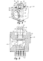
- FIG. 1 is a perspective view of a prior art apparatus for the discharge of a fire extinguishing agent.
- FIG. 2 is a perspective view of a prior art high rate discharge (HRD) valve.
- HRD high rate discharge
- FIG. 3A is a cross-sectional view of the prior art HRD valve in the closed position.
- FIG. 3B is a cross-sectional view of the prior art HRD valve in the open position.
- FIG. 4 is a perspective view of an HRD valve with a pivotal-link actuation mechanism.
- FIG. 5 is a cross-sectional view of the HRD valve with pivotal-link actuation mechanism.
- FIG. 6 is an elevation view of the pivotal link actuation mechanism.
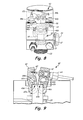
- FIG. 7 is a perspective view of another embodiment of an HRD valve.
- FIG. 8 is another perspective view of the HRD valve.
- FIG. 9 is an elevation view of another embodiment of the pivotal-link actuation mechanism.
- FIG. 10 is a cross-sectional view of yet another embodiment of the HRD valve.
- apparatus 11 for the discharge of a fire extinguishing agent is shown in FIGS. 1 - 3B .
- apparatus 11 comprises a generally cylindrical canister 12 and a releasing mechanism 13, such as a valve assembly 14 including high rate discharge (HRD) valve 15.
- HRD high rate discharge
- the releasing mechanism 13 is opened by solenoid actuator 16.
- a predetermined mass of fire extinguishing agent is added to the canister 12, which is then super-pressurized with nitrogen.
- Canister 12 is made from steel or a similarly high strength, rigid material to contain the pressurized extinguishing agent.
- the fire extinguishing agent discharges from the canister 12 in a fraction of a second.
- Canister 12 is usually fitted vertically (that is with its longitudinal axis extending vertically), or as close to vertical as possible, within an enclosed or confined area of a vehicle.
- an outlet nozzle 17 needs to be extended to the highest point thereof, such as where the walls meet the roof. This is achieved in the apparatus 11 by connecting the nozzle 17 to the releasing mechanism 13 via conduit 18, such an appropriate length of hose or pipe.
- the vertical orientation of the canister 12 allows releasing mechanism 13 at the outlet of canister 12 to be located at the lowest point.
- the fire extinguishant lies at the base of canister 12 (due to its relatively high density), with the nitrogen or a similar fluid pressurizing the space above.
- the pressurizing fluid expands and rapidly forces the extinguishant through HRD valve 15, along conduit 18 and out of nozzle 17.
- FIG. 2 is a perspective view of a prior art high rate discharge (HRD) valve 15 of valve assembly 14 that also includes release mechanism 13 and solenoid 16.
- Valve 15 contains hollow body 20 with an elongate bore on a vertical axis that terminates with an opening that forms inlet 22. Hollow body 20 has an enlarged central cavity (as seen in FIGS. 3A and 3B ) that communicates laterally with discharge outlet 24.
- the body of valve 15 is constructed from a metal alloy, or similarly rigid material.
- Valve 15 also contains mechanical override 26, as well as solenoid 16 for actuating the internal regulating mechanisms of valve 15.
- FIGS. 3A and 3B illustrate the internal workings of valve 15.
- the main operating and regulating mechanism of valve 15 is poppet 30.
- Poppet 30 is used to close the entrance to an opening in the body of valve 15.
- Poppet 30 contains a piston 31 at proximate end 34, connected to stem 35 that terminates at distal end 36 adjacent actuating mechanisms, such as mechanical override release mechanism 13 and solenoid 16.
- Poppet 30 is constructed from a material the same as or similar to that of body 20 of valve 15.
- Poppet 30 and stem 35 may be of various geometries, such as circular, oval, or polygonal in cross section so long as they match corresponding valve structures, such as the bore opening of inlet 22.
- poppet 30 is generally cylindrical, as is stem 35 that is centrally aligned with poppet 30.
- One or more annular grooves in piston 31 contain o-rings 32 which compress against the bore of valve 15, providing a seal.
- O-rings 32 are fabricated from rubber, or a similar elastomeric polymer capable of creating an air-tight seal between poppet 30 and body 20.
- Pressure inside canister 12 (illustrated in FIG. 1 ) pushes against proximate end 34 of poppet 30, forcing poppet 30 upward while constraining seals 32 against inlet 22 and canister 12.
- An elastomeric bumper 38 quiets the operation and prevents damage to poppet 30 and valve body 20.
- valve body 20 and poppet 30 slides to the open position allowing pressurized fluid, such as a fire extinguishant, to flow out of outlet 24.
- pressurized fluid such as a fire extinguishant
- FIGS. 4 to 10 illustrate release mechanisms for valve 15 in accordance with the present invention.
- FIG. 4 is a perspective view of HRD valve 15 with a pivotal-link actuation mechanism 40
- FIG. 5 is a cross-sectional view of HRD valve 15 with pivotal-link actuation mechanism 40.
- Valve 15 contains body 20 with a hollow cavity creating communication between inlet 22 and outlet 24, poppet 30 with piston 31, O-rings 32, and stem 35, and bumper 38 that have all been previously described.
- Poppet 30 is restrained by pivotal link actuation mechanism 40, which has links 42a-42b, rollers 44a and 44b, and pivots 46a-46b.
- links are flat plate structures with rounded tops and bottoms, and are made from metal.
- the top and bottom of links 42 contain holes that allow for the attachment of rollers 44 between adjacent links, as well as attachment to pivots 46.
- Rollers 44 are cylindrical metal rods that extend between adjacent links and are capable of rotation therebetween, forming what is a structure similar to a roller chain.
- Pivots 46 are short pieced of metal rods attached to body 20 of valve 15. In alternate embodiments, pivots may be machined directly into body 20 during manufacture of valve 15. In the closed position, poppet 30 is constrained vertically by the sets of pivoting links 42 and rollers 44 that contact top surface 48 of stem 35. Links 42 also contact each other in the over-center position. Gap 49 in body 20 of valve 15 allows for the movement of pivotal-link actuation mechanism 40. Gap 49 is a cutout in body 20 that will vary in dimension with differing embodiments, and will be dependent on space requirements for actuation of pivotal-link actuation mechanism 40.
- FIG. 6 illustrates pivotal link actuation mechanism 40 in operation where the links have been separated, i.e. pivoted, to a point close to allow stem 35 vertical motion.
- FIG. 7 is a view of another embodiment of pivotal link actuation mechanism 40 for HRD valve 15.
- poppet 30 is restrained by pivotal link actuation mechanism 40, which has links 42, rollers 44, and pivots 46 (not shown in this view).
- Stem 35 contains wedge 50 on the exterior of distal end 36, and an electrically actuated rod 52 contained within the interior that acts as a protractor pin.
- links 46 are pushed apart from the center of stem 35 using wedge 50, which is a taper on the pin of stem 35.
- Wedge 50, along with rod 52 and the electric initiator 54, are mounted below rollers 44 within the body of the poppet 30. On actuation, the electric protractor forces rod 52 out.
- wedge 50 has two 20° slopes.
- distal end 36 of stem 35 is generally conical in shape creating approximately a 20° slope for a portion of stem 35.
- rollers 44 are pushed over the vertical edge of stem 35, which allows poppet 30 to move to the open position.
- the angle of wedge 50 could be optimized depending on the force and linear motion provided by the actuation device used to open valve 15. This type of operation would work just as well if wedge 50 was used to force links 42 open from the top, but this would also increase the overall space claim of valve 15.
- FIG. 8 is a perspective view of another embodiment of HRD valve 15. Due to normal manufacturing tolerances, one of the two links 42a or 42b will likely be slightly shorter than the other, so the shorter link will take the majority of the load. Poppet 30 can tip slightly to align with the mismatched links, but the tipping may cause additional drag, as well as cause uneven pressure on O-rings 32.
- the embodiment of illustrated in FIG. 8 features a moving connection mount rocker 56 that carries both links 42a and 42b.
- Rocker 56 is constrained vertically by backing plate 58. Tapers on both sides of backing plate 58 allow the connection containing rocker 56 to rotate or swing slightly to accommodate mismatched links 42a and 42b - assuring that each link carries equal loads.
- the rocker 56 and backing plate 58 may be used in conjunction with the release mechanisms of any of the embodiments shown in FIGS. 4-7 and 9-10 .
- FIG. 9 is an elevation view of another embodiment of pivotal link actuation mechanism 40.
- cut outs 60a and 60b are located just below rollers 46a and 46b on both links 42a and 42b.
- flat areas 62a and 62b of cut outs 60a and 60b are used to hold poppet 30 in place.
- a protractor 64 is mounted horizontally within the valve assembly, which on actuation pushes the links 42 apart to the over vertical position and allows poppet 30 to be displaces to open valve 15. Angled portions 66a and 66b of cut outs 60a and 60b allow for stem 35 to clear pivotal link actuation mechanism 40 with minimal rotation of links 46 about pivot points 44.
- Protractor 64 may be an electronically actuated pyrotechnic device, such as a MetronTM actuator.
- a groove 65 is contained within one of the links to allow contact with the actuation mechanism, such as a rod or actuation pin, from protractor 64.
- the horizontal movement of protractor 64 along with cut outs 62 in links 46 provides a more compact design in terms of the overall valve space envelope required for pivotal link actuation mechanism 40.
- FIG. 10 is a cross-sectional view of yet another embodiment of the HRD valve 15 with pivotal link actuation mechanism 40.
- poppet 30 is restrained by pivotal link actuation mechanism 40, which has links 42, rollers 44, and pivots 46.
- Stem 35 contains wedge 50 on extending from the top of distal end 36, which is connected to pressure actuated rod 72 contained within interior bore 74 of stem 35. Seals 76 extend around the base portion of actuation rod 72 to create an airtight connection between bore 74 and rod 72.
- Wedge 50 contains a different geometry than that previously described, and has pressure inlet 70 attached to the top thereof.
- pressure is communicated into wedge 50 assembly, the resultant force of which is used to drive wedge 50 up into the linkage assembly.
- the pressure could be communicated via the extinguisher itself (e.g. with a solenoid valve in line, or other actuation device), or via a separate pressure vessel or canister.
- An external pressurized canister could be used to operate one or several extinguishers containing the aforementioned and described pivotal link actuation mechanism 40 illustrated in FIG. 10 .
- a spring mechanism to store the required energy to operate wedge 50 could be provided that would push rod 72 upward to release poppet 30.
Landscapes
- Engineering & Computer Science (AREA)
- General Engineering & Computer Science (AREA)
- Mechanical Engineering (AREA)
- Health & Medical Sciences (AREA)
- Public Health (AREA)
- Business, Economics & Management (AREA)
- Emergency Management (AREA)
- Mechanically-Actuated Valves (AREA)
- Safety Valves (AREA)
- Lift Valve (AREA)
- Fire-Extinguishing By Fire Departments, And Fire-Extinguishing Equipment And Control Thereof (AREA)
- Power-Operated Mechanisms For Wings (AREA)
Applications Claiming Priority (1)
| Application Number | Priority Date | Filing Date | Title |
|---|---|---|---|
| US13/314,852 US8757191B2 (en) | 2011-12-08 | 2011-12-08 | High rate discharge (HRD) valve opening mechanism for a fire and explosion protection |
Publications (3)
| Publication Number | Publication Date |
|---|---|
| EP2602521A2 true EP2602521A2 (de) | 2013-06-12 |
| EP2602521A3 EP2602521A3 (de) | 2016-09-14 |
| EP2602521B1 EP2602521B1 (de) | 2018-02-07 |
Family
ID=47290729
Family Applications (1)
| Application Number | Title | Priority Date | Filing Date |
|---|---|---|---|
| EP12195483.8A Active EP2602521B1 (de) | 2011-12-08 | 2012-12-04 | Öffnungsmechanismus eines Hochleistungsentladungsventils für Brand- und Explosionsschutz |
Country Status (7)
| Country | Link |
|---|---|
| US (2) | US8757191B2 (de) |
| EP (1) | EP2602521B1 (de) |
| KR (2) | KR101406519B1 (de) |
| CN (1) | CN103162003B (de) |
| AU (1) | AU2012261482A1 (de) |
| BR (1) | BR102012031459A2 (de) |
| CA (1) | CA2795664C (de) |
Cited By (3)
| Publication number | Priority date | Publication date | Assignee | Title |
|---|---|---|---|---|
| EP2959946A1 (de) * | 2014-06-27 | 2015-12-30 | Fogmaker International AB | Feuerlöschsystem |
| EP3260175A1 (de) * | 2016-06-24 | 2017-12-27 | Kidde Technologies, Inc. | Halterungs-de-aktivierter sicherheitsmechanismus |
| EP3273123A1 (de) * | 2016-07-21 | 2018-01-24 | Kidde Technologies, Inc. | Aktuatoren für gefahrenerkennungs- und -unterdrückungssysteme |
Families Citing this family (5)
| Publication number | Priority date | Publication date | Assignee | Title |
|---|---|---|---|---|
| US9657858B2 (en) * | 2015-09-28 | 2017-05-23 | The United States Of America As Represented By The Administrator Of The National Aeronautics And Space Administration | Normally-closed zero-leak valve with magnetostrictive actuator |
| JP6713054B2 (ja) * | 2016-02-17 | 2020-06-24 | アクティブ ツールズ インターナショナル(ホンコン)リミティドActive Tools International(Hk)Ltd. | 安全バルブ |
| WO2022162611A1 (en) * | 2021-01-29 | 2022-08-04 | Tyco Fire Products Lp | Handle assembly for a portable fire suppression device |
| EP4370816A1 (de) | 2021-07-16 | 2024-05-22 | Engineered Controls International, LLC | Betätigungsanordnung für ein innenventil |
| RO138404A0 (ro) * | 2024-04-09 | 2024-09-30 | Raul Ioan Rişco | Sistem de protecţie antiincendiu pentru sisteme de energie electrică (ees) |
Family Cites Families (56)
| Publication number | Priority date | Publication date | Assignee | Title |
|---|---|---|---|---|
| US101814A (en) * | 1870-04-12 | Improvement in automatic relief-valves | ||
| US971089A (en) * | 1908-10-31 | 1910-09-27 | Tadius J Stankiewicz | Automatic fire-extinguisher system. |
| US1026262A (en) * | 1911-12-02 | 1912-05-14 | Hasty Mfg Company | Automatically-operable pressure-regulating valve and mechanism therefor. |
| US1511143A (en) * | 1921-04-11 | 1924-10-07 | Julius C Sullivan | Safety valve |
| US1606191A (en) * | 1925-03-31 | 1926-11-09 | Siebenmann Daniel | Quick-acting valve, particularly adapted for liquefied gases |
| US1895789A (en) * | 1930-05-14 | 1933-01-31 | Walter R Hearn | Manifold attachment for internal combustion engines |
| US2997051A (en) * | 1958-11-20 | 1961-08-22 | Pneumo Dynamics Corp | Explosive actuated valve |
| US3113172A (en) * | 1958-12-24 | 1963-12-03 | Gen Electric | Pressure relief device |
| US2973776A (en) * | 1959-02-20 | 1961-03-07 | Cameron Iron Works Inc | Snap-acting pressure relief valve |
| US3111133A (en) * | 1959-08-11 | 1963-11-19 | Hydro Space Technology Inc | Explosive actuated normally closed valve |
| US3095901A (en) * | 1962-03-16 | 1963-07-02 | Vincent H Larson | Rapid opening valve |
| US4421005A (en) * | 1962-03-28 | 1983-12-20 | The United States Of America As Represented By The United States Department Of Energy | Explosive actuated valve |
| US3260272A (en) * | 1962-07-13 | 1966-07-12 | Hans F Eckardt | Normally-closed explosive-actuated valve |
| US3567245A (en) * | 1968-05-17 | 1971-03-02 | Eaton Yale & Towne | Vehicle safety apparatus |
| JPS497958Y1 (de) * | 1970-04-30 | 1974-02-25 | ||
| US3744816A (en) * | 1971-04-23 | 1973-07-10 | Nissan Motor | Vehicular safety device |
| US3774807A (en) * | 1971-06-08 | 1973-11-27 | Ici America Inc | Gas-generating valve |
| DE2224288A1 (de) * | 1972-05-18 | 1973-11-29 | Messerschmitt Boelkow Blohm | Mit pyrotechnischen mitteln betaetigtes schnell oeffnendes ventil |
| US3897799A (en) * | 1973-03-19 | 1975-08-05 | Ici America Inc | Hermetic seal arrangement for sleeve valve |
| US3951428A (en) * | 1973-03-27 | 1976-04-20 | Toyota Jidosha Kogyo Kabushiki Kaisha | Gas bag inflating device |
| US3924688A (en) * | 1974-04-05 | 1975-12-09 | G & H Technology | Fire fighting system |
| US4003395A (en) * | 1975-07-28 | 1977-01-18 | Systron Donner Corporation | Quick-opening valve operated by explosive charge |
| FR2372360A1 (fr) * | 1976-11-18 | 1978-06-23 | Mineur Becourt | Dispositif d'obturation a clapet a grande vitesse de reaction |
| US4159744A (en) | 1977-12-09 | 1979-07-03 | Monte Anthony J | Fire extinguishant mechanism |
| US4288005A (en) * | 1979-07-27 | 1981-09-08 | Cartridge Actuated Devices, Inc. | Pressurized gas bottle discharge device |
| AU505797B3 (en) * | 1979-08-10 | 1979-11-29 | Alister Leslie Mcculloch | Valve for automatic fire extinguishers |
| US4469125A (en) * | 1981-12-16 | 1984-09-04 | C. H. Heist Corporation | Quick release valve |
| US4579136A (en) * | 1982-08-05 | 1986-04-01 | Hr Textron Inc. | Shear valve |
| US4579315A (en) | 1982-12-03 | 1986-04-01 | Marotta Scientific Controls, Inc. | Valve for fire suppression |
| US4691736A (en) | 1986-12-03 | 1987-09-08 | Marotta Scientific Controls, Inc. | Valve for fire suppression |
| FR2612570A1 (fr) * | 1987-03-17 | 1988-09-23 | Alsthom | Dispositif de stockage d'energie mecanique a force d'accrochage nulle |
| US5850876A (en) | 1990-01-08 | 1998-12-22 | Pyrozone Pty. Ltd. | Apparatus and system for the storage and supply of liquid CO2 at low pressure for extinguishing of fires |
| WO1991010477A1 (en) | 1990-01-08 | 1991-07-25 | Pyrozone Pty. Ltd. | Apparatus and system for the storage and supply of liquid co2 at low pressure for extinguishing of fires |
| US5169119A (en) * | 1991-03-08 | 1992-12-08 | The Boeing Company | Mechanism for releasing stored gas from a pressure vessel |
| US5305914A (en) * | 1993-03-23 | 1994-04-26 | Cartridge Actuated Devices, Inc. | Pressurized gas bottle discharge device |
| JP3338972B2 (ja) | 1993-11-12 | 2002-10-28 | 清原 まさ子 | 制御器 |
| US5628490A (en) * | 1995-10-18 | 1997-05-13 | Metcraft, Inc. | Control valve with pneumatic actuation |
| US5820162A (en) * | 1996-03-21 | 1998-10-13 | Airbelt Systems, Llc. | Airbag system inflator |
| US5664804A (en) * | 1996-04-08 | 1997-09-09 | Trw Vehicle Safety Systems Inc. | Pressure vessel with rupturable closure wall |
| US5947143A (en) * | 1997-02-28 | 1999-09-07 | Breed Automotive Technology, Inc. | Fast acting deployment device for high pressure vessels |
| US6325088B1 (en) * | 1999-03-17 | 2001-12-04 | Gary W. Scantlin | Buckling pin actuated, pilot operated pressure relief valve |
| US6155284A (en) * | 1999-03-17 | 2000-12-05 | Scantlin; Gary | Buckling pin latch actuated safety relief valve |
| US6354320B1 (en) * | 2000-03-01 | 2002-03-12 | Task Force Tips, Inc. | Acceleration sensitive shut off valve for firefighting equipment |
| US6722216B2 (en) * | 2001-07-17 | 2004-04-20 | Ansul Incorporated | Booster actuator |
| US6651686B2 (en) * | 2001-09-09 | 2003-11-25 | Gary W. Scantlin | Valve actuator system |
| US7066274B2 (en) * | 2004-02-25 | 2006-06-27 | The Boeing Company | Fire-suppression system for an aircraft |
| US20060016608A1 (en) | 2004-07-21 | 2006-01-26 | Kidde Ip Holdings Limited | Discharge of fire extinguishing agent |
| US7373944B2 (en) * | 2004-12-27 | 2008-05-20 | Autoliv Asp, Inc. | Pyrotechnic relief valve |
| CA2591669C (en) * | 2005-01-12 | 2013-03-19 | Eclipse Aviation Corporation | Fire suppression systems |
| US20070246234A1 (en) * | 2006-04-20 | 2007-10-25 | William Vegso | Fire suppression system |
| SE532446C2 (sv) * | 2007-04-12 | 2010-01-19 | Electrolux Ab | Brandskyddssystem för en torkmaskin för kläder |
| US20090321093A1 (en) * | 2008-06-29 | 2009-12-31 | Shlomo Lalouz | Home kitchen fire suppression system |
| CN201244308Y (zh) * | 2008-07-02 | 2009-05-27 | 浙江威能消防器材股份有限公司 | 一种灭火器用阀门 |
| US7878215B2 (en) | 2008-11-21 | 2011-02-01 | Fike Corporation | Impulse actuated valve |
| US8973670B2 (en) * | 2010-12-30 | 2015-03-10 | William Armand Enk, SR. | Fire suppression system |
| US9192798B2 (en) * | 2011-10-25 | 2015-11-24 | Kidde Technologies, Inc. | Automatic fire extinguishing system with gaseous and dry powder fire suppression agents |
-
2011
- 2011-12-08 US US13/314,852 patent/US8757191B2/en active Active
-
2012
- 2012-10-29 KR KR1020120120336A patent/KR101406519B1/ko active Active
- 2012-11-13 CA CA2795664A patent/CA2795664C/en active Active
- 2012-12-04 EP EP12195483.8A patent/EP2602521B1/de active Active
- 2012-12-04 AU AU2012261482A patent/AU2012261482A1/en not_active Abandoned
- 2012-12-07 CN CN201210522006.6A patent/CN103162003B/zh active Active
- 2012-12-10 BR BRBR102012031459-2A patent/BR102012031459A2/pt not_active IP Right Cessation
-
2014
- 2014-04-09 KR KR1020140042130A patent/KR101891368B1/ko active Active
- 2014-05-06 US US14/270,540 patent/US9144698B2/en active Active
Cited By (9)
| Publication number | Priority date | Publication date | Assignee | Title |
|---|---|---|---|---|
| EP2959946A1 (de) * | 2014-06-27 | 2015-12-30 | Fogmaker International AB | Feuerlöschsystem |
| WO2015197756A1 (en) * | 2014-06-27 | 2015-12-30 | Fogmaker International Ab | Fire extinguishing system |
| US10668310B2 (en) | 2014-06-27 | 2020-06-02 | Fogmaker International Ab | Fire extinguishing system |
| EP3260175A1 (de) * | 2016-06-24 | 2017-12-27 | Kidde Technologies, Inc. | Halterungs-de-aktivierter sicherheitsmechanismus |
| US9974988B2 (en) | 2016-06-24 | 2018-05-22 | Kidde Technologies, Inc. | Mount de-actuated safety mechanism |
| US10561869B2 (en) | 2016-06-24 | 2020-02-18 | Kidde Technologies, Inc. | Mount de-actuated safety mechanism |
| US10561868B2 (en) | 2016-06-24 | 2020-02-18 | Kidde Technologies, Inc. | Mount de-actuated safety mechanism |
| EP3273123A1 (de) * | 2016-07-21 | 2018-01-24 | Kidde Technologies, Inc. | Aktuatoren für gefahrenerkennungs- und -unterdrückungssysteme |
| US10024454B2 (en) | 2016-07-21 | 2018-07-17 | Kidde Technologies, Inc. | Actuators for hazard detection and suppression systems |
Also Published As
| Publication number | Publication date |
|---|---|
| KR20140064743A (ko) | 2014-05-28 |
| EP2602521A3 (de) | 2016-09-14 |
| CN103162003B (zh) | 2017-06-20 |
| US8757191B2 (en) | 2014-06-24 |
| CN103162003A (zh) | 2013-06-19 |
| KR101406519B1 (ko) | 2014-06-12 |
| CA2795664A1 (en) | 2013-06-08 |
| CA2795664C (en) | 2015-06-30 |
| US20140238708A1 (en) | 2014-08-28 |
| US9144698B2 (en) | 2015-09-29 |
| BR102012031459A2 (pt) | 2013-10-29 |
| KR101891368B1 (ko) | 2018-08-24 |
| EP2602521B1 (de) | 2018-02-07 |
| AU2012261482A1 (en) | 2013-06-27 |
| KR20130064686A (ko) | 2013-06-18 |
| US20130146314A1 (en) | 2013-06-13 |
Similar Documents
| Publication | Publication Date | Title |
|---|---|---|
| US9144698B2 (en) | High rate discharge (HRD) valve opening mechanism for a fire and explosion protection | |
| ES2887928T3 (es) | Sistema para la activación de múltiples dispositivos de alivio de presión | |
| US20100230118A1 (en) | Fluid ejection device with reinforced seal | |
| EP3653825B1 (de) | Gasversorgungsanordnung für flugzeugtüraktuator und evakuierungssystem | |
| AU2009318049A1 (en) | Impulse actuated valve | |
| EP2602522A2 (de) | Ventil mit hoher Ausstoßrate (HRD) mit einer Ventilführungsfreigabemechanismus | |
| KR20070035074A (ko) | 소화제의 방출 방법 및 장치 | |
| US8800585B2 (en) | High rate discharge (HRD) valve incorporating a rotating lever release mechanism | |
| US20250195930A1 (en) | Dry sprinkler | |
| EP1969271B2 (de) | Druckgasabgabeventil zur feuerbekämpfung | |
| KR102043164B1 (ko) | 화재진압 기동시스템 | |
| JPH10339383A (ja) | 急速開放調圧弁 | |
| EP1722866A2 (de) | Verfahren und vorrichtung zur fluidabgabe unter verwendung von doppelten berstdichtungen | |
| US4476937A (en) | Rapid acting two stage pyrotechnic valve for fixed fire extinguishers | |
| KR20150115439A (ko) | 선박의 화재진압을 위한 메인 밸브 | |
| DE10232740B4 (de) | Feuerlöschanlage | |
| CN201020174Y (zh) | 一种汽车发动机舱和行李舱用一体化多腔体自动多次灭火器 | |
| EP1757331A2 (de) | Mobile Feuerlöscheinrichtung | |
| EP2422850B1 (de) | Vorrichtung zum Löschen von Bränden |
Legal Events
| Date | Code | Title | Description |
|---|---|---|---|
| PUAI | Public reference made under article 153(3) epc to a published international application that has entered the european phase |
Free format text: ORIGINAL CODE: 0009012 |
|
| AK | Designated contracting states |
Kind code of ref document: A2 Designated state(s): AL AT BE BG CH CY CZ DE DK EE ES FI FR GB GR HR HU IE IS IT LI LT LU LV MC MK MT NL NO PL PT RO RS SE SI SK SM TR |
|
| AX | Request for extension of the european patent |
Extension state: BA ME |
|
| PUAL | Search report despatched |
Free format text: ORIGINAL CODE: 0009013 |
|
| AK | Designated contracting states |
Kind code of ref document: A3 Designated state(s): AL AT BE BG CH CY CZ DE DK EE ES FI FR GB GR HR HU IE IS IT LI LT LU LV MC MK MT NL NO PL PT RO RS SE SI SK SM TR |
|
| AX | Request for extension of the european patent |
Extension state: BA ME |
|
| RIC1 | Information provided on ipc code assigned before grant |
Ipc: A62C 13/64 20060101ALN20160809BHEP Ipc: F16K 31/02 20060101ALN20160809BHEP Ipc: A62C 35/68 20060101ALN20160809BHEP Ipc: F16K 31/00 20060101AFI20160809BHEP Ipc: F16K 31/44 20060101ALN20160809BHEP |
|
| STAA | Information on the status of an ep patent application or granted ep patent |
Free format text: STATUS: REQUEST FOR EXAMINATION WAS MADE |
|
| 17P | Request for examination filed |
Effective date: 20170310 |
|
| RBV | Designated contracting states (corrected) |
Designated state(s): AL AT BE BG CH CY CZ DE DK EE ES FI FR GB GR HR HU IE IS IT LI LT LU LV MC MK MT NL NO PL PT RO RS SE SI SK SM TR |
|
| GRAP | Despatch of communication of intention to grant a patent |
Free format text: ORIGINAL CODE: EPIDOSNIGR1 |
|
| STAA | Information on the status of an ep patent application or granted ep patent |
Free format text: STATUS: GRANT OF PATENT IS INTENDED |
|
| RIC1 | Information provided on ipc code assigned before grant |
Ipc: F16K 31/00 20060101AFI20170517BHEP Ipc: F16K 31/02 20060101ALN20170517BHEP Ipc: A62C 13/64 20060101ALN20170517BHEP Ipc: A62C 35/68 20060101ALN20170517BHEP Ipc: F16K 31/44 20060101ALN20170517BHEP |
|
| INTG | Intention to grant announced |
Effective date: 20170613 |
|
| GRAS | Grant fee paid |
Free format text: ORIGINAL CODE: EPIDOSNIGR3 |
|
| GRAA | (expected) grant |
Free format text: ORIGINAL CODE: 0009210 |
|
| STAA | Information on the status of an ep patent application or granted ep patent |
Free format text: STATUS: THE PATENT HAS BEEN GRANTED |
|
| AK | Designated contracting states |
Kind code of ref document: B1 Designated state(s): AL AT BE BG CH CY CZ DE DK EE ES FI FR GB GR HR HU IE IS IT LI LT LU LV MC MK MT NL NO PL PT RO RS SE SI SK SM TR |
|
| REG | Reference to a national code |
Ref country code: GB Ref legal event code: FG4D |
|
| REG | Reference to a national code |
Ref country code: AT Ref legal event code: REF Ref document number: 968948 Country of ref document: AT Kind code of ref document: T Effective date: 20180215 Ref country code: CH Ref legal event code: EP |
|
| REG | Reference to a national code |
Ref country code: IE Ref legal event code: FG4D |
|
| REG | Reference to a national code |
Ref country code: DE Ref legal event code: R096 Ref document number: 602012042623 Country of ref document: DE |
|
| REG | Reference to a national code |
Ref country code: NL Ref legal event code: MP Effective date: 20180207 |
|
| REG | Reference to a national code |
Ref country code: AT Ref legal event code: MK05 Ref document number: 968948 Country of ref document: AT Kind code of ref document: T Effective date: 20180207 |
|
| PG25 | Lapsed in a contracting state [announced via postgrant information from national office to epo] |
Ref country code: CY Free format text: LAPSE BECAUSE OF FAILURE TO SUBMIT A TRANSLATION OF THE DESCRIPTION OR TO PAY THE FEE WITHIN THE PRESCRIBED TIME-LIMIT Effective date: 20180207 Ref country code: LT Free format text: LAPSE BECAUSE OF FAILURE TO SUBMIT A TRANSLATION OF THE DESCRIPTION OR TO PAY THE FEE WITHIN THE PRESCRIBED TIME-LIMIT Effective date: 20180207 Ref country code: NO Free format text: LAPSE BECAUSE OF FAILURE TO SUBMIT A TRANSLATION OF THE DESCRIPTION OR TO PAY THE FEE WITHIN THE PRESCRIBED TIME-LIMIT Effective date: 20180507 Ref country code: HR Free format text: LAPSE BECAUSE OF FAILURE TO SUBMIT A TRANSLATION OF THE DESCRIPTION OR TO PAY THE FEE WITHIN THE PRESCRIBED TIME-LIMIT Effective date: 20180207 Ref country code: ES Free format text: LAPSE BECAUSE OF FAILURE TO SUBMIT A TRANSLATION OF THE DESCRIPTION OR TO PAY THE FEE WITHIN THE PRESCRIBED TIME-LIMIT Effective date: 20180207 Ref country code: NL Free format text: LAPSE BECAUSE OF FAILURE TO SUBMIT A TRANSLATION OF THE DESCRIPTION OR TO PAY THE FEE WITHIN THE PRESCRIBED TIME-LIMIT Effective date: 20180207 Ref country code: FI Free format text: LAPSE BECAUSE OF FAILURE TO SUBMIT A TRANSLATION OF THE DESCRIPTION OR TO PAY THE FEE WITHIN THE PRESCRIBED TIME-LIMIT Effective date: 20180207 |
|
| PG25 | Lapsed in a contracting state [announced via postgrant information from national office to epo] |
Ref country code: RS Free format text: LAPSE BECAUSE OF FAILURE TO SUBMIT A TRANSLATION OF THE DESCRIPTION OR TO PAY THE FEE WITHIN THE PRESCRIBED TIME-LIMIT Effective date: 20180207 Ref country code: PL Free format text: LAPSE BECAUSE OF FAILURE TO SUBMIT A TRANSLATION OF THE DESCRIPTION OR TO PAY THE FEE WITHIN THE PRESCRIBED TIME-LIMIT Effective date: 20180207 Ref country code: GR Free format text: LAPSE BECAUSE OF FAILURE TO SUBMIT A TRANSLATION OF THE DESCRIPTION OR TO PAY THE FEE WITHIN THE PRESCRIBED TIME-LIMIT Effective date: 20180508 Ref country code: AT Free format text: LAPSE BECAUSE OF FAILURE TO SUBMIT A TRANSLATION OF THE DESCRIPTION OR TO PAY THE FEE WITHIN THE PRESCRIBED TIME-LIMIT Effective date: 20180207 Ref country code: IS Free format text: LAPSE BECAUSE OF FAILURE TO SUBMIT A TRANSLATION OF THE DESCRIPTION OR TO PAY THE FEE WITHIN THE PRESCRIBED TIME-LIMIT Effective date: 20180607 Ref country code: LV Free format text: LAPSE BECAUSE OF FAILURE TO SUBMIT A TRANSLATION OF THE DESCRIPTION OR TO PAY THE FEE WITHIN THE PRESCRIBED TIME-LIMIT Effective date: 20180207 Ref country code: BG Free format text: LAPSE BECAUSE OF FAILURE TO SUBMIT A TRANSLATION OF THE DESCRIPTION OR TO PAY THE FEE WITHIN THE PRESCRIBED TIME-LIMIT Effective date: 20180507 Ref country code: SE Free format text: LAPSE BECAUSE OF FAILURE TO SUBMIT A TRANSLATION OF THE DESCRIPTION OR TO PAY THE FEE WITHIN THE PRESCRIBED TIME-LIMIT Effective date: 20180207 |
|
| PG25 | Lapsed in a contracting state [announced via postgrant information from national office to epo] |
Ref country code: AL Free format text: LAPSE BECAUSE OF FAILURE TO SUBMIT A TRANSLATION OF THE DESCRIPTION OR TO PAY THE FEE WITHIN THE PRESCRIBED TIME-LIMIT Effective date: 20180207 Ref country code: RO Free format text: LAPSE BECAUSE OF FAILURE TO SUBMIT A TRANSLATION OF THE DESCRIPTION OR TO PAY THE FEE WITHIN THE PRESCRIBED TIME-LIMIT Effective date: 20180207 Ref country code: IT Free format text: LAPSE BECAUSE OF FAILURE TO SUBMIT A TRANSLATION OF THE DESCRIPTION OR TO PAY THE FEE WITHIN THE PRESCRIBED TIME-LIMIT Effective date: 20180207 Ref country code: EE Free format text: LAPSE BECAUSE OF FAILURE TO SUBMIT A TRANSLATION OF THE DESCRIPTION OR TO PAY THE FEE WITHIN THE PRESCRIBED TIME-LIMIT Effective date: 20180207 |
|
| REG | Reference to a national code |
Ref country code: DE Ref legal event code: R097 Ref document number: 602012042623 Country of ref document: DE |
|
| PG25 | Lapsed in a contracting state [announced via postgrant information from national office to epo] |
Ref country code: SK Free format text: LAPSE BECAUSE OF FAILURE TO SUBMIT A TRANSLATION OF THE DESCRIPTION OR TO PAY THE FEE WITHIN THE PRESCRIBED TIME-LIMIT Effective date: 20180207 Ref country code: CZ Free format text: LAPSE BECAUSE OF FAILURE TO SUBMIT A TRANSLATION OF THE DESCRIPTION OR TO PAY THE FEE WITHIN THE PRESCRIBED TIME-LIMIT Effective date: 20180207 Ref country code: SM Free format text: LAPSE BECAUSE OF FAILURE TO SUBMIT A TRANSLATION OF THE DESCRIPTION OR TO PAY THE FEE WITHIN THE PRESCRIBED TIME-LIMIT Effective date: 20180207 Ref country code: DK Free format text: LAPSE BECAUSE OF FAILURE TO SUBMIT A TRANSLATION OF THE DESCRIPTION OR TO PAY THE FEE WITHIN THE PRESCRIBED TIME-LIMIT Effective date: 20180207 |
|
| PLBE | No opposition filed within time limit |
Free format text: ORIGINAL CODE: 0009261 |
|
| STAA | Information on the status of an ep patent application or granted ep patent |
Free format text: STATUS: NO OPPOSITION FILED WITHIN TIME LIMIT |
|
| 26N | No opposition filed |
Effective date: 20181108 |
|
| PG25 | Lapsed in a contracting state [announced via postgrant information from national office to epo] |
Ref country code: SI Free format text: LAPSE BECAUSE OF FAILURE TO SUBMIT A TRANSLATION OF THE DESCRIPTION OR TO PAY THE FEE WITHIN THE PRESCRIBED TIME-LIMIT Effective date: 20180207 |
|
| REG | Reference to a national code |
Ref country code: CH Ref legal event code: PL |
|
| PG25 | Lapsed in a contracting state [announced via postgrant information from national office to epo] |
Ref country code: MC Free format text: LAPSE BECAUSE OF FAILURE TO SUBMIT A TRANSLATION OF THE DESCRIPTION OR TO PAY THE FEE WITHIN THE PRESCRIBED TIME-LIMIT Effective date: 20180207 Ref country code: LU Free format text: LAPSE BECAUSE OF NON-PAYMENT OF DUE FEES Effective date: 20181204 |
|
| REG | Reference to a national code |
Ref country code: IE Ref legal event code: MM4A |
|
| REG | Reference to a national code |
Ref country code: BE Ref legal event code: MM Effective date: 20181231 |
|
| PG25 | Lapsed in a contracting state [announced via postgrant information from national office to epo] |
Ref country code: IE Free format text: LAPSE BECAUSE OF NON-PAYMENT OF DUE FEES Effective date: 20181204 |
|
| PG25 | Lapsed in a contracting state [announced via postgrant information from national office to epo] |
Ref country code: BE Free format text: LAPSE BECAUSE OF NON-PAYMENT OF DUE FEES Effective date: 20181231 |
|
| PG25 | Lapsed in a contracting state [announced via postgrant information from national office to epo] |
Ref country code: LI Free format text: LAPSE BECAUSE OF NON-PAYMENT OF DUE FEES Effective date: 20181231 Ref country code: CH Free format text: LAPSE BECAUSE OF NON-PAYMENT OF DUE FEES Effective date: 20181231 |
|
| PG25 | Lapsed in a contracting state [announced via postgrant information from national office to epo] |
Ref country code: MT Free format text: LAPSE BECAUSE OF NON-PAYMENT OF DUE FEES Effective date: 20181204 |
|
| PG25 | Lapsed in a contracting state [announced via postgrant information from national office to epo] |
Ref country code: TR Free format text: LAPSE BECAUSE OF FAILURE TO SUBMIT A TRANSLATION OF THE DESCRIPTION OR TO PAY THE FEE WITHIN THE PRESCRIBED TIME-LIMIT Effective date: 20180207 |
|
| PG25 | Lapsed in a contracting state [announced via postgrant information from national office to epo] |
Ref country code: PT Free format text: LAPSE BECAUSE OF FAILURE TO SUBMIT A TRANSLATION OF THE DESCRIPTION OR TO PAY THE FEE WITHIN THE PRESCRIBED TIME-LIMIT Effective date: 20180207 |
|
| PG25 | Lapsed in a contracting state [announced via postgrant information from national office to epo] |
Ref country code: HU Free format text: LAPSE BECAUSE OF FAILURE TO SUBMIT A TRANSLATION OF THE DESCRIPTION OR TO PAY THE FEE WITHIN THE PRESCRIBED TIME-LIMIT; INVALID AB INITIO Effective date: 20121204 Ref country code: MK Free format text: LAPSE BECAUSE OF NON-PAYMENT OF DUE FEES Effective date: 20180207 |
|
| P01 | Opt-out of the competence of the unified patent court (upc) registered |
Effective date: 20230603 |
|
| PGFP | Annual fee paid to national office [announced via postgrant information from national office to epo] |
Ref country code: DE Payment date: 20251126 Year of fee payment: 14 |
|
| PGFP | Annual fee paid to national office [announced via postgrant information from national office to epo] |
Ref country code: GB Payment date: 20251119 Year of fee payment: 14 |
|
| PGFP | Annual fee paid to national office [announced via postgrant information from national office to epo] |
Ref country code: FR Payment date: 20251119 Year of fee payment: 14 |