EP2602914A2 - Leiterabstandshalter einer elektrischen Maschine - Google Patents
Leiterabstandshalter einer elektrischen Maschine Download PDFInfo
- Publication number
- EP2602914A2 EP2602914A2 EP12195353.3A EP12195353A EP2602914A2 EP 2602914 A2 EP2602914 A2 EP 2602914A2 EP 12195353 A EP12195353 A EP 12195353A EP 2602914 A2 EP2602914 A2 EP 2602914A2
- Authority
- EP
- European Patent Office
- Prior art keywords
- conductors
- spacer
- insulating body
- crossover
- winding set
- Prior art date
- Legal status (The legal status is an assumption and is not a legal conclusion. Google has not performed a legal analysis and makes no representation as to the accuracy of the status listed.)
- Withdrawn
Links
- 239000004020 conductor Substances 0.000 title claims abstract description 305
- 125000006850 spacer group Chemical group 0.000 title claims abstract description 123
- 238000004804 winding Methods 0.000 claims abstract description 134
- 239000012811 non-conductive material Substances 0.000 claims abstract description 11
- 230000007935 neutral effect Effects 0.000 claims description 67
- 238000003780 insertion Methods 0.000 claims description 27
- 230000037431 insertion Effects 0.000 claims description 27
- 238000000034 method Methods 0.000 claims description 16
- 229920000642 polymer Polymers 0.000 claims description 8
- 229920000271 Kevlar® Polymers 0.000 claims description 7
- 239000004761 kevlar Substances 0.000 claims description 7
- -1 polytetrafluoroethylene Polymers 0.000 claims description 6
- 229920001343 polytetrafluoroethylene Polymers 0.000 claims description 6
- 239000004810 polytetrafluoroethylene Substances 0.000 claims description 6
- 239000004812 Fluorinated ethylene propylene Substances 0.000 description 4
- 229920009441 perflouroethylene propylene Polymers 0.000 description 4
- 238000010292 electrical insulation Methods 0.000 description 3
- 229910000831 Steel Inorganic materials 0.000 description 2
- 239000004809 Teflon Substances 0.000 description 2
- 229920006362 Teflon® Polymers 0.000 description 2
- 230000008878 coupling Effects 0.000 description 2
- 238000010168 coupling process Methods 0.000 description 2
- 238000005859 coupling reaction Methods 0.000 description 2
- 230000005611 electricity Effects 0.000 description 2
- 238000004519 manufacturing process Methods 0.000 description 2
- 239000010959 steel Substances 0.000 description 2
- RYGMFSIKBFXOCR-UHFFFAOYSA-N Copper Chemical compound [Cu] RYGMFSIKBFXOCR-UHFFFAOYSA-N 0.000 description 1
- 238000005299 abrasion Methods 0.000 description 1
- 229920003235 aromatic polyamide Polymers 0.000 description 1
- 238000002485 combustion reaction Methods 0.000 description 1
- 238000004891 communication Methods 0.000 description 1
- 229910052802 copper Inorganic materials 0.000 description 1
- 239000010949 copper Substances 0.000 description 1
- 238000010586 diagram Methods 0.000 description 1
- HQQADJVZYDDRJT-UHFFFAOYSA-N ethene;prop-1-ene Chemical group C=C.CC=C HQQADJVZYDDRJT-UHFFFAOYSA-N 0.000 description 1
- 239000012530 fluid Substances 0.000 description 1
- 229920002313 fluoropolymer Polymers 0.000 description 1
- 239000004811 fluoropolymer Substances 0.000 description 1
- 238000009413 insulation Methods 0.000 description 1
- 239000012774 insulation material Substances 0.000 description 1
- 238000003475 lamination Methods 0.000 description 1
- 239000002184 metal Substances 0.000 description 1
- 229910052751 metal Inorganic materials 0.000 description 1
- 238000012986 modification Methods 0.000 description 1
- 230000004048 modification Effects 0.000 description 1
- 238000000465 moulding Methods 0.000 description 1
- 229920001296 polysiloxane Polymers 0.000 description 1
- 239000012255 powdered metal Substances 0.000 description 1
- 230000008569 process Effects 0.000 description 1
- 239000007787 solid Substances 0.000 description 1
- 229920002994 synthetic fiber Polymers 0.000 description 1
- 239000012209 synthetic fiber Substances 0.000 description 1
Images





Classifications
-
- H—ELECTRICITY
- H02—GENERATION; CONVERSION OR DISTRIBUTION OF ELECTRIC POWER
- H02K—DYNAMO-ELECTRIC MACHINES
- H02K3/00—Details of windings
- H02K3/32—Windings characterised by the shape, form or construction of the insulation
- H02K3/34—Windings characterised by the shape, form or construction of the insulation between conductors or between conductor and core, e.g. slot insulation
-
- H—ELECTRICITY
- H02—GENERATION; CONVERSION OR DISTRIBUTION OF ELECTRIC POWER
- H02K—DYNAMO-ELECTRIC MACHINES
- H02K3/00—Details of windings
- H02K3/46—Fastening of windings on the stator or rotor structure
- H02K3/50—Fastening of winding heads, equalising connectors, or connections thereto
-
- H—ELECTRICITY
- H02—GENERATION; CONVERSION OR DISTRIBUTION OF ELECTRIC POWER
- H02K—DYNAMO-ELECTRIC MACHINES
- H02K2203/00—Specific aspects not provided for in the other groups of this subclass relating to the windings
- H02K2203/06—Machines characterised by the wiring leads, i.e. conducting wires for connecting the winding terminations
Definitions
- the present invention relates generally to electric machines and, more particularly, to a spacer for electrically insulating various conductors forming a winding arrangement in a stator assembly of an electric machine.
- Electric machines may be used for a variety of applications, including in connection with automobile power trains.
- a conventional automobile may use an electric machine as a starting motor for an internal combustion engine, or as an alternator to generate electricity and deliver power to vehicle accessories and/or charge a vehicle's battery.
- An illustrative electric machine includes a rotor and a stator.
- the stator is comprised of a stator stack or core and a plurality of electrical conductors, or windings, that are inserted into the stator stack.
- the windings are interconnected (e.g., welded together) at weld-end turns or joints in order to form a circuit that is necessary for operation of the electric machine.
- the electric machine operates when the stator interacts with the rotor through magnetic fields to convert electric energy to mechanical energy, or to convert mechanical energy to electrical energy.
- the conductors may form a multi-phase electric machine. Each phase interconnects to the other phases in order to complete a full circuit.
- the conductors are electrically insulated from each other to insure that the motor does not short.
- a common concern with motor fabrication is possible damage to the conductors during the manufacturing process. This may be caused by bends and twists formed in the conductor so that the routing within the stator is optimized. Depending upon the dimensions and configuration of the stator, the bends and twists may be extreme. More particularly, damage may occur in the insulation supported on the outer surface of the conductors.
- the present disclosure relates to a spacer for supporting conductors in the stator assembly of an electric machine, the spacer including an insulating body formed of an electrically non-conductive material.
- a first surface is supported by the insulating body and faces axially inwardly for contacting a plurality of short electrical conductors of an inner winding set.
- a second surface is supported by the insulating body and is positioned radially inwardly from the first surface and faces axially inwardly for contacting a plurality of short electrical conductors of an outer winding set.
- a crossover pocket is supported by the insulating body and extends radially intermediate the first surface and the second surface, and faces axially inwardly for receiving an electrical conductor defining a crossover conductor to electrically connect the inner winding set and the outer winding set.
- a phase lead pocket is supported by the insulating body and faces axially outwardly for receiving a terminal phase lead conductor.
- an electric machine includes a stator core including a sidewall extending about a longitudinal axis.
- An inner winding set is supported by the stator core and includes a plurality of common electrical conductors and a plurality of short electrical conductors.
- the first winding set is a multi-phase winding provided in a first conductor layer and a second conductor layer positioned radially outwardly from the first conductor layer.
- An outer winding set is supported by the stator core and is positioned radially outwardly from the inner winding set and includes a plurality of common electrical conductors and a plurality of short electrical conductors.
- the second winding set is a multi-phase winding provided in a third conductor layer and a fourth conductor layer positioned radially outwardly from the third conductor layer.
- a plurality of crossover conductors is supported by the stator core for electrically connecting the inner winding set and the outer winding set.
- a plurality of terminal phase lead conductors are supported by the stator core, each terminal phase lead conductor electrically coupled to one of the phases of the inner and outer winding sets.
- a spacer includes an insulating body formed of a non-conductive material, the spacer positioned axially outwardly from the stator core and including a plurality of positioning elements cooperating with short electrical conductors of the inner and outer winding sets, with the common electrical conductors of the inner and outer winding sets, with the plurality of crossover conductors, and with the terminal phase lead conductors.
- a method of forming a stator assembly of an electric machine includes the steps of providing a stator core having an insertion end and an opposing end, placing a plurality of common electrical conductors within slots of the stator core, placing a plurality of short electrical conductors within slots of the stator core, placing a plurality of crossover conductors within slots of the stator core, and positioning a spacer proximate the insertion end of the stator core.
- the method further includes the steps of aligning a first surface of the spacer with the short electrical conductors, aligning crossover pockets with the crossover conductors, and moving the spacer toward the insertion end of the stator core such that the short electrical conductors engage the first surface and are pushed into the slots of the stator core, and the crossover conductors are received within the crossover pockets of the spacer.
- a spacer for supporting conductors in the stator assembly of an electric machine comprising: an insulating body formed of an electrically non-conductive material; a first surface supported by the insulating body, the first surface facing axially inwardly for contacting a plurality of short electrical conductors of an inner winding set; a second surface supported by the insulating body, the second surface positioned radially inwardly from the first surface and facing axially inwardly for contacting a plurality of short electrical conductors of an outer winding set; a crossover pocket supported by the insulating body, the crossover pocket extending radially intermediate the first surface and the second surface, and facing axially inwardly for receiving an electrical conductor defining a crossover conductor to electrically connect the inner winding set and the outer winding set; and a phase lead pocket supported by the insulating body, the phase lead pocket facing axially outwardly for receiving a terminal phase lead conductor.
- the spacer may further comprise a third surface supported by the insulating body, the third surface facing axially inwardly for contacting a plurality of common electrical conductors of the outer winding set and the inner winding set.
- the spacer may further comprise a neutral pocket supported by the insulating body, the neutral pocket facing axially outwardly for receiving an electrical conductor defining a neutral conductor providing a neutral connection between different winding phases of the outer winding set and the inner winding set.
- the first surface may be defined by a plurality of circumferentially spaced first pads extending axially inwardly from the third surface
- the second surface may be defined by a plurality of circumferentially spaced second pads extending axially inwardly from the third surface, the first pads positioned radially inwardly from the second pads.
- a plurality of the crossover pockets may extend circumferentially and may be positioned radially intermediate the first and second pads.
- the neutral pocket may be formed within an axially inwardly facing, radially inner edge of the insulating body.
- a plurality of the phase lead pockets may extend radially between an radially inner edge of the insulating body to a radially outer edge of the insulating body.
- the insulating body may be formed of a polymer.
- the insulating body may be formed of polytetrafluoroethylene.
- the spacer may further comprise an FEP heat shrink wrap over a Kevlar sleeve over at least a portion of the neutral connector.
- the spacer may further comprise a connector eyelet position at the radially inner edge of the phase lead pockets.
- an electric machine comprising: a stator core including a sidewall extending about a longitudinal axis; an inner winding set supported by the stator core and including a plurality of common electrical conductors and a plurality of short electrical conductors, the first winding set being a multi-phase winding provided in a first conductor layer and a second conductor layer positioned radially outwardly from the first conductor layer; an outer winding set supported by the stator core and positioned radially outwardly from the inner winding set and including a plurality of common electrical conductors and a plurality of short electrical conductors, the second winding set being a multi-phase winding provided in a third conductor layer and a fourth conductor layer positioned radially outwardly from the third conductor layer; a plurality of crossover conductors supported by the stator core for electrically connecting the inner winding set and the outer winding set; a plurality of terminal phase lead conductors supported by the stator core
- the positioning elements of the spacer may include: a first surface supported by the insulating body, the first surface facing axially inwardly for contacting a plurality of the short electrical conductors of the inner winding set; and a second surface supported by the insulating body, the second surface positioned radially inwardly from the first surface and facing axially inwardly for contacting a plurality of the short electrical conductors of the outer winding set.
- the positioning elements of the spacer may include a third surface facing axially inwardly for contacting a plurality of the common electrical conductors of the outer winding set and the inner winding set.
- the positioning elements of the spacer may further include a plurality of crossover pockets supported by the insulating body, the crossover pocket extending radially intermediate the first surface and the second surface, and facing axially inwardly for receiving the crossover conductors.
- the positioning elements of the spacer may further include a plurality of phase lead pockets supported by the insulating body, the phase lead pockets facing axially outwardly for receiving a terminal phase lead conductors.
- the electric machine may further comprise a neutral conductor providing a neutral connection between different winding phases of the inner winding set and the outer winding set; and the positioning elements of the spacer may further include a neutral pocket for receiving the neutral conductor.
- the first surface may be defined by a plurality of circumferentially spaced first pads extending axially inwardly from the third surface
- the second surface may be defined by a plurality of circumferentially spaced second pads extending axially inwardly from the third surface, the first pads positioned radially inwardly from the second pads.
- the positioning elements of the spacer may include a plurality of the crossover pockets extending radially intermediate the first surface and the second surface, and facing axially inwardly for receiving the crossover conductors.
- the neutral pocket may be formed within an axially inwardly facing, radially inner edge of the insulating body.
- the positioning elements of the spacer may include a plurality of the phase lead pockets receiving the terminal phase lead conductors, the plurality of the phase lead pockets extend radially between an radially inner edge of the insulating body to a radially outer edge of the insulating body.
- the insulating body may be formed of a polymer.
- the insulating body may be formed of polytetrafluoroethylene.
- the electric machine may further comprise an FEP heat shrink wrap over a Kevlar sleeve over at least a portion of the neutral connector.
- the electric machine may further comprise a connector eyelet position at the radially inner edge of the phase lead pockets.
- the conductors may comprise hairpin conductors which include first and second legs and a u-turn portion connecting the first and second legs.
- a method of forming a stator assembly of an electric machine comprising the steps of: providing a stator core having an insertion end and an opposing end; placing a plurality of common electrical conductors within slots of the stator core; placing a plurality of short electrical conductors within slots of the stator core; placing a plurality of crossover conductors within slots of the stator core; positioning a spacer proximate the insertion end of the stator core; aligning a first surface of the spacer with the short electrical conductors; aligning a crossover pockets with the crossover conductors; and moving the spacer toward the insertion end of the stator core that the short electrical conductors engage the first surface and are pushed into the slots of the stator core, and the crossover conductors are received within the crossover pockets of the spacer.
- the method may further comprise the step of moving the spacer into contact with the common electrical conductors.
- the method may further comprise the step of placing a plurality of terminal phase lead conductors within phase lead pockets of the spacer.
- the method may further comprise the step of placing of a neutral conductor within a neutral pocket of the spacer.
- the method may further comprise the step of placing a heat shrink wrap over a Kevlar sleeve on the neutral conductor.
- the spacer may be formed of an electrically non- conductive material.
- FIG. 1 a perspective view of an illustrative parallel stator assembly 10 for use in an electric machine 12 is shown.
- the stator assembly 10 is considered to be in parallel since its phase windings are interconnected in parallel, as further detailed herein.
- the stator assembly 10 includes an insertion end 14 and an opposing or connection end 16.
- the electric machine 12 when used a as a motor (such as a starting motor or traction motor) includes a stator assembly 10 operably coupled to a rotor (not shown) through magnetic fields in order to convert electrical energy to mechanical energy.
- electric machine 12 may also be used as an alternator or generator to generate electricity by converting mechanical energy to electrical energy through magnetic fields and delivering power, for example, to vehicle accessories and/or to charge a vehicle's battery.
- the stator assembly 10 illustratively includes a stator core or stack 20, and a plurality of electrical conductors, or windings 30.
- the stator core 20 includes a cylindrical side wall 22 extending about a longitudinal axis 23 and defining an open center portion 24.
- An axial direction A extends through the open center portion 24 between the insertion end 14 and the opposing or connection end 16 of the stator assembly 10, and a radial direction R extends perpendicular to the axial direction A away from the longitudinal axis 23 toward the side wall 22.
- the cylindrical wall 22 may include one or more lamination stacks or layers (not shown).
- the cylindrical wall 22 may be comprised of silicone steel, which reduces hysteresis and eddy current losses during the operation of the electric machine 12.
- the cylindrical wall 22 may be comprised of a solid powdered metal body.
- the stator core 20 may include a metal (e.g., steel) frame (not shown).
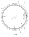
- the cylindrical wall 22 of the stator core 20 extends between a circumferential inner surface 32 and a circumferential outer surface 34, and illustratively includes a plurality of circumferentially-spaced, axially-extending slots 36 ( Fig. 2 ) through which the conductors 30 are received.
- the illustrative stator core 20 of Figs. 1 and 2 includes 60 (sixty) slots 36. Openings to the stator slots 36 are illustratively provided through the inner surface 32 of the stator core 20, as well as the insertion end 14 and the connection end 16 of the stator core 20.
- the slots 36 each support at least a portion of the conductors 30, arranged in armature winding sets, including first (or inner) and second (or outer) winding sets 38 and 40, respectively. More particularly, each slot 36 illustratively includes a portion of both winding sets, including first winding set 38 and second winding set 40. The first winding set 38 in each slot 36 includes two conductors 30 of one phase, and the second winding set 40 in each slot 36 includes two conductors 30 of another phase. Similarly, each of the other slots 36 in the illustrative embodiment also comprise two conductors 30 of one phase and two conductors 30 of another phase.
- each of the slots 36 contain all four conductors 30 of the same phase.
- the illustrative winding arrangement discloses herein is a three-phase winding arrangement, including phases A, B, and C. However, it should be appreciated that the present disclosure may be applied to other multi-phase winding arrangements.
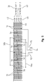
- the conductors 30 are illustratively formed of an electrically conductive material, such as copper, having a rectangular cross-section, and are used to form the armature winding sets 38 and 40. With reference to Figs. 2 and 5 , the conductors 30 are illustratively arranged in four concentric rings or layers, with a first layer 42 positioned closest to the inner surface 32 of the stator core 20, followed by a second layer 44 positioned radially outwardly from the first layer 42, a third layer 46 positioned radially outwardly from the second layer 44, and a fourth layer 48 positioned radially outwardly from the third layer 46 and positioned closest to the outer surface 34 of the stator core 20.
- an electrically conductive material such as copper, having a rectangular cross-section
- the first and second layers 42 and 44 define the first winding set 38, while the third and fourth layers 46 and 48 define the second winding set 40.
- rectangular cross-section conductors 30 may be utilized in order to appropriate the advantages of semi-closed or fully-closed armature slots with a high slot fill ratio (SFR), other conductors (e.g., circular cross-section) may be substituted therefor.
- the electrical conductors 30 for use within the stator assembly 10 illustratively include common conductors 52 ( Figs. 8 and 9 ), short conductors 54 ( Figs. 10 and 11 ), crossover conductors 56 ( Fig. 12 ), neutral conductor 58 ( Fig. 13 ), and terminal phase lead conductor 60 ( Figs. 14-16 ).
- Each of the conductors 52, 54, 56, 58, 60 may be of various hairpin arrangements. Additional details regarding illustrative hairpin conductors are provided in U.S. Patent No. 7,622,843 to Cai , which is assigned to Remy International, Inc., the disclosure of which is expressly incorporated by reference herein.
- the stator assembly 10 illustratively includes a commons region 59 and a specials region 61, which are comprised of the conductors 30.
- electrical connections within the specials region 61 determines the type and configuration of the stator assembly 10.
- the specials region 61 may include, for example, short conductors 54, crossover conductors 56, neutral conductors 58, and terminal phase lead conductor 60 for coupling with external electrical components (not shown).
- An illustrative spacer 100 is positioned within the specials region 61 for positioning and electrically insulating various conductors 30.
- common conductors 52 are used in the first and second winding sets 38 and 40. These are the most numerous (i.e., common) conductors 30 used within the stator assembly 10 and have a general U-shaped hairpin arrangement, including first and second legs 62a and 62b separated by a turn portion 64. Each leg 62a and 62b includes an associated leg end 68a and 68b ( Fig. 8 ). The direction of the conductor 52 changes by substantially 180 degrees at the turn portion 64. Each common conductor 52 spans a predetermined member of slots 36 (i.e., pitch) within its respective winding set 38 and 40.
- each common conductor 52 is configured to span 12 slots of its winding set 38, 40.
- short conductors 54 are similar to the common conductors 52, but have a shorter pitch (i.e., span fewer slots 36).
- the short conductors 54 also have a general U-shaped hairpin arrangement, including first and second legs 72a and 72b, with ends 78a and 78b, separated by a turn portion 74.
- Illustratively 6 short conductors 54 are provided per winding set 38, 40.
- crossover conductors 56 are similar to the hairpin arrangement of common conductors 52, but slightly larger in size since they are used to extend between winding sets 38 and 40 (i.e., spanning a greater distance between slots 36), and provide set-to-set connections between windings in each phase.
- the crossover conductors 56 have first and second legs 53a and 53b, with ends 55a and 55b, separated by a turn portion 57.
- neutral conductors 58 each illustratively have a W shape, including a first leg 82, a second leg 84, and a third leg 86 provided in electrical communication with the fourth layer 48 of the winding arrangement.
- Each neutral conductor 58 may be formed of a U-shaped hairpin conductor 88 and a single leg conductor 90.
- the neutral conductors 58 are used as neutral connections for the winding arrangement.
- inner and outer neutral conductors 58a and 58b are required for the illustrative parallel winding arrangement ( Fig. 5 ).
- terminal phase lead conductor 60 provides terminal ends for each winding phase (A, B, C) on the insertion side of the stator assembly 10 in the illustrative winding arrangement.
- the terminal phase lead conductor 60 comprise three conductors 92, 94, 96, one for each winding phase.
- Each conductor 92, 94, 96 includes an inner leg 92a, 94a, 96a, and an outer leg 92b, 94b, 96b, respectively.
- Connector eyelets 98 are positioned at the end of each terminal phase lead conductor leg 92, 94, 96.
- Fig. 5 further details illustrative special connections including (1) connections required to connect winding sets 38 and 40 (i.e., connections between the second layer 44 and the third layer 46); (2) neutral connections between different phase windings; and (3) terminal connections for each phase winding.
- connections required to connect winding sets 38 and 40 i.e., connections between the second layer 44 and the third layer 46
- neutral connections between different phase windings i.e., connections between the second layer 44 and the third layer 46
- terminal connections for each phase winding may be accomplished by one of the conductors detailed above, for example: (1) crossover conductors 56; (2) neutral conductors 58; and (3) terminal phase lead conductor 60; respectively.
- the first type of special connection is a connection required to connect the two winding sets 38 and 40 (i.e., a connection between the second layer and the first layer). These special connections are illustratively made by the crossover conductors 56.
- the second type of special connection is the neutral connection between different phase windings. This special connection is illustratively made by the neutral conductors 58. The neutral connection may be provided such that the linings are connected in either star-connection or delta-connection for multi-phase machines.
- the third type of special connection is the terminal connection for each phase winding. This special connection is made with the terminal phase lead conductor 60.
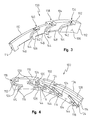
- illustrative spacer 100 for supporting various conductors 52, 54, 56, 58, 60 includes an electrically insulating body 102.
- the body 102 is formed of an electrically non-conductive material, such as a polymer.
- the polymer may be a polytetrafluoroethylene, commonly known as Teflon ® .
- Teflon ® a polytetrafluoroethylene
- the spacer 100 is positioned axially outwardly from the stator core 24 proximate the insertion side 26 thereof.
- the spacer 100 is circumferentially spaced within the specials region 61 of the stator assembly 10, and is configured to locate and isolate various conductors 30 from each other to prevent inadvertent electrical contact and shorting therebetween.
- the spacer 100 may also be used as a pusher or assembly tool to facilitate the insertion of certain conductors 30 within the stator core 24. While the illustrative body 102 is integrally formed during a molding process, in other embodiments the body 102 may be defined by multiple components that interlock to capture various conductors 30.
- the spacer 100 includes a plurality of positioning elements cooperating with various electrical conductors 30 in the specials region of the stator assembly 10, including common conductors 52, short conductors 54, crossover conductors 56, neutral conductor 58, and terminal phase lead conductor 60.
- the body 102 of spacer 100 includes an axially inwardly facing or inner surface 104, and an opposing axially outwardly facing or outer surface 106.
- Arcuate inner and outer sides 108 and 110 extend between opposing ends 112 and 114 of the body 102.
- the inner side 108 faces radially inwardly (toward the center axis 23 of the stator core 20), while the outer side 110 faces radially outwardly (away from the center axis 23 of the stator core 20).
- the spacer 100 includes a first positioning element defined by a first surface 115 supported by the insulating body 102 and which faces axially inwardly for contacting selective short electrical conductors 54 of the inner winding set 38.
- the first surface 115 is collectively defined by a plurality of circumferentially spaced first pegs or pads 116 extending axially inwardly from the inner surface 104 of the spacer 100. Each pad 116 contacts the turn portion 74 of a respective short conductor 54 of the inner winding set 38
- a second positioning element is defined by a second surface 118 supported by the insulating body 102.
- the second surface 118 is positioned radially inwardly from the first surface 114 and faces axially inwardly for contacting a plurality of short electrical conductors 54 of the outer winding set 40.
- the second surface 118 is collectively defined by a plurality of circumferentially spaced second pegs or pads 120 extending axially inwardly from the inner surface 104, the first pads 116 positioned radially inwardly from the second pads 120.
- Each second pad 120 contacts a turn portion 74 of a respective short conductor 54 of the outer winding set 40.
- the inner surface 104 defines a third positioning element or surface supported by the insulating body 102.
- the inner surface 104 faces axially inwardly for contacting a plurality of common conductors 52 within the specials region 61 of the outer winding set 38 and the inner winding set 40. More particularly, the surface 104 contacts turn portions 64 of selective common conductors 52 of the inner and outer winding sets 38 and 40.
- a fourth positioning element is defined by a plurality of crossover pockets 124 extending inwardly within the inner surface 104 of the spacer 100 and extend radially intermediate the first surface 116 and the second surface 120.
- the crossover pockets 124 face axially inwardly for receiving the crossover conductors 56. More particularly, the crossover pockets 124 extend circumferentially and radially intermediate opposing surfaces 108 and 110 for accommodating the turn portions 57 of the crossover conductors 56.
- the crossover pockets 124 are illustratively positioned radially intermediate the first and second pads 116 and 120.
- a fifth positioning element of the spacer 100 is defined by a neutral pocket 128 formed within the spacer 100 for receiving the neutral conductor 58b.
- the neutral pocket 128 is formed within an axially inwardly facing, radially inner edge of the insulating body 102 defined by inner surface 104 and outer side 110.
- a single neutral pocket 128 is shown within insulating body 102 for receiving neutral conductor 58b.
- a second neutral pocket (not shown) may be formed within inner side 108 of the insulating body 102 for receiving the outer neutral conductor 58a.
- At least a portion of the neutral conductor 58 is covered with a melt-processible fluoropolymer, illustratively a fluorinated ethylene propylene (FEP) heat shrink wrap 130, over a sleeve 132 formed of para-aramid synthetic fibers (commonly known as Kevlar ® ) to protect the conductor 58 from abrasion and to provide electrical insulation.
- a melt-processible fluoropolymer illustratively a fluorinated ethylene propylene (FEP) heat shrink wrap 130
- FEP fluorinated ethylene propylene
- a sixth positioning element of the spacer 100 may include a plurality of phase lead pockets 136, 138, 140 supported by the insulating body 102 for receiving the conductors 92, 94, 96 of the phase lead conductor 60.
- the phase lead pockets 136, 138, 140 each include first, second, third, and fourth portions 142, 144, 146, and 148
- the first portion 142 is formed within the outer surface 106 of the body 102 and faces axially outwardly.
- the second portion 144 is an axially extending slot formed within the inner side 108 and facing radially inwardly.
- the third portion 146 is an axially extending slot formed within the outer side 110 and facing radially outwardly.
- the fourth portion 148 is a circumferentially extending slot formed in the inner side 108 of the body 102.
- the first portion 142, the second portion 144, and the fourth portion 148 receive the inner legs 92a, 94a, 96a of the terminal phase lead conductor 60.
- the first portion 142 and the third portion 146 receive the outer legs 92b, 94b, 96b of the terminal phase lead conductor 60.
- the phase lead pockets 136, 138, 140 assist with positioning of eyelets 98 into proper alignment with an external terminal block (not shown). Further, the spacer 100 limits movement of phase lead legs 92, 94, 96 when coupling to the terminal block.
- the body 102 of spacer 100 may be formed with heat dissipating elements.
- channels may be formed within the body 102 and supplied with a fluid (e.g., air or oil) to help dissipate heat from conductors 30 proximate the spacer 100.
- Fig. 17 shows an illustrative embodiment series stator assembly 210.
- Stator assembly 210 is similar to stator assembly 10 but includes conductors 30 interconnected in series as opposed to in parallel. As such, like numbers will identify similar components to those detailed above.
- the series stator assembly 210 includes jumper conductors 211 ( Figs. 20 and 28 ).
- the jumper conductors 211 may have the same hairpin type arrangement as detailed above and are used to connect each of the phase windings in series.
- each jumper conductor 211 includes a pair of legs 213a and 213 b connected by a turn portion 215.
- Fig. 20 is a winding diagram showing illustrative special connections in the parallel stator assembly 210.
- the various conductors in the specials region provide: (1) the connections required to connect winding sets 38 and 40 (i.e., the connection between the second layer 44 and the third layer 46); (2) the neutral connection between different phase windings; (3) the terminal connections for each phase winding; and (4) the connections required to connect each of the phase windings in series (i.e., connections between phase paths).
- Each of these connections may be accomplished by one of the conductors detailed above, for example: (1) crossover conductors 56; (2) neutral conductor 58; (3) terminal phase lead conductor 60; and (4) jumper conductors 211; respectively.
- the first type of special connection is a connection required to connect the two winding sets 38 and 40 (i.e., a connection between the second layer and the first layer). These special connections are illustratively made by the crossover conductors 56.
- the second type of special connection is the neutral connection between different phase windings. This special connection is illustratively made by the neutral conductors 58. The neutral connection may be provided such that the windings are connected in either star-connection or delta-connection for multi-phase machines.
- the third type of special connection is the terminal connection for each phase winding. This special connection is made with the terminal phase lead conductors 60.
- the fourth type of special connection is a connection required to connect same phase winding paths in series. The special connections are made with the jumper conductor 211.
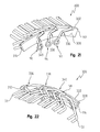
- the spacer 300 includes a body 302 formed of an electrically non-conductive material, such as a polymer.
- the polymer may be a polytetrafluoroethylene, commonly known as Teflon ® .
- Teflon ® a polytetrafluoroethylene
- the spacer 300 is positioned axially outwardly from the stator core 24 proximate the insertion side 14 thereof.
- the spacer 300 is circumferentially spaced within the specials region 61 of the stator assembly 210, and is configured to locate and isolate various conductors 30 from each other to prevent inadvertent electrical contact and shorting therebetween.
- the spacer 300 may also be used as a pusher or assembly tool to facilitate the insertion of certain conductors 30 within the stator core 20.
- the spacer 300 includes a plurality of positioning elements cooperating with various conductors 30 in the specials region 61 of the stator assembly 10, including common conductors 52, short conductors 54, crossover conductors 56, neutral conductor 58, terminal phase lead conductor 60, and jumper conductors 211.
- the body 302 of spacer 300 includes an axially inwardly facing or inner surface 304, and an opposing axially outwardly facing or outer surface 306.
- Arcuate inner and outer sides 308 and 310 extend between opposing ends 312 and 314 of the body 302.
- the inner side 308 faces radially inwardly (toward the center axis 23 of the stator core 20), while the outer side 310 faces radially outwardly (away from the center axis 23 of the stator core 20).
- the spacer 300 includes a positioning element defined by a first surface 315 supported by the insulating body 302 which faces axially inwardly for contacting selective short conductors 54 of the inner winding set 38.
- the first surface 315 is collectively defined by a plurality of circumferentially spaced first pegs or pads 316 extending axially inwardly from the inner surface 304 of the spacer 300.
- a second positioning element is defined by a second surface 318 supported by the insulating body 102. The second surface 318 is positioned radially inwardly from the first surface 314 and faces axially inwardly for contacting a plurality of short conductors 54 of the outer winding set 40.
- the second surface 318 is collectively defined by a plurality of circumferentially spaced second pegs or pads 320 extending axially inwardly from the inner surface 304, the first pads 316 positioned radially inwardly from the second pads 320.
- the inner surface 304 defines a third positioning element of surface supported by the insulating body 302.
- the inner surface 304 faces axially inwardly for contacting a plurality of common conductors 52 within the specials region 61 of the outer winding set 38 and the inner winding set 40.
- a fourth positioning element is defined by a plurality of crossover pockets 324 extending inwardly within the inner surface 304 of the spacer 300 and extending radially intermediate the first surface 316 and the second surface 320.
- the crossover pockets 324 face axially inwardly for receiving the crossover conductors 56. More particularly, the crossover pockets 324 extend circumferentially and radially intermediate opposing surfaces 308 and 310 for accommodating the turn portions 57 of the crossover conductors 56.
- the crossover pockets 324 are illustratively positioned radially intermediate the first and second pads 316 and 320.
- a fifth positioning element of the spacer 300 is a neutral pocket 328 formed within the spacer 300 for receiving the neutral conductor 58.
- the neutral pocket 328 is formed within an axially inwardly facing, radially inner edge of the insulating body 302 defined by inner surface 304 and outer side 310.
- a sixth positioning element of the spacer 300 includes a plurality of phase lead pockets 336, 338, 340 supported by the insulating body 302.
- the phase lead pockets 336, 338, 340 each include a first portion 342, and a second portion 344.
- the first portion 342 is formed within the outside surface 306 of the body 302 and faces axially outwardly.
- the second portion 344 is an axially extending slot formed within outer side 310 and facing radially outwardly. The first portion 342 and the second portion 344 receive the legs 92, 94, 96 of the terminal phase lead conductors 60.
- the jumper conductor 211 is received within a jumper pocket 350 formed within an axially inwardly facing, radially inner edge of the insulating body 302 defined by inner surface 304 and inner side 308.
- the jumper pocket 350 extends circumferentially and receives the turn portion 215 of the jumper conductor 211.
- stator assembly 10 An illustrative method forming stator assembly 10 is detailed herein. Except as otherwise noted, the method of forming stator assembly 210 will be substantially the same.
- the illustrative method includes the steps of providing the stator core 20 and inserting a plurality of common conductors 52 and short conductors 54 within the core 20. More particularly, the common conductors 52 and the short conductors 54 are inserted into selective slots 36 through the insertion end 14 of the stator core 20. A plurality of crossover conductors 56 are also inserted within selective slots 36 at the insertion end 14 of the stator core 20. Neutral conductors 58 are also received within the insertion end 14 of selective slots 36 in the stator core 20. In the series stator assembly 210, jumper conductors 211 are inserted into the stator core 20 and replace one of the neutral conductors 58.
- the spacer 100 is positioned proximate the insertion end 14 of the stator core 20, wherein the first and second surfaces 115 and 118 of the spacer 100 are aligned with the short conductors 54, the crossover pockets 124 are aligned with the crossover conductors 56, and the inner surface 104 is aligned with the common conductors 52.
- Spacer 100 is then moved toward the insertion end 14 of the stator core 20 such that the short conductors 54 engage the first and second surfaces 115 and 118 and are pushed into the respective slots 36 in the stator core 20, and the crossover conductors 56 are received within the crossover pockets 124 of the spacer 100.
- the inner surface 104 of the spacer 100 may rest against the turn portions 64 of the common conductors 52.
- the neutral conductor 58 is also positioned within the neutral pocket 128 of the spacer 100.
- a selective jump conductor 211 is positioned within the jump pocket 350 of the spacer 300.
- the terminal phase leads conductor 60 may be positioned within the phase lead pockets 136, 138, 140 of the spacer 100.
- the spacers 100 and 300 detailed herein provide fixed spacing between various conductors 30 within the specials region 61 of the respective stator assembly 10 and 210. Spacer 100, 300 also assists with fixed positioning of phase lead eyelets 98 for proper alignment with a terminal block. Body 102, 302 of each spacer 100, 300 provides for electrical insulation between the respective conductors 30 within the specials region 61. Given the spatial orientation and electrical insulation functions of the spacer 100, 300, insulation material typically applied to individual conductors 30 may be eliminated in many instances. Additionally, the spacers 100 and 300 may be used as an assembly tool permitting simultaneous insertion of conductors 30 within the specials region 61 while maintaining relative spacing between the inserted conductors 30.
Landscapes
- Engineering & Computer Science (AREA)
- Power Engineering (AREA)
- Insulation, Fastening Of Motor, Generator Windings (AREA)
Applications Claiming Priority (1)
| Application Number | Priority Date | Filing Date | Title |
|---|---|---|---|
| US13/314,031 US8749107B2 (en) | 2011-12-07 | 2011-12-07 | Spacer for supporting conductors in an electric machine |
Publications (2)
| Publication Number | Publication Date |
|---|---|
| EP2602914A2 true EP2602914A2 (de) | 2013-06-12 |
| EP2602914A3 EP2602914A3 (de) | 2014-12-03 |
Family
ID=47665800
Family Applications (1)
| Application Number | Title | Priority Date | Filing Date |
|---|---|---|---|
| EP12195353.3A Withdrawn EP2602914A3 (de) | 2011-12-07 | 2012-12-03 | Leiterabstandshalter einer elektrischen Maschine |
Country Status (5)
| Country | Link |
|---|---|
| US (1) | US8749107B2 (de) |
| EP (1) | EP2602914A3 (de) |
| JP (1) | JP2013121317A (de) |
| KR (1) | KR20130064033A (de) |
| CN (1) | CN103151867A (de) |
Cited By (2)
| Publication number | Priority date | Publication date | Assignee | Title |
|---|---|---|---|---|
| WO2021074564A1 (en) * | 2019-10-18 | 2021-04-22 | Dyson Technology Limited | A stator assembly for an electric motor |
| EP3637599B1 (de) * | 2018-10-09 | 2022-08-17 | Delta Electronics, Inc. | Motorstator und formungsverfahren dafür |
Families Citing this family (23)
| Publication number | Priority date | Publication date | Assignee | Title |
|---|---|---|---|---|
| US8878406B2 (en) * | 2011-12-06 | 2014-11-04 | Remy Technologies, L.L.C. | Stator including conductors provided with a composite sleeve |
| DE102013111868A1 (de) * | 2013-10-28 | 2015-04-30 | Ebm-Papst St. Georgen Gmbh & Co. Kg | Stator für einen Elektromotor |
| CN103795170B (zh) * | 2014-01-07 | 2016-02-03 | 锦州汉拿电机有限公司 | 车辆用发电机或驱动马达的定子总成 |
| JP5902726B2 (ja) * | 2014-01-15 | 2016-04-13 | トヨタ自動車株式会社 | 回転電機ステータ |
| CN104052173A (zh) * | 2014-07-01 | 2014-09-17 | 柏科(常熟)电机有限公司 | 一种用于汽车发电机的定子 |
| CN106605355B (zh) * | 2014-09-29 | 2019-03-08 | 日立汽车系统株式会社 | 旋转电机的定子以及具备该旋转电机的定子的旋转电机 |
| JP6235504B2 (ja) * | 2015-02-17 | 2017-11-22 | ファナック株式会社 | 分布巻のラジアルギャップ型モータおよびその巻線配置方法 |
| CN109075647B (zh) * | 2016-05-11 | 2020-11-03 | 日立汽车系统株式会社 | 旋转电机 |
| JP6799962B2 (ja) * | 2016-08-03 | 2020-12-16 | 本田技研工業株式会社 | バスバーユニット |
| DE102017208706A1 (de) * | 2016-09-27 | 2018-03-29 | Robert Bosch Gmbh | Stator für eine elektrische Maschine |
| DE102016220119A1 (de) * | 2016-10-14 | 2018-04-19 | Robert Bosch Gmbh | Elektromotor mit einer Leiterführung |
| CN110546861B (zh) * | 2017-04-19 | 2021-10-26 | Lg麦格纳电子动力总成有限公司 | 旋转电子设备的定子 |
| CN114268266A (zh) * | 2017-06-23 | 2022-04-01 | 台达电子工业股份有限公司 | 马达控制系统 |
| EP3641111A1 (de) * | 2018-10-19 | 2020-04-22 | ATOP S.p.A. | Verfahren und vorrichtung zur herstellung eines stators |
| DE102019202911A1 (de) * | 2019-03-05 | 2020-09-10 | Zf Friedrichshafen Ag | Verschaltungsanordnung und Stator für eine elektrische Maschine |
| DE102019105563A1 (de) * | 2019-03-05 | 2020-09-10 | Valeo Siemens Eautomotive Germany Gmbh | Stator mit Pins und einer Schnittstelle für eine elektrische Maschine |
| CN110445280B (zh) * | 2019-08-14 | 2024-08-02 | 苏州汇川联合动力系统股份有限公司 | 定子端部连接组件及扁线电机 |
| US11936264B2 (en) * | 2019-12-19 | 2024-03-19 | Borgwarner Inc. | Busbar for electric machine |
| KR102655283B1 (ko) | 2020-04-20 | 2024-04-08 | 엘지마그나 이파워트레인 주식회사 | 전동기의 스테이터 |
| DE102021203210A1 (de) | 2021-03-30 | 2022-10-06 | Valeo Siemens Eautomotive Germany Gmbh | Isolationsvorrichtung, Stator und elektrische Maschine |
| EP4300784A1 (de) | 2022-06-28 | 2024-01-03 | Valeo eAutomotive Germany GmbH | Statorvorrichtung für eine elektrische maschine und elektrischer antrieb für ein fahrzeug |
| EP4300780A1 (de) | 2022-06-28 | 2024-01-03 | Valeo eAutomotive Germany GmbH | Anschlussvorrichtungen für einen stator einer elektrischen maschine, statorvorrichtung für eine elektrische maschine und elektrischer antrieb für ein fahrzeug |
| DE102023203102A1 (de) * | 2023-04-04 | 2024-10-10 | Zf Friedrichshafen Ag | Anschraubschnittstelle für eine elektrische Maschine mit Hairpin-Wicklung |
Citations (1)
| Publication number | Priority date | Publication date | Assignee | Title |
|---|---|---|---|---|
| US7622843B2 (en) | 2006-06-12 | 2009-11-24 | Rerry International, Inc. | Terminals and connections between multi-set segmented hairpin windings |
Family Cites Families (29)
| Publication number | Priority date | Publication date | Assignee | Title |
|---|---|---|---|---|
| JP2618296B2 (ja) | 1991-07-16 | 1997-06-11 | 日本原子力研究所 | 電磁気固定子 |
| JP2636144B2 (ja) * | 1993-09-06 | 1997-07-30 | 日本サーボ株式会社 | 電動機ステータコイルの締結具と締結装置および締結方法 |
| DE19544830A1 (de) | 1995-12-01 | 1997-06-05 | Mulfingen Elektrobau Ebm | Stator für Elektromotoren |
| JP3627082B2 (ja) * | 1996-06-25 | 2005-03-09 | 三菱電機株式会社 | 電動機およびその製造方法 |
| DE19920127C2 (de) | 1999-05-03 | 2001-05-31 | Mannesmann Sachs Ag | Stator für eine elektrische Maschine und Verfahren zur Herstellung eines Stators |
| US6232681B1 (en) | 2000-03-23 | 2001-05-15 | Delco Remy International, Inc. | Electromagnetic device with embedded windings and method for its manufacture |
| JP3672846B2 (ja) | 2001-05-29 | 2005-07-20 | 三菱電機株式会社 | 車両用交流発電機 |
| US6545243B1 (en) | 2001-09-14 | 2003-04-08 | Delco Remy America, Inc. | Dynamic weld power termination for hot-staking armature commutators |
| JP3740421B2 (ja) | 2002-01-10 | 2006-02-01 | 株式会社日立製作所 | 回転電機と固定子導線の接続方法 |
| US20030214190A1 (en) | 2002-05-15 | 2003-11-20 | Delco Remy America | Connection device for hairpin wound electric machines |
| DE10321956B4 (de) | 2002-05-15 | 2013-09-12 | Remy Inc. | Wicklungen aus rechtwinkligen Kupferhaarnadeln in mehreren Sätzen für elektrische Maschinen |
| US6825586B2 (en) | 2002-10-29 | 2004-11-30 | Remy, Inc. | One piece stator lead and terminal insulator |
| US7256364B2 (en) | 2004-12-21 | 2007-08-14 | Remy International, Inc. | Method for simultaneous resistance brazing of adjacent conductor joints |
| US7348705B2 (en) | 2005-07-21 | 2008-03-25 | Remy Technologies, L.L.C. | Multi-phase fractional slot windings for electric machines having segmented bar-shaped windings |
| JP4137101B2 (ja) * | 2005-08-17 | 2008-08-20 | 山洋電気株式会社 | 回転電機 |
| JP4980631B2 (ja) * | 2006-03-16 | 2012-07-18 | トヨタ自動車株式会社 | 相間絶縁部材および回転電機 |
| US7788790B2 (en) | 2006-03-27 | 2010-09-07 | Remy Technologies, L.L.C. | Method for forming a stator core |
| US7687954B2 (en) | 2006-03-30 | 2010-03-30 | Remy Technologies, L.L.C. | Brushless electric machine with stator with cascaded end loops |
| US7808137B2 (en) | 2006-10-05 | 2010-10-05 | Remy Technologies, L.L.C. | Single track layer stator terminal assembly |
| JP2008125307A (ja) * | 2006-11-15 | 2008-05-29 | Mitsuba Corp | ブラシレスモータ用ステータ及びブラシレスモータ |
| JP4946421B2 (ja) | 2006-12-20 | 2012-06-06 | 株式会社デンソー | 回転電機の巻線接合方法 |
| US7808148B2 (en) | 2007-09-11 | 2010-10-05 | Remy International | Stator winding assembly and method |
| US7911105B2 (en) | 2008-01-10 | 2011-03-22 | Remy International, Inc. | Stator winding having same radial positions |
| JP5417081B2 (ja) * | 2009-08-05 | 2014-02-12 | 日立オートモティブシステムズ株式会社 | 回転電機 |
| JP2011045202A (ja) * | 2009-08-21 | 2011-03-03 | Aisin Aw Co Ltd | 回転電機用電機子及び絶縁部材 |
| KR101070997B1 (ko) * | 2009-11-03 | 2011-10-06 | 뉴모텍(주) | 압축기용 모터의 스테이터 |
| JP5586969B2 (ja) | 2010-01-21 | 2014-09-10 | 株式会社デンソー | 回転電機の固定子 |
| JP5768323B2 (ja) * | 2010-03-26 | 2015-08-26 | アイシン精機株式会社 | 回転電機のステータ |
| JP5004110B2 (ja) * | 2010-07-30 | 2012-08-22 | 本田技研工業株式会社 | アウターロータ型突極集中巻き電動機 |
-
2011
- 2011-12-07 US US13/314,031 patent/US8749107B2/en active Active
-
2012
- 2012-12-03 EP EP12195353.3A patent/EP2602914A3/de not_active Withdrawn
- 2012-12-07 JP JP2012283512A patent/JP2013121317A/ja active Pending
- 2012-12-07 KR KR1020120141714A patent/KR20130064033A/ko not_active Withdrawn
- 2012-12-07 CN CN2012105247092A patent/CN103151867A/zh active Pending
Patent Citations (1)
| Publication number | Priority date | Publication date | Assignee | Title |
|---|---|---|---|---|
| US7622843B2 (en) | 2006-06-12 | 2009-11-24 | Rerry International, Inc. | Terminals and connections between multi-set segmented hairpin windings |
Cited By (3)
| Publication number | Priority date | Publication date | Assignee | Title |
|---|---|---|---|---|
| EP3637599B1 (de) * | 2018-10-09 | 2022-08-17 | Delta Electronics, Inc. | Motorstator und formungsverfahren dafür |
| WO2021074564A1 (en) * | 2019-10-18 | 2021-04-22 | Dyson Technology Limited | A stator assembly for an electric motor |
| GB2588224B (en) * | 2019-10-18 | 2023-04-19 | Dyson Technology Ltd | A stator assembly for an electric motor |
Also Published As
| Publication number | Publication date |
|---|---|
| US8749107B2 (en) | 2014-06-10 |
| JP2013121317A (ja) | 2013-06-17 |
| CN103151867A (zh) | 2013-06-12 |
| US20130147306A1 (en) | 2013-06-13 |
| KR20130064033A (ko) | 2013-06-17 |
| EP2602914A3 (de) | 2014-12-03 |
Similar Documents
| Publication | Publication Date | Title |
|---|---|---|
| US8749107B2 (en) | Spacer for supporting conductors in an electric machine | |
| CN108462277B (zh) | 用于定子组件的分布式连接环组件 | |
| EP2273654B1 (de) | Elektrische Drehmaschine und Herstellungsverfahren dafür | |
| US9748810B2 (en) | Motor and method for manufacturing stator therefor | |
| US8674577B2 (en) | Stator for electric rotating machine | |
| US9362809B2 (en) | Stator for electric rotary machine and fabricating method of the same | |
| US8487498B2 (en) | Multiple conductor winding in stator | |
| US20140015358A1 (en) | Integrated phase connection isolator with individual phase isolator | |
| EP0717488A2 (de) | Nulleiterverbindung für drahtgewickelten Stator | |
| KR102716136B1 (ko) | 폴 체인으로 형성된 스테이터 및 에나멜 알루미늄 와이어의 비접촉식 라우팅을 구비한 전기 모터 | |
| US12046972B2 (en) | Motor and stator bus bar | |
| EP2913907B1 (de) | Stator für rotierende elektrische maschinen | |
| US9641036B2 (en) | Rotary electric machine | |
| KR102761030B1 (ko) | 축 방향 자속 전기 기계 | |
| US8203251B2 (en) | Stator with restraints for restraining relative radial movement between turn portions of electric wires | |
| US20140125185A1 (en) | Stator and rotating electric machine | |
| WO2012100041A2 (en) | Stator winding connection arrangement | |
| JP2014079090A (ja) | 回転電機のステータ用のバスリング | |
| US8659201B2 (en) | Stator for electric rotating machine | |
| US8907540B2 (en) | Electric machine with insulator spacer | |
| EP2871755B1 (de) | Drehmaschine | |
| EP2095489B1 (de) | Rotorpolquerverbindung einschliesslich querfugen | |
| KR102761028B1 (ko) | 축 방향 자속 전기 기계 | |
| CN115037079B (zh) | 马达 | |
| JP5972154B2 (ja) | 回転電機 |
Legal Events
| Date | Code | Title | Description |
|---|---|---|---|
| PUAI | Public reference made under article 153(3) epc to a published international application that has entered the european phase |
Free format text: ORIGINAL CODE: 0009012 |
|
| AK | Designated contracting states |
Kind code of ref document: A2 Designated state(s): AL AT BE BG CH CY CZ DE DK EE ES FI FR GB GR HR HU IE IS IT LI LT LU LV MC MK MT NL NO PL PT RO RS SE SI SK SM TR |
|
| AX | Request for extension of the european patent |
Extension state: BA ME |
|
| PUAL | Search report despatched |
Free format text: ORIGINAL CODE: 0009013 |
|
| AK | Designated contracting states |
Kind code of ref document: A3 Designated state(s): AL AT BE BG CH CY CZ DE DK EE ES FI FR GB GR HR HU IE IS IT LI LT LU LV MC MK MT NL NO PL PT RO RS SE SI SK SM TR |
|
| AX | Request for extension of the european patent |
Extension state: BA ME |
|
| RIC1 | Information provided on ipc code assigned before grant |
Ipc: H02K 3/50 20060101AFI20141024BHEP |
|
| STAA | Information on the status of an ep patent application or granted ep patent |
Free format text: STATUS: THE APPLICATION IS DEEMED TO BE WITHDRAWN |
|
| 18D | Application deemed to be withdrawn |
Effective date: 20150604 |